EP0201107A2 - Device for curing fingernail substitutes by light - Google Patents
Device for curing fingernail substitutes by lightDownload PDFInfo
- Publication number
- EP0201107A2 EP0201107A2EP86106355AEP86106355AEP0201107A2EP 0201107 A2EP0201107 A2EP 0201107A2EP 86106355 AEP86106355 AEP 86106355AEP 86106355 AEP86106355 AEP 86106355AEP 0201107 A2EP0201107 A2EP 0201107A2
- Authority
- EP
- European Patent Office
- Prior art keywords
- low
- pressure fluorescent
- fluorescent tubes
- pressure
- protective housing
- Prior art date
- Legal status (The legal status is an assumption and is not a legal conclusion. Google has not performed a legal analysis and makes no representation as to the accuracy of the status listed.)
- Granted
Links
Images


Classifications
- A—HUMAN NECESSITIES
- A45—HAND OR TRAVELLING ARTICLES
- A45D—HAIRDRESSING OR SHAVING EQUIPMENT; EQUIPMENT FOR COSMETICS OR COSMETIC TREATMENTS, e.g. FOR MANICURING OR PEDICURING
- A45D29/00—Manicuring or pedicuring implements
- A45D29/18—Manicure or pedicure sets, e.g. combinations without case, etui, or the like
- A—HUMAN NECESSITIES
- A45—HAND OR TRAVELLING ARTICLES
- A45D—HAIRDRESSING OR SHAVING EQUIPMENT; EQUIPMENT FOR COSMETICS OR COSMETIC TREATMENTS, e.g. FOR MANICURING OR PEDICURING
- A45D31/00—Artificial nails
Definitions
- the inventionrelates to a device for curing light-curing fingernail or toenail replacements.
- light-curing substancesin medical technology, for example for the restoration of broken limbs, is known per se. These substances harden under the influence of light, preferably in the U-V range (light, as in the following, should not only be understood to mean visible light but also ultraviolet radiation).
- the inventionhas for its object to provide a device for curing light-curing fingernail or toenail replacement, which is simple in construction and inexpensive to manufacture and with the artificial fingernails or toenails under precise reproducible conditions can be cured in a reliable manner.
- This objectis achieved in a device of the type mentioned at the outset by a support plate and at least one low-pressure fluorescent tube arranged at a distance from the support plate.
- the radiation from a low-pressure fluorescent tubewhich is usually in a spectral range from 320 nm to 520 nm, has proven to be surprisingly advantageous for curing artificial fingernails or toenails and has led to consistent results.
- a support plateis provided for the hand or foot of the patient and thus the distance between the radiation source and the object to be treated is always the same, constant and thus reproducible radiation conditions can be achieved. Overdosing and underdosing of the radiation, which could be caused by too small or too large a distance between the radiation source and the object, are avoided.
- An embodiment of the inventionwhich is particularly advantageous in terms of construction technology is characterized in that the low-pressure fluorescent tube is arranged on a support fastened to the support plate. In this way there is a compact device consisting of a support plate, support and fluorescent tube.
- the power supply and the base for the low-pressure fluorescent tubecan advantageously be arranged in the carrier.
- a plurality of axially parallel, preferably four to six, low-pressure fluorescent tubesare provided. This enables particularly uniform irradiation achieve all fingernails of one hand.
- the low-pressure fluorescent tubesare arranged according to a further advantageous development of the inventive concept so that the intersection of their longitudinal axes with a plane perpendicular to the axes lie on an arc-shaped curve, the nail on the thumb of a hand is usually the one placed on a flat plate Hand is almost perpendicular to this plate, irradiated with the same intensity as the other nails of the hand, since the arrangement of the low-pressure fluorescent tubes in an arc shape results in a kind of radiation tunnel.
- the low-pressure fluorescent tubesare U-shaped and have a base on one side.
- one side of the fluorescent tubescan be kept completely free of brackets and electrical connections.
- the patient's hand or footis expediently placed under the fluorescent tubes from this free side, i. H. brought on the platen. Touching the tube bases is avoided.
- the described embodimentis also advantageous from a constructional point of view because only a single carrier is required for the fluorescent tube or tubes. The manufacturing costs are correspondingly low.
- low-pressure fluorescent tubes with a mercury vapor fillingare provided.
- these tubeswhich emit radiation with a wavelength of 320 nm to 520 nm, preferably with a wavelength of 360 nm to 450 nm, excellent results were achieved in the curing of artificial nail replacement.
- a protective housingis provided with an engagement opening adapted to the shape of a hand or a foot, by means of which the light source is protected from damage and, on the other hand, the surroundings are protected from emerging radiation.
- the protective housingalso covers all electrical parts, such as the power supply for the fluorescent tubes. If the protective housing is tunnel-shaped and, in particular, according to a further advantageous embodiment, the longitudinal axis of the tunnel-shaped protective housing is parallel to the longitudinal axis of the low-pressure fluorescent tubes, the inner wall of the protective housing can be used as a reflector, which increases the uniformity of the illumination of the object within the device and also increases the Effective use of radiation from the fluorescent tubes.
- the reflective effectis further increased by covering the inside of the protective housing with a reflector. This can consist of a film or of plate-shaped reflective material.
- ventilation slotsare provided in the protective housing, so that the air heated by the fluorescent tubes and the voltage supply is effectively drawn off. This avoids heating the interior of the device, which could easily lead to feelings of fear in sensitive patients.
- a measuring devicewhich detects the irradiation time.
- the irradiation timeis, as it were, recorded automatically with the aid of a light barrier arranged on the support plate, which triggers a timer when a hand or foot is inserted into the device for irradiation purposes.
- the timerAfter a certain, preferably adjustable, time has elapsed, the timer generates a control signal which is fed to the input of an acoustic signal transmitter.
- the acoustic signal generatorthus indicates the end of the treatment process after a certain time.
- the signal transmitteris connected to the receiver of the light barrier and receives an enable signal from the latter when the light path in the light barrier is interrupted.
- This release signalensures that an acoustic signal is only emitted by the signal generator when the timer has expired and the object to be treated is still in the device.
- the power supply to the low-pressure fluorescent tubesis interrupted directly by a relay, so that irradiation beyond the prescribed period of time is not possible.
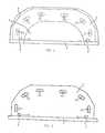
- FIG. 1a device for curing light-curing fingernail or toenail replacement is shown in the front view.
- a support plate 1can be seen, at one end of which a support 3 is attached perpendicular to the base of the support plate 1 (see also FIGS. 2 and 3).
- the carrier 3contains six brackets for U-shaped, low-pressure fluorescent tubes 2a-2f which are capped on one side.
- the fluorescent tubes 2a-2fare arranged on the carrier so that they lie on an arcuate curve thereon. It is a widely spread wide arch that is slightly wider than a human hand or foot.
- the U-shaped fluorescent tubesare fastened in such a way that the surface normal of a surface passing through the two central axes of the tube parts of a fluorescent tube points approximately into the central region of the support plate 1, in order to achieve optimum radiation utilization there.
- the deviceis covered with a protective housing 4, which on the front side has an engagement opening 5 adapted to the shape of a human hand or foot.
- the protective housingis tunnel-shaped and extends in the same direction as the fluorescent tubes arranged on the carrier 3. It is reflective on the inside Foil (not shown) occupied.
- a light barrierconsisting of a transmitter 6 and a receiver 7 is arranged on the plate 1.
- the transmitterusually consists of a light emitting diode and the receiver 7 of a photocell.
- the light barrieris located in the front area of the support plate 1, ie directly in the area of the engagement opening 5 of the protective housing 4.
- Incbm carrier 3(not shown) houses the voltage supply and the electronic parts for the irradiation time measuring device.
- a hand inserted into the deviceis indicated by dashed lines in FIG. 3 for illustration purposes.
- a power supply 10supplies the transmitter 6 of the light barrier and an electronic timer 8.
- the trigger input of the timer 8is connected to the receiver 7 of the light barrier.
- the signal output of the timer 8is connected to a control signal input of an acoustic signal generator 9. Further, the output of the light barrier receiver 7 is connected to an enable signal input of the S ignalgebers. 9
- FIG. 5shows a further embodiment, in which, in deviation from the embodiment according to FIG. 1, only a single, centrally arranged low-pressure fluorescent tube 2 is provided.
- This deviceis particularly inexpensive to manufacture. Surprisingly, it has been found that when using the tunnel-shaped, occupied on its inner side with a reflection film protective housing 4, even with this simplified device at least satisfactory rgeb- E could be obtained in the curing nit.
Landscapes
- Radiation-Therapy Devices (AREA)
Abstract
Description
Translated fromGermanDie Erfindung bezieht sich auf eine Vorrichtung zum Aushärten von lichthärtendem Fingernagel- oder Fußnagelersatz.The invention relates to a device for curing light-curing fingernail or toenail replacements.
Künstliche Finger- oder Fußnägel, die zur Ergänzung teilweise beschädigter Nägel oder beispielsweise als Nagelersatz so lange dienen, bis ein natürlicher Nagel nach einem Unfall nachgewachsen ist, wurden bislang aus che-' misch härtenden Substanzen hergestellt.Artificial fingernails or toenails, the supplementing partially damaged nails or nail, for example, serve as a substitute so long as it is grown to a natural nail after an accident, have so far been made of chemical'mixed curing agents.
Die Verwendung von lichthärtenden Substanzen in der medizinischen Technik, beispielsweise zum Stillegen gebrochener Gliedmaßen ist an sich bekannt. Diese Substanzen härten unter Lichteinstrahlung, vorzugsweise im U-V-Bereich aus (unter Licht soll hier wie im Folgenden nicht nur sichtbares Licht, sondern auch ultraviolette Strahlung verstanden werden).The use of light-curing substances in medical technology, for example for the restoration of broken limbs, is known per se. These substances harden under the influence of light, preferably in the U-V range (light, as in the following, should not only be understood to mean visible light but also ultraviolet radiation).
Der Erfindung liegt die Aufgabe zugrunde, eine Vorrichtung zum Aushärten von lichthärtendem Fingernagel- oder Fußnagelersatz zu schaffen, die einfach aufgebaut und kostengünstig herzustellen ist und mit der künstliche Fingernägel oder Fußnägel unter präzise reproduzierbaren Bedingungen in zuverlässiger Weise ausgehärtet werden können.The invention has for its object to provide a device for curing light-curing fingernail or toenail replacement, which is simple in construction and inexpensive to manufacture and with the artificial fingernails or toenails under precise reproducible conditions can be cured in a reliable manner.
Diese Aufgabe ist bei einer Vorrichtung der eingangs genannten Art, durch eine Auflageplatte und mindestens eine im Abstand zu der Auflageplatte angeordnete Niederdruckleuchtstoffröhre.gelöst.This object is achieved in a device of the type mentioned at the outset by a support plate and at least one low-pressure fluorescent tube arranged at a distance from the support plate.
Die Strahlung einer Niederdruckleuchtstoffröhre, die üblicherweise in einem Spektralbereich von 320 nm bis 520 nm liegt, hat sich zur Aushärtung von künstlichen Finger-oder Fußnägeln als überraschend vorteilhaft erwiesen und zu gleichbleibenden Ergebnissen geführt. Dadurch, daß weiterhin erfindungsgemäß eine Auflageplatte für die Hand oder den Fuß des Patienten vorgesehen ist und somit der Abstand zwischen der Strahlungsquelle und dem zu behandelnden Objekt stets der gleiche ist, lassen sich konstante und somit reproduzierbare Bestrahlungsverhältnisse erzielen. über- und Unterdosierungen der Strahlung, die durch zu geringen oder zu großen Abstand zwischen Strahlungsquelle und Objekt hervorgerufen werden könnten, werden vermieden.The radiation from a low-pressure fluorescent tube, which is usually in a spectral range from 320 nm to 520 nm, has proven to be surprisingly advantageous for curing artificial fingernails or toenails and has led to consistent results. The fact that, according to the invention, a support plate is provided for the hand or foot of the patient and thus the distance between the radiation source and the object to be treated is always the same, constant and thus reproducible radiation conditions can be achieved. Overdosing and underdosing of the radiation, which could be caused by too small or too large a distance between the radiation source and the object, are avoided.
Eine in konstruktionstechnischer Sicht besonders vorteilhafte Ausführungsform der Erfindung zeichnet sich dadurch aus, daß die Niederdruckleuchtstoffröhre an einem an der Auflageplatte befestigten Träger angeordnet ist. Auf diese Weise gibt sich ein kompaktes Gerät, bestehend aus Auflageplatte, Träger und Leuchtstoffröhre. Dabei kann vorteilhafterweise die Stromversorgung sowie der Sockel für die Niederdruckleuchtstoffröhre in dem Träger angeordnet sein.An embodiment of the invention which is particularly advantageous in terms of construction technology is characterized in that the low-pressure fluorescent tube is arranged on a support fastened to the support plate. In this way there is a compact device consisting of a support plate, support and fluorescent tube. The power supply and the base for the low-pressure fluorescent tube can advantageously be arranged in the carrier.
Nach einer besonders vorteilhaften Ausführungsform der Erfindung sind mehrere achsparallele, vorzugsweise vier bis sechs Niederdruckleuchtstoffröhren vorgesehen. Hierdurch läßt sich eine besonders gleichmäßige Bestrahlung sämtlicher Fingernägel einer Hand erzielen. Wenn dabei die Niederdruckleuchtstoffröhren nach einer weiteren vorteilhaften Weiterbildung des Erfindungsgedankens so angeordnet sind, daß die Schnittpunkte ihrer Längsachsen mit einer zu den Achsen senkrechten Ebenen auf einer bogenförmigen Kurve liegen, wird auch der Nagel am Daumen einer Hand der üblicherweise bei einer auf eine flache Platte gelegten Hand nahezu senkrecht zu dieser Platte steht, mit gleicher Intensität wie die anderen Nägel der Hand bestrahlt, da sich durch die Anordnung der Niederdruckleuchtstoffröhren in Bogenform gewissermaßen ein Bestrahlungstunnel ergibt.According to a particularly advantageous embodiment of the invention, a plurality of axially parallel, preferably four to six, low-pressure fluorescent tubes are provided. This enables particularly uniform irradiation achieve all fingernails of one hand. If the low-pressure fluorescent tubes are arranged according to a further advantageous development of the inventive concept so that the intersection of their longitudinal axes with a plane perpendicular to the axes lie on an arc-shaped curve, the nail on the thumb of a hand is usually the one placed on a flat plate Hand is almost perpendicular to this plate, irradiated with the same intensity as the other nails of the hand, since the arrangement of the low-pressure fluorescent tubes in an arc shape results in a kind of radiation tunnel.
Unter sicherheitstechnischen überlegungen hat sich eine Ausführungsform als besonders vorteilhaft erwiesen, bei der die Niederdruckleuchtstoffröhren U-förmig ausgebildet und einseitig gesockelt sind. Bei dieser Bauweise kann eine Seite der Leuchtstoffröhren völlig frei von Halterungen und elektrischen Anschlüssen gehalten werden. Zweckmäßigerweise wird die Hand oder der Fuß des Patienten von dieser freien Seite unter die Leuchtstoffröhren, d. h. auf die Auflageplatte gebracht. Eine Berührung mit den Röhrensockeln ist dabei vermieden. Ferner ist die beschriebene Ausführungsform auch unter konstruktionstechnischen Gesichtspunkten vorteilhaft, weil für die Leuchtstoffröhre bzw. die Leuchtstoffröhren nur ein einziger Träger benötigt wird. Entsprechend niedrig sind die Herstellungskosten.Under safety-related considerations, an embodiment in which the low-pressure fluorescent tubes are U-shaped and have a base on one side has proven particularly advantageous. With this design, one side of the fluorescent tubes can be kept completely free of brackets and electrical connections. The patient's hand or foot is expediently placed under the fluorescent tubes from this free side, i. H. brought on the platen. Touching the tube bases is avoided. Furthermore, the described embodiment is also advantageous from a constructional point of view because only a single carrier is required for the fluorescent tube or tubes. The manufacturing costs are correspondingly low.
Nach einer weiteren Ausführungsform sind Niederdruckleuchtstoffröhren mit einer Quecksilberdampffüllung vorgesehen. Mit diesen Röhren, die Strahlung mit einer Wellenlänge von 320 nm bis 520 nm vorzugsweise mit einer Wellenlänge von 360 nm bis 450 nm emitieren, konnten hervorragende Ergebnisse bei der Aushärtung von künstlichem Nagelersatz erzielt werden.According to a further embodiment, low-pressure fluorescent tubes with a mercury vapor filling are provided. With these tubes, which emit radiation with a wavelength of 320 nm to 520 nm, preferably with a wavelength of 360 nm to 450 nm, excellent results were achieved in the curing of artificial nail replacement.
Nach einer weiteren vorteilhaften Ausführungsform ist ein Schutzgehäuse mit einer an die Form einer Hand oder eines Fußes angepaßten Eingriffsöffnung vorgesehen, durch das die Lichtquelle vor Beschädigung und andererseits die Umgebung vor austretender Strahlung geschützt wird. Ferner deckt das Schutzgehäuse auch alle elektrischen Teile, wie beispielsweise die Spannungsversorgung für die Leuchtstoffröhren ab. Wenn das Schutzgehäuse tunnelförmig ausgebildet ist und insbesondere nach einer weiteren vorteilhaften Ausführungsform die Längsachse des tunnelförmigen Schutzgehäuses parallel zur Längsachse der Niederdruckleuchtstoffröhren ist, kann die Innenwand des Schutzgehäuses als Reflektor verwendet werden, rer die Gleichmäßigkeit der Ausleuchtung des Objektes innerhalb der Vorrichtung erhöht und darüber hinaus die Strahlung der Leuchtstoffröhren wirksam ausnützt. Nach einer weiteren vorteilhaften Ausführungsform der Erfindung wird die Reflektionswirkung des weiteren dadurch erhöht, daß die Innenseite des Schutzgehäuses mit einem Reflektor belegt wird. Dieser kann aus einer Folie oder aus plattenförmigem reflektierendem Material bestehen.According to a further advantageous embodiment, a protective housing is provided with an engagement opening adapted to the shape of a hand or a foot, by means of which the light source is protected from damage and, on the other hand, the surroundings are protected from emerging radiation. The protective housing also covers all electrical parts, such as the power supply for the fluorescent tubes. If the protective housing is tunnel-shaped and, in particular, according to a further advantageous embodiment, the longitudinal axis of the tunnel-shaped protective housing is parallel to the longitudinal axis of the low-pressure fluorescent tubes, the inner wall of the protective housing can be used as a reflector, which increases the uniformity of the illumination of the object within the device and also increases the Effective use of radiation from the fluorescent tubes. According to a further advantageous embodiment of the invention, the reflective effect is further increased by covering the inside of the protective housing with a reflector. This can consist of a film or of plate-shaped reflective material.
Vorteilhafterweise werden in dem Schutzgehäuse Lüftungsschlitze vorgesehen, so daß die durch die Leuchtstoffröhren und die Spannungsversorgung erwärmte Luft wirksam abgezogen wird. Eine Erwärmung des Innenraums der Vorrichtung, die bei empfindlichen Patienten leicht zu Angstgefühlen führen könnte, wird damit vermieden.Advantageously, ventilation slots are provided in the protective housing, so that the air heated by the fluorescent tubes and the voltage supply is effectively drawn off. This avoids heating the interior of the device, which could easily lead to feelings of fear in sensitive patients.
Neben der Forderung der gleichmäßigen Ausleuchtung des zu bestrahlenden Objektes,hat sich auch die Bestrahlungsdauer als ein die Qualität der Aushärtung wesentlich beeinflussender Faktor erwiesen. Nach einer besonders vorteilhaften Ausführungsform der Erfindung ist daher eine Meßvorrichtung vorgesehen, die die Bestrahlungszeit erfaßt.In addition to the requirement for uniform illumination of the object to be irradiated, the duration of the irradiation has also proven to be a factor which significantly influences the quality of the curing. According to a particularly advantageous embodiment of the invention, a measuring device is therefore provided which detects the irradiation time.
Nach einer besonders vorteilhaften Ausführungsform der Erfindung wird die Bestrahlungszeit gewissermaßen automatisch mit Hilfe einer an der Auflageplatte angeordneten Lichtschranke erfaßt, die einen Zeitgeber dann auslöst, wenn eine Hand oder ein Fuß zu Bestrahlungszwecken in die Vorrichtung eingeführt wird.According to a particularly advantageous embodiment of the invention, the irradiation time is, as it were, recorded automatically with the aid of a light barrier arranged on the support plate, which triggers a timer when a hand or foot is inserted into the device for irradiation purposes.
Besonders vorteilhaft ist dabei, wenn der Zeitgeber nach Ablauf einer bestimmten, vorzugsweise einstellbaren, Zeit ein Steuersignal erzeugt, das dem Eingang eines akustischen Signalgebers zugeführt wird. Der akustische Signalgeber deutet somit nach Ablauf einer bestimmten Zeit das Ende des Behandlungsvorganges an.It is particularly advantageous if, after a certain, preferably adjustable, time has elapsed, the timer generates a control signal which is fed to the input of an acoustic signal transmitter. The acoustic signal generator thus indicates the end of the treatment process after a certain time.
Dabei wird nach einer weiteren Ausführungsform der Erfindung der Signalgeber mit dem Empfänger der Lichtschranke verbunden und erhält von diesem ein Freigabesignal, wenn der Lichtweg in der Lichtschranke unterbrochen ist. Durch dieses Freigabesignal wird sichergestellt, daß nur dann ein akustisches Signal durch den Signalgeber abgegeben wird, wenn der Zeitgeber abgelaufen ist und das zu behandelnde Objekt sich noch in der Vorrichtung befindet.According to a further embodiment of the invention, the signal transmitter is connected to the receiver of the light barrier and receives an enable signal from the latter when the light path in the light barrier is interrupted. This release signal ensures that an acoustic signal is only emitted by the signal generator when the timer has expired and the object to be treated is still in the device.
Nach einer weiteren Ausführungsvariante ist vorgesehen, daß nach Ablauf des Zeitgebers unmittelbar die Stromzufuhr zu den Niederdruckleuchtstoffröhren durch ein Relais unterbrochen wird, so daß eine über die vorgeschriebene Zeitdauer hinausgehende Bestrahlung nicht möglich ist.According to a further embodiment variant, it is provided that, after the timer has expired, the power supply to the low-pressure fluorescent tubes is interrupted directly by a relay, so that irradiation beyond the prescribed period of time is not possible.
Die Erfindung wird im folgenden anhand der in den Figuren 1 bis 4 schematisch dargestellten Ausführungsbeispiele näher erläutert. Es zeigt:
- Fig. 1 : Eine Vorrichtung gemäß der Erfindung in Frontansicht;
- Fig. 2 : Eine Ansicht der Vorrichtung wie in
Figur 1, jedoch bei abgenommenem Schutzgehäuse; - Fig. 3 : Eine Draufsicht der in
Figur 2 dargestellten Vorrichtung; - Fig. 4: Ein Blockschaltbild einer Bestrahlungszeitmeßeinrichtung;
- Fig. 5: Eine Vorderansicht einer weiteren Ausführungsform.
- Fig. 1: A device according to the invention in front view;
- Fig. 2: A view of the device as in Figure 1, but with the protective housing removed;
- Fig. 3: A top view of the device shown in Figure 2;
- Fig. 4: A block diagram of an irradiation time measuring device;
- Fig. 5: A front view of another embodiment.
In Figur 1 ist eine Vorrichtung zum Aushärten von lichthärtendem Fingernagel- oder Fußnagelersatz in der Frontansicht dargestellt. Es ist eine Auflegeplatte 1 zu erkennen, an deren einem Ende senkrecht zur Grundfläche der Auflageplatte 1 ein Träger 3 befestigt ist (siehe auch Figuren 2 und 3). Der Träger 3 enthält sechs Halterungen für U-förmige, einseitig gesockelte Niederdruckleuchtstoffröhren 2a-2f. Die Leuchtstoffröhren 2a-2f sind auf dem Träger so angeordnet, daß sie auf diesem auf einer bogenförmigen Kurve liegen. Dabei handelt es sich um einen weit auseinandergezogenen breiten Bogen, der etwas breiter als eine menschliche Hand oder ein menschlicher Fuß ist. Die U-förmigen Leuchtstoffröhren sind dabei so befestigt, daß die Flächennormale einer durch die beiden Mittelachsender Rohrteile einer Leuchtstoffröhre gehende Fläche etwa in den mittleren Bereich der Auflegeplatte 1 weist, um dort eine optimale Strahlungsausnutzung zu erzielen.In Figure 1, a device for curing light-curing fingernail or toenail replacement is shown in the front view. A
Wie in Figur 1 zu erkennen ist, ist die Vorrichtung mit einem Schutzgehäuse 4 bedeckt, das an der Frontseite eine an die Form einer menschlichen Hand oder eines Fusses angepaßte Eingriffsöffnung 5 aufweist. Das Schutzgehäuse ist tunnelförmig und erstreckt sich in der gleichen Richtung wie die auf dem Träger 3 angeordneten Leuchtstoffröhren. Es ist an seiner Innenseite mit einer reflektierenden Folie (nicht dargestellt) belegt. Auf der Platte 1 ist eine Lichtschranke bestehend aus einem Sender 6 und einem Empfänger 7 angeordnet. Der Sender besteht üblicherweise aus einer Leuchtdiode und der Empfänger 7 aus einer Photozelle. Wie in Figur 3 zu erkennen ist, liegt die Lichtschranke im Frontbereich der Auflageplatte 1, d. h. unmittelbar im Bereich der Eingriffsöffnung 5 des Schutzgehäuses 4. Incbm Träger 3 sind (nicht dargestellt) die Spannungsversorgung sowie die elektronischen Teile für die Bestrahlungszeitmeßeinrichtung untergebracht.As can be seen in FIG. 1, the device is covered with a
In Figur 3 ist zu Illustrationszwecken strichliert eine in die Vorrichtung eingeführte Hand angedeutet.A hand inserted into the device is indicated by dashed lines in FIG. 3 for illustration purposes.
Der Aufbau der Zeitmeßeinrichtung wird anhand des Blockschaltbildes gemäß Figur 4 erläutert. Eine Stromversorgung 10 versorgt den Sender 6 der Lichtschranke sowie einen elektronischen Zeitgeber 8. Der Auslöseeingang des Zeitgebers 8 ist mit dem Empfänger 7 der Lichtschranke verbunden. Der Signalausgang des Zeitgebers 8 ist mit einem Steuersignaleingang eines akustischen Signalgebers 9 verbunden. Ferner ist der Ausgang des Lichtschrankenempfängers 7 an einen Freigabesignaleingang desSignalgebers 9 angeschlossen.The structure of the time measuring device is explained using the block diagram according to FIG. 4. A
Die Vorrichtung arbeitet wie folgt:
- Durch eine Stromversorgung werden die Quecksilberdampf-Niederdruck-
Leuchtstoffröhren 2a-2f mit einer Betriebsspannung von etwa 60 Volt beaufschlagt. Die Leuchtstoffröhren geben sichtbares Licht sowie Licht im nahen UV-Bereich ab.Durch die Eingriffsöffnung 5 indem Schutzgehäuse 4 wird die zu behandelnde Hand oder der zu behan delnde Fuß eingeführt. Dadurch, daß dieLeuchtstoffröhren 2a-2f in Form eines breiten Bogens angeordnet sind, werden alle Nägel einer Hand oder eines Fußes gleichmäßig ausgeleuchtet. Da bei einer in natürlicher Weise auf dieAuflegeplatte 1 aufgelegten Hand der Daumennagel etwa senkrecht zur Grundfläche der Auflegeplatte 1 steht, wird im Falle einer rechten Hand der Daumennagel vorwiegend durch dieNiederdruckleuchtstoffröhre 2a beleuchtet. Im Falle einer linken Hand wäre für die Beleuchtung des Daumennagels überwiegend dieLeuchtstoffröhre 2f verantwortlich. Dadurch,daß das Schutzgehäuse 4 innenseitig mit einer reflektierenden Folie belegt ist, wird auch das in Richtung auf das Schutzgehäusevon den Niederdruckleuchtstoffröhren 2a-2f abgestrahlte Licht in Richtung auf das zu behandelnde Objekt geleitet. Bei Einführen einer Hand oder eines Fußes indie Eingriffsöffnung 5 wird dervon dem Sender 6 ausgehendevon dem Empfänger 7 aufgefangene Lichtstrahl unterbrochen, so daß der Empfänger 7 einen Impuls an den Zeitgeber 8 (siehe Figur 4) abgibt. Dadurch wird der Zeitgeber 8 gestartet. Nach Ablauf einer vorgegebenen, einstellbaren Zeit, gibt der Zeitgeber 8 einen Impuls anden Signalgeber 9. Wenn der Signalgeber 9 gleichzeitigvon dem Empfänger 7 eine Freigabesignal empfängt, d. h. wenn der Lichtstrahl der Lichtschranke bei Ablauf des Zeitgebers noch unterbrochen ist, gibt der Signalgeber 9 ein akustisches Warnsignal ab, das auf den Ablauf der Behandlungszeit hinweist.
- An operating voltage of approximately 60 volts is applied to the low-pressure mercury
vapor fluorescent tubes 2a-2f by a power supply. The fluorescent tubes emit visible light and light in the near UV range. The hand to be treated or the foot to be treated is inserted through theengagement opening 5 in theprotective housing 4. Because thefluorescent tubes 2a-2f are arranged in the form of a wide arc, all the nails of a hand or a foot are illuminated uniformly. Because at a naturally the layingplate 1 placed hand of the thumb nail is approximately perpendicular to the base of the layingplate 1, the thumb nail is mainly illuminated by the low pressurefluorescent tube 2a in the case of a right hand. In the case of a left hand, thefluorescent tube 2f would be mainly responsible for illuminating the thumbnail. Because theprotective housing 4 is coated on the inside with a reflective film, the light emitted in the direction of the protective housing by the low-pressure fluorescent tubes 2a-2f is also directed in the direction of the object to be treated. When a hand or foot is inserted into theengagement opening 5, the light beam emitted by thereceiver 7 and emitted by thetransmitter 6 is interrupted, so that thereceiver 7 emits a pulse to the timer 8 (see FIG. 4). This starts thetimer 8. After a predetermined, adjustable time has elapsed, thetimer 8 sends a pulse to thesignal generator 9. If thesignal generator 9 receives an enable signal from thereceiver 7 at the same time, ie if the light beam from the light barrier is still interrupted when the timer expires, thesignal generator 9 an acoustic warning signal indicating that the treatment time has expired.
In Figur 5 ist eine weitere Ausführungform dargestellt, bei der abweichend von der Ausführungsform gemäß Figur 1 nur eine einzige, zentral angeordnete Niederdruckleuchtstoffröhre 2 vorgesehen ist. Diese Vorrichtung ist insbesondere kostengünstig herzustellen. Überraschenderweise hat sich gezeigt, daß bei Verwendung des tunnelförmigen, an seiner Innenseite mit einer Reflektionsfolie belegten Schutzgehäuses 4 auch mit dieser vereinfachten Vorrichtung zumindest zufriedenstellendeErgeb- nisse bei der Aushärtung erzielt werden konnten.FIG. 5 shows a further embodiment, in which, in deviation from the embodiment according to FIG. 1, only a single, centrally arranged low-
Claims (16)
Translated fromGermanApplications Claiming Priority (3)
| Application Number | Priority Date | Filing Date | Title |
|---|---|---|---|
| DE8513789UDE8513789U1 (en) | 1985-05-09 | 1985-05-09 | Device for curing light-curing fingernail or toenail replacements |
| DE19853516773DE3516773A1 (en) | 1985-05-09 | 1985-05-09 | DEVICE FOR CURING LIGHT-CURING FINGERNAIL OR FOOTNAIL REPLACEMENT |
| DE3516773 | 1985-05-09 |
Publications (3)
| Publication Number | Publication Date |
|---|---|
| EP0201107A2true EP0201107A2 (en) | 1986-11-12 |
| EP0201107A3 EP0201107A3 (en) | 1987-01-07 |
| EP0201107B1 EP0201107B1 (en) | 1988-04-06 |
Family
ID=37808194
Family Applications (1)
| Application Number | Title | Priority Date | Filing Date |
|---|---|---|---|
| EP86106355AExpiredEP0201107B1 (en) | 1985-05-09 | 1986-05-09 | Device for curing fingernail substitutes by light |
Country Status (2)
| Country | Link |
|---|---|
| EP (1) | EP0201107B1 (en) |
| DE (2) | DE8513789U1 (en) |
Cited By (7)
| Publication number | Priority date | Publication date | Assignee | Title |
|---|---|---|---|---|
| US4731541A (en)* | 1986-07-25 | 1988-03-15 | Conair Corporation | Ultraviolet light for use in setting gels for artificial fingernails |
| EP0303794A1 (en)* | 1987-08-21 | 1989-02-22 | Heraeus Kulzer GmbH | Radiation apparatus for finger nails |
| FR2650943A1 (en)* | 1989-08-15 | 1991-02-22 | Ultras Inc | Device and method for drying the finger or toe nails |
| AU613233B2 (en)* | 1988-08-29 | 1991-07-25 | Heraeus Kulzer Gmbh | An irradiation instrument |
| US5103845A (en)* | 1990-10-31 | 1992-04-14 | Matthews Lynn M | Manicure shield |
| US5130553A (en)* | 1990-09-13 | 1992-07-14 | Ushio Denki Kabushiki Kaisha | Apparatus for forming aesthetic artificial nails |
| WO2007059813A1 (en)* | 2005-11-28 | 2007-05-31 | Cos Trade Beauty Consulting Gmbh | Irradiating device for fingernails or toenails and method of irradiating photopolymerisable compounds on fingernails or toenails |
Families Citing this family (6)
| Publication number | Priority date | Publication date | Assignee | Title |
|---|---|---|---|---|
| DE3825324A1 (en)* | 1988-07-26 | 1990-02-01 | Kulzer & Co Gmbh | FINGERNAGEL RADIATORS |
| DE4446650C2 (en)* | 1994-12-19 | 2000-02-03 | Junge Klaus Peter | Gel-like substances for the construction of artificial fingernails |
| DE29808796U1 (en) | 1998-05-15 | 1998-08-13 | Professional Products M. Naumann GmbH, 44789 Bochum | Lighting device, in particular UV table lamp for solidifying light-curing gel in the course of a fingernail treatment |
| DE202004008982U1 (en) | 2004-06-05 | 2004-08-19 | Costrade Beauty Consulting Gmbh | Radiation equipment for fingernails or toenails |
| DE202013100737U1 (en) | 2013-02-19 | 2013-03-26 | Chi-Man Tran | Treatment table with integrated multi-position suction |
| US9585455B2 (en)* | 2015-04-10 | 2017-03-07 | Station 22, LLC | Nail polish container holder |
Family Cites Families (6)
| Publication number | Priority date | Publication date | Assignee | Title |
|---|---|---|---|---|
| DE2161330A1 (en)* | 1971-12-10 | 1973-06-20 | Philips Patentverwaltung | DEVICE FOR DRYING NAIL POLISH |
| US3896014A (en)* | 1973-06-14 | 1975-07-22 | Clairol Inc | UV Curable polyene-polythiol-surfactant compositions |
| AT375019B (en)* | 1975-08-26 | 1984-06-25 | Wolff System Service Gmbh | DEVICE FOR UV RADIATION OF LARGE AREAS OF THE BODY SURFACE OF A PERSON |
| US4058442A (en)* | 1975-09-15 | 1977-11-15 | Lee Pharmaceuticals | Photopolymerizable composition for formed-in-place artificial nails |
| US4260701A (en)* | 1980-05-12 | 1981-04-07 | Lee Pharmaceuticals | Formulation for self-curing artificial fingernails containing methoxyethyl methacrylate |
| DE3140258A1 (en)* | 1981-10-10 | 1983-04-28 | Werner Schott Elektrogeräte Dr. Ungruh GmbH, 3012 Langenhagen | UV radiation device |
- 1985
- 1985-05-09DEDE8513789Upatent/DE8513789U1/ennot_activeExpired
- 1985-05-09DEDE19853516773patent/DE3516773A1/ennot_activeCeased
- 1986
- 1986-05-09EPEP86106355Apatent/EP0201107B1/ennot_activeExpired
Cited By (7)
| Publication number | Priority date | Publication date | Assignee | Title |
|---|---|---|---|---|
| US4731541A (en)* | 1986-07-25 | 1988-03-15 | Conair Corporation | Ultraviolet light for use in setting gels for artificial fingernails |
| EP0303794A1 (en)* | 1987-08-21 | 1989-02-22 | Heraeus Kulzer GmbH | Radiation apparatus for finger nails |
| AU613233B2 (en)* | 1988-08-29 | 1991-07-25 | Heraeus Kulzer Gmbh | An irradiation instrument |
| FR2650943A1 (en)* | 1989-08-15 | 1991-02-22 | Ultras Inc | Device and method for drying the finger or toe nails |
| US5130553A (en)* | 1990-09-13 | 1992-07-14 | Ushio Denki Kabushiki Kaisha | Apparatus for forming aesthetic artificial nails |
| US5103845A (en)* | 1990-10-31 | 1992-04-14 | Matthews Lynn M | Manicure shield |
| WO2007059813A1 (en)* | 2005-11-28 | 2007-05-31 | Cos Trade Beauty Consulting Gmbh | Irradiating device for fingernails or toenails and method of irradiating photopolymerisable compounds on fingernails or toenails |
Also Published As
| Publication number | Publication date |
|---|---|
| EP0201107B1 (en) | 1988-04-06 |
| EP0201107A3 (en) | 1987-01-07 |
| DE3516773A1 (en) | 1986-11-13 |
| DE8513789U1 (en) | 1985-12-19 |
Similar Documents
| Publication | Publication Date | Title |
|---|---|---|
| EP0201107B1 (en) | Device for curing fingernail substitutes by light | |
| DE60130995T2 (en) | DEVICE FOR HARDENING MATERIALS BY MEANS OF LIGHT EMITTING | |
| EP1379312B1 (en) | Irradiation device, particularly for carrying out photodynamic diagnosis or therapy | |
| EP0568666B1 (en) | Photodynamic stimulation device | |
| DE3910438C2 (en) | ||
| DE29520581U1 (en) | Device for the therapy of rhinitis | |
| DE69223671T2 (en) | Device for inducing browning or DNA repair by pulsed radiation | |
| DE4108328A1 (en) | Therapy treatment radiation appts. - has control circuit determining duration of IR, visible or UV radiation from matrix of elements e.g. LEDs | |
| DE3716983A1 (en) | DEVICE FOR MEDICAL TREATMENT OF DISEASED MEAT WITH THE AID OF LIGHT RADIATION | |
| EP0773041A2 (en) | Photodynamic illumination device | |
| EP0755662A1 (en) | Photopolymerization device | |
| DE20013335U1 (en) | Device for dynamic irradiation with ultraviolet rays | |
| EP0563953A2 (en) | Device for applying light | |
| DE4420830A1 (en) | Medical X-ray unit, radiation tube, position-indicating medical apparatus and light source control circuit for use in combination with the abovementioned devices | |
| DE10107099C2 (en) | Device for the polymerization of light-curing plastics, in particular dental filling or adhesive materials | |
| EP1337298A1 (en) | Device for performing acupuncture using laser radiation | |
| DE10128629A1 (en) | Skin plaster for wounds incorporates an opening which provides access to the wound, and is provided with a cover letting through light or radiation | |
| EP1638648A2 (en) | Acupuncture device using a laser beam | |
| DE10138071A1 (en) | irradiator | |
| EP0023311B2 (en) | Medical irradiation device | |
| DE3643153C2 (en) | ||
| DE3714574A1 (en) | SUN ENERGY RADIATION DEVICE FOR MEDICAL TREATMENT | |
| EP3106123B1 (en) | Dental light-curing device | |
| DE2829117C2 (en) | UV irradiation device | |
| DE3419464A1 (en) | Device for the irradiation of surfaces of the human or animal body |
Legal Events
| Date | Code | Title | Description |
|---|---|---|---|
| PUAI | Public reference made under article 153(3) epc to a published international application that has entered the european phase | Free format text:ORIGINAL CODE: 0009012 | |
| AK | Designated contracting states | Kind code of ref document:A2 Designated state(s):DE FR GB IT SE | |
| PUAL | Search report despatched | Free format text:ORIGINAL CODE: 0009013 | |
| AK | Designated contracting states | Kind code of ref document:A3 Designated state(s):DE FR GB IT SE | |
| 17P | Request for examination filed | Effective date:19861128 | |
| 17Q | First examination report despatched | Effective date:19870908 | |
| GRAA | (expected) grant | Free format text:ORIGINAL CODE: 0009210 | |
| AK | Designated contracting states | Kind code of ref document:B1 Designated state(s):DE FR GB IT SE | |
| PG25 | Lapsed in a contracting state [announced via postgrant information from national office to epo] | Ref country code:SE Effective date:19880430 | |
| GBT | Gb: translation of ep patent filed (gb section 77(6)(a)/1977) | ||
| REF | Corresponds to: | Ref document number:3660116 Country of ref document:DE Date of ref document:19880511 | |
| ET | Fr: translation filed | ||
| ITF | It: translation for a ep patent filed | ||
| PLBE | No opposition filed within time limit | Free format text:ORIGINAL CODE: 0009261 | |
| STAA | Information on the status of an ep patent application or granted ep patent | Free format text:STATUS: NO OPPOSITION FILED WITHIN TIME LIMIT | |
| 26N | No opposition filed | ||
| PGFP | Annual fee paid to national office [announced via postgrant information from national office to epo] | Ref country code:FR Payment date:19890529 Year of fee payment:4 | |
| ITTA | It: last paid annual fee | ||
| PGFP | Annual fee paid to national office [announced via postgrant information from national office to epo] | Ref country code:DE Payment date:19890720 Year of fee payment:4 | |
| PG25 | Lapsed in a contracting state [announced via postgrant information from national office to epo] | Ref country code:GB Effective date:19900509 | |
| GBPC | Gb: european patent ceased through non-payment of renewal fee | ||
| PG25 | Lapsed in a contracting state [announced via postgrant information from national office to epo] | Ref country code:FR Effective date:19910131 | |
| PG25 | Lapsed in a contracting state [announced via postgrant information from national office to epo] | Ref country code:DE Effective date:19910201 | |
| REG | Reference to a national code | Ref country code:FR Ref legal event code:ST | |
| PG25 | Lapsed in a contracting state [announced via postgrant information from national office to epo] | Ref country code:IT Free format text:LAPSE BECAUSE OF NON-PAYMENT OF DUE FEES;WARNING: LAPSES OF ITALIAN PATENTS WITH EFFECTIVE DATE BEFORE 2007 MAY HAVE OCCURRED AT ANY TIME BEFORE 2007. THE CORRECT EFFECTIVE DATE MAY BE DIFFERENT FROM THE ONE RECORDED. Effective date:20050509 |