EP0201011B1 - Orthopaedic device - Google Patents
Orthopaedic deviceDownload PDFInfo
- Publication number
- EP0201011B1 EP0201011B1EP86105756AEP86105756AEP0201011B1EP 0201011 B1EP0201011 B1EP 0201011B1EP 86105756 AEP86105756 AEP 86105756AEP 86105756 AEP86105756 AEP 86105756AEP 0201011 B1EP0201011 B1EP 0201011B1
- Authority
- EP
- European Patent Office
- Prior art keywords
- humerus
- cutting
- bone
- centre
- cutting tool
- Prior art date
- Legal status (The legal status is an assumption and is not a legal conclusion. Google has not performed a legal analysis and makes no representation as to the accuracy of the status listed.)
- Expired
Links
- 210000000623ulnaAnatomy0.000claimsdescription26
- 210000000988bone and boneAnatomy0.000claimsdescription23
- 210000002758humerusAnatomy0.000claimsdescription22
- 241001567848CapitellumSpecies0.000claimsdescription9
- 230000033001locomotionEffects0.000claimsdescription4
- 210000002221olecranon processAnatomy0.000description4
- 238000000034methodMethods0.000description3
- 230000000295complement effectEffects0.000description2
- 210000002310elbow jointAnatomy0.000description2
- 210000003041ligamentAnatomy0.000description2
- 238000002271resectionMethods0.000description2
- 206010033372Pain and discomfortDiseases0.000description1
- FAPWRFPIFSIZLT-UHFFFAOYSA-MSodium chlorideChemical compound[Na+].[Cl-]FAPWRFPIFSIZLT-UHFFFAOYSA-M0.000description1
- 206010052428WoundDiseases0.000description1
- 208000027418Wounds and injuryDiseases0.000description1
- 210000000845cartilageAnatomy0.000description1
- 239000004568cementSubstances0.000description1
- 239000011248coating agentSubstances0.000description1
- 238000000576coating methodMethods0.000description1
- 238000011161developmentMethods0.000description1
- 230000018109developmental processEffects0.000description1
- 238000005553drillingMethods0.000description1
- 238000002513implantationMethods0.000description1
- 239000003550markerSubstances0.000description1
- 239000002184metalSubstances0.000description1
- 230000000399orthopedic effectEffects0.000description1
- 238000013021overheatingMethods0.000description1
- 230000002028prematureEffects0.000description1
- 238000010079rubber tappingMethods0.000description1
- 239000000523sampleSubstances0.000description1
- 238000005507sprayingMethods0.000description1
- 210000002435tendonAnatomy0.000description1
- 210000000707wristAnatomy0.000description1
Images


Classifications
- A—HUMAN NECESSITIES
- A61—MEDICAL OR VETERINARY SCIENCE; HYGIENE
- A61F—FILTERS IMPLANTABLE INTO BLOOD VESSELS; PROSTHESES; DEVICES PROVIDING PATENCY TO, OR PREVENTING COLLAPSING OF, TUBULAR STRUCTURES OF THE BODY, e.g. STENTS; ORTHOPAEDIC, NURSING OR CONTRACEPTIVE DEVICES; FOMENTATION; TREATMENT OR PROTECTION OF EYES OR EARS; BANDAGES, DRESSINGS OR ABSORBENT PADS; FIRST-AID KITS
- A61F2/00—Filters implantable into blood vessels; Prostheses, i.e. artificial substitutes or replacements for parts of the body; Appliances for connecting them with the body; Devices providing patency to, or preventing collapsing of, tubular structures of the body, e.g. stents
- A61F2/02—Prostheses implantable into the body
- A61F2/30—Joints
- A61F2/38—Joints for elbows or knees
- A61F2/3804—Joints for elbows or knees for elbows
- A—HUMAN NECESSITIES
- A61—MEDICAL OR VETERINARY SCIENCE; HYGIENE
- A61B—DIAGNOSIS; SURGERY; IDENTIFICATION
- A61B17/00—Surgical instruments, devices or methods
- A61B17/14—Surgical saws
- A61B17/15—Guides therefor
- A—HUMAN NECESSITIES
- A61—MEDICAL OR VETERINARY SCIENCE; HYGIENE
- A61B—DIAGNOSIS; SURGERY; IDENTIFICATION
- A61B17/00—Surgical instruments, devices or methods
- A61B17/16—Instruments for performing osteoclasis; Drills or chisels for bones; Trepans
- A61B17/17—Guides or aligning means for drills, mills, pins or wires
- A61B17/1739—Guides or aligning means for drills, mills, pins or wires specially adapted for particular parts of the body
- A—HUMAN NECESSITIES
- A61—MEDICAL OR VETERINARY SCIENCE; HYGIENE
- A61B—DIAGNOSIS; SURGERY; IDENTIFICATION
- A61B17/00—Surgical instruments, devices or methods
- A61B17/16—Instruments for performing osteoclasis; Drills or chisels for bones; Trepans
- A61B2017/1602—Mills
- A—HUMAN NECESSITIES
- A61—MEDICAL OR VETERINARY SCIENCE; HYGIENE
- A61F—FILTERS IMPLANTABLE INTO BLOOD VESSELS; PROSTHESES; DEVICES PROVIDING PATENCY TO, OR PREVENTING COLLAPSING OF, TUBULAR STRUCTURES OF THE BODY, e.g. STENTS; ORTHOPAEDIC, NURSING OR CONTRACEPTIVE DEVICES; FOMENTATION; TREATMENT OR PROTECTION OF EYES OR EARS; BANDAGES, DRESSINGS OR ABSORBENT PADS; FIRST-AID KITS
- A61F2/00—Filters implantable into blood vessels; Prostheses, i.e. artificial substitutes or replacements for parts of the body; Appliances for connecting them with the body; Devices providing patency to, or preventing collapsing of, tubular structures of the body, e.g. stents
- A61F2/02—Prostheses implantable into the body
- A61F2/30—Joints
- A61F2/30767—Special external or bone-contacting surface, e.g. coating for improving bone ingrowth
- A61F2/30771—Special external or bone-contacting surface, e.g. coating for improving bone ingrowth applied in original prostheses, e.g. holes or grooves
- A61F2002/30841—Sharp anchoring protrusions for impaction into the bone, e.g. sharp pins, spikes
Definitions
- the inventionrelates to an orthopaedic bone positioning and tool guide device for attachment on the distal epicondyles of a human humerus, comprising (a) an adjustable clamping means for transverse pivotal mounting on the epocondyles; (b) first and second cutting tool guide means pivotally mountable for accurate movement on the medial side of the clamp, when operatively secured to the humerus, each adapted to receive a cutting tool for accurate bone cutting, wherein the first guide means has a selected radial length arranged so that the cutting tool cuts the humerus and the second guide means has a selected radial length greater than the first guide means so that the cutting tool cuts the ulna adjacent to the humerus.
- Such an orthopaedic bone positioning and tool guide deviceis known for example from EP-A-0 132 284 relating to a device for accurate placement of an elbow prosthesis.
- a U-shaped frameis provided having respective pins at the opposite arms thereof. While such a device is quite useful for many purposes with its threaded rod allowing an axial adjustment of the respective components, it has been found that a more versatile device is desired in practice in order to deal with the respective individual situations.
- the orthopedic bone positioning and tool guide deviceis characterized by (c) extensible arm means mounted on the clamping means and extending longitudinally therefrom, including means to lock the arm means at a selected length; (d) transversely mounted adjustable and lockable means at the free end of the arm means, including means to adjustably mount transverse and longitudinal bone securing pins, whereby an ulna may be secured in a preselected orientation relative to the humerus when the clamping means is secured in operative position; and (e) planar cutting tool guide means mountable on the lateral side of the clamping means when operatively secured to the humerus so as to provide a guide for a planar oscillating cutting tool for accurate planar cutting of a radial bone.
- the arms 15,16 of the clamp 12are adjusted towards each other by sliding integral sleeves 151,152 along respective guide rods 153,154 and locked in place by a clamping screw 17 thereby securely locating the clamp 12 and yet still allowing it to be rotated about the C-line axis of the humerus.
- a humeral cutting cam 18(Fig.
- the cam 18comprises a body 20, having a circular hole 21 therethrough adjacent one end, adapted to be mounted on pin 42 which is in turn arranged to receive locking nut 19, and about which the body 20 may be arcuately oscillated, and a hollow guide 22 axially parallel to and spaced a selected distance from the hole 21.
- a guide 22is adapted to receive a rotatable burr (not shown) generally 3,17mm (1/8") in diameter. The burr may be rotated by any conventional power or air tool normally found in an operating theatre.
- cam 18with the burr in place, oscillated back and forth to ensure that the correct cutting arc has been established. Once the surgeon is satisfied with the cutting arc, cam 18 may be removed if desired.
- a 2,38mm (3/32") Steinman pin 24is then inserted through a hole 23 in the clamp 12 and screwed into the underlying prepared surface of the medial epicondyle. This prevents the clamp 12 from rotating on its axis.
- a similar Steinman pinmay be inserted through a complementary pilot hole 25 on the lateral side to further assist in rigidly mounting the clamp 12.
- the ulna fixation assembly 26is next mounted on the humeral clamp 12 by means of a U-clamp 27.
- the ulna fixation assembly 26comprises a telescopically expandable arm 28, lockable at any selected length by a U-clamp 29.
- a crosshead 30is adjustably and clampingly mounted at the end of the arm 28 by means of a camp 31 intermediate the ends thereof.
- Coronoid arms 32, 33extend substantially perpendicularly to the arm 28 and to the crosshead 30 at opposite ends thereof and angularly adjustable relative thereto.
- an olecranon bracket 34which may be locked at any desired angle to the arms 32, 33 by means of locking screws 35, 36.
- the olecranon bracket 34is adjusted so that the adjustable pin clamp 37 lies adjacent the olecranon, and a threaded Steinman pin 38 may be inserted through clamp 37 and drilled not more than about 1 cm into the olecranon so that pin 38 is substantially parallel to the longitudinal axis of the ulna.
- a rigid, telescopically adjustable bracket 83 and wrist 81 and humeral strapsWith the elbow flexed at about 45 o , and held at that angle by a rigid, telescopically adjustable bracket 83 and wrist 81 and humeral straps the linked, parallel coronoid bracket arms 32, 33 are adjusted to lie adjacent the coronoid areas on their respective side of the ulna.
- a 3,97mm (5/32"] threaded Steinman pinmay now be inserted through medial guide hole 39, drilled through the ulna and into the guide hole 40 on the lateral side.
- the adjustment means 26, 27, 31, 35, 36, 37, 41are locked in place to hold the ulna and humerus in the selected orientation.
- a selected humeral cutting cam 18is then remounted, if previously removed, on the pin 42 and secured by the nut 19, preparatory to making the humeral cuts.
- a selected rotatable burrpreferably provided with a depth control gauge (not shown) inserted into the hole 22 and may then be actuated by any conventional air or electric power source. Once inserted, it is preferable to drill to full depth at each extreme of arc. Subsequently, the cam 18 may be moved in either direction, but generally counterclockwise, to remove the remainder of the bone in the trochleal cutting arc, cutting to a depth of about 1 cm at a time and spraying the burr continuously with a sterile saline solution to prevent overheating of the bone and wash away debris.
- the depth control gaugeis adjusted to the depth required to cut the capitellum portion, and the capitellum is cut in similar manner to the trochlea.
- the humeral cutting cam 18is removed and replaced with an ulna cutting cam which is similar in shape to humeral cutting cam 18, but with a slightly larger, and predetermined selected cutting radius.
- Complementary ulna and radial prostheses of varying thicknessare also available, so that the surgeon may select the most suitably sized humeral prostheses and match it with a similarly standardized ulna or radial prosthesis.
- the clearance required between the humeral and ulna prepared bone surfacesis readily predetermined, and the exact cutting radius for the ulna cutting cam selected.
- the ulna camis then removed and a flat radius cutting gauge (not shown) is locked in appropriate orientation on the humeral clamp on the lateral side 16 thereof.
- a flat radius cutting gauge(not shown) is locked in appropriate orientation on the humeral clamp on the lateral side 16 thereof.
- the flat surface thereofas a guide for an orthopaedic oscillating saw (not shown) the head of the radius is resected.
- Any excess bone or cartilage tissue, which might interfere with prosthesis implantationmay be trimmed away, from the medial side, by means of selected profile tools and osteotones. Generally such tools may be guided by means of guides (not shown) mounted on the humeral frame. The frame can then be dismounted from the ulna and humerus.
- the armmay then be rotated to the lateral side and a radius gauge 51 (Fig. 8) is selected, from a sized set thereof, which most closely corresponds in diameter to that of the radius and placed over the squarely prepared proximal end of the radius.
- a marker probeis inserted through hole 52 and used to mark the centre of the radius.
- the gauge 51is then removed and replaced by radius centre pin cutter 53 (Fig. 9) the centering pin 54 of which is inserted into the marked centre of the radius.
- the cutter 55is tapped home by means of a small osteotone which is struck against strike 56.
- the cutter 53is then rotated axially about pin 54, in an arc of about 45 o in each direction and then removed, thus removing a cylindrical core of bone from the radius.
- the radial prosthesis 88(Figs. 10, 11) is then inserted with the stem 81 projecting into the cored hole formed in the radius.
- the prosthesisis tapped into position by placing the convexly contoured surface 57 of tool 53 over the concave surface 89 of prosthesis 88 and striking striker 58 with a small osteotone.
- the armis again rotated to the medial side and the humeral prosthesis 92 (Fig. 12) is inserted into position, as shown in Fig. 13, tapping if required to achieve the desired position and taking care not to disturb the radial prosthesis.
- the ulna prosthesis 63(Fig. 14, 15) is then inserted, also from the medial side, and its position adjusted as necessary. Locating pins, if used, are pressed into the underlying ulna bone. Using a bone screw inserted into the predrilled pilot hole, the medial epicondyle is replaced, oriented and secured in place, and after checking to ensure alignment and free movement, the medial and lateral wounds may be closed.
Landscapes
- Health & Medical Sciences (AREA)
- Life Sciences & Earth Sciences (AREA)
- Surgery (AREA)
- General Health & Medical Sciences (AREA)
- Orthopedic Medicine & Surgery (AREA)
- Oral & Maxillofacial Surgery (AREA)
- Veterinary Medicine (AREA)
- Engineering & Computer Science (AREA)
- Biomedical Technology (AREA)
- Heart & Thoracic Surgery (AREA)
- Public Health (AREA)
- Animal Behavior & Ethology (AREA)
- Dentistry (AREA)
- Nuclear Medicine, Radiotherapy & Molecular Imaging (AREA)
- Medical Informatics (AREA)
- Molecular Biology (AREA)
- Vascular Medicine (AREA)
- Transplantation (AREA)
- Cardiology (AREA)
- Physical Education & Sports Medicine (AREA)
- Prostheses (AREA)
- Surgical Instruments (AREA)
Description
- The invention relates to an orthopaedic bone positioning and tool guide device for attachment on the distal epicondyles of a human humerus, comprising (a) an adjustable clamping means for transverse pivotal mounting on the epocondyles; (b) first and second cutting tool guide means pivotally mountable for accurate movement on the medial side of the clamp, when operatively secured to the humerus, each adapted to receive a cutting tool for accurate bone cutting, wherein the first guide means has a selected radial length arranged so that the cutting tool cuts the humerus and the second guide means has a selected radial length greater than the first guide means so that the cutting tool cuts the ulna adjacent to the humerus.
- Such an orthopaedic bone positioning and tool guide device is known for example from EP-A-0 132 284 relating to a device for accurate placement of an elbow prosthesis. In this prior art device, a U-shaped frame is provided having respective pins at the opposite arms thereof. While such a device is quite useful for many purposes with its threaded rod allowing an axial adjustment of the respective components, it has been found that a more versatile device is desired in practice in order to deal with the respective individual situations.
- The complex kinematics, anatomical features and load distribution on an elbow are such that surgical replacement thereof is not simple. Simple constrained and semi-constrained cemented replacements for the elbow joint have proved to be generally unsatisfactory as they do not provide sufficient range of motion and, due to the unnatural stresses placed on the musculature, ligaments and tendons, premature loosening often within a year or two of placement frequently occurs. Loosening is usually accompanied by pain and discomfort and over a period of time distortion of the natural function of the joint may occur. The use of unconstrained resurfacing prostheses, such as those described in US-A-4,242,758 issued 6 January 1981 to Amis et al, appears to offer the potential, by reproduction of normal joint geometry and restoration of ligament balance, to recreate relatively normal kinematics and load bearing and to provide relief of pain. Such prostheses are now generally using the relatively recently developed porous metal coating technique so as to promote bone ingrowth, and this technique precludes the use of cements to secure the prosthesis to the bone or to compensate for cutting inaccuracies. It is now necessary to ensure accurate resection of the bone ends to within a tolerance of mm or better. Such accuracies are not possible using commonly available jigs or with hand held saws or other cutting tools such as router tools.
- It is therefore an object of the present invention to provide a novel means to hold an elbow joint in a preselected position and to provide guide means to permit extremely accurate resection of the humeral, ulna and radial bones without moving the holding means between cuts. This ensures that the cuts will be precisely positioned to receive a resurfacing prosthesis, of one of five preselected standard sizes.
- The orthopedic bone positioning and tool guide device is characterized by (c) extensible arm means mounted on the clamping means and extending longitudinally therefrom, including means to lock the arm means at a selected length; (d) transversely mounted adjustable and lockable means at the free end of the arm means, including means to adjustably mount transverse and longitudinal bone securing pins, whereby an ulna may be secured in a preselected orientation relative to the humerus when the clamping means is secured in operative position; and (e) planar cutting tool guide means mountable on the lateral side of the clamping means when operatively secured to the humerus so as to provide a guide for a planar oscillating cutting tool for accurate planar cutting of a radial bone.
- For further developments of the orthopaedic bone positioning and tool guide device for attachement on the distal epicondyles of a human humerus, reference is made to the respective features as specified in the subclaims.
- Further features and advantages according to the invention will be apparent from the following description in connection with the accompanying drawings.
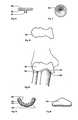
- Fig. 1
- is a plan view of a trochlear template;
- Fig. 2
- is a plan view of a capitellum template;
- Fig. 3
- is a front view of a humeral clamp according to the invention;
- Fig. 4
- is a side view of a humeral clamp of Fig. 3 with an ulna outrigger installed;
- Fig. 5
- is a bottom view of the device of Fig. 4;
- Fig. 6
- is a diagramatic sketch of the device of Fig. 4, in position on an elbow;
- Fig. 7
- is a side view of a humeral cutting cam;
- Fig. 8
- is a plan view of a radius gauge;
- Fig. 9
- is a side view of a radius centre pin cutter;
- Fig. 10
- is a side view of a radial prosthesis;
- Fig. 11
- is a plan view of the prosthesis of Fig. 10;
- Fig. 12
- is a front view of a humeral prosthesis
- Fig. 13
- is a sketch of an anterior view of a right elbow including the humeral, ulnar and radial prosthesis of the present invention;
- Fig. 14
- is a medial view of an ulna prosthesis; and
- Fig. 15
- is an anterior view of the prosthesis of Fig. 14.
- In the copending application filed concurrently herewith a novel humeral resurfacing prosthesis which substantially replicates the distal end of a humerus is described. While it was first thought that the use of external anatomical landmarks, such as the epicondyles, would provide the means to establish the radial centre for the convex semi-circular cut at the distal humerus necessary to receive the prosthesis, this approach was discarded as it was found that the axis (or C-line) of the trochlea and capitellum, which is substantially a straight line, is in fact at an angle of about 2 - 3o to the transepicondylar line (TEL). Instead use is made of the curved surface of the trochlea and capitellum. An incision is made first on the medial side of the elbow and,after drilling a pilot hole in the centre of the medial epicondyle, the epicondylar crown is removed (for later replacement and securement by a screw inserted into the pilot hole). A series of differently sized semi-circular
trochlear templates 10 are placed on the now flattened medial epicondylar plateau to establish, by a "best fit" approach, the geometric centre of the medial aspect of the trochlear, which is then marked and a pilot hole drilled thereat. After making an incision and exposing the lateral side the procedure is repeated with a series ofcapitellum templates 101, which establishes the geometric centre of the capitellum. - A U-shaped width-adjustable
humeral clamp 12 with locatingpins pins pins arms clamp 12 are adjusted towards each other by sliding integral sleeves 151,152 along respective guide rods 153,154 and locked in place by aclamping screw 17 thereby securely locating theclamp 12 and yet still allowing it to be rotated about the C-line axis of the humerus. A humeral cutting cam 18 (Fig. 7) of selected length is axially mounted onshouldered guide pin 42 at the end of themedial arm 15 of theclamp 12 and rotatably secured by means of alocking nut 19 as seen in Fig. 3. Thecam 18 comprises abody 20, having acircular hole 21 therethrough adjacent one end, adapted to be mounted onpin 42 which is in turn arranged to receivelocking nut 19, and about which thebody 20 may be arcuately oscillated, and ahollow guide 22 axially parallel to and spaced a selected distance from thehole 21. Aguide 22 is adapted to receive a rotatable burr (not shown) generally 3,17mm (1/8") in diameter. The burr may be rotated by any conventional power or air tool normally found in an operating theatre. Thecam 18 with the burr in place, oscillated back and forth to ensure that the correct cutting arc has been established. Once the surgeon is satisfied with the cutting arc,cam 18 may be removed if desired. A 2,38mm (3/32") Steinmanpin 24 is then inserted through ahole 23 in theclamp 12 and screwed into the underlying prepared surface of the medial epicondyle. This prevents theclamp 12 from rotating on its axis. A similar Steinman pin may be inserted through acomplementary pilot hole 25 on the lateral side to further assist in rigidly mounting theclamp 12. Theulna fixation assembly 26 is next mounted on thehumeral clamp 12 by means of a U-clamp 27. Theulna fixation assembly 26 comprises a telescopicallyexpandable arm 28, lockable at any selected length by a U-clamp 29. Acrosshead 30 is adjustably and clampingly mounted at the end of thearm 28 by means of acamp 31 intermediate the ends thereof.Coronoid arms arm 28 and to thecrosshead 30 at opposite ends thereof and angularly adjustable relative thereto. Intermediate the ends of thecrosshead 30 there is provided anolecranon bracket 34 which may be locked at any desired angle to thearms screws olecranon bracket 34 is adjusted so that theadjustable pin clamp 37 lies adjacent the olecranon, and a threadedSteinman pin 38 may be inserted throughclamp 37 and drilled not more than about 1 cm into the olecranon so thatpin 38 is substantially parallel to the longitudinal axis of the ulna. With the elbow flexed at about 45o, and held at that angle by a rigid, telescopicallyadjustable bracket 83 andwrist 81 and humeral straps the linked, parallelcoronoid bracket arms medial guide hole 39, drilled through the ulna and into theguide hole 40 on the lateral side. When all the pins are in place and the surgeon is satisfied with the orientation of the ulna and radius relative to the humerus, the adjustment means 26, 27, 31, 35, 36, 37, 41 are locked in place to hold the ulna and humerus in the selected orientation. - A selected
humeral cutting cam 18 is then remounted, if previously removed, on thepin 42 and secured by thenut 19, preparatory to making the humeral cuts. A selected rotatable burr, preferably provided with a depth control gauge (not shown) inserted into thehole 22 and may then be actuated by any conventional air or electric power source. Once inserted, it is preferable to drill to full depth at each extreme of arc. Subsequently, thecam 18 may be moved in either direction, but generally counterclockwise, to remove the remainder of the bone in the trochleal cutting arc, cutting to a depth of about 1 cm at a time and spraying the burr continuously with a sterile saline solution to prevent overheating of the bone and wash away debris. Once the trochleal surface has been removed, and it is here emphasized that the present protocol is designed to remove a minimum of bone stock, the depth control gauge is adjusted to the depth required to cut the capitellum portion, and the capitellum is cut in similar manner to the trochlea. Without removing thecamp 12 from the humerus and ulna, thehumeral cutting cam 18 is removed and replaced with an ulna cutting cam which is similar in shape to humeral cuttingcam 18, but with a slightly larger, and predetermined selected cutting radius. It will be appreciated that, according to our copending application "Elbow Prosthesis" filed concurrently herewith, it has been possible to generate 5 standard sizes of humeral prostheses to fit 95%, of the population. Complementary ulna and radial prostheses of varying thickness are also available, so that the surgeon may select the most suitably sized humeral prostheses and match it with a similarly standardized ulna or radial prosthesis. Thus the clearance required between the humeral and ulna prepared bone surfaces is readily predetermined, and the exact cutting radius for the ulna cutting cam selected. Once selected, positioned and locked in place by thenut 19, the depth gauge is set and cutting of the ulna proceeds in a similar manner to the humeral cut, it being preferred to rotate the ulna cam in a clockwise manner. - The ulna cam is then removed and a flat radius cutting gauge (not shown) is locked in appropriate orientation on the humeral clamp on the
lateral side 16 thereof. Using the flat surface thereof as a guide for an orthopaedic oscillating saw (not shown) the head of the radius is resected. - Any excess bone or cartilage tissue, which might interfere with prosthesis implantation may be trimmed away, from the medial side, by means of selected profile tools and osteotones. Generally such tools may be guided by means of guides (not shown) mounted on the humeral frame. The frame can then be dismounted from the ulna and humerus.
- The arm may then be rotated to the lateral side and a radius gauge 51 (Fig. 8) is selected, from a sized set thereof, which most closely corresponds in diameter to that of the radius and placed over the squarely prepared proximal end of the radius. A marker probe is inserted through
hole 52 and used to mark the centre of the radius. Thegauge 51 is then removed and replaced by radius centre pin cutter 53 (Fig. 9) the centeringpin 54 of which is inserted into the marked centre of the radius. Thecutter 55 is tapped home by means of a small osteotone which is struck againststrike 56. Thecutter 53 is then rotated axially aboutpin 54, in an arc of about 45o in each direction and then removed, thus removing a cylindrical core of bone from the radius. The radial prosthesis 88 (Figs. 10, 11) is then inserted with thestem 81 projecting into the cored hole formed in the radius. The prosthesis is tapped into position by placing the convexly contouredsurface 57 oftool 53 over theconcave surface 89 ofprosthesis 88 and strikingstriker 58 with a small osteotone. - The arm is again rotated to the medial side and the humeral prosthesis 92 (Fig. 12) is inserted into position, as shown in Fig. 13, tapping if required to achieve the desired position and taking care not to disturb the radial prosthesis. The ulna prosthesis 63 (Fig. 14, 15) is then inserted, also from the medial side, and its position adjusted as necessary. Locating pins, if used, are pressed into the underlying ulna bone. Using a bone screw inserted into the predrilled pilot hole, the medial epicondyle is replaced, oriented and secured in place, and after checking to ensure alignment and free movement, the medial and lateral wounds may be closed.
Claims (7)
- An orthopaedic bone positioning and tool guide device for attachment on the distal epicondyles of a human humerus, comprising(a) an adjustable clamping means (12, 17) for transverse pivotal mounting on the epicondyles,(b) first (18) and second cutting tool guide means pivotally mountable for accurate movement on the medial side of the clamp (12), when operatively secured to the humerus, each adapted to receive a cutting tool for accurate bone cutting,
wherein the first guide means (18) has a selected radial length arranged so that the cutting tool cuts the humerus and the second guide means has a selected radial length greater than the first guide means (18) so that the cutting tool cuts the ulna adjacent the humerus,
characterized by(c) extensible arm means (28) mounted on the clamping means (12, 17) and extending longitudinally therefrom, including means (29) to lock the arm means (28) at a selected length;(d) transversely mounted adjustable and lockable means (30, 31) at the free end of the arm means (28), including means to adjustably mount transverse (32, 33) and longitudinal (34, 37) bone securing pins, whereby an ulna may be secured in a preselected orientation relative to the humerus when the clamping means (12, 17) is secured in operative position; and(e) planar cutting tool guide means mountable on the lateral side (16) of the clamping means (12, 17) when operatively secured to the humerus so as to provide a guide for a planar oscillating cutting tool for accurate planar cutting of a radial bone. - The orthopaedic device according to claim 1,
characterized by auxiliary pin locating means (23, 25) on the medial and lateral sides of the clamping means (12, 17) arranged to receive bone pins (24) therethrough to secure the clamping means (12, 17) against rotation on the humerus. - The orthopaedic device according to claim 1 or 2,
characterized by a plurality of trochlear templates (10) of selected sizes each marked with a centre point whereby the centre of the medial epicondyle may be established for mounting the clamping means (12, 17) thereon. - The orthopaedic device according to any of claims 1 to 3,
characterized by a plurality of capitellum templates (101) of selected sizes each marked with a centre point whereby the centre of the lateral epicondyle may be established for mounting the clamping means (12, 17) thereon. - The orthopaedic device according to any of claims 1 to 4,
characterized by a plurality of radial templates (51) of selected sizes each marked with a centre point whereby the centre of a planar resected proximal end of a radius may be determined. - The orthopaedic device according to any of claims 1 to 5,
characterized by a circular radius centre pin cutting device, the cutting device comprising a rigid member (53) having a circular cutter (55) extending perpendicular therefrom and first strike means (56) on the rigid member (53) spaced from and on an opposite side to the cutter (55). - The orthopaedic device according to claim 6,
characterized in that the radius pin cutter further includes a radius prosthesis locating means (5) adjacent the end of the rigid member (53) remote from the cutter (55), and second strike means (58) on the rigid member (53) spaced from and on an opposite side to the cutter (55).
Applications Claiming Priority (2)
| Application Number | Priority Date | Filing Date | Title |
|---|---|---|---|
| US730931 | 1985-05-06 | ||
| US06/730,931US4624250A (en) | 1983-06-24 | 1985-05-06 | Instrument for elbow surface replacement arthroplasty |
Publications (3)
| Publication Number | Publication Date |
|---|---|
| EP0201011A2 EP0201011A2 (en) | 1986-11-12 |
| EP0201011A3 EP0201011A3 (en) | 1987-12-09 |
| EP0201011B1true EP0201011B1 (en) | 1991-08-14 |
Family
ID=24937381
Family Applications (1)
| Application Number | Title | Priority Date | Filing Date |
|---|---|---|---|
| EP86105756AExpiredEP0201011B1 (en) | 1985-05-06 | 1986-04-25 | Orthopaedic device |
Country Status (5)
| Country | Link |
|---|---|
| US (2) | US4624250A (en) |
| EP (1) | EP0201011B1 (en) |
| JP (1) | JPS61255650A (en) |
| CA (1) | CA1248424A (en) |
| DE (1) | DE3680818D1 (en) |
Cited By (2)
| Publication number | Priority date | Publication date | Assignee | Title |
|---|---|---|---|---|
| US6342057B1 (en) | 2000-04-28 | 2002-01-29 | Synthes (Usa) | Remotely aligned surgical drill guide |
| US6379364B1 (en) | 2000-04-28 | 2002-04-30 | Synthes (Usa) | Dual drill guide for a locking bone plate |
Families Citing this family (32)
| Publication number | Priority date | Publication date | Assignee | Title |
|---|---|---|---|---|
| US4624250A (en)* | 1983-06-24 | 1986-11-25 | Queen's University At Kingston | Instrument for elbow surface replacement arthroplasty |
| US5275599A (en)* | 1986-08-11 | 1994-01-04 | Zbikowski Juan L | Biocompression external fixator for osteosynthesis |
| BE1000533A7 (en)* | 1987-05-14 | 1989-01-17 | Georges Emile Ladislas Dury | SURGERY FOR EXTERNAL FIXER-DENTO maxilo-FACIAL. |
| ATE85202T1 (en)* | 1987-10-21 | 1993-02-15 | Smith & Nephew Richards Inc | SURGICAL INSTRUMENT. |
| US5514143A (en)* | 1991-11-27 | 1996-05-07 | Apogee Medical Products, Inc. | Apparatus and method for use during surgery |
| US5616146A (en)* | 1994-05-16 | 1997-04-01 | Murray; William M. | Method and apparatus for machining bone to fit an orthopedic surgical implant |
| US5782922A (en)* | 1997-02-07 | 1998-07-21 | Biomet, Inc. | Method and apparatus for replacing the capitellum |
| US5779709A (en)* | 1997-02-12 | 1998-07-14 | Wright Medical Technology, Inc. | Ulnar cut guide alignment system |
| GB2322304B (en)* | 1997-02-21 | 2001-03-14 | Biomet Ltd | Surgical Tool Aligning Device |
| US6494913B1 (en) | 1998-03-17 | 2002-12-17 | Acumed, Inc. | Shoulder prosthesis |
| US6277123B1 (en) | 1999-09-10 | 2001-08-21 | Depuy Orthopaedics, Inc. | Prosthesis positioning apparatus and method for implanting a prosthesis |
| US6270529B1 (en) | 1999-09-01 | 2001-08-07 | Wright Medical Technology, Inc. | Modular implant for replacing end of radius and having drainage passage for trapped fluid |
| US7635390B1 (en) | 2000-01-14 | 2009-12-22 | Marctec, Llc | Joint replacement component having a modular articulating surface |
| FR2826860B1 (en)* | 2001-07-09 | 2004-03-05 | Tornier Sa | ANCILLARY OF POSITION OF A CUBITAL COMPONENT AND / OR A RADIAL COMPONENT OF ELBOW PROSTHESIS |
| FR2826859B1 (en)* | 2001-07-09 | 2003-09-19 | Tornier Sa | ANCILLARY OF LAYING OF A HUMERAL COMPONENT OF ELBOW PROSTHESIS |
| US7708741B1 (en) | 2001-08-28 | 2010-05-04 | Marctec, Llc | Method of preparing bones for knee replacement surgery |
| US6945976B2 (en)* | 2002-03-29 | 2005-09-20 | Depuy Products, Inc. | Method and apparatus for resecting bone from an ulna in preparation for prosthetic implantation |
| US7452381B2 (en)* | 2003-01-30 | 2008-11-18 | Mayo Foundation For Medical Education And Research | Radial head replacement system |
| US7160329B2 (en)* | 2004-12-01 | 2007-01-09 | Mayo Foundation For Medical Research And Education | Radial-capitellar implant |
| WO2006127146A2 (en)* | 2005-04-25 | 2006-11-30 | University Of Maryland, Baltimore | Coronoid process fracture fixator |
| US8012214B2 (en)* | 2005-09-27 | 2011-09-06 | Randall Lane Acker | Joint prosthesis |
| US8034113B2 (en) | 2005-09-27 | 2011-10-11 | Randall Lane Acker | Joint prosthesis and method of implanting same |
| US12310602B2 (en) | 2005-09-27 | 2025-05-27 | Bioshift, Llc | Milling apparatus for implanting a joint prosthesis |
| WO2008098250A2 (en)* | 2007-02-10 | 2008-08-14 | Small Bone Innovations, Inc. | Radial head implant and related instrument |
| EP3610809B1 (en)* | 2009-01-23 | 2021-07-14 | Synthes GmbH | Jig and saw guides for use in osteotomies |
| WO2011066023A1 (en)* | 2009-08-03 | 2011-06-03 | Skeletal Dynamics Llc | Internal joint stabilizer device, system and method of use |
| US20110218532A1 (en)* | 2010-03-03 | 2011-09-08 | Eglseder W Andrew | Coronoid fracture fixation device |
| US9770272B2 (en) | 2012-12-12 | 2017-09-26 | Wright Medical Technology, Inc. | Orthopedic compression/distraction device |
| EP3273877B1 (en) | 2015-03-25 | 2019-05-22 | E. Marlowe Goble | Knee instruments and methods |
| US10568650B2 (en) | 2015-03-25 | 2020-02-25 | E. Marlowe Goble | Knee instruments and methods |
| RU177840U1 (en)* | 2017-08-10 | 2018-03-14 | Федеральное государственное автономное образовательное учреждение высшего образования "Крымский федеральный университет имени В.И. Вернадского" | Drill guide for osteotomy of tubular bones |
| US11234720B2 (en) | 2018-03-07 | 2022-02-01 | E. Marlowe Goble | Knee instruments and methods |
Family Cites Families (17)
| Publication number | Priority date | Publication date | Assignee | Title |
|---|---|---|---|---|
| US3547115A (en)* | 1968-04-05 | 1970-12-15 | Peter S Stevens | Osteoarticular prosthetic method |
| US3868730A (en)* | 1973-09-24 | 1975-03-04 | Howmedica | Knee or elbow prosthesis |
| SU517196A1 (en)* | 1974-07-22 | 1977-09-25 | Центральный Ордена Трудового Красного Знамени Научно-Исследовательского Институт Травматологии И Ортопедии | Apparatus for repositioning and fixing bone fragments |
| SU577020A1 (en)* | 1976-06-08 | 1977-10-25 | Центральный Ордена Трудового Красного Знамени Научно-Исследовательский Институт Травматологии И Ортопедии Им. Н.Н.Приорова | Device for working ends of joints |
| US4100626A (en)* | 1977-04-29 | 1978-07-18 | Ontario Research Foundation | Wrist implant apparatus |
| GB1601576A (en)* | 1977-06-01 | 1981-10-28 | Howmedica | Elbow prosthesis |
| DE2811331A1 (en)* | 1978-03-16 | 1979-09-27 | Schuett & Grundei Sanitaet | ELBOW JOINT IN THE FORM OF A FULL ENDO-PROSTHESIS |
| JPS5526987A (en)* | 1978-05-31 | 1980-02-26 | Wadsworth Thomas G | Elbow replacement prosthetic dentistry device |
| US4257411A (en)* | 1979-02-08 | 1981-03-24 | Cho Kenneth O | Cruciate ligament surgical drill guide |
| US4409973A (en)* | 1981-01-29 | 1983-10-18 | Neufeld John A | Method and apparatus for corrective osteotomy |
| DE3223925C2 (en)* | 1982-06-26 | 1986-07-31 | Feldmühle AG, 4000 Düsseldorf | Implantable elbow joint |
| US4457307A (en)* | 1982-08-20 | 1984-07-03 | Stillwell William T | Bone cutting device for total knee replacement |
| NZ205096A (en)* | 1982-09-10 | 1986-03-14 | Univ Kingston | Mounting apparatus for bone cutting device |
| DE3470456D1 (en)* | 1983-06-24 | 1988-05-26 | Univ Kingston | Apparatus for locating an elbow prothesis |
| US4624250A (en)* | 1983-06-24 | 1986-11-25 | Queen's University At Kingston | Instrument for elbow surface replacement arthroplasty |
| US4565192A (en)* | 1984-04-12 | 1986-01-21 | Shapiro James A | Device for cutting a patella and method therefor |
| US4574794A (en)* | 1984-06-01 | 1986-03-11 | Queen's University At Kingston | Orthopaedic bone cutting jig and alignment device |
- 1985
- 1985-05-06USUS06/730,931patent/US4624250A/ennot_activeExpired - Fee Related
- 1986
- 1986-04-25EPEP86105756Apatent/EP0201011B1/ennot_activeExpired
- 1986-04-25CACA000507680Apatent/CA1248424A/ennot_activeExpired
- 1986-04-25DEDE8686105756Tpatent/DE3680818D1/ennot_activeExpired - Lifetime
- 1986-05-02JPJP61101199Apatent/JPS61255650A/enactivePending
- 1986-08-07USUS06/894,214patent/US4718414A/ennot_activeExpired - Lifetime
Cited By (2)
| Publication number | Priority date | Publication date | Assignee | Title |
|---|---|---|---|---|
| US6342057B1 (en) | 2000-04-28 | 2002-01-29 | Synthes (Usa) | Remotely aligned surgical drill guide |
| US6379364B1 (en) | 2000-04-28 | 2002-04-30 | Synthes (Usa) | Dual drill guide for a locking bone plate |
Also Published As
| Publication number | Publication date |
|---|---|
| CA1248424A (en) | 1989-01-10 |
| EP0201011A3 (en) | 1987-12-09 |
| JPS61255650A (en) | 1986-11-13 |
| DE3680818D1 (en) | 1991-09-19 |
| US4624250A (en) | 1986-11-25 |
| EP0201011A2 (en) | 1986-11-12 |
| US4718414A (en) | 1988-01-12 |
Similar Documents
| Publication | Publication Date | Title |
|---|---|---|
| EP0201011B1 (en) | Orthopaedic device | |
| US6945976B2 (en) | Method and apparatus for resecting bone from an ulna in preparation for prosthetic implantation | |
| US12178453B2 (en) | Alignment instruments and methods for use in total ankle replacement | |
| AU696251B2 (en) | Distal femoral cutting guide | |
| US5122144A (en) | Method and instrumentation for unicompartmental total knee arthroplasty | |
| EP0460886B1 (en) | Intramedullary referenced humeral head resection guide | |
| US5234433A (en) | Method and instrumentation for unicompartmental total knee arthroplasty | |
| US4935023A (en) | Femoral surface shaping guide for knee implants | |
| CA1211331A (en) | Method and apparatus for shaping a distal femoral surface | |
| JP2560101B2 (en) | Bone cutting guide and its use | |
| CA1211330A (en) | Method and apparatus for shaping a distal femoral surface | |
| NZ307151A (en) | Instruments for the adjustment osteotomy of a lower extremity, surgical saw guides | |
| CA2007359A1 (en) | Tibial surface shaping guide for knee implants | |
| CA1232405A (en) | Elbow prosthesis | |
| EP1836975B1 (en) | A surgical instrument for locating a cutting plane on a bone |
Legal Events
| Date | Code | Title | Description |
|---|---|---|---|
| PUAI | Public reference made under article 153(3) epc to a published international application that has entered the european phase | Free format text:ORIGINAL CODE: 0009012 | |
| AK | Designated contracting states | Kind code of ref document:A2 Designated state(s):CH DE FR GB LI | |
| PUAL | Search report despatched | Free format text:ORIGINAL CODE: 0009013 | |
| AK | Designated contracting states | Kind code of ref document:A3 Designated state(s):CH DE FR GB LI | |
| 17P | Request for examination filed | Effective date:19880607 | |
| 17Q | First examination report despatched | Effective date:19900302 | |
| GRAA | (expected) grant | Free format text:ORIGINAL CODE: 0009210 | |
| AK | Designated contracting states | Kind code of ref document:B1 Designated state(s):CH DE FR GB LI | |
| ET | Fr: translation filed | ||
| REF | Corresponds to: | Ref document number:3680818 Country of ref document:DE Date of ref document:19910919 | |
| PG25 | Lapsed in a contracting state [announced via postgrant information from national office to epo] | Ref country code:GB Effective date:19920425 | |
| PG25 | Lapsed in a contracting state [announced via postgrant information from national office to epo] | Ref country code:LI Effective date:19920430 Ref country code:CH Effective date:19920430 | |
| PLBE | No opposition filed within time limit | Free format text:ORIGINAL CODE: 0009261 | |
| STAA | Information on the status of an ep patent application or granted ep patent | Free format text:STATUS: NO OPPOSITION FILED WITHIN TIME LIMIT | |
| 26N | No opposition filed | ||
| GBPC | Gb: european patent ceased through non-payment of renewal fee | ||
| PG25 | Lapsed in a contracting state [announced via postgrant information from national office to epo] | Ref country code:FR Effective date:19921230 | |
| REG | Reference to a national code | Ref country code:CH Ref legal event code:PL | |
| PG25 | Lapsed in a contracting state [announced via postgrant information from national office to epo] | Ref country code:DE Effective date:19930101 | |
| REG | Reference to a national code | Ref country code:FR Ref legal event code:ST |