EP0195393A2 - Differential actuator - Google Patents
Differential actuatorDownload PDFInfo
- Publication number
- EP0195393A2 EP0195393A2EP86103533AEP86103533AEP0195393A2EP 0195393 A2EP0195393 A2EP 0195393A2EP 86103533 AEP86103533 AEP 86103533AEP 86103533 AEP86103533 AEP 86103533AEP 0195393 A2EP0195393 A2EP 0195393A2
- Authority
- EP
- European Patent Office
- Prior art keywords
- bevel gears
- differential
- unit actuators
- actuator according
- actuator
- Prior art date
- Legal status (The legal status is an assumption and is not a legal conclusion. Google has not performed a legal analysis and makes no representation as to the accuracy of the status listed.)
- Granted
Links
Images


Classifications
- B—PERFORMING OPERATIONS; TRANSPORTING
- B25—HAND TOOLS; PORTABLE POWER-DRIVEN TOOLS; MANIPULATORS
- B25J—MANIPULATORS; CHAMBERS PROVIDED WITH MANIPULATION DEVICES
- B25J11/00—Manipulators not otherwise provided for
- F—MECHANICAL ENGINEERING; LIGHTING; HEATING; WEAPONS; BLASTING
- F16—ENGINEERING ELEMENTS AND UNITS; GENERAL MEASURES FOR PRODUCING AND MAINTAINING EFFECTIVE FUNCTIONING OF MACHINES OR INSTALLATIONS; THERMAL INSULATION IN GENERAL
- F16H—GEARING
- F16H3/00—Toothed gearings for conveying rotary motion with variable gear ratio or for reversing rotary motion
- F16H3/44—Toothed gearings for conveying rotary motion with variable gear ratio or for reversing rotary motion using gears having orbital motion
- F16H3/72—Toothed gearings for conveying rotary motion with variable gear ratio or for reversing rotary motion using gears having orbital motion with a secondary drive, e.g. regulating motor, in order to vary speed continuously
- F16H3/724—Toothed gearings for conveying rotary motion with variable gear ratio or for reversing rotary motion using gears having orbital motion with a secondary drive, e.g. regulating motor, in order to vary speed continuously using externally powered electric machines
Definitions
- the present inventionrelates to an actuator and more particularly to a structure of an integral type differential actuator comprising two unit actuators and a differential mechanism, capable of attaining a wide speed range from zero to a desired speed.
- the actuator of the present inventionis advantageously applicable as a drive source for arm of an industrial robot
- Fig. 8One of the generally known differential actuators is shown in Fig. 8, in which the reference numeral 61 denotes an electric motor; numeral 62 denotes a coupling attached to a shaft end of the motor 61; numeral 63 denotes an input shaft connected to the coupling 62; numeral 64 denotes an input-side gear mounted on a fore end of the input shaft 63; and numeral 65 denotes a differential gear attached to a box 66 through a bearing, the rotation of the box 66 being controlled by a speed governor 67 which is in contact with a contact member 66a. Numeral 68 denotes a bearing which supports the box rotatably, and numeral 69 denotes an output-side gear mounted on a fore end of an output shaft 70 and connected to the differential gear 65.
- a DC motoris used as it is as a single body and the speed is changed by controlling the armature voltage or the field current, or alternatively the input-side gear 64 is rotated by the motor 61 connected to the input shaft 63 through the coupling 62 as shown in the figure to thereby rotate the differential gear 65 connected to the gear 64.
- the differential gear 65not only rotates on its own axis but also rotates together with the box 66 because it is connected to the box. Therefore, the speed of the box 66 can be controlled by changing the peripheral speed of the speed governor 67 and consequently the rotating speed of the output shaft 70 is controlled through the output-side gear 69.
- the speed control rangeis practically not larger than 1 : 3000 and problems such as torque ripple at low speeds and backlash have been involved therein.
- ftis an object of the present invention to provide an improved differential actuator free of such drawbacks as torque ripple at slow rotation and backlash at the time of forward-reverse switching.
- a differential actuatorin one aspect of the present invention, includes first and second unit actuators each having a rotational shaft capable of being rotated in a forward or reverse direction at a desired speed; a housing which accommodates therein first and second unit actuators so that the rotational shafts of the unit actuators are aligned with and opposed to each other at ends thereof with a predetermined spacing; and a differential mechanism connected to the rotational shafts of the first and second unit actuators and functioning to rotate an output member at a speed corresponding to a relative rotating speed difference between the two rotational shafts.
- the differential mechanismis provided with
- the differential gearsare interconnected rotatably about their own axes and also rotatably along a circle, the center of which is disposed at the rotational center of the bevel gears. The rotation of the differential gears along the circle is taken out as an output of the differential actuator.
- the output thereofcorresponds to the difference in the rotational speed between the two unit actuators, the speed ranges from zero to an upper limit of one of the unit actuators, thus theoretically having an infinitely large speed control ratio. Besides, even when the output shaft is at zero speed, the unit actuator rotating high speeds and hence, there is no fear of seizure of the unit actuators and also a torque ripple at a low speed scarcely appears on the output shaft
- a differential actuator according to the present inventionis shown in Fig. 1, in which the reference numerals 1 and 2 denote first and second unit actuators having first and second drive shafts 3 and 4 which are located on the same axis l1 and opposed to each other with a predetermined space therebetween.
- Numeral 5denotes a control means for controlling the first and second unit actuators to rotate the first and second drive shafts 3 and 4 in forward and reverse directions and also at a variable rotating speed.
- Numerals 6 and 7denote first and second bevel gears fixed at ends of the first and second drive shafts 3 and 4, respectively, the bevel gears 6 and 7 being formed in the same shape and same size.
- Numerals 8 and 9represent a pair of bevel gears or a third bevel gears assembly which are positioned on an axis l2 perpendicular to the axis l and which are in mesh with the bevel gears 6 and 7.
- the bevel gears 8 and 9are centrally formed with axially extending holes 8A and 9A.
- Numeral 10denotes a ring-like differential belt pulley. As best shown in Fig. 2, a pair of radially inwardly extending engaging shafts 11 and 1 2 are formed oppositely on an inner peripheral surface of the differential belt pulley 10. The engaging shafts 11 and 12 are engaged with bearings 13 and 14 mounted in the holes 8A and 9A of the bevel gears 8 and 9 to support the bevel gears rotatably.
- a differential mechanism 15is constituted by the bevel gears 6, 7, 8, 9, differential belt pulley 10 and engaging shafts 11, 12. It transmits power to the driven side through a belt (not shown) passed round the belt pulley 10, at a rotating speed corresponding to the sum or difference of the rotating speeds of the drive shafts 3 and 4. These components are enclosed in a housing 16 to constitute a single actuator.
- the actuator constructed as aboveoperates in the following manner.
- the bevel gears 8 and 9will not rotate (on their own axes) but revolve in mesh with the first and second bevel gears 6 and 7 as if they were integral with those first and second bevel gears, and the differential belt pulley 10 will also rotate integrally with them.
- the output value during rotationis equal to the sum of outputs of both unit actuators 1 and 2.
- a desired rotational speed of the output shaftis obtained by combining the rotational directions of the first and second drive shafts 3 and 4 with the difference in rotational speed between the two, there can be attained a good response characteristic in obtaining the desired speed.
- Fig. 3there is illustrated a modified embodiment of the present invention, in which two unit actuators 1 and 2, which may be the same as in Fig. 1, have hollow shafts 21 and 22, respectively, and are disposed within a housing 16 so that the hollow shafts 21 and 22 are in alignment with each other.
- a differential mechanism 15 used hereinhas a function equal to that of the differential mechanism used in the actuator of Fig. 1, but is different from the latter in that bevel gears 8 and 9 are supported not by a belt pulley but by both ends of a differential shaft 23.
- the differential shaft 23is fixedly connected to an output shaft 24 which extends through the bores of the hollow shafts 21 and 22 and which are supported by the housing 16.
- the difference in rotational speed between the bevel gears 6 and 7brings about rotation of the differential shaft 23 about the axis of the bevel gears 6 and 7 at a speed proportional to the value of such difference, and this rotation is transmitted to the output shaft 2 4 .
- each of the actuators 1 and 2may be constituted by a motor which also serves as a generator when the rotational shaft is forcibly rotated with an externally power.
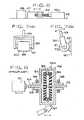
- Figs. 4(A) and 4(B)which illustrate an actuator having such type of motors as unit actuators 1 and 2
- the first unit actuator 1is provided with a field circuit 31 and an armature 32, the armature 32 being electrically connected to terminals indicated at T1
- the second actuator 2is provided with a field circuit 33 and an armature 34, the armature 34 being electrically connected to terminals indicated at T2.
- the operation of the actuatorwill now be explained in the case where a power generation controlling resistor 35 is connected to the terminals T1 and a power supply circuit 36 consisting of an AC source and a rectifier circuit is connected to the terminals T2.
- a power generation controlling resistor 35is connected to the terminals T1 and a power supply circuit 36 consisting of an AC source and a rectifier circuit is connected to the terminals T2.
- any of the power generation controlling resistor and the power supply circuitmay be connected to the terminals T1 and T2. Therefore, the actuator can be operated in one of the following four operation modes:
- Fig. 4(B)corresponds to mode 3.
- mode 3where the rotational speeds of the first and second unit actuators 1 and 2 are equal to each other, the rotational speed of the output shaft 24 is zero and its output torque is maximum.
- Fig. 5shows an example in which the actuator 100 of the invention is used for driving a main shaft 41. of an electrical discharge machine.
- the main shaft 41is connected to the output shaft of the actuator 100 through a ball screw 42 and it is capable of approaching and going away from a work 44 supported on a head 43.
- the rise-fall speed ratio of the main shaft during electrical discharge machiningis required to be about 10,000, which is satisfied by the actuator of the present invention.
- Fig. 6shows an example in which the actuator 100 of the invention is applied to a pusher in a conventional automatic machine.
- the actuator 100is fixed to a base 45 and it acts to push out a work 48 to a desired position through a head 47 which is connected to the output shaft of the actuator through a ball screw 46.
- Such operations as slowing moving the head 47 forward and rapidly moving it backwardcan be realized easily
- Figs. 7(A) and 7(B)show an articular portion of an industrial robot provided with the actuator 100 of the invention-
- the actuator 100is fixed to a suitable base 50 through a bracket 49.
- An output shaft 51 of the actuatoris fixedly connected to a bracket 52, and by its rotation in one direction or an opposite direction about the axis thereof, the bracket 52 and arm 53 attached thereto are swung.
- the actuator of the present inventionpermits rotation of its output shaft in any desired direction at any desired speed, and its output torque can be adjusted in a wide range.
Landscapes
- Engineering & Computer Science (AREA)
- General Engineering & Computer Science (AREA)
- Mechanical Engineering (AREA)
- Robotics (AREA)
- Retarders (AREA)
- Manipulator (AREA)
- Soil Working Implements (AREA)
- Connection Of Motors, Electrical Generators, Mechanical Devices, And The Like (AREA)
Abstract
Description
- The present invention relates to an actuator and more particularly to a structure of an integral type differential actuator comprising two unit actuators and a differential mechanism, capable of attaining a wide speed range from zero to a desired speed. The actuator of the present invention is advantageously applicable as a drive source for arm of an industrial robot
- One of the generally known differential actuators is shown in Fig. 8, in which the
reference numeral 61 denotes an electric motor; numeral 62 denotes a coupling attached to a shaft end of themotor 61;numeral 63 denotes an input shaft connected to thecoupling 62;numeral 64 denotes an input-side gear mounted on a fore end of theinput shaft 63; and numeral 65 denotes a differential gear attached to abox 66 through a bearing, the rotation of thebox 66 being controlled by aspeed governor 67 which is in contact with acontact member 66a.Numeral 68 denotes a bearing which supports the box rotatably, and numeral 69 denotes an output-side gear mounted on a fore end of anoutput shaft 70 and connected to thedifferential gear 65. - In speed control, for example in the case of a thyristor Leonard, a DC motor is used as it is as a single body and the speed is changed by controlling the armature voltage or the field current, or alternatively the input-
side gear 64 is rotated by themotor 61 connected to theinput shaft 63 through thecoupling 62 as shown in the figure to thereby rotate thedifferential gear 65 connected to thegear 64. At this time, thedifferential gear 65 not only rotates on its own axis but also rotates together with thebox 66 because it is connected to the box. Therefore, the speed of thebox 66 can be controlled by changing the peripheral speed of thespeed governor 67 and consequently the rotating speed of theoutput shaft 70 is controlled through the output-side gear 69. - Since the conventional actuator as a speed change mechanism is constructed as above, the speed control range is practically not larger than 1 : 3000 and problems such as torque ripple at low speeds and backlash have been involved therein.
- ft is an object of the present invention to provide an improved differential actuator free of such drawbacks as torque ripple at slow rotation and backlash at the time of forward-reverse switching.
- In one aspect of the present invention, a differential actuator includes first and second unit actuators each having a rotational shaft capable of being rotated in a forward or reverse direction at a desired speed; a housing which accommodates therein first and second unit actuators so that the rotational shafts of the unit actuators are aligned with and opposed to each other at ends thereof with a predetermined spacing; and a differential mechanism connected to the rotational shafts of the first and second unit actuators and functioning to rotate an output member at a speed corresponding to a relative rotating speed difference between the two rotational shafts.
- Preferably, the differential mechanism is provided with
- two bevel gears mounted on the two unit actuators in a coaxially opposed relation to each other, and also provided with two differential gears each engaged with the bevel gears. The differential gears are interconnected rotatably about their own axes and also rotatably along a circle, the center of which is disposed at the rotational center of the bevel gears. The rotation of the differential gears along the circle is taken out as an output of the differential actuator.
- In the actuator of the invention, since the output thereof corresponds to the difference in the rotational speed between the two unit actuators, the speed ranges from zero to an upper limit of one of the unit actuators, thus theoretically having an infinitely large speed control ratio. Besides, even when the output shaft is at zero speed, the unit actuator rotating high speeds and hence, there is no fear of seizure of the unit actuators and also a torque ripple at a low speed scarcely appears on the output shaft
- Fig. 1 is a longitudinal sectional view of a differential actuator according to the present invention;
- Fig. 2 is a perspective view of a differential belt pulley used in the actuator of Fig.1;
- Fig. 3 is a longitudinal sectional view of another differential actuator according to the present invention;
- Fig. 4(A) is a plan view of the actuator shown in Fig. 3;
- Fig. 4(B) illustrates an electrical connection of the actuator shown in Figs. 3 and 4(A);
- Fig. 5 is a schematic plan view of the actuator of the invention as applied to driving a main shaft of an electrical discharge machine;
- Fig. 6 is a schematic side view of the actuator of the invention as applied to a pusher;
- Fig. 7(A) is a front view showing an example of using the actuator of the invention for driving a robot arm;
- Fig. 7(B) is a side view thereof; and
- Fig. 8 is a longitudinal sectional view of a conventional differential actuator.
- Referring to the drawings, a differential actuator according to the present invention is shown in Fig. 1, in which the
reference numerals second drive shafts second drive shafts Numerals 6 and 7 denote first and second bevel gears fixed at ends of the first andsecond drive shafts bevel gears 6 and 7 being formed in the same shape and same size.Numerals 8 and 9 represent a pair of bevel gears or a third bevel gears assembly which are positioned on an axis ℓ2 perpendicular to the axis ℓ and which are in mesh with thebevel gears 6 and 7. Thebevel gears 8 and 9 are centrally formed with axially extending holes 8A and 9A.- Numeral 10 denotes a ring-like differential belt pulley. As best shown in Fig. 2, a pair of radially inwardly extending
engaging shafts differential belt pulley 10. Theengaging shafts bearings bevel gears 8 and 9 to support the bevel gears rotatably. - A
differential mechanism 15 is constituted by thebevel gears differential belt pulley 10 andengaging shafts belt pulley 10, at a rotating speed corresponding to the sum or difference of the rotating speeds of thedrive shafts housing 16 to constitute a single actuator. - The actuator constructed as above operates in the following manner.
- It is here assumed that the rotational direction of the
first drive shaft 3 and that of thesecond drive shaft 4 are the same, that is, the two are rotating in opposite directions with respect to thedifferential mechanism 15. If the rotating speed of thefirst drive shaft 3 is 8A and that of thesecond drive shaft 4 is 8B, 9A being larger than 6B, thebevel gears 8 and 9 revolve along the peripheral edge of thebevel gear 7 while rotating on their own axes on the basis of a relative difference of the speeds θA and 6B, so that the differential belt pulley10 rotates at the same speed as the revolving speed of thebevel gears 8 and 9. In this case, the rotating speed of thebelt pulley 10, namely, the speed θo taken out from thedifferential mechanism 15, is obtained from the following equation (1):
- Where 8A is smaller than θB, the
differential belt pulley 10 rotates in a direction opposite to the above, so that thedifferential mechanism 15 outputs a rotational speed in a direction reverse to the above. When the rotating speeds of thedrive shafts differential mechanism 15 becomes zero, that is, the rotation stops. Thus, even when thedrive shafts drive shafts differential mechanism 15, the speeds eA, θB and θo are in the following relationship (2):
- From the above equation (2) it is seen that if a drive shaft (e.g. the first drive shaft 3) rotating at a low speed and a drive shaft (4) rotating at a high speed are combined, the rotating speed is increased an amount corresponding to the sum of the two.
- On the other hand, if the rotational speeds 0A and 6B of the first and
second drive shafts bevel gears 8 and 9 will not rotate (on their own axes) but revolve in mesh with the first andsecond bevel gears 6 and 7 as if they were integral with those first and second bevel gears, and thedifferential belt pulley 10 will also rotate integrally with them. The output value during rotation is equal to the sum of outputs of bothunit actuators - As is apparent from the above, the speed change range of the differential actuator is such a wide range as shown by the following equation (3):

- Moreover, since a desired rotational speed of the output shaft is obtained by combining the rotational directions of the first and
second drive shafts - Referring now to Fig. 3, there is illustrated a modified embodiment of the present invention, in which two
unit actuators hollow shafts housing 16 so that thehollow shafts differential mechanism 15 used herein has a function equal to that of the differential mechanism used in the actuator of Fig. 1, but is different from the latter in thatbevel gears 8 and 9 are supported not by a belt pulley but by both ends of adifferential shaft 23. Thedifferential shaft 23 is fixedly connected to anoutput shaft 24 which extends through the bores of thehollow shafts housing 16. - In the embodiment of Fig. 3, the difference in rotational speed between the
bevel gears 6 and 7 brings about rotation of thedifferential shaft 23 about the axis of thebevel gears 6 and 7 at a speed proportional to the value of such difference, and this rotation is transmitted to theoutput shaft 24. - In both embodiments described above, each of the
actuators unit actuators first unit actuator 1 is provided with afield circuit 31 and anarmature 32, thearmature 32 being electrically connected to terminals indicated at T1, and thesecond actuator 2 is provided with afield circuit 33 and anarmature 34, thearmature 34 being electrically connected to terminals indicated at T2. As an example, the operation of the actuator will now be explained in the case where a powergeneration controlling resistor 35 is connected to the terminals T1 and apower supply circuit 36 consisting of an AC source and a rectifier circuit is connected to the terminals T2. Provided, however, that any of the power generation controlling resistor and the power supply circuit may be connected to the terminals T1 and T2. Therefore, the actuator can be operated in one of the following four operation modes:
- The arrangement of Fig. 4(B) corresponds to
mode 3. Inmode 3, where the rotational speeds of the first andsecond unit actuators output shaft 24 is zero and its output torque is maximum. - The actuator of the present invention can be utilized in an extremely wide range of use. Fig. 5 shows an example in which the
actuator 100 of the invention is used for driving amain shaft 41. of an electrical discharge machine. Themain shaft 41 is connected to the output shaft of theactuator 100 through aball screw 42 and it is capable of approaching and going away from awork 44 supported on ahead 43. The rise-fall speed ratio of the main shaft during electrical discharge machining is required to be about 10,000, which is satisfied by the actuator of the present invention. - Fig. 6 shows an example in which the
actuator 100 of the invention is applied to a pusher in a conventional automatic machine. Theactuator 100 is fixed to abase 45 and it acts to push out a work 48 to a desired position through a head 47 which is connected to the output shaft of the actuator through aball screw 46. Such operations as slowing moving the head 47 forward and rapidly moving it backward can be realized easily - Further, Figs. 7(A) and 7(B) show an articular portion of an industrial robot provided with the
actuator 100 of the invention- Theactuator 100 is fixed to asuitable base 50 through abracket 49. Anoutput shaft 51 of the actuator is fixedly connected to abracket 52, and by its rotation in one direction or an opposite direction about the axis thereof, thebracket 52 andarm 53 attached thereto are swung. - In the application examples shown in Figs. 5, 6, 7(A) and 7(B) and all of the possible application examples similar thereto, the actuator of the present invention permits rotation of its output shaft in any desired direction at any desired speed, and its output torque can be adjusted in a wide range.


Claims (8)
Applications Claiming Priority (4)
| Application Number | Priority Date | Filing Date | Title |
|---|---|---|---|
| JP5506985AJPS61215833A (en) | 1985-03-19 | 1985-03-19 | Differential actuator |
| JP55069/85 | 1985-03-19 | ||
| JP55070/85 | 1985-03-19 | ||
| JP60055070AJPS61215836A (en) | 1985-03-19 | 1985-03-19 | Control method of differential actuator |
Publications (3)
| Publication Number | Publication Date |
|---|---|
| EP0195393A2true EP0195393A2 (en) | 1986-09-24 |
| EP0195393A3 EP0195393A3 (en) | 1987-06-16 |
| EP0195393B1 EP0195393B1 (en) | 1990-10-24 |
Family
ID=26395919
Family Applications (1)
| Application Number | Title | Priority Date | Filing Date |
|---|---|---|---|
| EP86103533AExpired - LifetimeEP0195393B1 (en) | 1985-03-19 | 1986-03-15 | Differential actuator |
Country Status (5)
| Country | Link |
|---|---|
| US (1) | US4729258A (en) |
| EP (1) | EP0195393B1 (en) |
| KR (1) | KR890000735B1 (en) |
| CA (1) | CA1260732A (en) |
| DE (1) | DE3675041D1 (en) |
Cited By (6)
| Publication number | Priority date | Publication date | Assignee | Title |
|---|---|---|---|---|
| WO1994013979A1 (en)* | 1992-12-08 | 1994-06-23 | Licexia, Spolecnost S Rucením Omezenym | Power gear assembly |
| WO1998031952A1 (en)* | 1997-01-16 | 1998-07-23 | He Holdings, Inc. Dba Hughes Electronics | Dual-drive three-speed differential transmission for gimbal actuator |
| CN104254967B (en)* | 2012-02-08 | 2017-01-18 | 雷米技术有限公司 | Center adapter assembly |
| WO2018090985A1 (en)* | 2016-11-17 | 2018-05-24 | 郑州宇通客车股份有限公司 | Vehicle, power system of same, and motor-gearbox-motor power unit thereof |
| ES2677694A1 (en)* | 2017-02-06 | 2018-08-06 | Universidad De Castilla La Mancha | POINT OF DEVICE (Machine-translation by Google Translate, not legally binding) |
| CN112454416A (en)* | 2020-10-26 | 2021-03-09 | 深圳市优必选科技股份有限公司 | Servo steering wheel module and robot |
Families Citing this family (17)
| Publication number | Priority date | Publication date | Assignee | Title |
|---|---|---|---|---|
| US5067932A (en)* | 1990-11-28 | 1991-11-26 | Edwards Jonathan R | Dual-input infinite-speed integral motor and transmission device |
| US5396968A (en)* | 1992-03-18 | 1995-03-14 | Aisin Aw Co., Ltd. | Drive mechanism for electric car |
| US5512022A (en)* | 1993-10-26 | 1996-04-30 | Suzuki; Naruhito | Motor mechanism |
| US5575730A (en)* | 1994-05-20 | 1996-11-19 | Edwards; Jonathan | Multiple-input infinite-speed integral motor and transmission device |
| US5508574A (en)* | 1994-11-23 | 1996-04-16 | Vlock; Alexander | Vehicle transmission system with variable speed drive |
| DE19842976A1 (en)* | 1998-09-19 | 2000-03-23 | Bayerische Motoren Werke Ag | Control system for adjusting element of vehicle to which are assigned two power sources for adjustment in two working directions and both power sources deliver continuous output |
| US20040025826A1 (en)* | 2002-08-08 | 2004-02-12 | Grosh Charles Reed | Variable geometry engine, arranged from two identical internal combustion engines |
| JP2004316847A (en)* | 2003-04-18 | 2004-11-11 | Toyota Industries Corp | Differential device |
| US20100304920A1 (en)* | 2009-05-28 | 2010-12-02 | Bernard Joseph Simon | Hybrid Assembly , A Hybrid Power-Train , And A Method For Operating A SelectivelyMovable Assembly |
| CN101596860B (en)* | 2009-07-24 | 2013-02-13 | 上海中上汽车科技有限公司 | Split differential motor drive axle |
| US8686680B2 (en)* | 2011-06-13 | 2014-04-01 | Rethink Robotics, Inc. | Dual-motor series elastic actuator |
| EP2740970A1 (en)* | 2011-08-04 | 2014-06-11 | Kabushiki Kaisha Yaskawa Denki | Composite drive device and robot |
| US8742711B2 (en) | 2011-09-22 | 2014-06-03 | Honeywell International Inc. | Active feedback user interface system and gimbal assembly therefor |
| US9409298B2 (en) | 2012-04-13 | 2016-08-09 | Rethink Robotics, Inc. | Flexure elements for series elastic actuators and related methods |
| US9441599B2 (en) | 2012-07-17 | 2016-09-13 | Altigreen Propulsion Labs Private Limited | Induction motor-permanent magnet generator tandem configuration starter-generator for hybrid vehicles |
| US9580065B2 (en)* | 2012-07-17 | 2017-02-28 | Altigreen Propulsion Labs Private Limited | Dual-structured electric drive and power system for hybrid vehicles |
| KR101889792B1 (en)* | 2017-07-03 | 2018-08-20 | 김석준 | In-wheel driving apparatus for electric vehicle |
Family Cites Families (17)
| Publication number | Priority date | Publication date | Assignee | Title |
|---|---|---|---|---|
| DE356516C (en)* | 1922-07-21 | Nicolae Iliescu Branceni | Three-phase or single-phase motor unit | |
| GB190801041A (en)* | 1908-01-16 | 1909-01-18 | Wilfrid L Spence | Variable Speed Gear. |
| US981689A (en)* | 1909-07-20 | 1911-01-17 | Universal Motor Company | Differential-speed mechanism. |
| DE335176C (en)* | 1919-04-26 | 1921-04-04 | Aktienver Fuer Bergbau Und Hue | Device for regulating the speed of several motors serving for a common drive of any device |
| US1706276A (en)* | 1926-12-21 | 1929-03-19 | Zweigbergk Thorsten | Electric transmission system |
| US2330821A (en)* | 1939-06-16 | 1943-10-05 | Finzi Umberto | Gradual speed changing device |
| FR986538A (en)* | 1949-03-11 | 1951-08-01 | Speed combiner | |
| FR1125987A (en)* | 1955-05-07 | 1956-11-12 | Improvements to the controls by several engines | |
| US2998538A (en)* | 1959-03-06 | 1961-08-29 | Sarl Auxilec | Continuously variable speed drive system |
| FR1348428A (en)* | 1962-10-22 | 1964-01-10 | Delma | Gearbox without dead points |
| US3260133A (en)* | 1964-04-13 | 1966-07-12 | Evert C Mattson | Controlled differential adjustable speed reversing drive system |
| US3386694A (en)* | 1966-08-22 | 1968-06-04 | Aeronca Inc | Positioning mount for antennas and the like |
| JPS5024661A (en)* | 1973-06-23 | 1975-03-15 | ||
| JPS5267452A (en)* | 1975-12-02 | 1977-06-03 | Tetsuo Matsubara | Stepless speed change gear |
| US4233858A (en)* | 1976-12-27 | 1980-11-18 | The Garrett Corporation | Flywheel drive system having a split electromechanical transmission |
| JPS5427660A (en)* | 1977-08-02 | 1979-03-01 | Hamamatsu Seisakushiyo Kk | Controlling device |
| JPS59140940A (en)* | 1983-02-01 | 1984-08-13 | Kiichi Taga | Transmission employing defferential and auxiliary electric motor of variable speed |
- 1986
- 1986-03-15DEDE8686103533Tpatent/DE3675041D1/ennot_activeExpired - Lifetime
- 1986-03-15EPEP86103533Apatent/EP0195393B1/ennot_activeExpired - Lifetime
- 1986-03-18KRKR1019860001969Apatent/KR890000735B1/ennot_activeExpired
- 1986-03-19CACA000504496Apatent/CA1260732A/ennot_activeExpired
- 1987
- 1987-08-06USUS07/082,959patent/US4729258A/ennot_activeExpired - Lifetime
Cited By (6)
| Publication number | Priority date | Publication date | Assignee | Title |
|---|---|---|---|---|
| WO1994013979A1 (en)* | 1992-12-08 | 1994-06-23 | Licexia, Spolecnost S Rucením Omezenym | Power gear assembly |
| WO1998031952A1 (en)* | 1997-01-16 | 1998-07-23 | He Holdings, Inc. Dba Hughes Electronics | Dual-drive three-speed differential transmission for gimbal actuator |
| CN104254967B (en)* | 2012-02-08 | 2017-01-18 | 雷米技术有限公司 | Center adapter assembly |
| WO2018090985A1 (en)* | 2016-11-17 | 2018-05-24 | 郑州宇通客车股份有限公司 | Vehicle, power system of same, and motor-gearbox-motor power unit thereof |
| ES2677694A1 (en)* | 2017-02-06 | 2018-08-06 | Universidad De Castilla La Mancha | POINT OF DEVICE (Machine-translation by Google Translate, not legally binding) |
| CN112454416A (en)* | 2020-10-26 | 2021-03-09 | 深圳市优必选科技股份有限公司 | Servo steering wheel module and robot |
Also Published As
| Publication number | Publication date |
|---|---|
| KR860007064A (en) | 1986-10-08 |
| KR890000735B1 (en) | 1989-04-03 |
| CA1260732A (en) | 1989-09-26 |
| EP0195393B1 (en) | 1990-10-24 |
| US4729258A (en) | 1988-03-08 |
| DE3675041D1 (en) | 1990-11-29 |
| EP0195393A3 (en) | 1987-06-16 |
Similar Documents
| Publication | Publication Date | Title |
|---|---|---|
| EP0195393A2 (en) | Differential actuator | |
| EP0479739B1 (en) | A robot wrist | |
| US5533418A (en) | Spherical robotic shoulder joint | |
| US3986412A (en) | Redundant motor reducer drive | |
| US5054332A (en) | Articulated robot | |
| KR890000717B1 (en) | Industrial Robot | |
| US5996329A (en) | Multi-axis machining head | |
| EP0269751A1 (en) | Wrist assembly of an industrial robot | |
| US4279177A (en) | Variable speed transmission | |
| US4760314A (en) | Rotation controller for a differential actuator | |
| JP2722345B2 (en) | 2-DOF drive mechanism for industrial robot wrist | |
| GB2086777A (en) | Percussion drilling machine | |
| JPS6142293A (en) | AC motor drive device | |
| US4684312A (en) | Robotic wrist | |
| GB2297364A (en) | Two-speed gearing with reversible electric motor | |
| EP0135876B1 (en) | Geared motor | |
| JP2001113488A (en) | Industrial robot | |
| US5988845A (en) | Universal unit for automatically configuring three-dimensional structures of a desired shape | |
| CN214352444U (en) | Robot multiaxis extension module and robot | |
| US3908492A (en) | Variable speed motor driven machine tool | |
| US4777847A (en) | Axial drive mechanism | |
| EP0164210B1 (en) | An improved robotic wrist | |
| Archer et al. | Actuation for industrial robots | |
| US4686402A (en) | Drive device for inducing swinging, rotation and linear movements | |
| JPS61215836A (en) | Control method of differential actuator |
Legal Events
| Date | Code | Title | Description |
|---|---|---|---|
| PUAI | Public reference made under article 153(3) epc to a published international application that has entered the european phase | Free format text:ORIGINAL CODE: 0009012 | |
| AK | Designated contracting states | Kind code of ref document:A2 Designated state(s):CH DE FR LI | |
| PUAL | Search report despatched | Free format text:ORIGINAL CODE: 0009013 | |
| AK | Designated contracting states | Kind code of ref document:A3 Designated state(s):CH DE FR LI | |
| 17P | Request for examination filed | Effective date:19870807 | |
| 17Q | First examination report despatched | Effective date:19880812 | |
| GRAA | (expected) grant | Free format text:ORIGINAL CODE: 0009210 | |
| AK | Designated contracting states | Kind code of ref document:B1 Designated state(s):CH DE FR LI | |
| REF | Corresponds to: | Ref document number:3675041 Country of ref document:DE Date of ref document:19901129 | |
| ET | Fr: translation filed | ||
| PLBE | No opposition filed within time limit | Free format text:ORIGINAL CODE: 0009261 | |
| STAA | Information on the status of an ep patent application or granted ep patent | Free format text:STATUS: NO OPPOSITION FILED WITHIN TIME LIMIT | |
| 26N | No opposition filed | ||
| REG | Reference to a national code | Ref country code:FR Ref legal event code:D6 | |
| PGFP | Annual fee paid to national office [announced via postgrant information from national office to epo] | Ref country code:FR Payment date:20050308 Year of fee payment:20 | |
| PGFP | Annual fee paid to national office [announced via postgrant information from national office to epo] | Ref country code:DE Payment date:20050310 Year of fee payment:20 | |
| PGFP | Annual fee paid to national office [announced via postgrant information from national office to epo] | Ref country code:CH Payment date:20050316 Year of fee payment:20 | |
| REG | Reference to a national code | Ref country code:CH Ref legal event code:PL |