EP0194856B1 - Surgical laser system - Google Patents
Surgical laser systemDownload PDFInfo
- Publication number
- EP0194856B1 EP0194856B1EP86301737AEP86301737AEP0194856B1EP 0194856 B1EP0194856 B1EP 0194856B1EP 86301737 AEP86301737 AEP 86301737AEP 86301737 AEP86301737 AEP 86301737AEP 0194856 B1EP0194856 B1EP 0194856B1
- Authority
- EP
- European Patent Office
- Prior art keywords
- fiber optical
- treatment
- radiation
- diagnostic
- proximal end
- Prior art date
- Legal status (The legal status is an assumption and is not a legal conclusion. Google has not performed a legal analysis and makes no representation as to the accuracy of the status listed.)
- Expired
Links
- 239000000835fiberSubstances0.000claimsdescription52
- 230000003287optical effectEffects0.000claimsdescription50
- 230000005855radiationEffects0.000claimsdescription37
- 239000013307optical fiberSubstances0.000claimsdescription19
- 230000004044responseEffects0.000claimsdescription10
- 210000001367arteryAnatomy0.000claimsdescription4
- 230000001678irradiating effectEffects0.000claimsdescription4
- 230000008878couplingEffects0.000claimsdescription3
- 238000010168coupling processMethods0.000claimsdescription3
- 238000005859coupling reactionMethods0.000claimsdescription3
- 230000037431insertionEffects0.000claims1
- 238000003780insertionMethods0.000claims1
- 210000001519tissueAnatomy0.000description17
- 239000000975dyeSubstances0.000description16
- 206010028980NeoplasmDiseases0.000description8
- 238000010304firingMethods0.000description8
- 230000006378damageEffects0.000description7
- 238000000295emission spectrumMethods0.000description6
- 238000000034methodMethods0.000description5
- 230000010287polarizationEffects0.000description5
- 230000003902lesionEffects0.000description4
- 238000001228spectrumMethods0.000description4
- 208000037260Atherosclerotic PlaqueDiseases0.000description3
- 239000004098TetracyclineSubstances0.000description3
- 238000010586diagramMethods0.000description3
- 238000001917fluorescence detectionMethods0.000description3
- 229960002180tetracyclineDrugs0.000description3
- 229930101283tetracyclineNatural products0.000description3
- 235000019364tetracyclineNutrition0.000description3
- 150000003522tetracyclinesChemical class0.000description3
- 238000012800visualizationMethods0.000description3
- XKRFYHLGVUSROY-UHFFFAOYSA-NArgonChemical compound[Ar]XKRFYHLGVUSROY-UHFFFAOYSA-N0.000description2
- UJKPHYRXOLRVJJ-MLSVHJFASA-NCC(O)C1=C(C)/C2=C/C3=N/C(=C\C4=C(CCC(O)=O)C(C)=C(N4)/C=C4\N=C(\C=C\1/N\2)C(C)=C4C(C)O)/C(CCC(O)=O)=C3CChemical compoundCC(O)C1=C(C)/C2=C/C3=N/C(=C\C4=C(CCC(O)=O)C(C)=C(N4)/C=C4\N=C(\C=C\1/N\2)C(C)=C4C(C)O)/C(CCC(O)=O)=C3CUJKPHYRXOLRVJJ-MLSVHJFASA-N0.000description2
- CURLTUGMZLYLDI-UHFFFAOYSA-NCarbon dioxideChemical compoundO=C=OCURLTUGMZLYLDI-UHFFFAOYSA-N0.000description2
- 238000013461designMethods0.000description2
- 230000009977dual effectEffects0.000description2
- 230000000694effectsEffects0.000description2
- 229960003569hematoporphyrinDrugs0.000description2
- 238000012544monitoring processMethods0.000description2
- 238000012545processingMethods0.000description2
- 238000002310reflectometryMethods0.000description2
- 239000000523sampleSubstances0.000description2
- 230000035945sensitivityEffects0.000description2
- 238000001356surgical procedureMethods0.000description2
- VIMKZQFYGSNULS-UHFFFAOYSA-N5-oxido-10h-phenoxazin-5-iumChemical compoundC1=CC=C2[O+]([O-])C3=CC=CC=C3NC2=C1VIMKZQFYGSNULS-UHFFFAOYSA-N0.000description1
- 206010003210ArteriosclerosisDiseases0.000description1
- -1Nd-yagChemical compound0.000description1
- 238000002679ablationMethods0.000description1
- 238000010521absorption reactionMethods0.000description1
- 229910052786argonInorganic materials0.000description1
- 210000005252bulbus oculiAnatomy0.000description1
- 201000011510cancerDiseases0.000description1
- 229910002092carbon dioxideInorganic materials0.000description1
- 239000001569carbon dioxideSubstances0.000description1
- 239000003153chemical reaction reagentSubstances0.000description1
- 230000001427coherent effectEffects0.000description1
- 230000001934delayEffects0.000description1
- 238000001514detection methodMethods0.000description1
- 201000010099diseaseDiseases0.000description1
- 208000037265diseases, disorders, signs and symptomsDiseases0.000description1
- 239000003814drugSubstances0.000description1
- 238000001839endoscopyMethods0.000description1
- 238000005516engineering processMethods0.000description1
- 210000001508eyeAnatomy0.000description1
- 230000004927fusionEffects0.000description1
- 210000000232gallbladderAnatomy0.000description1
- 238000005286illuminationMethods0.000description1
- 238000001802infusionMethods0.000description1
- 230000000977initiatory effectEffects0.000description1
- 230000002427irreversible effectEffects0.000description1
- 238000002430laser surgeryMethods0.000description1
- 230000003211malignant effectEffects0.000description1
- 238000012986modificationMethods0.000description1
- 230000004048modificationEffects0.000description1
- VOFUROIFQGPCGE-UHFFFAOYSA-Nnile redChemical compoundC1=CC=C2C3=NC4=CC=C(N(CC)CC)C=C4OC3=CC(=O)C2=C1VOFUROIFQGPCGE-UHFFFAOYSA-N0.000description1
- 231100000252nontoxicToxicity0.000description1
- 230000003000nontoxic effectEffects0.000description1
- 230000037361pathwayEffects0.000description1
- 210000002307prostateAnatomy0.000description1
- 230000002207retinal effectEffects0.000description1
- 230000003595spectral effectEffects0.000description1
- 230000001225therapeutic effectEffects0.000description1
- 230000001960triggered effectEffects0.000description1
- 210000001635urinary tractAnatomy0.000description1
- 230000000007visual effectEffects0.000description1
Images


Classifications
- A—HUMAN NECESSITIES
- A61—MEDICAL OR VETERINARY SCIENCE; HYGIENE
- A61B—DIAGNOSIS; SURGERY; IDENTIFICATION
- A61B18/00—Surgical instruments, devices or methods for transferring non-mechanical forms of energy to or from the body
- A61B18/18—Surgical instruments, devices or methods for transferring non-mechanical forms of energy to or from the body by applying electromagnetic radiation, e.g. microwaves
- A61B18/20—Surgical instruments, devices or methods for transferring non-mechanical forms of energy to or from the body by applying electromagnetic radiation, e.g. microwaves using laser
- A61B18/22—Surgical instruments, devices or methods for transferring non-mechanical forms of energy to or from the body by applying electromagnetic radiation, e.g. microwaves using laser the beam being directed along or through a flexible conduit, e.g. an optical fibre; Couplings or hand-pieces therefor
- A61B18/24—Surgical instruments, devices or methods for transferring non-mechanical forms of energy to or from the body by applying electromagnetic radiation, e.g. microwaves using laser the beam being directed along or through a flexible conduit, e.g. an optical fibre; Couplings or hand-pieces therefor with a catheter
- A61B18/245—Surgical instruments, devices or methods for transferring non-mechanical forms of energy to or from the body by applying electromagnetic radiation, e.g. microwaves using laser the beam being directed along or through a flexible conduit, e.g. an optical fibre; Couplings or hand-pieces therefor with a catheter for removing obstructions in blood vessels or calculi
- A—HUMAN NECESSITIES
- A61—MEDICAL OR VETERINARY SCIENCE; HYGIENE
- A61B—DIAGNOSIS; SURGERY; IDENTIFICATION
- A61B17/00—Surgical instruments, devices or methods
- A61B2017/00017—Electrical control of surgical instruments
- A61B2017/00137—Details of operation mode
- A61B2017/00154—Details of operation mode pulsed
- A—HUMAN NECESSITIES
- A61—MEDICAL OR VETERINARY SCIENCE; HYGIENE
- A61B—DIAGNOSIS; SURGERY; IDENTIFICATION
- A61B18/00—Surgical instruments, devices or methods for transferring non-mechanical forms of energy to or from the body
- A61B2018/00636—Sensing and controlling the application of energy
Definitions
- This inventionpertains to the use of lasers in medicine and, more particularly, to the controllable firing of medical lasers when performing surgery.
- U S patent 4,438,765teaches the use of a laser surgical device wherein the controlling of the firing of the laser is by a motion detector to ensure that there is no movement of, say, the eyeball when the laser is fired for retinal fusion.
- U S patent 4,316,467teaches the use of a laser in removing naturally pigmented tissue from the skin.
- the firing of the laseris controlled by the color of the treatment area sensed by a photodetector.
- Both of these patentsare basically concerned with the use of a laser in the surgical treatment of external body surfaces.
- UK Patent 2125986shows a laser arrangement for treatment of tumors. Operation of the apparatus relies upon the surgeon guiding and firing the apparatus until from his visual observation the tumor is removed. This may be suitable for a large tumor in an otherwise insensitive area, but clearly the time delay between the surgeon detecting the removal of the tumor and switching off the apparatus is liable to cause damage to healthy tissue.
- U S patent 3,858,577 and U S patent 4,273,109are typical of fiberoptic light delivery systems.
- the present inventionprovides a surgical laser apparatus for operating on a treatment site comprising: a fiber optical means having a proximal end and a distal end positionable in operative proximity to the treatment site, a treatment laser source optically connected to the proximal end of said fiber optical means, a diagnostic radiation source connected to the proximal end of said fiber optical means for irradiating the treatment site; a responding radiation detector means connected to the proximal end of said fiber optical means characterised in that; said radiation detector means generates a control signal when detecting a particular radiation emitted or reflected, in use, by the part of said treatment site to be treated in response to being irradiated by said diagnostic radiation source; and means for controlling said treatment laser source to operate only when said radiation detector means emits said control signal.
- the present inventionalso provides a surgical laser apparatus for operating on a treatment site comprising: a fiber optical means having a proximal end and a distal end positionable in operative proximity to the treatment site; a treatment laser source optically connected to the proximal end of said fiber optical means; a diagnostic radiation source connected to the proximal end of said fiber optical means for irradiating the treatment site; a responding radiation detector means connected to the proximal end of said fiber optical means; whereby in use, the part of said treatment site to be treated provides a different response to the receipt of radiation from said diagnostic radiation source to the remainder of the treatment site; characterised in that said radiation detector means is adapted to provide a control signal when detecting said different response of said part of said treatment site to be treated; and means for controlling said treatment laser source to operate only when said radiation detector means emits said control signal.
- the present inventionalso provides apparatus for destroying atheromatous plaque within an artery of a patient to whom has been administered a non-toxic atheroma-enhancing reagent which causes the plaque to have a characteristic optical property when illuminated with a given radiation,
- the inventionwill be described utilizing the example of the destruction of an atheromatous plaque 4 from the artery 6 of Fig. 1.
- a dyeto enhance the contrast between the treatment site (plaque) and the healthy surrounding tissue.
- a typical dyeis a tetracycline which has the property of fluorescing when radiated with an ultraviolet light. This dye has a special property of accumulating within the plaque relative to normal healthy tissue. Therefore, a predetermined time after the administration of the dye, the fiberoptic cable 8 is inserted into the artery with the distal end thereof opposite the treatment site.
- the optical cable 8in a first embodiment (see also Figs.
- Light coupler 26receives light from the diagnostic light source 22 via the optical modulator 24.
- Diagnostic light source 22for the present example would be a source of ultraviolet light. If other dyes were used, then appropriate light sources for those dyes would be selected.
- the light indicated by a single arrowhead linefeeds the input of modulator 24 whose output is fed to the input of coupler 26.
- the modulator 24can be of a conventional opto-accoustic modulator or an electromechanical shutter which passes or blocks the light in response to an electrical signal from controller 32 (note all electrical signal lines show double arrowheads). Thus, the presence or absence of a signal on line 32a from the controller 32 can close or open the light path between diagnostic light source 22 and light coupler 26.
- the proximal end of array 8bfeeds light into the light coupler 28 whose output is fed into the wavelength selector 34 which selects light corresponding to the predetermined characteristic wavelength to be detected.
- the selected lightfeeds detector-amplifier 30 whose output is fed via signal lead 32b to the controller 32.
- the detector-amplifier 30can be the combination of, for example, a photodiode which drives a transistor amplifier, a photomultiplier, or in and of itself can be a phototransistor.
- the detector/amplifier 30is controlled by signals on line 32e from controller 32.
- Treatment laser 10will transmit light to modulator 12 which is controlled by signals on line 32c from controller 32.
- the controlled light from modulator 12is fed to a conventional beam splitter 14 with a portion of light being deflected to detector/amplifier 20 and the remaining light passing to the input of light coupler 16.
- the output of light coupler 16is fed to the proximal end of optical fiber array 8c.
- Beam splitter 14also feeds part of the beam to detector/amplifier 20 which in turn feeds a signal on line 32d to controller 32 which provides feedback sensing of the laser output to ensure constancy of the amplitude of the laser output over time.
- the diagnostic light source 22passes light via modulator 24, coupler 26 and array 8a to the treatment site 4.
- the plaque in the treatment sitewill fluoresce and the fluorescence will be picked up by the array 8b and fed to the light coupler 28 and, thence, to the wavelength selector 34.
- the output from the wavelength selector 34corresponding to the characteristic fluorescent emission of tetracycline, is fed to the detector/amplifier 30 which in response will emit a signal on line 32b to controller 32.
- the controller 32in response thereto will send a signal on line 32c to open the modulator 12 to emit laser energy of a predetermined power and wavelength for a set time interval.
- a pulse of light from treatment laser 10will be fed via the beam splitter, light coupler 16 and the array 8c to the treatment area 4. Because light reflected from the treatment area can be very great during the time of the laser pulse, controller 32 via line 32e feeds a signal to detector/amplifier 30 to turn off the detector for a predetermined time interval. This signal can also be fed to modulator 24 to prevent the radiation of ultraviolet light during the laser pulse. Controller 32 then switches signals on lines 32c and 32e at the predetermined timing delays such that the laser output is blocked and the fluorescent light can again be sensed from the treatment site.
- the detector 30will send a signal to controller 32 which, again, switches the signals on the lines 32e and 32c, initiating another laser pulse. This sequence continues until no fluorescence is detected indicating that all plaque has been destroyed. At that time, no signal is fed to controller 32 and no further laser pulse is generated. In this way, using the probe-and-fire technique of the invention, the possibility of destroying healthy tissue is minimized.
- the controller 32in its simplest form can dispense with the use of detector/amplifier 20 and can merely be a monostable device which is momentarily triggered on a pulse from line 32b and then reverts to its rest state. The paraphase output of this device can be connected via appropriate amplifiers to lines 32a, 32b and 32e
- a single flexible optical fiber 8'(or small diameter bundle) is used (see Fig.4) instead of the multibundle cable 8 of Fig. 1.
- the light couplers 26, 28 and 16 connected to their associated bundles 8a, 8b and 8care replaced by a single multiple-wavelength coupler MWFC which optically couples multi-wavelength beam splitter MWBS to single optical fiber 8'.
- Multiple-wavelength beam splitter MWBSreceives laser light from beam splitter 14 (Fig. 1) along a given incident angle path and diagnostic light from modulator 24 (Fig. 1) along another given incident angle path and transmits such received light via a port along a common transmit-receive path to multiple-wavelength light coupler MWLC.
- radiation from the treatment site 4is fed from multiple-wavelength coupler MWLC via the common transmit-receive path into the port of multiple-wavelength beam splitter MWBS.
- This lightis emitted therefrom to wavelength fitter 34 via a further path having an angle different from the two given incident path angles. Because of the nature of the multiple-wavelength beam splitter MWBS it may be possible to delete fitter 34 and feed detector/amplifier 30 directly from the beam splitter.
- the so-modified systemoperates in the same manner as the system of Fig. 1.
- the fiber optical configurationis modified to a dual fiber configuration. This configuration may put less demands on the multiple-wavelength beam splitter MWBS and may permit more diagnostic light to reach the treatment site 4.
- a single fiber or bundle 8a'is connected to light coupler 26(Fig 1).
- the fiber 8" or narrow diameter cableis connected to multiple-wavelength light coupler MWFC which is optically-coupled via a common transmit-receive path to the ports of the multiple-wavelength beam splitter MWBS.
- Laser lightis received along a given incident angle path from beam splitter 14 (Fig. 1) and fluorescent light from coupler MWFC is fed from multiple-wavelength beam splitter MWBS via an output optical path having a different angle to wavelength selector 34 (Fig. 1).
- fitter 34may be omitted.
- Nile Red(9-di-ethylamino-5h-benzo( ⁇ ) phenoxazine-5-one) shows excellent results with plaque.
- the inventioncan be used as a treatment of other diseases such as tumors (cancer), stones in urinary tract and gall bladder as well as prostate obstructions.
- tumorscancer
- stones in urinary tract and gall bladderas well as prostate obstructions.
- the appropriate dyeis selected to enhance the contrast between normal tissue and malignant tissue.
- the treatment siteis a tumor
- hematoporphyrin or its derivativesWhen the treatment site is a tumor, one can successfully use hematoporphyrin or its derivatives. In some cases, inherent differences in optical properties between the treatment site and the surrounding healthy tissue may eliminate the need for the dye.
- the diagnostic lightcan be ultraviolet, infra red, white light, etc.
- the laser sourcecan take many forms such as argon, Nd-yag, carbon dioxide, tunable dye, and excimer lasers with pulse or continuous output.
- the choice of the diagnostic light sourceis predicated on the optical characteristics of the dye and/or the treatment site.
- the choice of the coherent light source for the treatment laserdoes not have to match the absorption peak of the dye.
- the treatment lasercan be any wavelength that destroys the diseased treatment site. Normally, there is a risk that this light will also destroy healthy tissue. However, the possibility does not exist since once the diseased treatment site is removed, the means for triggering the laser pulse is also removed.
- the fiberoptic cablecan be coupled with catheter designs which include, but are not limited to, such features as endoscopy, balloon devices, steerable guiding systems, multiple lumens for infusion and suctioning, ultrasonic guidance, monitoring or ablation, pressure and temperature monitoring and catheter centering devices.
- the "Probe and Fire" laser system of Figure 6utilizes the optical characteristic properties of the treatment area as the input to a control system which controls the firing of the treatment laser.
- the "Probe and Fire" laser systemconsists of the following major components - (1) a diagnostic light source to illuminate the treatment area, (2) various light delivery fibers and optics, (3) optical multichannel analyzer and spectrometer to capture the emission spectrum of the treatment area, (4) a treatment laser and a (5) computer control system capable of performing signal processing of the emission spectrum from the treatment area, controlling the optical characteristics of the light diagnostic light source and treatment laser such as wavelength, pulse width, amplitude and firing duration.
- the instrumentis operated in the following manner.
- the controller 32first actives the diagnostic light source 22 and the treatment laser 10 in a "ready" mode.
- the illumination duration intensity and wavelengthare controlled by modulator 24 .
- the diagnostic lightis reflected by beam splitter 54 which has high reflectivity at diagnostic light wavelengths and transmits light at other wavelengths.
- Beam splitter 52is transparent to the diagnostic light which is then focused on the optical fiber 8 through the optical fiber coupler 42 .
- the optical fiberis mated with a catheter 9 - through a catheter coupler 50 .
- the treatment areais illuminated by the diagnostic light and its emission spectrum is collected by optical fiber 9 .
- the lightretraces the optical path of the diagnostic light.
- Beam splitter 52is transparent to the characteristic light and the same is true for beam splitter 54 .
- the characteristic spectral lightgoes through Beam Splitter 54 and is coupled into optical fiber 58 by the optical fiber coupler 44 .
- the light emerging from optical fiber 58is focused into the entrance slit of a spectrometer 55 by a coupling optic 46 .
- the full emission spectrumis recorded by an optical multichannel analyser 56 .
- the spectrumis then processed by the computer in the controller 32. Certain characteristics (eg: wavelength) of the spectrum are identified as a means to discriminate the desired treatment area and to collect diagnostic information from the treatment area. After the desired treatment area is identified and the condition of the area is known the command is given by the controller to fire the treatment laser 10 at a given wavelength, intensity, and duration. Intensity and wavelength are controlled by the modulator 12 .
- Beam splitter 14diverges a small fraction of the light from the treatment laser into detector amplifier 20 which is fed back to the controller as a means to monitor the laser output.
- the treatment laser lightis reflected into the fiber optics delivery system by beam splitter 52 which has high reflectivity at treatment laser wavelength and transmits light at other wavelengths.
- the treatment laser lightis coupled into optical fiber 8 by optical coupler 42 and the light is delivered into the catheter by coupler 50. It reaches the treatment area 4 through catheter 9.
- a more detailed embodiment of the systemis for variable wavelength application.
- the beam splitters 54 and 52are replaced with polarization beam splitters 54b, 52b which reflect light with polarization perpendicular to the plan of incidence and transmits light parallel to the plan of incidence.
- the treatment laserwill be "P" polarized with respect to the beam splitter 52 and the diagnostic light source will be "S” polarized with respect to beam splitter 54.
- the diagnostic lightwill pass through both beam splitters 54b and 52b and be focused on optical fiber 8 by optical coupler 42.
- the emission spectrum returning from the treatment areais usually randomly polarized, half of it goes through beam splitter 52b and half of the remaining is reflected into the spectrum analyzer module which is composed of a spectrometer, optical multichannel analyzer and computer.
- the diagnostic light coming out of the light source and modulatoris polarized and with its polarization vector perpendicular to the plane of incidence. It passes through the polarizing beam splitter 54b and polarizing beam splitter 52b and is coupled into optical fiber 8 by fiber optic coupler 42.
- the light emitted by the treatment area after being excited by the diagnostc lightis transmitted back to the instrument by optic fiber 9, catheter coupler 50 and optic fiber 8 as in figure 1, and coupler 42 as shown in figure 6. It then transmitts through polarization beam splitter 52b partially and is reflected into the light coupler 44 partially.
- Both embodiments of the laser system instrumentscan be used, if desired for fluorescence detection only.
- the sensitivity of the instrumentcan thus be enhanced by removing the beam splitter 52 which couples the treatment laser beam into the system when the system is used only as fluorescence detection device.
- Another embodimentis a dual channel laser surgical and fluorescent detection system.
- the diagnostic light and the treatment laser lightare transmitted through two different fibers as is shown in figure 8. This allows diagnostic light of variable wavelength to be coupled into the fiber.
- the diagnostic light coming out of the modulator 24is coupled into optic fiber 72 with fiber optic coupler 66. It illuminates the treatment area 4.
- Light emitted by the treatment area 4is collected by optic fiber 74 and directed into the optical spectrum analyser through the fiber optic coupler 64 and polarizing beam splitter 62.
- the treatment laserAfter the signal processing procedure, if the treatment laser is given a command to fire, the treatment laser will give out polarized laser light with the polarization vector perpendicular to the incidence plane of the polarizing beam splitter and is reflected into the fiber optic coupler and it is then transmitted through fiber 74 into the treatment area.
- the fiber tip of 72can be a convex lens such that it focuses the treatment light at a distance away from the fiber exit surface. This system can also be efficiently used as a fluorescence detection system.
Landscapes
- Health & Medical Sciences (AREA)
- Surgery (AREA)
- Physics & Mathematics (AREA)
- Life Sciences & Earth Sciences (AREA)
- Heart & Thoracic Surgery (AREA)
- Medical Informatics (AREA)
- Nuclear Medicine, Radiotherapy & Molecular Imaging (AREA)
- Electromagnetism (AREA)
- Engineering & Computer Science (AREA)
- Biomedical Technology (AREA)
- Optics & Photonics (AREA)
- Otolaryngology (AREA)
- Molecular Biology (AREA)
- Animal Behavior & Ethology (AREA)
- General Health & Medical Sciences (AREA)
- Public Health (AREA)
- Veterinary Medicine (AREA)
- Vascular Medicine (AREA)
- Laser Surgery Devices (AREA)
- Radiation-Therapy Devices (AREA)
Description
- This invention pertains to the use of lasers in medicine and, more particularly, to the controllable firing of medical lasers when performing surgery.
- Currently, medical and surgical laser output is guided visually by the operator. The eye, or an optical viewing device, is used to identify the treatment area and fire the laser. A major problem is that imperfect visualization of the treatment area leads to poor aim of the laser and consequently to damage of healthy tissue adjacent to the treatment area. When the laser device is accurately aimed, it is still difficult for the operator to know precisely the amount of laser energy to be delivered to destroy the treatment area without damaging the underlying tissue. Oversupply of laser energy may lead to an irreversible destruction of healthy tissue around the treatment site. This destruction can lead to side effects and complications from the procedure. Undersupply of laser energy may lead to inadequate destruction of the treatment area and a therapeutic failure. Furthermore, the problem is complicated because of the diversity of tissue types that are potential lesions.
- U S patent 4,438,765 teaches the use of a laser surgical device wherein the controlling of the firing of the laser is by a motion detector to ensure that there is no movement of, say, the eyeball when the laser is fired for retinal fusion.
- U S patent 4,316,467 teaches the use of a laser in removing naturally pigmented tissue from the skin. The firing of the laser is controlled by the color of the treatment area sensed by a photodetector. Both of these patents are basically concerned with the use of a laser in the surgical treatment of external body surfaces.
- In order to enhance the visualization of the treatment area, there have been developed certain dyes which can selectively stain the diseased tissue. The difference in the optical property of the stained tissue and the unstained healthy tissue improves the visualization of the treatment area. U S patent 4,336,809 is typical of the teaching of a photoradiation method for tumor enhancement with hematoporphyrin dye, wherein the dyed lesion site is bathed with radiation of a particular wavelength to cause it to fluoresce.
- In addition UK Patent 2125986 shows a laser arrangement for treatment of tumors. Operation of the apparatus relies upon the surgeon guiding and firing the apparatus until from his visual observation the tumor is removed. This may be suitable for a large tumor in an otherwise insensitive area, but clearly the time delay between the surgeon detecting the removal of the tumor and switching off the apparatus is liable to cause damage to healthy tissue.
- When dealing with lesion sites within the body cavity, it is necessary to deliver the laser energy internally to the lesion site. U S patent 3,858,577 and U S patent 4,273,109 are typical of fiberoptic light delivery systems.
- In spite of all of this existing technology, there is still not available a laser surgical system which is capable of performing laser surgery within the body cavity such that the laser effects are automatically monitored to control the output of the laser and to terminate its operation before there is a destruction of healthy tissue around the treatment site.
- The present invention provides a surgical laser apparatus for operating on a treatment site comprising:
a fiber optical means having a proximal end and a distal end positionable in operative proximity to the treatment site,
a treatment laser source optically connected to the proximal end of said fiber optical means,
a diagnostic radiation source connected to the proximal end of said fiber optical means for irradiating the treatment site;
a responding radiation detector means connected to the proximal end of said fiber optical means characterised in that;
said radiation detector means generates a control signal when detecting a particular radiation emitted or reflected, in use, by the part of said treatment site to be treated in response to being irradiated by said diagnostic radiation source; and
means for controlling said treatment laser source to operate only when said radiation detector means emits said control signal. - The present invention also provides a surgical laser apparatus for operating on a treatment site comprising:
a fiber optical means having a proximal end and a distal end positionable in operative proximity to the treatment site;
a treatment laser source optically connected to the proximal end of said fiber optical means;
a diagnostic radiation source connected to the proximal end of said fiber optical means for irradiating the treatment site;
a responding radiation detector means connected to the proximal end of said fiber optical means;
whereby in use, the part of said treatment site to be treated provides a different response to the receipt of radiation from said diagnostic radiation source to the remainder of the treatment site;
characterised in that said radiation detector means is adapted to provide a control signal when detecting said different response of said part of said treatment site to be treated; and
means for controlling said treatment laser source to operate only when said radiation detector means emits said control signal. - The present invention also provides apparatus for destroying atheromatous plaque within an artery of a patient to whom has been administered a non-toxic atheroma-enhancing reagent which causes the plaque to have a characteristic optical property when illuminated with a given radiation,
- Other features and advantages of the invention will be apparent from the following detailed description when read with the accompanying drawing in which:
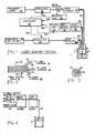
- Figure 1 is a block diagram of a laser system utilizing the invention;
- Figure 2 is a schematic longitudinal section of the fiber optic cable of the system of Fig. 1;
- Figure 3 is a cross-sectional view of said cable along the lines III-III of Fig. 2;
- Figure 4 is a block diagram of a portion of the laser system of Figure 1 utilizing a single optical fiber; and
- Figure 5 is a block diagram of a portion of the laser system of Figure 1 utilizing two optical fibers.
- The invention will be described utilizing the example of the destruction of an
atheromatous plaque 4 from theartery 6 of Fig. 1. Initially, the patient is administered a dose of a dye to enhance the contrast between the treatment site (plaque) and the healthy surrounding tissue. A typical dye is a tetracycline which has the property of fluorescing when radiated with an ultraviolet light. This dye has a special property of accumulating within the plaque relative to normal healthy tissue. Therefore, a predetermined time after the administration of the dye, thefiberoptic cable 8 is inserted into the artery with the distal end thereof opposite the treatment site. Theoptical cable 8 in a first embodiment (see also Figs. 2 and 3) includes a centraloptical fiber 8a coupled to the output oflight coupler 26, an annular array ofoptical fibers 8b surrounding thecentral fiber 8a connected to the input oflight coupler 28, and an outer annular array of cables offibers 8c is coupled to the output oflight coupler 16.Light coupler 26, of conventional design, receives light from thediagnostic light source 22 via theoptical modulator 24.Diagnostic light source 22 for the present example would be a source of ultraviolet light. If other dyes were used, then appropriate light sources for those dyes would be selected. The light indicated by a single arrowhead line feeds the input ofmodulator 24 whose output is fed to the input ofcoupler 26. Themodulator 24 can be of a conventional opto-accoustic modulator or an electromechanical shutter which passes or blocks the light in response to an electrical signal from controller 32 (note all electrical signal lines show double arrowheads). Thus, the presence or absence of a signal online 32a from thecontroller 32 can close or open the light path betweendiagnostic light source 22 andlight coupler 26. - The proximal end of
array 8b feeds light into thelight coupler 28 whose output is fed into thewavelength selector 34 which selects light corresponding to the predetermined characteristic wavelength to be detected. In turn, the selected light feeds detector-amplifier 30 whose output is fed viasignal lead 32b to thecontroller 32. The detector-amplifier 30 can be the combination of, for example, a photodiode which drives a transistor amplifier, a photomultiplier, or in and of itself can be a phototransistor. Thus, whenever light is received fromarray 8b, a signal will be transmitted tocontroller 32. The detector/amplifier 30 is controlled by signals online 32e fromcontroller 32. Treatment laser 10 will transmit light tomodulator 12 which is controlled by signals online 32c fromcontroller 32. The controlled light frommodulator 12 is fed to aconventional beam splitter 14 with a portion of light being deflected to detector/amplifier 20 and the remaining light passing to the input oflight coupler 16. The output oflight coupler 16 is fed to the proximal end ofoptical fiber array 8c.Beam splitter 14 also feeds part of the beam to detector/amplifier 20 which in turn feeds a signal online 32d tocontroller 32 which provides feedback sensing of the laser output to ensure constancy of the amplitude of the laser output over time.- In operation, after the dye has been inserted and the
cable 8 is in place, the diagnosticlight source 22 passes light viamodulator 24,coupler 26 andarray 8a to thetreatment site 4. The plaque in the treatment site will fluoresce and the fluorescence will be picked up by thearray 8b and fed to thelight coupler 28 and, thence, to thewavelength selector 34. The output from thewavelength selector 34, corresponding to the characteristic fluorescent emission of tetracycline, is fed to the detector/amplifier 30 which in response will emit a signal online 32b tocontroller 32. Thecontroller 32 in response thereto will send a signal online 32c to open the modulator 12 to emit laser energy of a predetermined power and wavelength for a set time interval. Accordingly, a pulse of light fromtreatment laser 10 will be fed via the beam splitter,light coupler 16 and thearray 8c to thetreatment area 4. Because light reflected from the treatment area can be very great during the time of the laser pulse,controller 32 vialine 32e feeds a signal to detector/amplifier 30 to turn off the detector for a predetermined time interval. This signal can also be fed tomodulator 24 to prevent the radiation of ultraviolet light during the laser pulse.Controller 32 then switches signals onlines detector 30 will send a signal tocontroller 32 which, again, switches the signals on thelines controller 32 and no further laser pulse is generated. In this way, using the probe-and-fire technique of the invention, the possibility of destroying healthy tissue is minimized. Thecontroller 32 in its simplest form can dispense with the use of detector/amplifier 20 and can merely be a monostable device which is momentarily triggered on a pulse fromline 32b and then reverts to its rest state. The paraphase output of this device can be connected via appropriate amplifiers tolines - To facilitate the positioning of the laser catheter within narrow tortuous pathways a single flexible optical fiber 8' (or small diameter bundle) is used (see Fig.4) instead of the
multibundle cable 8 of Fig. 1. More particularly, thelight couplers bundles treatment site 4 is fed from multiple-wavelength coupler MWLC via the common transmit-receive path into the port of multiple-wavelength beam splitter MWBS. This light is emitted therefrom to wavelength fitter 34 via a further path having an angle different from the two given incident path angles. Because of the nature of the multiple-wavelength beam splitter MWBS it may be possible to delete fitter 34 and feed detector/amplifier 30 directly from the beam splitter. - The so-modified system operates in the same manner as the system of Fig. 1. In Fig. 5 the fiber optical configuration is modified to a dual fiber configuration. This configuration may put less demands on the multiple-wavelength beam splitter MWBS and may permit more diagnostic light to reach the
treatment site 4. In this embodiment a single fiber orbundle 8a' is connected to light coupler 26(Fig 1). Thefiber 8" or narrow diameter cable is connected to multiple-wavelength light coupler MWFC which is optically-coupled via a common transmit-receive path to the ports of the multiple-wavelength beam splitter MWBS. Laser light is received along a given incident angle path from beam splitter 14 (Fig. 1) and fluorescent light from coupler MWFC is fed from multiple-wavelength beam splitter MWBS via an output optical path having a different angle to wavelength selector 34 (Fig. 1). As with the embodiment of Fig. 4 fitter 34 may be omitted. - Operation of the system utilizing the embodiment of Fig. 5 is the same as the other embodiments.
- In addition to tetracycline it has been found that the dye Nile Red (9-di-ethylamino-5h-benzo(α) phenoxazine-5-one) shows excellent results with plaque.
- While only a limited number of embodiments of the invention has been shown and described in detail, there will now be obvious to those skilled in the art many modifications and variations satisfying many or all of the objects and features of the invention without departing from the spirit thereof. For example, while only the treatment of plaque has been described the invention can be used as a treatment of other diseases such as tumors (cancer), stones in urinary tract and gall bladder as well as prostate obstructions. In addition, depending on the nature of the treatment site, the appropriate dye is selected to enhance the contrast between normal tissue and malignant tissue. When the treatment site is a tumor, one can successfully use hematoporphyrin or its derivatives. In some cases, inherent differences in optical properties between the treatment site and the surrounding healthy tissue may eliminate the need for the dye. Again, depending on the treatment site and the dyes involved, the diagnostic light can be ultraviolet, infra red, white light, etc. Furthermore, again depending on the treatment site, the laser source can take many forms such as argon, Nd-yag, carbon dioxide, tunable dye, and excimer lasers with pulse or continuous output. The choice of the diagnostic light source is predicated on the optical characteristics of the dye and/or the treatment site. However, the choice of the coherent light source for the treatment laser does not have to match the absorption peak of the dye. The treatment laser can be any wavelength that destroys the diseased treatment site. Normally, there is a risk that this light will also destroy healthy tissue. However, the possibility does not exist since once the diseased treatment site is removed, the means for triggering the laser pulse is also removed.
- The fiberoptic cable can be coupled with catheter designs which include, but are not limited to, such features as endoscopy, balloon devices, steerable guiding systems, multiple lumens for infusion and suctioning, ultrasonic guidance, monitoring or ablation, pressure and temperature monitoring and catheter centering devices.
- Further embodiments of the invention will be described with reference to Figures 6 to 8.
- The "Probe and Fire" laser system of Figure 6 utilizes the optical characteristic properties of the treatment area as the input to a control system which controls the firing of the treatment laser.
- The "Probe and Fire" laser system consists of the following major components - (1) a diagnostic light source to illuminate the treatment area, (2) various light delivery fibers and optics, (3) optical multichannel analyzer and spectrometer to capture the emission spectrum of the treatment area, (4) a treatment laser and a (5) computer control system capable of performing signal processing of the emission spectrum from the treatment area, controlling the optical characteristics of the light diagnostic light source and treatment laser such as wavelength, pulse width, amplitude and firing duration.
- The instrument is operated in the following manner. The
controller 32 first actives the diagnosticlight source 22 and thetreatment laser 10 in a "ready" mode. The illumination duration intensity and wavelength are controlled bymodulator 24. The diagnostic light is reflected bybeam splitter 54 which has high reflectivity at diagnostic light wavelengths and transmits light at other wavelengths.Beam splitter 52 is transparent to the diagnostic light which is then focused on theoptical fiber 8 through theoptical fiber coupler 42. The optical fiber is mated with a catheter 9 - through acatheter coupler 50. The treatment area is illuminated by the diagnostic light and its emission spectrum is collected byoptical fiber 9. The light retraces the optical path of the diagnostic light.Beam splitter 52 is transparent to the characteristic light and the same is true forbeam splitter 54. The characteristic spectral light goes throughBeam Splitter 54 and is coupled into optical fiber58 by theoptical fiber coupler 44. The light emerging from optical fiber58 is focused into the entrance slit of a spectrometer55 by acoupling optic 46. The full emission spectrum is recorded by an opticalmultichannel analyser 56. The spectrum is then processed by the computer in thecontroller 32. Certain characteristics (eg: wavelength) of the spectrum are identified as a means to discriminate the desired treatment area and to collect diagnostic information from the treatment area. After the desired treatment area is identified and the condition of the area is known the command is given by the controller to fire thetreatment laser 10 at a given wavelength, intensity, and duration. Intensity and wavelength are controlled by themodulator 12.Beam splitter 14 diverges a small fraction of the light from the treatment laser intodetector amplifier 20 which is fed back to the controller as a means to monitor the laser output. The treatment laser light is reflected into the fiber optics delivery system bybeam splitter 52 which has high reflectivity at treatment laser wavelength and transmits light at other wavelengths. The treatment laser light is coupled intooptical fiber 8 byoptical coupler 42 and the light is delivered into the catheter bycoupler 50. It reaches thetreatment area 4 throughcatheter 9. - After the firing procedure of the treatment laser is completed, the treatment area is examined by the diagnostic light again. The emission spectrum from the treated area will determine whether repeated firing is required or not. Referring to Figure 7. A more detailed embodiment of the system is for variable wavelength application. For multiwavelength applications, the
beam splitters polarization beam splitters 54b, 52b which reflect light with polarization perpendicular to the plan of incidence and transmits light parallel to the plan of incidence. The treatment laser will be "P" polarized with respect to thebeam splitter 52 and the diagnostic light source will be "S" polarized with respect tobeam splitter 54. The diagnostic light will pass through bothbeam splitters 54b and 52b and be focused onoptical fiber 8 byoptical coupler 42. - The emission spectrum returning from the treatment area is usually randomly polarized, half of it goes through beam splitter 52b and half of the remaining is reflected into the spectrum analyzer module which is composed of a spectrometer, optical multichannel analyzer and computer.
- The diagnostic light coming out of the light source and modulator is polarized and with its polarization vector perpendicular to the plane of incidence. It passes through the
polarizing beam splitter 54b and polarizing beam splitter 52b and is coupled intooptical fiber 8 byfiber optic coupler 42. The light emitted by the treatment area after being excited by the diagnostc light, is transmitted back to the instrument byoptic fiber 9,catheter coupler 50 andoptic fiber 8 as in figure 1, andcoupler 42 as shown in figure 6. It then transmitts through polarization beam splitter 52b partially and is reflected into thelight coupler 44 partially. - Both embodiments of the laser system instruments can be used, if desired for fluorescence detection only. The sensitivity of the instrument can thus be enhanced by removing the
beam splitter 52 which couples the treatment laser beam into the system when the system is used only as fluorescence detection device. - The arrangement of Figure 7 allows the use of a broader range of operating wavelengths for the diagnostic light and the treatment of light.
- Another embodiment is a dual channel laser surgical and fluorescent detection system. The diagnostic light and the treatment laser light are transmitted through two different fibers as is shown in figure 8. This allows diagnostic light of variable wavelength to be coupled into the fiber. The diagnostic light coming out of the
modulator 24 is coupled intooptic fiber 72 withfiber optic coupler 66. It illuminates thetreatment area 4. Light emitted by thetreatment area 4 is collected byoptic fiber 74 and directed into the optical spectrum analyser through thefiber optic coupler 64 andpolarizing beam splitter 62. After the signal processing procedure, if the treatment laser is given a command to fire, the treatment laser will give out polarized laser light with the polarization vector perpendicular to the incidence plane of the polarizing beam splitter and is reflected into the fiber optic coupler and it is then transmitted throughfiber 74 into the treatment area. To enhance the sensitivity of the system, the fiber tip of 72 can be a convex lens such that it focuses the treatment light at a distance away from the fiber exit surface. This system can also be efficiently used as a fluorescence detection system.
Claims (11)
- A surgical laser apparatus for operating on a treatment site comprising:
a fiber optical means (8) having a proximal end and a distal end positionable in operative proximity to the treatment site (4),
a treatment laser source (10) optically connected to the proximal end of said fiber optical means (8),
a diagnostic radiation source (22) connected to the proximal end of said fiber optical means (8) for irradiating the treatment site (4);
a responding radiation detector means (30) connected to the proximal end of said fiber optical means (8) characterised in that;
said radiation detector means (30) generates a control signal when detecting a particular radiation emitted or reflected, in use, by the part of said treatment site to be treated in response to being irradiated by said diagnostic radiation source (22); and
means (32) for controlling said treatment laser source to operate only when said radiation detector means (30) emits said control signal. - The apparatus as claimed in claim 1 characterised in that said fiber optical means comprises a multiple-wavelength beam splitter (MWBS), a fiber optical device (8') and a multiple-wavelength optical coupler (MWFC) optically coupling said multiple-wavelength beam splitter (MWBS) to said fiber optical device (8').
- The apparatus as claimed in claim 1 charcterised in that said fiber optical means (8) comprises first and second fiber optical devices (8",8a'), a multiple-wavelength beam splitter (MWBS) optically coupled to said treatment laser source (10) and to said responding radiation detector (30), a multiple-wavelength optical coupler (MWFC) optically coupling said diagnostic radiation source (22) to said second fiber optical device (8a').
- The apparatus as claimed in claim 3 characterised in that at least one of said fiber optical devices (8) is a single optical fiber (8).
- The apparatus as claimed in claim 3 characterised in that at least one of said fiber optical devices (8) is a bundle of optical fibers (8).
- The apparatus as claimed in claim 1 characterised in that said fiber optical means (8) is a fiber optical device having a central fiber (8a), optical diagnostic means with a proximal end coupled to said diagnostic radiation source (22), a receiving fiber optical array means (8b) annularly disposed about said diagnostic means with a proximal end coupled to said detector (30), and a treatment fiber optical array (8c) also annularly disposed about said diagnostic means with one end coupled to said treatment laser source (10).
- The apparatus as claimed in claim 1 characterised in that the radiation detector means is arranged to detect radiation of a particular wavelength or wavelengths only.
- The apparatus as claimed in any of claims 1 to 7 characterisd in that the radiation from the part to be treated is provided by fluorescence of the part to be treated emitted in response to receipt of diagnostic radiation from the diagnostic radiation source (22).
- The apparatus as claimed in any of claims 2 to 8 characterised in that the controller means (32) includes means to control said treatment laser source (10) to provide a series of bursts of laser radiation.
- The apparatus as claimed in any of claims 1 to 9 charcterised in that the distal end of the fiber optical means (8) is of a form suitable for insertion into the arteries of a patient.
- A surgical laser apparatus for operating on a treatment site comprising:
a fiber optical means (8) having a proximal end and a distal end positionable in operative proximity to the treatment site (4);
a treatment laser source (10) optically connected to the proximal end of said fiber optical means (8);
a diagnostic radiation source (22) connected to the proximal end of said fiber optical means (8) for irradiating the treatment site (4);
a responding radiation detector means (30) connected to the proximal end of said fiber optical means (8);
whereby in use, the part of said treatment site to be treated provides a different response to the receipt of radiation from said diagnostic radiation source to the remainder of the treatment site characterised in that;
said radiation detector means (30) is adapted to provide a control signal when detecting said different response of said part of said treatment site to be treated; and
means (32) for controlling said treatment laser source (10) to operate only when said radiation detector means (30) emits said control signal.
Priority Applications (1)
| Application Number | Priority Date | Filing Date | Title |
|---|---|---|---|
| AT86301737TATE76275T1 (en) | 1985-03-11 | 1986-03-11 | SURGICAL LASER SYSTEM. |
Applications Claiming Priority (4)
| Application Number | Priority Date | Filing Date | Title |
|---|---|---|---|
| US710431 | 1985-03-11 | ||
| US06/710,431US4641650A (en) | 1985-03-11 | 1985-03-11 | Probe-and-fire lasers |
| US06/788,949US4682594A (en) | 1985-03-11 | 1985-10-18 | Probe-and-fire lasers |
| US788949 | 2010-05-27 |
Publications (3)
| Publication Number | Publication Date |
|---|---|
| EP0194856A2 EP0194856A2 (en) | 1986-09-17 |
| EP0194856A3 EP0194856A3 (en) | 1987-06-03 |
| EP0194856B1true EP0194856B1 (en) | 1992-05-20 |
Family
ID=27108447
Family Applications (1)
| Application Number | Title | Priority Date | Filing Date |
|---|---|---|---|
| EP86301737AExpiredEP0194856B1 (en) | 1985-03-11 | 1986-03-11 | Surgical laser system |
Country Status (4)
| Country | Link |
|---|---|
| US (1) | US4682594A (en) |
| EP (1) | EP0194856B1 (en) |
| CA (1) | CA1263711A (en) |
| DE (1) | DE3685349D1 (en) |
Families Citing this family (85)
| Publication number | Priority date | Publication date | Assignee | Title |
|---|---|---|---|---|
| US4627436A (en)* | 1984-03-01 | 1986-12-09 | Innoventions Biomedical Inc. | Angioplasty catheter and method for use thereof |
| US5989243A (en)* | 1984-12-07 | 1999-11-23 | Advanced Interventional Systems, Inc. | Excimer laser angioplasty system |
| US5188632A (en)* | 1984-12-07 | 1993-02-23 | Advanced Interventional Systems, Inc. | Guidance and delivery system for high-energy pulsed laser light |
| US5125404A (en)* | 1985-03-22 | 1992-06-30 | Massachusetts Institute Of Technology | Apparatus and method for obtaining spectrally resolved spatial images of tissue |
| US5106387A (en)* | 1985-03-22 | 1992-04-21 | Massachusetts Institute Of Technology | Method for spectroscopic diagnosis of tissue |
| US5034010A (en)* | 1985-03-22 | 1991-07-23 | Massachusetts Institute Of Technology | Optical shield for a laser catheter |
| CA1266888A (en)* | 1985-04-08 | 1990-03-20 | Martin Prince | Laser-induced ablation of atherosclerotic plaque |
| AU576428B2 (en)* | 1986-05-16 | 1988-08-25 | Gv Medical Inc. | Laser catheter feed back system |
| WO1988008279A1 (en)* | 1987-04-25 | 1988-11-03 | Kristian Hohla | Device for treating tissues with laser |
| US4832023A (en)* | 1987-06-03 | 1989-05-23 | Mcm Laboratories, Inc. | Method and apparatus for reducing blockage in body channels |
| DE3733489A1 (en)* | 1987-10-03 | 1989-04-20 | Telemit Electronic Gmbh | METHOD AND DEVICE FOR PROCESSING MATERIALS WITH THE AID OF A LASER |
| US4788975B1 (en)* | 1987-11-05 | 1999-03-02 | Trimedyne Inc | Control system and method for improved laser angioplasty |
| DE3800555A1 (en)* | 1988-01-12 | 1989-07-27 | Ulrich Dardenne Stiftung Ev | DEVICE FOR THE ABLATIVE PHOTODECOMPOSITION OF DENTAL RESIN SUBSTANCES BY MEANS OF A WAVELENGTH OF 193 NM ARGON / FLUORID EXCIMER LASERS AND AN APPLICATION DEVICE FOR THIS LASER LIGHTING DEVICE |
| WO1989011828A1 (en)* | 1988-06-04 | 1989-12-14 | Sumitomo Electric Industries, Ltd. | Laser-aided intravascular operation equipment |
| JPH01308544A (en)* | 1988-06-06 | 1989-12-13 | Sumitomo Electric Ind Ltd | Intrabody laser surgery device |
| CH676661A5 (en)* | 1988-06-16 | 1991-02-28 | Claude F Dr Rausis | |
| US5147349A (en)* | 1988-10-07 | 1992-09-15 | Spectra-Physics, Inc. | Diode laser device for photocoagulation of the retina |
| SE8900612D0 (en)* | 1989-02-22 | 1989-02-22 | Jonas Johansson | TISSUE CHARACTERIZATION USING A BLOOD-FREE FLUORESCENCE CRITERIA |
| US5012087A (en)* | 1989-04-13 | 1991-04-30 | General Electric Company | Fiber optic safety system |
| JP2798218B2 (en)* | 1990-01-08 | 1998-09-17 | 三菱重工業株式会社 | Laser welding monitoring equipment |
| DE9004934U1 (en)* | 1990-04-30 | 1991-08-29 | Rofin-Sinar Laser GmbH, 2000 Hamburg | Device for transmitting laser light |
| DE4017441A1 (en)* | 1990-05-30 | 1991-12-05 | Weimel Erich | LASER SYSTEM |
| US5312396A (en)* | 1990-09-06 | 1994-05-17 | Massachusetts Institute Of Technology | Pulsed laser system for the surgical removal of tissue |
| US6113587A (en) | 1990-09-24 | 2000-09-05 | Plc Medical Systems, Inc. | Handpiece for a medical laser system |
| US5275594A (en)* | 1990-11-09 | 1994-01-04 | C. R. Bard, Inc. | Angioplasty system having means for identification of atherosclerotic plaque |
| US5188111A (en)* | 1991-01-18 | 1993-02-23 | Catheter Research, Inc. | Device for seeking an area of interest within a body |
| DE4105060A1 (en)* | 1991-02-19 | 1992-08-20 | Med Laserzentrum Luebeck Gmbh | METHOD AND DEVICE FOR MONITORING THE MATERIAL PROCESSING BY MEANS OF PULSED LASER LIGHT |
| DE4114492C2 (en)* | 1991-05-03 | 1996-10-24 | Baasel Carl Lasertech | Method and device for material processing using a laser |
| US5571335A (en)* | 1991-12-12 | 1996-11-05 | Cold Jet, Inc. | Method for removal of surface coatings |
| US5194723A (en)* | 1991-12-24 | 1993-03-16 | Maxwell Laboratories, Inc. | Photoacoustic control of a pulsed light material removal process |
| US5281798A (en)* | 1991-12-24 | 1994-01-25 | Maxwell Laboratories, Inc. | Method and system for selective removal of material coating from a substrate using a flashlamp |
| US5204517A (en)* | 1991-12-24 | 1993-04-20 | Maxwell Laboratories, Inc. | Method and system for control of a material removal process using spectral emission discrimination |
| US5328517A (en)* | 1991-12-24 | 1994-07-12 | Mcdonnell Douglas Corporation | Method and system for removing a coating from a substrate using radiant energy and a particle stream |
| US5613509A (en)* | 1991-12-24 | 1997-03-25 | Maxwell Laboratories, Inc. | Method and apparatus for removing contaminants and coatings from a substrate using pulsed radiant energy and liquid carbon dioxide |
| US5782253A (en)* | 1991-12-24 | 1998-07-21 | Mcdonnell Douglas Corporation | System for removing a coating from a substrate |
| US5512123A (en)* | 1992-05-19 | 1996-04-30 | Maxwell Laboratories | Method for using pulsed optical energy to increase the bondability of a surface |
| US6690963B2 (en) | 1995-01-24 | 2004-02-10 | Biosense, Inc. | System for determining the location and orientation of an invasive medical instrument |
| DE19542955C2 (en)* | 1995-11-17 | 1999-02-18 | Schwind Gmbh & Co Kg Herbert | endoscope |
| AU5279898A (en) | 1996-03-29 | 1998-03-26 | Eclipse Surgical Technologies, Inc. | Minimally invasive method and apparatus for forming revascularization channels |
| US6022309A (en)* | 1996-04-24 | 2000-02-08 | The Regents Of The University Of California | Opto-acoustic thrombolysis |
| DE19734732A1 (en) | 1996-12-10 | 1998-06-18 | Wavelight Laser Technologie Gm | Arrangement for treating bodily substances |
| DE19702353C5 (en)* | 1997-01-23 | 2004-03-25 | Wavelight Laser Technologie Gmbh | Device for intraocular cataract surgery |
| US6056742A (en)* | 1997-02-03 | 2000-05-02 | Eclipse Surgical Technologies, Inc. | Revascularization with laser outputs |
| US5993443A (en)* | 1997-02-03 | 1999-11-30 | Eclipse Surgical Technologies, Inc. | Revascularization with heartbeat verification |
| US5998768A (en)* | 1997-08-07 | 1999-12-07 | Massachusetts Institute Of Technology | Active thermal control of surfaces by steering heating beam in response to sensed thermal radiation |
| US6538739B1 (en) | 1997-09-30 | 2003-03-25 | The Regents Of The University Of California | Bubble diagnostics |
| US6539839B1 (en) | 1997-10-07 | 2003-04-01 | The Regents Of The University Of California | Uniform temperature cooking surface |
| US6055451A (en)* | 1997-12-12 | 2000-04-25 | Spectrx, Inc. | Apparatus and method for determining tissue characteristics |
| DE19906769A1 (en)* | 1998-02-19 | 1999-12-16 | Leica Microsystems | Overload protection arrangement for preventing damage to optical components by excessive light power from a light source, esp. for protecting a glass fiber system for transferring laser light |
| US6822187B1 (en) | 1998-09-09 | 2004-11-23 | Gsi Lumonics Corporation | Robotically operated laser head |
| IL141864A0 (en) | 1998-09-11 | 2002-03-10 | Spectrx Inc | Multi-modal optical tissue diagnostic system |
| US6303411B1 (en) | 1999-05-03 | 2001-10-16 | Vortek Industries Ltd. | Spatially resolved temperature measurement and irradiance control |
| US6817998B2 (en)* | 1999-07-23 | 2004-11-16 | Lahaye Leon C. | Method and apparatus for monitoring laser surgery |
| US6168827B1 (en) | 1999-08-30 | 2001-01-02 | General Electric Company | Fiber coating method |
| US6726549B2 (en)* | 2000-09-08 | 2004-04-27 | Cold Jet, Inc. | Particle blast apparatus |
| WO2002102265A1 (en)* | 2001-06-18 | 2002-12-27 | Medizinische Hochschule Hannover | Device for treating the human or animal body |
| US7505811B2 (en) | 2001-11-19 | 2009-03-17 | Dune Medical Devices Ltd. | Method and apparatus for examining tissue for predefined target cells, particularly cancerous cells, and a probe useful in such method and apparatus |
| US20070255169A1 (en)* | 2001-11-19 | 2007-11-01 | Dune Medical Devices Ltd. | Clean margin assessment tool |
| US20060177852A1 (en)* | 2001-12-12 | 2006-08-10 | Do-Coop Technologies Ltd. | Solid-fluid composition |
| DE10297622B4 (en) | 2001-12-26 | 2018-06-14 | Mattson Technology Inc. | Temperature measurement and methods and systems for heat treatment |
| US8116845B2 (en) | 2005-08-04 | 2012-02-14 | Dune Medical Devices Ltd. | Tissue-characterization probe with effective sensor-to-tissue contact |
| US8032211B2 (en)* | 2002-01-04 | 2011-10-04 | Dune Medical Devices Ltd. | Probes, systems, and methods for examining tissue according to the dielectric properties thereof |
| US20080287750A1 (en)* | 2002-01-04 | 2008-11-20 | Dune Medical Devices Ltd. | Ergonomic probes |
| US20080154090A1 (en)* | 2005-01-04 | 2008-06-26 | Dune Medical Devices Ltd. | Endoscopic System for In-Vivo Procedures |
| US7809425B2 (en)* | 2003-07-24 | 2010-10-05 | Dune Medical Devices Ltd. | Method and apparatus for examining a substance, particularly tissue, to characterize its type |
| US8019411B2 (en)* | 2002-01-04 | 2011-09-13 | Dune Medical Devices Ltd. | Probes, systems, and methods for examining tissue according to the dielectric properties thereof |
| US8721565B2 (en)* | 2005-08-04 | 2014-05-13 | Dune Medical Devices Ltd. | Device for forming an effective sensor-to-tissue contact |
| US7720532B2 (en) | 2004-03-23 | 2010-05-18 | Dune Medical Ltd. | Clean margin assessment tool |
| WO2004057650A1 (en) | 2002-12-20 | 2004-07-08 | Mattson Technology Canada, Inc. | Methods and systems for supporting a workpiece and for heat-treating the workpiece |
| JP5630935B2 (en) | 2003-12-19 | 2014-11-26 | マトソン テクノロジー、インコーポレイテッド | Apparatus and apparatus for suppressing thermally induced motion of workpiece |
| US9750425B2 (en) | 2004-03-23 | 2017-09-05 | Dune Medical Devices Ltd. | Graphical user interfaces (GUI), methods and apparatus for data presentation |
| US7904145B2 (en) | 2004-03-23 | 2011-03-08 | Dune Medical Devices Ltd. | Clean margin assessment tool |
| US20060062732A1 (en)* | 2004-09-10 | 2006-03-23 | Yasumi Uchida | Medicine for detecting lipid components in vivo and vascular endoscope |
| ES2434851T3 (en)* | 2005-03-29 | 2013-12-17 | Dune Medical Devices Ltd. | Electromagnetic sensors for tissue characterization |
| JP5680829B2 (en)* | 2006-02-01 | 2015-03-04 | ザ ジェネラル ホスピタル コーポレイション | A device that irradiates a sample with multiple electromagnetic radiations |
| WO2008058397A1 (en) | 2006-11-15 | 2008-05-22 | Mattson Technology Canada, Inc. | Systems and methods for supporting a workpiece during heat-treating |
| US8147423B2 (en)* | 2007-03-01 | 2012-04-03 | Dune Medical Devices, Ltd. | Tissue-characterization system and method |
| US7869016B2 (en)* | 2007-05-17 | 2011-01-11 | Ams Research Corporation | Fiber damage detection and protection device |
| JP5718809B2 (en) | 2008-05-16 | 2015-05-13 | マトソン テクノロジー、インコーポレイテッド | Method and apparatus for preventing destruction of workpieces |
| US10064554B2 (en) | 2011-12-14 | 2018-09-04 | The Trustees Of The University Of Pennsylvania | Fiber optic flow and oxygenation monitoring using diffuse correlation and reflectance |
| US9833146B2 (en)* | 2012-04-17 | 2017-12-05 | Covidien Lp | Surgical system and method of use of the same |
| US9282985B2 (en)* | 2013-11-11 | 2016-03-15 | Gyrus Acmi, Inc. | Aiming beam detection for safe laser lithotripsy |
| US9254075B2 (en) | 2014-05-04 | 2016-02-09 | Gyrus Acmi, Inc. | Location of fragments during lithotripsy |
| US9259231B2 (en) | 2014-05-11 | 2016-02-16 | Gyrus Acmi, Inc. | Computer aided image-based enhanced intracorporeal lithotripsy |
| JP6842431B2 (en)* | 2015-06-10 | 2021-03-17 | ボストン サイエンティフィック サイムド,インコーポレイテッドBoston Scientific Scimed,Inc. | Detection of substances in the body by evaluating the photoluminescent response to excited radiation |
Family Cites Families (12)
| Publication number | Priority date | Publication date | Assignee | Title |
|---|---|---|---|---|
| US3975748A (en)* | 1970-05-22 | 1976-08-17 | The United States Of America As Represented By The Secretary Of The Air Force | Multispectral laser camera device |
| US4207874A (en)* | 1978-03-27 | 1980-06-17 | Choy Daniel S J | Laser tunnelling device |
| JPS5552750A (en)* | 1978-10-12 | 1980-04-17 | Mochida Pharm Co Ltd | Laser knife* which can be detected* of tumor portion |
| USRE31815E (en)* | 1979-08-20 | 1985-01-29 | Philips Medical Systems, Inc. | Method and apparatus for detecting the presence of caries in teeth using visible luminescence |
| US4336809A (en)* | 1980-03-17 | 1982-06-29 | Burleigh Instruments, Inc. | Human and animal tissue photoradiation system and method |
| US4316467A (en)* | 1980-06-23 | 1982-02-23 | Lorenzo P. Maun | Control for laser hemangioma treatment system |
| US4438765A (en)* | 1981-06-04 | 1984-03-27 | Jack Wilinsky | Motion sensitive firable device |
| US4418688A (en)* | 1981-07-06 | 1983-12-06 | Laserscope, Inc. | Microcatheter having directable laser and expandable walls |
| JPS5821387A (en)* | 1981-07-29 | 1983-02-08 | Olympus Optical Co Ltd | Irradiator for laser |
| US4551829A (en)* | 1982-03-10 | 1985-11-05 | Harris Corporation | Wavelength division multiplexed fiber-optic cable system with non-unique terminal types |
| JPS5940869A (en)* | 1982-08-31 | 1984-03-06 | 工業技術院長 | Apparatus for treating cancer by using laser beam pulse |
| JPS5954488A (en)* | 1982-09-21 | 1984-03-29 | Nippon Sekigaisen Kogyo Kk | Laser irradiation device |
- 1985
- 1985-10-18USUS06/788,949patent/US4682594A/ennot_activeExpired - Lifetime
- 1986
- 1986-03-11DEDE8686301737Tpatent/DE3685349D1/ennot_activeExpired - Fee Related
- 1986-03-11EPEP86301737Apatent/EP0194856B1/ennot_activeExpired
- 1986-03-11CACA000503831Apatent/CA1263711A/ennot_activeExpired
Also Published As
| Publication number | Publication date |
|---|---|
| US4682594A (en) | 1987-07-28 |
| DE3685349D1 (en) | 1992-06-25 |
| EP0194856A2 (en) | 1986-09-17 |
| CA1263711A (en) | 1989-12-05 |
| EP0194856A3 (en) | 1987-06-03 |
Similar Documents
| Publication | Publication Date | Title |
|---|---|---|
| EP0194856B1 (en) | Surgical laser system | |
| US4641650A (en) | Probe-and-fire lasers | |
| US4785806A (en) | Laser ablation process and apparatus | |
| US4981138A (en) | Endoscopic fiberoptic fluorescence spectrometer | |
| US9950187B2 (en) | System and method for therapy and diagnosis comprising optical components for distribution of radiation | |
| JP2589674B2 (en) | Optical fiber equipment | |
| US20040092830A1 (en) | Catheter and method for diagnosis and treatment of diseased vessels | |
| EP1624796B1 (en) | System for therapy and diagnosis comprising in combination non-mechanical and mechanical distributors for distribution of radiation | |
| US20250064517A1 (en) | Fiber-optic medical treatment apparatus | |
| US20250064518A1 (en) | Fiber-optic medical treatment apparatus for treatment of a urinary track of a subject | |
| US20230210378A1 (en) | System and Method for Distributing Radiation for Diagnostics | |
| CN118785863A (en) | Disposable optical fiber apparatus | |
| WO2024223506A1 (en) | Medical laser apparatus | |
| JPH0489044A (en) | Laser therapeutic device |
Legal Events
| Date | Code | Title | Description |
|---|---|---|---|
| PUAI | Public reference made under article 153(3) epc to a published international application that has entered the european phase | Free format text:ORIGINAL CODE: 0009012 | |
| AK | Designated contracting states | Kind code of ref document:A2 Designated state(s):AT BE CH DE FR GB IT LI LU NL SE | |
| PUAL | Search report despatched | Free format text:ORIGINAL CODE: 0009013 | |
| AK | Designated contracting states | Kind code of ref document:A3 Designated state(s):AT BE CH DE FR GB IT LI LU NL SE | |
| 17P | Request for examination filed | Effective date:19871107 | |
| 17Q | First examination report despatched | Effective date:19890721 | |
| 18D | Application deemed to be withdrawn | Effective date:19900919 | |
| 18RA | Request filed for re-establishment of rights before grant | Effective date:19910425 | |
| RAP1 | Party data changed (applicant data changed or rights of an application transferred) | Owner name:ECLIPSE SURGICAL TECHNOLOGIES, INC. | |
| D18D | Application deemed to be withdrawn (deleted) | ||
| GRAA | (expected) grant | Free format text:ORIGINAL CODE: 0009210 | |
| AK | Designated contracting states | Kind code of ref document:B1 Designated state(s):AT BE CH DE FR GB IT LI LU NL SE | |
| REF | Corresponds to: | Ref document number:76275 Country of ref document:AT Date of ref document:19920615 Kind code of ref document:T | |
| ITF | It: translation for a ep patent filed | ||
| REF | Corresponds to: | Ref document number:3685349 Country of ref document:DE Date of ref document:19920625 | |
| ET | Fr: translation filed | ||
| PLBE | No opposition filed within time limit | Free format text:ORIGINAL CODE: 0009261 | |
| STAA | Information on the status of an ep patent application or granted ep patent | Free format text:STATUS: NO OPPOSITION FILED WITHIN TIME LIMIT | |
| 26N | No opposition filed | ||
| EPTA | Lu: last paid annual fee | ||
| EAL | Se: european patent in force in sweden | Ref document number:86301737.2 | |
| PGFP | Annual fee paid to national office [announced via postgrant information from national office to epo] | Ref country code:FR Payment date:19970213 Year of fee payment:12 | |
| PGFP | Annual fee paid to national office [announced via postgrant information from national office to epo] | Ref country code:NL Payment date:19970218 Year of fee payment:12 | |
| PGFP | Annual fee paid to national office [announced via postgrant information from national office to epo] | Ref country code:DE Payment date:19970225 Year of fee payment:12 | |
| PGFP | Annual fee paid to national office [announced via postgrant information from national office to epo] | Ref country code:GB Payment date:19970226 Year of fee payment:12 | |
| PGFP | Annual fee paid to national office [announced via postgrant information from national office to epo] | Ref country code:BE Payment date:19970317 Year of fee payment:12 | |
| PGFP | Annual fee paid to national office [announced via postgrant information from national office to epo] | Ref country code:SE Payment date:19980219 Year of fee payment:13 | |
| PGFP | Annual fee paid to national office [announced via postgrant information from national office to epo] | Ref country code:AT Payment date:19980223 Year of fee payment:13 | |
| PGFP | Annual fee paid to national office [announced via postgrant information from national office to epo] | Ref country code:LU Payment date:19980309 Year of fee payment:13 Ref country code:CH Payment date:19980309 Year of fee payment:13 | |
| PG25 | Lapsed in a contracting state [announced via postgrant information from national office to epo] | Ref country code:GB Free format text:LAPSE BECAUSE OF NON-PAYMENT OF DUE FEES Effective date:19980311 | |
| PG25 | Lapsed in a contracting state [announced via postgrant information from national office to epo] | Ref country code:FR Free format text:THE PATENT HAS BEEN ANNULLED BY A DECISION OF A NATIONAL AUTHORITY Effective date:19980331 Ref country code:BE Free format text:LAPSE BECAUSE OF NON-PAYMENT OF DUE FEES Effective date:19980331 | |
| BERE | Be: lapsed | Owner name:ECLIPSE SURGICAL TECHNOLOGIES INC. Effective date:19980331 | |
| PG25 | Lapsed in a contracting state [announced via postgrant information from national office to epo] | Ref country code:NL Free format text:LAPSE BECAUSE OF NON-PAYMENT OF DUE FEES Effective date:19981001 | |
| GBPC | Gb: european patent ceased through non-payment of renewal fee | Effective date:19980311 | |
| NLV4 | Nl: lapsed or anulled due to non-payment of the annual fee | Effective date:19981001 | |
| PG25 | Lapsed in a contracting state [announced via postgrant information from national office to epo] | Ref country code:DE Free format text:LAPSE BECAUSE OF NON-PAYMENT OF DUE FEES Effective date:19981201 | |
| REG | Reference to a national code | Ref country code:FR Ref legal event code:ST | |
| PG25 | Lapsed in a contracting state [announced via postgrant information from national office to epo] | Ref country code:LU Free format text:LAPSE BECAUSE OF NON-PAYMENT OF DUE FEES Effective date:19990311 Ref country code:AT Free format text:LAPSE BECAUSE OF NON-PAYMENT OF DUE FEES Effective date:19990311 | |
| PG25 | Lapsed in a contracting state [announced via postgrant information from national office to epo] | Ref country code:SE Free format text:LAPSE BECAUSE OF NON-PAYMENT OF DUE FEES Effective date:19990312 | |
| PG25 | Lapsed in a contracting state [announced via postgrant information from national office to epo] | Ref country code:LI Free format text:LAPSE BECAUSE OF NON-PAYMENT OF DUE FEES Effective date:19990331 Ref country code:CH Free format text:LAPSE BECAUSE OF NON-PAYMENT OF DUE FEES Effective date:19990331 | |
| EUG | Se: european patent has lapsed | Ref document number:86301737.2 | |
| REG | Reference to a national code | Ref country code:CH Ref legal event code:PL | |
| EUG | Se: european patent has lapsed | Ref document number:86301737.2 | |
| PG25 | Lapsed in a contracting state [announced via postgrant information from national office to epo] | Ref country code:IT Free format text:LAPSE BECAUSE OF NON-PAYMENT OF DUE FEES;WARNING: LAPSES OF ITALIAN PATENTS WITH EFFECTIVE DATE BEFORE 2007 MAY HAVE OCCURRED AT ANY TIME BEFORE 2007. THE CORRECT EFFECTIVE DATE MAY BE DIFFERENT FROM THE ONE RECORDED. Effective date:20050311 |