EP0193649A1 - Annealing basket - Google Patents
Annealing basketDownload PDFInfo
- Publication number
- EP0193649A1 EP0193649A1EP85115892AEP85115892AEP0193649A1EP 0193649 A1EP0193649 A1EP 0193649A1EP 85115892 AEP85115892 AEP 85115892AEP 85115892 AEP85115892 AEP 85115892AEP 0193649 A1EP0193649 A1EP 0193649A1
- Authority
- EP
- European Patent Office
- Prior art keywords
- frame
- pillars
- eyelet
- eyelets
- glow basket
- Prior art date
- Legal status (The legal status is an assumption and is not a legal conclusion. Google has not performed a legal analysis and makes no representation as to the accuracy of the status listed.)
- Granted
Links
- 238000000137annealingMethods0.000titledescription5
- 238000003466weldingMethods0.000claimsdescription14
- 230000008719thickeningEffects0.000claimsdescription8
- 230000000284resting effectEffects0.000claimsdescription2
- 238000004519manufacturing processMethods0.000description6
- 239000000463materialSubstances0.000description6
- 238000005266castingMethods0.000description2
- 238000010791quenchingMethods0.000description2
- 230000000171quenching effectEffects0.000description2
- 125000006850spacer groupChemical group0.000description2
- 230000008646thermal stressEffects0.000description2
- 238000010276constructionMethods0.000description1
- 239000007788liquidSubstances0.000description1
- 238000000034methodMethods0.000description1
- 230000007704transitionEffects0.000description1
Images

Classifications
- F—MECHANICAL ENGINEERING; LIGHTING; HEATING; WEAPONS; BLASTING
- F27—FURNACES; KILNS; OVENS; RETORTS
- F27D—DETAILS OR ACCESSORIES OF FURNACES, KILNS, OVENS OR RETORTS, IN SO FAR AS THEY ARE OF KINDS OCCURRING IN MORE THAN ONE KIND OF FURNACE
- F27D5/00—Supports, screens or the like for the charge within the furnace
- F27D5/0031—Treatment baskets for ceramic articles
- C—CHEMISTRY; METALLURGY
- C21—METALLURGY OF IRON
- C21D—MODIFYING THE PHYSICAL STRUCTURE OF FERROUS METALS; GENERAL DEVICES FOR HEAT TREATMENT OF FERROUS OR NON-FERROUS METALS OR ALLOYS; MAKING METAL MALLEABLE, e.g. BY DECARBURISATION OR TEMPERING
- C21D9/00—Heat treatment, e.g. annealing, hardening, quenching or tempering, adapted for particular articles; Furnaces therefor
- C21D9/0006—Details, accessories not peculiar to any of the following furnaces
- C21D9/0025—Supports; Baskets; Containers; Covers
Definitions
- the inventionrelates to a glow basket with a closed or rust-shaped bottom, which has upstanding pillars integrally formed on the edges, and with a frame resting on the pillars, which is captively attached to the pillars by means of flexible eyelet connections, each eyelet connection having a pin projecting through an eyelet has, the end of which carries a thickening not fitting through the eyelet.
- Annealing baskets for the transport of annealing material through an annealing furnace and also for quenching the annealing material in quenching liquidare exposed to large temperature fluctuations and local temperature differences, so that they suffer high thermal stresses. The greatest thermal stress occurs on the frame that forms the upper rim of the glow basket.
- the bottomis made together with the upstanding pillars molded onto it as a one-piece casting.
- the framewhich is made as a separate part, is inserted into grooves at the upper ends of the pillars.
- the frameis attached to the pillars with eyelets or frames that protrude downwards from the outside of the frame and overlap thickened heads of the pillars.
- eyelets or framesthat protrude downwards from the outside of the frame and overlap thickened heads of the pillars.
- the third web closing the eyeletis later welded on as the final link after the frame has been placed on the ends of the pillars. This welding of the closing links requires two welding points on each eyelet and the use of foreign material for the closing link. This results in a high amount of manual manufacturing work and manufacturing costs.
- the inventionhas for its object to improve a glow basket of the type mentioned with regard to simpler manufacturing options.
- the eyeletsare cast in one piece onto the pillars or the frame and are aligned horizontally and that the thickenings are welded to the vertically extending pin.
- the eyeletsare not completed by a closing member in a later manufacturing step, but they are completely molded onto this floor or frame when the floor or frame is poured.
- the vertical pinsare inserted into the horizontal eyelets.
- the lockingthen takes place by welding the thickened portions to the ends of the pins protruding through the eyelets. Only one welding process is required to lock each eyelet connection.
- the thickeningspreferably consist of welding points, each welding point being produced by applying welding material. Apart from the welding material, no additional foreign material is required.
- the welding pointscan be easily produced by placing a welding electrode on the pins, but care must be taken that the welding points are at a distance from the eyelet so that the eyelet is not pinched and the flexibility of the eyelet connection is maintained.
- the eyeletsare preferably molded onto the frame and the pillars have horizontal standing surfaces for the frame on their inner sides.
- the standing surfaceswhich are not limited to the inside of the glow basket by protruding parts, allow movements of the frame with respect to the floor or the pillars. It is also achieved that the inside of the frame is largely flush with the inner boundaries of the pillars, so that a wire mesh inserted in the glow basket is not bent at the transition between pillars and frame.
- the upper framecan be made in one piece, but expediently consists of separate frame strips. If the frame consists of separate strips, these frame strips can expand and move independently of one another. In addition, the frame strips are easier to manufacture in separate molds than a one-piece frame.
- the pillars at the corners of the flooreach protrude through two eyelets of the two adjacent frame strips and that the two eyelets are arranged at different heights. This results in a simple design of the corner connections in a multi-part frame.
- the glow basket according to the inventionnot only has the advantage of a simple construction, but it is also stackable and slidable on the furnace floor.
- the eyelet connectionsprovide the play required in all directions and the flexibility between the floor and frame.
- the glow basket shownhas a bottom 10 and an upper frame 11.
- the bottom 10consists of a one-piece part of a flat floor grating 12 made of crossing bars and vertical pillars 13 projecting at the edge of the floor grating, each of which merges into the bars of the floor grating.
- Each pillar 13has on its inside a horizontal contact surface 14 which is delimited on the outside by a protruding pin 15 and runs freely towards the inside of the glow basket, ie is not delimited by protruding parts.
- the upper frame 11is placed on the standing surfaces 14 of the pillars 13.
- This framelike the floor 10, is rectangular and it consists of the two longitudinal frame strips 16 and the two transverse frame strips 17. These frame strips 16 and 17 are separate castings.
- Each of the frame stripsconsists of an upright strip, on the outside of which numerous eyelets 18 project near the lower edge.
- the eyelets 18run horizontally, i.e. they have vertical openings.
- the rectangular eyelets 18are delimited on one side by the strip of the respective frame strip 16 and 17 and on the three other sides by the U-shaped eyelet webs.
- the height of each eyeletis about half the height of the frame strip.
- the transverse frame strips 17each have two molded handles 19.
- each frame bar 17stands on the horizontal standing surfaces 14 of the pillars 13, the inside of the pillars 13 being flush with the inside of the frame bar 16 and 17, respectively.
- the Hole 20 of the eyelet 18is oversized compared to the cross section of the pin 15 which forms the upper end of the pillar 13.
- the pin 15protrudes through the hole 20. Since the height of the pin 15 is approximately equal to the height of the frame bar 17, the top of the pin 15 is flush with the frame bar 17.
- a thickening 21 in the form of a weld spotis attached to the area of the pin 15 protruding from the eyelet 18.
- the thickening 21has a distance a from the top of the eyelet 18 in order to ensure the required flexibility of expansion.
- a spacer stripcan be placed on the top of the eyelet 18 in order to maintain the distance a. The spacer strip is then removed again.
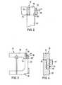
- Fig. 3shows a corner connection of the frame 11 of the glow basket.
- the standing surface 14 on the relevant pillar 13 'is arranged lower than in the other pillars.
- a downward extensionis provided, on which an eyelet 18 'is arranged, which rests on the base 14.
- the transverse frame strip 17 with the eyelet 18is placed on the eyelet 18 ', the pin 15 passing through both eyelets 18 and 18'.
- Fig. 4shows an embodiment in which the eyelets 18 are molded onto the pillars 13, while the pins 15, which pass vertically through the eyelets 18, project downward from the frame strip 17. At the end of the pin 15 protruding downward from the eyelet 18 is the subsequently applied thickening 21 in the form of a welding spot.
- the stand area 14is in this embodiment at the upper end of the pillar 13.
Landscapes
- Engineering & Computer Science (AREA)
- Chemical & Material Sciences (AREA)
- Mechanical Engineering (AREA)
- Organic Chemistry (AREA)
- General Engineering & Computer Science (AREA)
- Thermal Sciences (AREA)
- Materials Engineering (AREA)
- Metallurgy (AREA)
- Physics & Mathematics (AREA)
- Ceramic Engineering (AREA)
- Crystallography & Structural Chemistry (AREA)
- Heat Treatments In General, Especially Conveying And Cooling (AREA)
- Body Structure For Vehicles (AREA)
- Processing And Handling Of Plastics And Other Materials For Molding In General (AREA)
- Recrystallisation Techniques (AREA)
- Furnace Details (AREA)
- Manufacturing Of Tubular Articles Or Embedded Moulded Articles (AREA)
Abstract
Description
Translated fromGermanDie Erfindung betrifft einen Glühkorb mit geschlossenem oder rostförmigen Boden, der an den Rändern einstückig angeformte aufragende Pfeiler aufweist, und mit einem auf den Pfeilern ruhenden Rahmen, der an den Pfeilern über dehnungsbewegliche Ösenverbindungen unverlierbar befestigt ist, wobei jede ösenverbindung einen durch eine Öse hindurchragenden Zapfen aufweist, dessen Ende eine nicht durch die Öse hindurchpassende Verdickung trägt.The invention relates to a glow basket with a closed or rust-shaped bottom, which has upstanding pillars integrally formed on the edges, and with a frame resting on the pillars, which is captively attached to the pillars by means of flexible eyelet connections, each eyelet connection having a pin projecting through an eyelet has, the end of which carries a thickening not fitting through the eyelet.
Glühkörbe zum Transport von Glühgut durch einen Glühofen und auch zum Abschrecken des Glühgutes in Abschreckungsflüssigkeit sind großen Temperaturschwankungen und örtlichen Temperaturdifferenzen ausgesetzt, so daß sie große Wärmespannungen erleiden. Die größte thermische Beanspruchung tritt an dem Rahmen auf, der die obere Randeinfassung des Glühkorbes bildet.Annealing baskets for the transport of annealing material through an annealing furnace and also for quenching the annealing material in quenching liquid are exposed to large temperature fluctuations and local temperature differences, so that they suffer high thermal stresses. The greatest thermal stress occurs on the frame that forms the upper rim of the glow basket.
Bei einem bekannten Glühkorb der eingangs genannten Art (DE-OS 28 17 718) ist der Boden zusammen mit den ihm angeformten aufragenden Pfeilern als einstückiges Gußteil hergestellt. In Nuten an den oberen Enden der Pfeiler ist der als separates Teil hergestellte Rahmen eingesetzt. Die Befestigung des Rahmens an den Pfeilern erfolgt mit Ösen oder Rähmchen, die nach unten hin von der Außenseite des Rahmens abstehen und verdickte Köpfe der Pfeiler übergreifen. Bei der Herstellung des Rahmens werden für jede Öse nur zwei Stege gegossen. Der die Öse schließende dritte Steg wird als Schlußglied später angeschweißt, nachdem der Rahmen auf die Enden der Pfeiler aufgesetzt worden ist. Dieses Anschweißen der Schlußglieder erfordert an jeder Öse zwei Schweißstellen und zusätzlich den Einsatz von Fremdmaterial für das Schlußglied. Dies ergibt einen hohen Aufwand an manueller Fertigungsarbeit und Herstellungskosten.In a known glow basket of the type mentioned (DE-OS 28 17 718), the bottom is made together with the upstanding pillars molded onto it as a one-piece casting. The frame, which is made as a separate part, is inserted into grooves at the upper ends of the pillars. The frame is attached to the pillars with eyelets or frames that protrude downwards from the outside of the frame and overlap thickened heads of the pillars. In the manufacture of the frame, only two webs are cast for each eyelet. The third web closing the eyelet is later welded on as the final link after the frame has been placed on the ends of the pillars. This welding of the closing links requires two welding points on each eyelet and the use of foreign material for the closing link. This results in a high amount of manual manufacturing work and manufacturing costs.
Der Erfindung liegt die Aufgabe zugrunde, einen Glühkorb der eingangs genannten Art im Hinblick auf einfachere Fertigungsmöglichkeiten zu verbessern.The invention has for its object to improve a glow basket of the type mentioned with regard to simpler manufacturing options.
Die Lösung dieser Aufgabe besteht erfindungsgemäß darin, daß die Ösen den Pfeilern oder den Rahmen einstückig angegossen und horizontal ausgerichtet sind und daß die Verdickungen an den sich vertikal erstreckenden Zapfen angeschweißt sind.The solution to this problem is, according to the invention, that the eyelets are cast in one piece onto the pillars or the frame and are aligned horizontally and that the thickenings are welded to the vertically extending pin.
Bei dem erfindungsgemäßen Glühkorb werden die Ösen nicht in einem späteren Fertigungsschritt durch ein Schlußglied vervollständigt, sondern sie werden beim Gießen des Bodens oder des Rahmens diesem Boden oder Rahmen vollständig angeformt. Bei der Montage des Rahmens an den Enden der Pfeiler des Bodens werden die vertikalen Zapfen in die horizontalen Ösen eingesteckt.In the glow basket according to the invention, the eyelets are not completed by a closing member in a later manufacturing step, but they are completely molded onto this floor or frame when the floor or frame is poured. When mounting the frame on the ends of the pillars of the floor, the vertical pins are inserted into the horizontal eyelets.
Die Verriegelung erfolgt anschließend durch Anschweißen der Verdickungen an den durch die Ösen hindurchragenden Enden der Zapfen. Hierbei ist für die Verriegelung jeder ösenverbindung nur ein einziger Schweißvorgang erforderlich. Vorzugsweise bestehen die Verdickungen aus Schweißpunkten, wobei jeder Schweißpunkt durch Schweißmaterialauftrag erzeugt ist. Hierbei wird außer dem Schweißmaterial kein zusätzliches Fremdmaterial benötigt. Die Schweißpunkte können auf einfache Weise durch gezieltes Ansetzen einer Schweißelektrode an die Zapfen hergestellt werden, wobei jedoch darauf zu achten ist, daß die Schweißpunkte einen Abstand von der Öse haben, damit diese nicht eingeklemmt wird und die Dehnungsbeweglichkeit der ösenverbindung beibehalten wird.The locking then takes place by welding the thickened portions to the ends of the pins protruding through the eyelets. Only one welding process is required to lock each eyelet connection. The thickenings preferably consist of welding points, each welding point being produced by applying welding material. Apart from the welding material, no additional foreign material is required. The welding points can be easily produced by placing a welding electrode on the pins, but care must be taken that the welding points are at a distance from the eyelet so that the eyelet is not pinched and the flexibility of the eyelet connection is maintained.
Vorzugsweise sind die Ösen dem Rahmen angeformt und die Pfeiler weisen an ihren Innenseiten horizontale Standflächen für den Rahmen auf. Die Standflächen, die zum Innern des Glühkorbs nicht durch aufragende Teile begrenzt sind, erlauben Bewegungen des Rahmens in Bezug auf den Boden bzw. die Pfeiler. Außerdem wird erreicht, daß die Innenseite des Rahmens weitgehend bündig ist mit den inneren Begrenzungen der Pfeiler, so daß ein in den Glühkorb eingesetztes Drahtgitter am Übergang zwischen Pfeilern und Rahmen nicht verbogen wird.The eyelets are preferably molded onto the frame and the pillars have horizontal standing surfaces for the frame on their inner sides. The standing surfaces, which are not limited to the inside of the glow basket by protruding parts, allow movements of the frame with respect to the floor or the pillars. It is also achieved that the inside of the frame is largely flush with the inner boundaries of the pillars, so that a wire mesh inserted in the glow basket is not bent at the transition between pillars and frame.
Der obere Rahmen kann einstückig hergestellt werden, besteht jedoch zweckmäßigerweise aus separaten Rahmenleisten. Wenn der Rahmen aus separaten Leisten besteht, können sich diese Rahmenleisten unabhängig voneinander ausdehnen und bewegen. Außerdem lassen sich die Rahmenleisten in separaten Gießformen einfacher herstellen als ein einstückiger Rahmen.The upper frame can be made in one piece, but expediently consists of separate frame strips. If the frame consists of separate strips, these frame strips can expand and move independently of one another. In addition, the frame strips are easier to manufacture in separate molds than a one-piece frame.
Gemäß einer bevorzugten Weiterbildung der Erfindung ist vorgesehen, daß die Pfeiler an den Ecken des Bodens jeweils durch zwei ösen der beiden angrenzenden Rahmenleisten hindurchragen und daß die beiden ösen in unterschiedlichen Höhen angeordnet sind. Hierdurch ergibt sich bei einem mehrteiligen Rahmen eine einfache Gestaltung der Eckverbindungen.According to a preferred development of the invention, it is provided that the pillars at the corners of the floor each protrude through two eyelets of the two adjacent frame strips and that the two eyelets are arranged at different heights. This results in a simple design of the corner connections in a multi-part frame.
Der erfindungsgemäße Glühkorb hat nicht nur den Vorteil eines einfachen konstruktiven Aufbaus, sondern er ist auch stapelbar und auf dem Ofenboden verschiebbar. Die ösenverbindungungen liefern das in allen Richtungen erforderliche Spiel bzw. die Dehnungsbeweglichkeit zwischen Boden und Rahmen.The glow basket according to the invention not only has the advantage of a simple construction, but it is also stackable and slidable on the furnace floor. The eyelet connections provide the play required in all directions and the flexibility between the floor and frame.
Im folgenden werden unter Bezugnahme auf die Zeichnungen Ausführungsbeispiele der Erfindung näher erläutert.Exemplary embodiments of the invention are explained in more detail below with reference to the drawings.
Es zeigen:
- Fig. 1 eine perspektivische Ansicht eines Bodens mit dem darauf zu befestigenden oberen Rahmen, der aus einzelnen Rahmenleisten besteht,
- Fig. 2 einen Schnitt durch eine ösenverbindung bei dem Glühkorb nach Fig. 1,
- Fig. 3 eine Ansicht einer Eckverbindung bei dem Glühkorb nach Fig. 1 und
- Fig. 4 einen Schnitt durch eine andere Ausführungsform der ösenverbindung.
- 1 is a perspective view of a floor with the upper frame to be attached, which consists of individual frame strips,
- 2 shows a section through an eyelet connection in the glow basket according to FIG. 1,
- Fig. 3 is a view of a corner connection in the glow basket according to Fig. 1 and
- Fig. 4 shows a section through another embodiment of the eyelet connection.
Der dargestellte Glühkorb weist einen Boden 10 und einen oberen Rahmen 11 auf. Der Boden 10 besteht aus einem einstückigen Teil aus einem ebenen Bodenrost 12 aus einander kreuzenden Gitterstäben und am Rand des Bodenrostes aufragenden senkrechten Pfeilern 13, die jeweils in die Gitterstäbe des Bodenrostes übergehen. Jeder Pfeiler 13 weist an seiner Innenseite eine horizontale Aufstandfläche 14 auf, die nach außen durch einen aufragenden Zapfen 15 begrenzt ist und zum Innern des Glühkorbs hin frei ausläuft, d.h. nicht durch aufragende Teile begrenzt ist.The glow basket shown has a
Auf die Standflächen 14 der Pfeiler 13 wird der obere Rahmen 11 gestellt. Dieser Rahmen ist, ebenso wie der Boden 10, rechteckig und er besteht aus den beiden längslaufenden Rahmenleisten 16 und den beiden querlaufenden Rahmenleisten 17. Diese Rahmenleisten 16 und 17 sind separate Gußteile. Jede der Rahmenleisten besteht aus einem hochkant stehenden Streifen, an dem außen in der Nähe der Unterkante zahlreiche Ösen 18 abstehen. Die Ösen 18 verlaufen horizontal, d.h. sie haben vertikale Durchtrittsöffnungen. Die rechteckigen ösen 18 sind an einer Seite durch den Streifen der jeweiligen Rahmenleiste 16 bzw. 17 begrenzt und an den drei anderen Seiten durch die U-förmig angeordneten ösenstege. Die Höhe einer jeden öse beträgt etwa die Hälfte der Höhe des Streifens der Rahmenleiste.The
Die querlaufenden Rahmenleisten 17 haben jeweils zwei angeformte Handgriffe 19.The
Wie Fig. 2 zeigt, steht jede Rahmenleiste 17 mit ihrer Unterseite auf den horizontalen Standflächen 14 der Pfeiler 13, wobei die Innenseiten der Pfeiler 13 mit der Innenseite der Rahmenleiste 16 bzw. 17 fluchten. Dies bedeutet, daß die Stärke der Rahmenleiste 17 annähernd der Breite der Standfläche 14 entspricht. Das Loch 20 der Öse 18 hat Übermaß gegenüber dem Querschnitt des Zapfens 15, der das obere Ende des Pfeilers 13 bildet. Der Zapfen 15 ragt durch das Loch 20 hindurch. Da die Höhe des Zapfens 15 etwa gleich der Höhe der Rahmenleiste 17 ist, schließt die Oberseite des Zapfens 15 bündig mit der Rahmenleiste 17 ab.As shown in FIG. 2, the underside of each
Zur Verhinderung des Entfernens der Rahmensleiste 17 von dem Pfeiler 13 ist an dem aus der öse 18 herausragenden Bereich des Zapfens 15 eine Verdickung 21 in Form eines Schweißpunktes angebracht. Die Verdickung 21 hat einen Abstand a von der Oberseite der öse 18, um die erforderliche Dehnungsbeweglichkeit sicherzustellen. Bei der Erzeugung des Schweißpunktes 21 kann ein Abstandsstreifen auf die Oberseite der öse 18 gelegt werden, um den Abstand a einzuhalten. Der Abstandsstreifen wird anschließend wieder entfernt.To prevent removal of the
Fig. 3 zeigt eine Eckverbindung des Rahmens 11 des Glühkorbs. An dem betreffenden Pfeiler 13' ist die Standfläche 14 tiefer angeordnet als bei den übrigen Pfeilern. An dem Ende der Rahmenleiste 16 ist eine nach unten gezogene Verlängerung vorgesehen, an der eine Öse 18' angeordnet ist, welche auf der Standfläche 14 aufliegt. Auf die öse 18' ist die querlaufende Rahmenleiste 17 mit der Öse 18 aufgesetzt, wobei der Zapfen 15 durch beide Ösen 18 und 18' hindurchgeht.Fig. 3 shows a corner connection of the
Fig. 4 zeigt ein Ausführungsbeispiel, bei dem die Ösen 18 den Pfeilern 13 angeformt sind, während die Zapfen 15, die vertikal durch die ösen 18 hindurchgehen, von der Rahmenleiste 17 nach unten abstehen. An dem aus der Öse 18 nach unten herausragenden Ende des Zapfens 15 befindet sich die nachträglich angebrachte Verdickung 21 in Form eines Schweißpunktes. Die Standfläche 14 befindet sich bei diesem Ausführungsbeispiel am oberen Ende des Pfeilers 13.Fig. 4 shows an embodiment in which the
Claims (5)
Translated fromGermandadurch gekennzeichnet ,
daß die Ösen (18) den Pfeilern (13) oder dem Rahmen (11) einstückig angegossen und horizontal ausgerichtet sind und daß die Verdickungen (21) an den sich vertikal erstreckenden Zapfen (15) angeschweißt sind.1. Glow basket with a closed or rust-shaped base, which has upstanding pillars integrally formed on the edges, and with a frame resting on the pillars, which is captively attached to the pillars by means of flexible eyelet connections, each eyelet connection having a pin projecting through an eyelet the end of which carries a thickening that does not pass through the eyelet,
characterized ,
that the eyelets (18) are cast onto the pillars (13) or the frame (11) in one piece and are aligned horizontally and that the thickened portions (21) are welded to the vertically extending pin (15).
Priority Applications (1)
| Application Number | Priority Date | Filing Date | Title |
|---|---|---|---|
| AT85115892TATE34185T1 (en) | 1985-03-02 | 1985-12-13 | GLOW BASKET. |
Applications Claiming Priority (2)
| Application Number | Priority Date | Filing Date | Title |
|---|---|---|---|
| DE3507439 | 1985-03-02 | ||
| DE19853507439DE3507439A1 (en) | 1985-03-02 | 1985-03-02 | GLOW BASKET |
Publications (2)
| Publication Number | Publication Date |
|---|---|
| EP0193649A1true EP0193649A1 (en) | 1986-09-10 |
| EP0193649B1 EP0193649B1 (en) | 1988-05-11 |
Family
ID=6264030
Family Applications (1)
| Application Number | Title | Priority Date | Filing Date |
|---|---|---|---|
| EP85115892AExpiredEP0193649B1 (en) | 1985-03-02 | 1985-12-13 | Annealing basket |
Country Status (4)
| Country | Link |
|---|---|
| US (1) | US4669978A (en) |
| EP (1) | EP0193649B1 (en) |
| AT (1) | ATE34185T1 (en) |
| DE (2) | DE3507439A1 (en) |
Cited By (2)
| Publication number | Priority date | Publication date | Assignee | Title |
|---|---|---|---|---|
| DE102007013177A1 (en)* | 2007-03-20 | 2008-09-25 | Hein, Lehmann Trenn- und Fördertechnik GmbH | Annealing basket for annealing metallic workpieces in an annealing furnace comprises supporting profiles extending in the transport direction, connected to a frame and inserted into a table construction |
| DE102008020040A1 (en)* | 2007-10-22 | 2009-04-23 | Otto Junker Gmbh | Furnace system i.e. roller hearth furnace system, for convective thermal treatment of copper flat coil, has radial ventilator arranged at blowing out side of heating unit in U-shaped flow channel system surrounding channel cross-section |
Families Citing this family (10)
| Publication number | Priority date | Publication date | Assignee | Title |
|---|---|---|---|---|
| US5310687A (en)* | 1984-10-31 | 1994-05-10 | Igen, Inc. | Luminescent metal chelate labels and means for detection |
| US5112974A (en)* | 1985-01-18 | 1992-05-12 | The Trustees Of Columbia University In The City Of New York | Mixed ligand complexes and uses thereof as binding agents to DNA |
| DE3507439A1 (en) | 1985-03-02 | 1986-09-04 | Rudolf 5000 Köln Klefisch | GLOW BASKET |
| US5752821A (en)* | 1996-07-02 | 1998-05-19 | Kia Motors Corporation | Tray for heat treatment furnace |
| EP0997541A1 (en)* | 1998-10-26 | 2000-05-03 | ALUMINIUM RHEINFELDEN GmbH | Heat treating box for annealing and degreasing pieces made of aluminium |
| EP1055007A1 (en)* | 1998-12-14 | 2000-11-29 | Koninklijke Philips Electronics N.V. | Carrier substrate |
| DE19957906A1 (en)* | 1999-12-01 | 2001-06-28 | Schunk Kohlenstofftechnik Gmbh | Method for producing a fiber composite component and device for producing one |
| US20040110301A1 (en)* | 2000-11-17 | 2004-06-10 | Neilson Andy C | Apparatus and methods for measuring reaction byproducts |
| WO2002061858A2 (en)* | 2000-11-17 | 2002-08-08 | Thermogenic Imaging, Inc. | Apparatus and methods for infrared calorimetric measurements |
| US20020132360A1 (en)* | 2000-11-17 | 2002-09-19 | Flir Systems Boston, Inc. | Apparatus and methods for infrared calorimetric measurements |
Citations (4)
| Publication number | Priority date | Publication date | Assignee | Title |
|---|---|---|---|---|
| DE1222522B (en)* | 1964-12-04 | 1966-08-11 | Pass & Co | Incinerator with stiffening elements for insertion in glow ovens |
| DE1900105A1 (en)* | 1969-01-02 | 1970-07-23 | Dr Konrad Buck | Drying plant for agricultural products or other substances |
| DE2817718A1 (en)* | 1978-04-22 | 1979-10-31 | Rudolf Klefisch | Metal annealing box - with cover secured in flange groove and u=shaped lugs around pillar heads |
| EP0015373A1 (en)* | 1979-02-08 | 1980-09-17 | Rudolf Klefisch | Annealing box |
Family Cites Families (9)
| Publication number | Priority date | Publication date | Assignee | Title |
|---|---|---|---|---|
| US2296380A (en)* | 1940-02-07 | 1942-09-22 | Davidson Avis Cole | Method of and apparatus for heat treating |
| US2453511A (en)* | 1946-05-08 | 1948-11-09 | Ohio Steel Foundry Co | Furnace tray basket |
| GB660124A (en)* | 1948-03-02 | 1951-10-31 | Rubery Owen & Co Ltd | A stillage or pallet |
| US3315835A (en)* | 1963-02-25 | 1967-04-25 | Reynolds Metals Co | Collapsible stacking crate |
| US3498597A (en)* | 1968-03-11 | 1970-03-03 | Rolock Inc | Annealing box |
| US4050604A (en)* | 1974-07-22 | 1977-09-27 | Flanders Robert D | Disassembleable, reusable container |
| US4463864A (en)* | 1982-09-30 | 1984-08-07 | Deere & Company | Basket for retaining parts during heat treatment |
| US4576300A (en)* | 1984-07-03 | 1986-03-18 | Allegheny Ludlum Steel Corporation | Reusable shipping container |
| DE3507439A1 (en) | 1985-03-02 | 1986-09-04 | Rudolf 5000 Köln Klefisch | GLOW BASKET |
- 1985
- 1985-03-02DEDE19853507439patent/DE3507439A1/ennot_activeCeased
- 1985-12-13ATAT85115892Tpatent/ATE34185T1/ennot_activeIP Right Cessation
- 1985-12-13EPEP85115892Apatent/EP0193649B1/ennot_activeExpired
- 1985-12-13DEDE8585115892Tpatent/DE3562629D1/ennot_activeExpired
- 1986
- 1986-02-24USUS06/832,329patent/US4669978A/ennot_activeExpired - Fee Related
Patent Citations (4)
| Publication number | Priority date | Publication date | Assignee | Title |
|---|---|---|---|---|
| DE1222522B (en)* | 1964-12-04 | 1966-08-11 | Pass & Co | Incinerator with stiffening elements for insertion in glow ovens |
| DE1900105A1 (en)* | 1969-01-02 | 1970-07-23 | Dr Konrad Buck | Drying plant for agricultural products or other substances |
| DE2817718A1 (en)* | 1978-04-22 | 1979-10-31 | Rudolf Klefisch | Metal annealing box - with cover secured in flange groove and u=shaped lugs around pillar heads |
| EP0015373A1 (en)* | 1979-02-08 | 1980-09-17 | Rudolf Klefisch | Annealing box |
Cited By (2)
| Publication number | Priority date | Publication date | Assignee | Title |
|---|---|---|---|---|
| DE102007013177A1 (en)* | 2007-03-20 | 2008-09-25 | Hein, Lehmann Trenn- und Fördertechnik GmbH | Annealing basket for annealing metallic workpieces in an annealing furnace comprises supporting profiles extending in the transport direction, connected to a frame and inserted into a table construction |
| DE102008020040A1 (en)* | 2007-10-22 | 2009-04-23 | Otto Junker Gmbh | Furnace system i.e. roller hearth furnace system, for convective thermal treatment of copper flat coil, has radial ventilator arranged at blowing out side of heating unit in U-shaped flow channel system surrounding channel cross-section |
Also Published As
| Publication number | Publication date |
|---|---|
| EP0193649B1 (en) | 1988-05-11 |
| DE3562629D1 (en) | 1988-06-16 |
| ATE34185T1 (en) | 1988-05-15 |
| US4669978A (en) | 1987-06-02 |
| DE3507439A1 (en) | 1986-09-04 |
Similar Documents
| Publication | Publication Date | Title |
|---|---|---|
| EP0193649B1 (en) | Annealing basket | |
| DE2613083A1 (en) | Pallet made from prefabricated plastic components - has two outside bridge profiles joined by four load panels (NL 28.9.77) | |
| EP0015373A1 (en) | Annealing box | |
| EP0130425B1 (en) | Form work for floors | |
| DE3223110C2 (en) | ||
| DE2847007C2 (en) | False ceiling | |
| EP0738661B1 (en) | Process and device for manufacturing of a pallet made of plastic material | |
| DE2311199C2 (en) | Device for locking platforms on scaffolding parts | |
| EP0630460B1 (en) | Basic frame for machines and the like | |
| DE2033724C3 (en) | Collapsible box | |
| EP0572946A2 (en) | Plastic pallet | |
| DE3826361C2 (en) | ||
| DE1554472B1 (en) | Device on shelves or the like. for easily detachable connection of a post with a support piece | |
| DE2817718C2 (en) | Annealing basket | |
| WO1992019778A1 (en) | Carrier for material to be annealed | |
| DE3512388A1 (en) | SHELF | |
| DE2343452A1 (en) | LATTICE GIRDER | |
| DE3317173C2 (en) | Annealing tray | |
| DE69100365T2 (en) | Extruded sheet and method of welding such a sheet. | |
| DE1927710C (en) | Adjustable storage rack | |
| DE19505193A1 (en) | Rectangular storage and transport container for tools and components For building industry | |
| AT251232B (en) | Frames, in particular support frames for movable containers | |
| DE3235394A1 (en) | Infant travel cot | |
| DE4036413C2 (en) | Crossbeam for containers and swap bodies | |
| DE2836794C2 (en) | Support grids for fuel elements of nuclear reactors |
Legal Events
| Date | Code | Title | Description |
|---|---|---|---|
| PUAI | Public reference made under article 153(3) epc to a published international application that has entered the european phase | Free format text:ORIGINAL CODE: 0009012 | |
| AK | Designated contracting states | Kind code of ref document:A1 Designated state(s):AT CH DE FR GB IT LI NL | |
| 17P | Request for examination filed | Effective date:19860729 | |
| 17Q | First examination report despatched | Effective date:19870804 | |
| GRAA | (expected) grant | Free format text:ORIGINAL CODE: 0009210 | |
| AK | Designated contracting states | Kind code of ref document:B1 Designated state(s):AT CH DE FR GB IT LI NL | |
| REF | Corresponds to: | Ref document number:34185 Country of ref document:AT Date of ref document:19880515 Kind code of ref document:T | |
| ITF | It: translation for a ep patent filed | ||
| GBT | Gb: translation of ep patent filed (gb section 77(6)(a)/1977) | ||
| REF | Corresponds to: | Ref document number:3562629 Country of ref document:DE Date of ref document:19880616 | |
| ET | Fr: translation filed | ||
| PLBE | No opposition filed within time limit | Free format text:ORIGINAL CODE: 0009261 | |
| STAA | Information on the status of an ep patent application or granted ep patent | Free format text:STATUS: NO OPPOSITION FILED WITHIN TIME LIMIT | |
| 26N | No opposition filed | ||
| PG25 | Lapsed in a contracting state [announced via postgrant information from national office to epo] | Ref country code:NL Effective date:19890701 | |
| NLV4 | Nl: lapsed or anulled due to non-payment of the annual fee | ||
| PGFP | Annual fee paid to national office [announced via postgrant information from national office to epo] | Ref country code:GB Payment date:19911112 Year of fee payment:7 | |
| PGFP | Annual fee paid to national office [announced via postgrant information from national office to epo] | Ref country code:FR Payment date:19911230 Year of fee payment:7 | |
| ITTA | It: last paid annual fee | ||
| PG25 | Lapsed in a contracting state [announced via postgrant information from national office to epo] | Ref country code:GB Effective date:19921213 | |
| PGFP | Annual fee paid to national office [announced via postgrant information from national office to epo] | Ref country code:DE Payment date:19921215 Year of fee payment:8 | |
| PGFP | Annual fee paid to national office [announced via postgrant information from national office to epo] | Ref country code:CH Payment date:19921229 Year of fee payment:8 | |
| PGFP | Annual fee paid to national office [announced via postgrant information from national office to epo] | Ref country code:AT Payment date:19921230 Year of fee payment:8 | |
| GBPC | Gb: european patent ceased through non-payment of renewal fee | Effective date:19921213 | |
| PG25 | Lapsed in a contracting state [announced via postgrant information from national office to epo] | Ref country code:FR Effective date:19930831 | |
| REG | Reference to a national code | Ref country code:FR Ref legal event code:ST | |
| PG25 | Lapsed in a contracting state [announced via postgrant information from national office to epo] | Ref country code:AT Effective date:19931213 | |
| PG25 | Lapsed in a contracting state [announced via postgrant information from national office to epo] | Ref country code:LI Effective date:19931231 Ref country code:CH Effective date:19931231 | |
| REG | Reference to a national code | Ref country code:CH Ref legal event code:PL | |
| PG25 | Lapsed in a contracting state [announced via postgrant information from national office to epo] | Ref country code:DE Effective date:19940901 |