EP0192797B1 - Coffee-making machine - Google Patents
Coffee-making machineDownload PDFInfo
- Publication number
- EP0192797B1 EP0192797B1EP85102303AEP85102303AEP0192797B1EP 0192797 B1EP0192797 B1EP 0192797B1EP 85102303 AEP85102303 AEP 85102303AEP 85102303 AEP85102303 AEP 85102303AEP 0192797 B1EP0192797 B1EP 0192797B1
- Authority
- EP
- European Patent Office
- Prior art keywords
- coffee
- piston
- feeder
- recess
- yoke
- Prior art date
- Legal status (The legal status is an assumption and is not a legal conclusion. Google has not performed a legal analysis and makes no representation as to the accuracy of the status listed.)
- Expired
Links
- 239000000843powderSubstances0.000claimsabstractdescription13
- XLYOFNOQVPJJNP-UHFFFAOYSA-NwaterSubstancesOXLYOFNOQVPJJNP-UHFFFAOYSA-N0.000claimsabstractdescription11
- 230000000630rising effectEffects0.000claims1
- 241000723377CoffeaSpecies0.000description73
- 238000002360preparation methodMethods0.000description12
- RZVAJINKPMORJF-UHFFFAOYSA-NAcetaminophenChemical compoundCC(=O)NC1=CC=C(O)C=C1RZVAJINKPMORJF-UHFFFAOYSA-N0.000description1
- 240000007154Coffea arabicaSpecies0.000description1
Images

Classifications
- A—HUMAN NECESSITIES
- A47—FURNITURE; DOMESTIC ARTICLES OR APPLIANCES; COFFEE MILLS; SPICE MILLS; SUCTION CLEANERS IN GENERAL
- A47J—KITCHEN EQUIPMENT; COFFEE MILLS; SPICE MILLS; APPARATUS FOR MAKING BEVERAGES
- A47J31/00—Apparatus for making beverages
- A47J31/24—Coffee-making apparatus in which hot water is passed through the filter under pressure, i.e. in which the coffee grounds are extracted under pressure
- A47J31/34—Coffee-making apparatus in which hot water is passed through the filter under pressure, i.e. in which the coffee grounds are extracted under pressure with hot water under liquid pressure
- A47J31/36—Coffee-making apparatus in which hot water is passed through the filter under pressure, i.e. in which the coffee grounds are extracted under pressure with hot water under liquid pressure with mechanical pressure-producing means
- A47J31/3604—Coffee-making apparatus in which hot water is passed through the filter under pressure, i.e. in which the coffee grounds are extracted under pressure with hot water under liquid pressure with mechanical pressure-producing means with a mechanism arranged to move the brewing chamber between loading, infusing and ejecting stations
- A47J31/3609—Loose coffee being employed
- A47J31/3614—Means to perform transfer from a loading position to an infusing position
Definitions
- the inventionrelates to a coffee machine, in which hot water is pressed through a portion of coffee powder lying in a cylindrical recess, with an annular coffee feeder that can be swiveled on one surface over the recess, open at the top and bottom, and can be lifted and lowered in the lowered operating position the swiveled-in coffee feeder into the recess, the hot water supplying upper piston and a liftable and lowerable one, which in the open end position of the upper piston extends to the upper edge of the recess and in the lowered operating position of the upper piston lying in the lower opening of the recess, the Upper piston is connected by means of a yoke to a drive rod which can be raised and lowered.
- a coffee machine of the type mentioned at the outsetis known from WO-AB 201 120.
- a major disadvantage of this coffee machineis that separate drives are provided for the upper piston, for the lower piston and for the coffee feeder. These drives take up a relatively large amount of space, require a relatively complicated control system and make the entire coffee machine more expensive.
- the aimis to create a coffee machine with which the aforementioned problems can be avoided.
- the coffee machine according to the inventionis characterized in that the coffee feeder is connected by means of the yoke to the drive rod which can be raised and lowered, and that there is a swivel rod between the yoke and the coffee feeder, which is rotatably mounted in the yoke by means of a helical drive and the Coffee feeder pivots from a first, swung-out end position into a second end position aligned with the upper piston and lower piston, and vice versa, while the upper piston moves from its open end position to the upper edge of the coffee feeder and vice versa.
- At least the coffee feeder and the upper pistoncan be driven at least mechanically or hydraulically by a single, common drive rod.
- Such a coffee machinecan take up less space, and the type of drive mentioned can also be realized at a significantly lower cost. It is advantageous if the lower piston is also driven by the same drive rod.
- the coffee machinehas a fixed vessel 1 to which a coffee preparation block 2 is attached.
- a bearing block 3is also fixed in place on the vessel 1 above a plate 4.
- a coffee line 5leads away from the coffee preparation block 2 and has, in a manner not shown, one or two coffee outlets from which the finished coffee is then discharged from the machine.
- the coffee preparation block 2is also provided with an obliquely downward sliding plate 6 for the used coffee powder cake.
- a cylindrical recess 9which opens out at the top on a surface 10 of the block 2 and has a bottom 11, from which an annular groove (not shown) communicates with the inside of the coffee line 5.
- a table top 12is also attached to the coffee preparation block 2.
- a drain pipe 13for hot water. All components 1 to 6 and 8 to 13 are therefore immobile.
- the coffee machinehas a coffee feeder 14, an upper piston 15 and a lower piston 16. There is also a drive rod 17, a yoke 18 and a swivel rod 19. These components 14 to 19 are movable and shown in different positions in FIGS. 1 and 2.
- the drive rod 17is guided in the bearing block 3 so that it can be lifted and lowered.
- a hole (not shown) in the coffee preparation block 2also serves to guide this drive rod 17.
- the drive rod 17is designed in the lower region as a toothed rack, that is to say it has a toothing 18 in which the drive pinion 7 engages.
- At the topis the drive rod 17 connected to the yoke 18.
- a stop 20is also attached.
- the drive rod 17can also be operated hydraulically instead of mechanically.
- the coffee feeder 14is provided with a through hole 21 and is freely rotatable on the cylindrical drive rod 17 between two positions. In one end position of the coffee feeder 14 according to FIG. 1, the through hole 21 is delimited at the bottom by the table top 12. In the other end position of the coffee feeder 14 according to FIG. 2, the through hole 21 is aligned with the upper piston 15, the lower piston 16 and thus also with the recess 9. The explained pivoting movement of the coffee feeder 14 takes place via a toothed segment 22 which meshes with a drive wheel 23.
- the pivot rod 19is rotatably supported in the bearing block 3 and in the yoke 18 at the bottom.
- the swivel rod 19is rotated by means of a helical drive 24, 25.
- the lattercomprises a screw thread 24 that extends by approximately 90 °.
- This screw thread 24is located in the swivel rod 19.
- the screw thread 24is designed as a groove which is located in the outer surface of the swivel rod 19 located.
- This guide member 25can be, for example, a pin or a roller that is rotatable about an axis that is perpendicular to the pivot rod 19.
- the groove 24thus represents a slide guide of the helical drive, and the guide member 25 is a slide block guided in this slide guide.
- the drive rod 17is guided in the bearing block 3 and in the block 2 longitudinally and non-rotatably.
- a piston rod 26 carrying the upper piston 15is attached to the yoke 18.
- An inlet connection 27is also attached to the latter.
- the two connecting pieces 13 and 27are connected to a line 28.
- a longitudinal channelruns inside the piston rod 26 and is delimited at the bottom by an end face of the upper piston 15. This end face is designed as a sieve.
- the upper end face of the lower piston 16 lying at the level of the block surface 10 in FIG. 1is also designed as a sieve.
- the lower piston 16has a piston rod 29 which has no longitudinal channel. This piston rod 29 lies in the path of movement of the stop 20 when the drive rod 17 moves upwards into the position according to FIG. 1.
- the way of working with the explained coffee machineis as follows:
- the coffee feeder 14is in a position laterally to the recess 9 on the table top 12, in which it receives a new portion of coffee powder through a device, not shown.
- the upper end face of the lower piston 16is located at the level of the surface 10. On this upper end face of the lower piston 16 there is a coffee powder cake (not shown), which was therefore pressed out during the previous coffee preparation. If coffee is now to be prepared, the drive pinion 7 is driven clockwise. As a result, the drive rod 17 with the yoke 18 and the upper piston 15 is moved downward.
- the guide member 25 fastened in the yoke 18here performs a linear movement downward.
- the pivot rod 19which is not longitudinally movable but rotatably mounted in the fixed bearing block 3 is rotated by the groove 24 in FIG. 1 in the direction of an arrow 30.
- the drive wheel 23 of the swivel rod 19drives via the gear segment 22 onto the coffee feeder 14 and swivels it from the position in FIG. 1 to the position according to FIG. 2.
- the upper piston 15, through hole 21 and recess 9are in an aligned position, so that the upper piston 15 enters the through hole 21 of the coffee feeder 14.
- the coffee feederwipes over the upper end face of the lower piston 16 and over the surface 10 of the block 2 and thereby pushes the aforementioned coffee powder cake away from the surface 10 on the slide plate 6, to carry away the used coffee powder.
- the newly available coffee powderis now located within the through hole 21 of the coffee feeder 14 and between the lower end face of the upper piston 15 and the upper end face of the lower piston 16.
- the upper piston 15pushes the new coffee powder and the lower piston 16 inside the recess 9 down into the coffee preparation block 2 according to the position according to FIG. 2.
- the drive of the drive pinion 7is now ended, and hot water flows via a further signal, for example at a pressure of 8 bar, via the outlet connection 13 through the line 28, through the inlet connection 27 and through the piston rod 26.
- the hot wateris now pressed through the coffee powder located in the recess 9 and held between the two sieve surfaces of the upper piston 15 and lower piston 16, whereupon the finished coffee flows away via the coffee line 5.
- the direction of flow of the hot water and the finished coffeeis shown in Fig. 2 with arrows.
- the drive pinion 7 in FIG. 2receives a drive counterclockwise, whereby the drive rod 17 is pushed upwards with the stop 20.
- the yoke 18moves the upper piston 15 upward and the guide member 25 extends first within a vertical section of the groove 24.
- the guide member 25comes onto the screw thread of the groove 24, whereby the pivot rod 19 is pivoted counterclockwise, with the gear mechanism 22 and 23 of the coffee feeder 14 is pivoted into the position shown in FIG. 1.
- the drive rod 17moves upward further, its stop 20 comes into contact with the piston rod 29 of the lower piston 16 and lifts it upwards within the recess 9 to the position according to FIG. 1, the used coffee powder cake lying at the level of the surface 10 is coming.
- the described coffee machineis not only simple and economically advantageous, but also offers operational advantages. Thanks to the special design of the coffee machine, the intervals between successive coffee preparations are relatively short. With the duration of hot water flow through the coffee powder remaining constant, the time required to move the coffee feeder, upper and lower pistons is relatively short.
Landscapes
- Engineering & Computer Science (AREA)
- Mechanical Engineering (AREA)
- Food Science & Technology (AREA)
- Apparatus For Making Beverages (AREA)
- De-Stacking Of Articles (AREA)
- Beverage Vending Machines With Cups, And Gas Or Electricity Vending Machines (AREA)
- Nitrogen Condensed Heterocyclic Rings (AREA)
- Heterocyclic Carbon Compounds Containing A Hetero Ring Having Oxygen Or Sulfur (AREA)
Abstract
Description
Translated fromGermanDie Erfindung betrifft eine Kaffeemaschine, bei der heisses Wasser durch eine in einer zylindrischen Vertiefung liegende Kaffeepulverportion hindurchgedrückt wird, mit einem auf einer Fläche über die Vertiefung schwenkbaren, oben und unten offenen, ringförmigen Kaffeezubringer, einem heb- und senkbaren, in der gesenkten Betriebsstellung durch den eingeschwenkten Kaffeezubringer in die Vertiefung hineingeführten, das heisse Wasser zuführenden Oberkolben und einem heb-und senkbaren, bei der offenen Endstellung des Oberkolbens bis zur Oberkante der Vertiefung reichenden und bei der gesenkten Betriebsstellung des Oberkolbens in der unteren Öffnung der Vertiefung liegenden Unterkolben, wobei der Oberkolben mittels eines Joches mit einer heb- und senkbaren Antriebsstange verbunden ist.The invention relates to a coffee machine, in which hot water is pressed through a portion of coffee powder lying in a cylindrical recess, with an annular coffee feeder that can be swiveled on one surface over the recess, open at the top and bottom, and can be lifted and lowered in the lowered operating position the swiveled-in coffee feeder into the recess, the hot water supplying upper piston and a liftable and lowerable one, which in the open end position of the upper piston extends to the upper edge of the recess and in the lowered operating position of the upper piston lying in the lower opening of the recess, the Upper piston is connected by means of a yoke to a drive rod which can be raised and lowered.
Aus der WO-AB 201 120 ist eine Kaffeemaschine der eingangs erwähnten Art bekannt. Ein wesentlicher Nachteil dieser Kaffeemaschine besteht darin, dass für den Oberkolben, für den Unterkolben und für den Kaffeezubringer getrennte, eigene Antriebe vorgesehen sind. Diese Antriebe beanspruchen verhältnismässig viel Platz, brauchen eine relativ komplizierte Steuerung und verteuern die ganze Kaffeemaschine.A coffee machine of the type mentioned at the outset is known from WO-AB 201 120. A major disadvantage of this coffee machine is that separate drives are provided for the upper piston, for the lower piston and for the coffee feeder. These drives take up a relatively large amount of space, require a relatively complicated control system and make the entire coffee machine more expensive.
Bei den beispielsweise aus der CH-A-521 115 oder aus der CH-A-590 041 bekannten Kaffeemaschinen werden die meisten erwähnten Bauteile, also der Kaffeezubringer, der Oberkolben und der Unterkolben mittels mehreren hydraulisch betätigbaren Kolben-Zylinder-Aggregaten betätigt. Diese zahlreichen Antriebsaggregate sind voluminös, beanspruchen deshalb einen beträchtlichen Raum, machen dadurch die Kaffeemaschine verhältnismässig umfangreich und sind auch verhältnismässig teuer.In the coffee machines known for example from CH-A-521 115 or from CH-A-590 041, most of the components mentioned, that is to say the coffee feeder, the upper piston and the lower piston, are actuated by means of a plurality of hydraulically actuable piston-cylinder units. These numerous drive units are voluminous, therefore take up a considerable amount of space, thereby making the coffee machine relatively large and also relatively expensive.
Es wird die Schaffung einer Kaffeemaschine bezweckt, mit der die vorerwähnten Probleme vermieden werden können.The aim is to create a coffee machine with which the aforementioned problems can be avoided.
Die erfindungsgemässe Kaffeemaschine ist dadurch gekennzeichnet, dass der Kaffeezubringer mittels des Joches mit der heb-und senkbaren Antriebsstange verbunden ist, und dass sich zwischen dem Joch und dem Kaffeezubringer eine Schwenkstange befindet, die mittels eines Wendeltriebs längs ihres Verlaufes im Joch drehbar gelagert ist und den Kaffeezubringer aus einer ersten, ausgeschwenkten Endstellung in eine zweite, zum Oberkolben und zum Unterkolben ausgerichtete Endstellung und umgekehrt schwenkt, während sich der Oberkolben von seiner offenen Endstellung bis zur Oberkante des Kaffeezubringers und umgekehrt bewegt.The coffee machine according to the invention is characterized in that the coffee feeder is connected by means of the yoke to the drive rod which can be raised and lowered, and that there is a swivel rod between the yoke and the coffee feeder, which is rotatably mounted in the yoke by means of a helical drive and the Coffee feeder pivots from a first, swung-out end position into a second end position aligned with the upper piston and lower piston, and vice versa, while the upper piston moves from its open end position to the upper edge of the coffee feeder and vice versa.
Durch die vorerwähnte Massnahme kann nunmehr zumindest der Antrieb des Kaffeezubringers und des Oberkolbens durch eine einzige, gemeinsame Antriebsstange auf mechanische oder hydraulische Weise erfolgen. Eine solche Kaffeemaschine kann einen geringeren Platz einnehmen, und die erwähnte Antriebsart kann auch wesentlich preisgünstiger realisiert werden. Es ist vorteilhaft, wenn auch der Unterkolben von derselben Antriebsstange angetrieben wird.As a result of the above-mentioned measure, at least the coffee feeder and the upper piston can be driven at least mechanically or hydraulically by a single, common drive rod. Such a coffee machine can take up less space, and the type of drive mentioned can also be realized at a significantly lower cost. It is advantageous if the lower piston is also driven by the same drive rod.
In der Zeichnung ist ein Ausführungsbeispiel des Erfindungsgegenstandes im Ausschnitt dargestellt. Es zeigen:
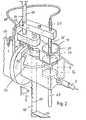
- Fig. 1 einen Teil der Kaffeemaschine, in schaubildlicher Darstellung, bei der der Kaffeezubringer von der Kaffeezubereitungsstelle weggeschwenkt worden ist, um eine neue Kaffeeportion aufzunehmen, und
- Fig. 2 eine gleiche Darstellung wie in Fig. 1, wobei sich aber der Kaffeezubringer an der Kaffeezubereitungsstelle befindet, und die Kaffeemaschine parat ist, Kaffee herzustellen.
- Fig. 1 shows a part of the coffee machine, in a diagrammatic representation, in which the coffee feeder has been pivoted away from the coffee preparation point in order to take up a new portion of coffee, and
- Fig. 2 is a same view as in Fig. 1, but with the coffee feeder at the coffee preparation site and the coffee machine is ready to make coffee.
Die Kaffeemaschine weist ein ortsfestes Gefäss 1 auf, an dem ein Kaffee-Zubereitungsblock 2 befestigt ist. Ein Lagerbock 3 ist über einer Platte 4 ebenfalls ortsfest am Gefäss 1 festgelegt. Vom Kaffee-Zubereitungsblock 2 führt eine Kaffeeleitung 5 weg, die in nicht dargestellter Weise ein oder zwei Kaffee-Auslässe aufweist, aus denen dann der fertige Kaffee von der Maschine abgelassen wird. Der Kaffee-Zubereitungsblock 2 ist noch mit einem schräg nach unten weisenden Abrutschblech 6 für den verbrauchten Kaffeepulver-Kuchen versehen. Unterhalb des Zubereitungsblockes 2 befindet sich ein Antriebsritzel 7, das in einem ortsfesten Lagerbock 8 in beiden Drehrichtungen drehbar gelagert ist. Diese vorerwähnten Bauteile 1 bis 8 sind also ortsfest abgestützt, verändern dadurch nicht ihre Lage, wobei lediglich der Bauteil 7 um seine Längsmittelachse drehbar ist. Im Innern des Zubereitungsblockes 2 befindet sich eine zylindrische Vertiefung 9, die oben an einer Fläche 10 des Blockes 2 ausmündet und einen Boden 11 hat, von der eine nicht dargestellte ringförmige Rinne mit dem Innern der Kaffeeleitung 5 in Verbindung steht. Am Kaffee-Zubereitungsblock 2 ist noch eine Tischplatte 12 befestigt. Am Gefäss 1 befindet sich ein Ablaufstutzen 13 für heisses Wasser. Alle Bauteile 1 bis 6 und 8 bis 13 sind also unbeweglich.The coffee machine has a
Die Kaffeemaschine hat einen Kaffeezubringer 14, einen Oberkolben 15 und einen Unterkolben 16. Es ist weiterhin eine Antriebsstange 17, ein Joch 18 und eine Schwenkstange 19 vorhanden. Diese Bauteile 14 bis 19 sind beweglich und in den Figuren 1 und 2 in verschiedenen Stellungen dargestellt.The coffee machine has a
Die Antriebsstange 17 ist im Lagerbock 3 heb-und senkbar verschiebbar geführt. Zusätzlich dient auch noch eine nicht dargestellte Bohrung im Kaffee-Zubereitungsblock 2 zur Führung dieser Antriebsstange 17. Die Antriebsstange 17 ist im unteren Bereich als Zahnstange ausgebildet, trägt also eine Verzahnung 18, in die das Antriebsritzel 7 eingreift. Am oberen Ende ist die Antriebsstange 17 mit dem Joch 18 verbunden. Am unteren Ende der Antriebsstange 17 ist noch ein Anschlag 20 befestigt. Die Antriebsstange 17 kann anstatt mechanisch auch hydraulisch betätigt sein.The
Der Kaffeezubringer 14 ist mit einer Durchgangsbohrung 21 versehen und ist auf der zylindrischen Antriebsstange 17 zwischen zwei Stellungen frei drehbar gelagert. In der einen Endstellung des Kaffeezubringers 14 nach Fig. 1 wird die Durchgangsbohrung 21 unten von der Tischplatte 12 begrenzt. In der anderen Endstellung des Kaffeezubringers 14 nach Fig. 2 liegt die Durchgangsbohrung 21 ausgerichtet zum Oberkolben 15, zum Unterkolben 16 und damit auch zur Vertiefung 9. Die erläuterte Schwenkbewegung des Kaffeezubringers 14 erfolgt über ein Zahnsegment 22, das mit einem Antriebsrad 23 kämmt.The
Die Schwenkstange 19 ist unten im Lagerbock 3 und oben im Joch 18 drehbar gelagert. Das Drehen der Schwenkstange 19 erfolgt über einen Wendeltrieb 24, 25. Letzterer umfasst einen um etwa 90° reichenden Schraubengang 24. Dieser Schraubengang 24 befindet sich in der Schwenkstange 19. Der Schraubengang 24 ist als Nut ausgebildet, die sich in der Mantelfläche der Schwenkstange 19 befindet. Am Joch 18 befindet sich ein Führungsorgan 25, das in den Schraubengang 24 eingreift. Dieses Führungsorgan 25 kann zum Beispiel ein Zapfen oder eine Rolle sein, die um eine Achse drehbar ist, die rechtwinklig zur Schwenkstange 19 liegt. Die Nut 24 stellt somit eine Kulissenführung des Wendeltriebs dar, und das Führungsorgan 25 ist eine in dieser Kulissenführung geführter Kulissenstein. Die Antriebsstange 17 ist im Lagerbock 3 und im Block 2 längs verschiebbar und undrehbar geführt.The
Eine den Oberkolben 15 tragende Kolbenstange 26 ist am Joch 18 befestigt. An letzterem ist weiterhin ein Zulaufstutzen 27 befestigt. Die beiden Stutzen 13 und 27 sind mit einer Leitung 28 verbunden. Im Innern der Kolbenstange 26 verläuft ein Längskanal, der unten von einer Stirnfläche des Oberkolbens 15 begrenzt ist. Diese Stirnfläche ist als Sieb ausgebildet. Die in Fig. 1 auf der Höhe der Blockfläche 10 liegende obere Stirnfläche des Unterkolbens 16 ist ebenfalls als Sieb ausgebildet. An der nicht dargestellten Unterseite des Unterkolbens 16 münden ein oder zwei dünne Bohrungen nach unten aus, deren Austrittsmündungen also dem Boden 11 der zylindrischen Vertiefung 9 zugewandt sind. Der Unterkolben 16 hat eine Kolbenstange 29, die keinen Längskanal aufweis. Diese Kolbenstange 29 liegt im Bewegungsweg des Anschlags 20, wenn sich die Antriebsstange 17 in die Stellung nach Fig. 1 nach oben bewegt. Die Arbeitsweise mit der erläuterten Kaffeemaschine ist folgendermassen:A
In Fig. 1 befindet sich der Kaffeezubringer 14 in einer zur Vertiefung 9 seitlich liegenden Stellung auf der Tischplatte 12, in der er durch eine nicht dargestellte Vorrichtung eine neue Portion Kaffeepulver erhält. Die obere Stirnfläche des Unterkolbens 16 befindet sich auf der Höhe der Fläche 10. Auf dieser oberen Stirnfläche des Unterkolbens 16 befindet sich ein nicht dargestellter Kaffeepulverkuchen, der also bei der vorhergehenden Kaffeezubereitung ausgepresst worden war. Wenn nunmehr Kaffee zubereitet werden soll, wird das Antriebsritzel 7 im Uhrzeigersinn angetrieben. Hierdurch wird die Antriebsstange 17 mit Joch 18 und Oberkolben 15 nach unten bewegt. Das im Joch 18 befestigte Führungsorgan 25 führt hierbei eine geradlinige Bewegung nach unten durch. Die im ortsfesten Lagerbock 3 nicht längs bewegbare aber drehbar gelagerte Schwenkstange 19 wird durch die Nut 24 in Fig. 1 in Richtung eines Pfeiles 30 gedreht. Hierdurch treibt das Antriebsrad 23 der Schwenkstange 19 über das Zahnradsegment 22 auf den Kaffeezubringer 14 und schwenkt diesen von der Stellung in Fig. 1 zur Stellung nach Fig. 2. Hierdurch gelangen Oberkolben 15, Durchgangsbohrung 21 und Vertiefung 9 in eine zueinander ausgerichtete Lage, so dass der Oberkolben 15 in die Durchgangsbohrung 21 des Kaffeezubringers 14 eintritt. Bei der erläuterten Schwenkbewegung des Kaffeezubringers 14 von der Stellung in Fig. 1 zur Stellung nach Fig. 2 wischt der Kaffeezubringer über die obere Stirnfläche des Unterkolbens 16 und über die Fläche 10 des Blocks 2 und schiebt hierbei den vorerwähnten verbrauchten Kaffeepulverkuchen von der Fläche 10 weg auf das Abrutschblech 6, zum Wegführen des verbrauchten Kaffeepulvers. Das neu zur Verfügung stehende Kaffeepulver befindet sich nunmehr innerhalb der Durchgangsbohrung 21 des Kaffeezubringers 14 und zwischen der unteren Stirnfläche des Oberkolbens 15 und der oberen Stirnfläche des Unterkolbens 16. Beim weiteren nach unten Bewegen der Antriebsstange 17 schiebt der Oberkolben 15 das neue Kaffeepulver und den Unterkolben 16 innerhalb der Vertiefung 9 nach unten in den Kaffee-Zubereitungsblock 2 gemäss der Stellung nach Fig. 2. Der Antrieb des Antriebsritzels 7 ist nunmehr beendet, und über ein weiteres Signal fliesst heisses Wasser zum Beispiel mit einem Druck von 8 bar über den Ablaufstutzen 13 durch die Leitung 28, durch den Zulaufstutzen 27 und durch die Kolbenstange 26 hindurch. Das heisse Wasser wird nunmehr durch das in der Vertiefung 9 befindliche und zwischen den beiden Siebflächen von Oberkolben 15 und Unterkolben 16 gehaltene Kaffeepulver hindurchgedrückt, worauf dann der fertige Kaffee über die Kaffeeleitung 5 wegfliesst. Die Durchflussrichtung des heissen Wassers und des fertigen Kaffees ist in Fig. 2 mit Pfeilen dargestellt.In Fig. 1, the
Soll neuer Kaffee zubereitet werden, erhält das Antriebsritzel 7 in Fig. 2 einen Antrieb entgegen dem Uhrzeigersinn, wodurch die Antriebsstange 17 mit Anschlag 20 nach oben geschoben werden. Das Joch 18 bewegt den Oberkolben 15 nach oben, und das Führungsorgan 25 verläuft zuerst innerhalb eines vertikalen Abschnitts der Nut 24. Wenn sich der Oberkolben 15 oberhalb des Kaffeezubringers 14 befindet, gelangt das Führungsorgan 25 auf den Schraubengang der Nut 24, wodurch die Schwenkstange 19 entgegen dem Uhrzeigersinn geschwenkt wird, wobei über das Zahnradgetriebe 22 und 23 der Kaffeezubringer 14 in die Stellung nach Fig. 1 geschwenkt wird. Beim weiteren nach oben Bewegen der Antriebsstange 17 gelangt ihr Anschlag 20 zur Anlage mit der Kolbenstange 29 des Unterkolbens 16 und hebt diesen innerhalb der Vertiefung 9 nach oben bis zur Stellung nach Fig. 1, wobei der verbrauchte Kaffeepulverkuchen auf der Höhe der Fläche 10 zu liegen kommt.If new coffee is to be prepared, the
Die beschriebene Kaffeemaschine ist nicht nur einfach aufgebaut und wirtschaftlich vorteilhaft, sondern bietet auch Betriebsvorteile. Dank der besonderen Ausbildung der Kaffeemaschine sind nämlich die Zeitabstände zwischen den aufeinanderfolgenden Kaffeezubereitungen relativ kurz. Bei gleichbleibender Dauer der Heiswasserdurchströmung durch das Kaffeepulver ist die für die Bewegung von Kaffeezubringer, Ober- und Unterkolben benötigte Zeit relativ kurz.The described coffee machine is not only simple and economically advantageous, but also offers operational advantages. Thanks to the special design of the coffee machine, the intervals between successive coffee preparations are relatively short. With the duration of hot water flow through the coffee powder remaining constant, the time required to move the coffee feeder, upper and lower pistons is relatively short.
Claims (9)
Priority Applications (5)
| Application Number | Priority Date | Filing Date | Title |
|---|---|---|---|
| EP85102303AEP0192797B1 (en) | 1985-03-01 | 1985-03-01 | Coffee-making machine |
| DE8585102303TDE3563509D1 (en) | 1985-03-01 | 1985-03-01 | Coffee-making machine |
| AT85102303TATE35373T1 (en) | 1985-03-01 | 1985-03-01 | COFFEE MACHINE. |
| ES552455AES8700917A1 (en) | 1985-03-01 | 1986-02-27 | Coffee-making machine. |
| JP61042049AJPS61253020A (en) | 1985-03-01 | 1986-02-28 | Coffee maker |
Applications Claiming Priority (1)
| Application Number | Priority Date | Filing Date | Title |
|---|---|---|---|
| EP85102303AEP0192797B1 (en) | 1985-03-01 | 1985-03-01 | Coffee-making machine |
Publications (2)
| Publication Number | Publication Date |
|---|---|
| EP0192797A1 EP0192797A1 (en) | 1986-09-03 |
| EP0192797B1true EP0192797B1 (en) | 1988-06-29 |
Family
ID=8193332
Family Applications (1)
| Application Number | Title | Priority Date | Filing Date |
|---|---|---|---|
| EP85102303AExpiredEP0192797B1 (en) | 1985-03-01 | 1985-03-01 | Coffee-making machine |
Country Status (5)
| Country | Link |
|---|---|
| EP (1) | EP0192797B1 (en) |
| JP (1) | JPS61253020A (en) |
| AT (1) | ATE35373T1 (en) |
| DE (1) | DE3563509D1 (en) |
| ES (1) | ES8700917A1 (en) |
Families Citing this family (11)
| Publication number | Priority date | Publication date | Assignee | Title |
|---|---|---|---|---|
| IT1198064B (en)* | 1986-10-31 | 1988-12-21 | Lucio Grossi | AUTOMATIC COMPACT MACHINE FOR THE PRODUCTION OF COFFEE, PARTICULARLY FOR DOMESTIC USE |
| JPH0327496A (en)* | 1989-06-23 | 1991-02-05 | Sanden Corp | Drink extracting device for automatic vending machine |
| JPH0327497A (en)* | 1989-06-23 | 1991-02-05 | Sanden Corp | Drink extracting device for automatic vending machine |
| ES2054573B1 (en)* | 1991-05-13 | 1995-02-01 | Azkoyen Hosteleria | IMPROVEMENTS INTRODUCED IN PATENT INVENTION N {9101161 BY: "IMPROVEMENTS IN AUTOMATIC COFFEE DISPENSING MACHINES. |
| IT1250447B (en)* | 1991-07-03 | 1995-04-07 | Lucio Grossi | AUTOMATIC MACHINE FOR THE PRODUCTION OF COFFEE WITH DIRECT CURRENT MOTOR OPERATION AND ENDLESS SCREWS. |
| DE4329597C1 (en)* | 1993-09-02 | 1994-12-15 | Hgz Maschinenbau Ag | Automated coffee machine |
| DE59504494D1 (en)* | 1995-07-31 | 1999-01-21 | Eugster Frismag Ag | Brewing head of an espresso machine |
| IT1293010B1 (en)* | 1997-06-19 | 1999-02-11 | Amico Srl | IMPROVEMENT OF AN AUTOMATIC DEVICE FOR THE PRODUCTION OF ESPRESSO COFFEE |
| DE102004023964B3 (en)* | 2004-05-14 | 2006-01-19 | HGZ Maschinenbau AG, Dällikon | The automated coffee machine |
| ATE392842T1 (en)* | 2004-11-04 | 2008-05-15 | Niro Plan Ag | BREWING GROUP FOR A COFFEE MACHINE |
| CH700894A2 (en)* | 2009-04-23 | 2010-10-29 | Jean-Paul In-Albon | Apparatus for producing coffee or other beverages. |
Family Cites Families (6)
| Publication number | Priority date | Publication date | Assignee | Title |
|---|---|---|---|---|
| CH521115A (en)* | 1970-01-08 | 1972-04-15 | Krumenacher Josef | coffee machine |
| AT313508B (en)* | 1970-12-01 | 1974-02-25 | Rossi Luigi | Machine for the preparation of infusions, in particular express coffee |
| CH590041A5 (en)* | 1975-05-20 | 1977-07-29 | Baumann Jules | Automatic coffee making machine - has linked pistons to eject old coffee grounds before new coffee powder is supplied |
| FR2338028A1 (en)* | 1976-01-16 | 1977-08-12 | Cuccia Bernard | Hand lever operated mechanism for coffee machine - has gears giving synchronised motions of horizontal and vertical racks controlling infusion cycle |
| CH641030A5 (en)* | 1980-10-03 | 1984-02-15 | Rost Kurt | METHOD FOR PRODUCING COFFEE AND COFFEE MACHINE FOR IMPLEMENTING THE SAME. |
| CH635740A5 (en)* | 1980-05-29 | 1983-04-29 | Rolland Versini | Device for a machine producing infusions of coffee |
- 1985
- 1985-03-01EPEP85102303Apatent/EP0192797B1/ennot_activeExpired
- 1985-03-01ATAT85102303Tpatent/ATE35373T1/enactive
- 1985-03-01DEDE8585102303Tpatent/DE3563509D1/ennot_activeExpired
- 1986
- 1986-02-27ESES552455Apatent/ES8700917A1/ennot_activeExpired
- 1986-02-28JPJP61042049Apatent/JPS61253020A/enactivePending
Also Published As
| Publication number | Publication date |
|---|---|
| ES552455A0 (en) | 1986-12-01 |
| ES8700917A1 (en) | 1986-12-01 |
| ATE35373T1 (en) | 1988-07-15 |
| JPS61253020A (en) | 1986-11-10 |
| DE3563509D1 (en) | 1988-08-04 |
| EP0192797A1 (en) | 1986-09-03 |
Similar Documents
| Publication | Publication Date | Title |
|---|---|---|
| DE3152397C2 (en) | Coffee brewing device | |
| EP0192797B1 (en) | Coffee-making machine | |
| DE3613074A1 (en) | SPRAYLING REMOVAL DEVICE FOR INJECTION MOLDING MACHINES | |
| DE3851006T2 (en) | Device for cooling and / or drying bulk goods. | |
| DE8813730U1 (en) | Assembly and/or production line section with transport plates carrying workpieces | |
| DE1803819C3 (en) | concrete pump | |
| DE69410401T2 (en) | Belt conveyor, in particular for a ready-mixed concrete mixer | |
| CH658583A5 (en) | Coffee machine | |
| DE3305893C2 (en) | ||
| DE2928950C2 (en) | Device for removing fermentation fodder from mobile silos | |
| DE1586108A1 (en) | Device for continuously filling quantities of liquid into containers | |
| DE1951381C3 (en) | Device for controlling positive displacement pumps | |
| EP0829441B1 (en) | Device for ejecting stacked and printed sheets | |
| DD208596A5 (en) | EMISSION CONTROL DEVICE FOR STICKY GOOD FROM A STANDING CONTAINER | |
| DE2241941C3 (en) | Door hinge with two hinge links | |
| DE2532136A1 (en) | Rotary slide valve control for cylinder drive - has cylindrical rotary piston with two ring grooves, two cut outs and connecting bores | |
| DE3541588A1 (en) | Device for threading material webs in rotary printing machines | |
| DE1482916B2 (en) | MAWING MACHINE WITH A MAWING TABLE | |
| DE19822779C1 (en) | Attaching machine | |
| DE2461400C3 (en) | Protection device for punch presses, punching, etc. | |
| DE228398C (en) | ||
| DE2847614A1 (en) | TURN-SLIDE LOCK FOR GIESSPFANNEN O.AE. | |
| DE1480604B2 (en) | PIVOTING SLIDING DOOR | |
| DE3117166A1 (en) | Lever mechanism for a ceramic plate control of a sanitary mixer unit | |
| DE1933056C (en) | Device for stepless adjustment of the return ratio of a destination column |
Legal Events
| Date | Code | Title | Description |
|---|---|---|---|
| PUAI | Public reference made under article 153(3) epc to a published international application that has entered the european phase | Free format text:ORIGINAL CODE: 0009012 | |
| AK | Designated contracting states | Kind code of ref document:A1 Designated state(s):AT BE DE FR GB IT LU NL SE | |
| 17P | Request for examination filed | Effective date:19861023 | |
| 17Q | First examination report despatched | Effective date:19870723 | |
| ITF | It: translation for a ep patent filed | ||
| GRAA | (expected) grant | Free format text:ORIGINAL CODE: 0009210 | |
| AK | Designated contracting states | Kind code of ref document:B1 Designated state(s):AT BE DE FR GB IT LU NL SE | |
| REF | Corresponds to: | Ref document number:35373 Country of ref document:AT Date of ref document:19880715 Kind code of ref document:T | |
| GBT | Gb: translation of ep patent filed (gb section 77(6)(a)/1977) | ||
| REF | Corresponds to: | Ref document number:3563509 Country of ref document:DE Date of ref document:19880804 | |
| ET | Fr: translation filed | ||
| PLBE | No opposition filed within time limit | Free format text:ORIGINAL CODE: 0009261 | |
| STAA | Information on the status of an ep patent application or granted ep patent | Free format text:STATUS: NO OPPOSITION FILED WITHIN TIME LIMIT | |
| 26N | No opposition filed | ||
| ITTA | It: last paid annual fee | ||
| EPTA | Lu: last paid annual fee | ||
| EAL | Se: european patent in force in sweden | Ref document number:85102303.6 | |
| PGFP | Annual fee paid to national office [announced via postgrant information from national office to epo] | Ref country code:DE Payment date:19980221 Year of fee payment:14 | |
| PGFP | Annual fee paid to national office [announced via postgrant information from national office to epo] | Ref country code:AT Payment date:19980223 Year of fee payment:14 | |
| PGFP | Annual fee paid to national office [announced via postgrant information from national office to epo] | Ref country code:GB Payment date:19980226 Year of fee payment:14 | |
| PGFP | Annual fee paid to national office [announced via postgrant information from national office to epo] | Ref country code:LU Payment date:19980303 Year of fee payment:14 | |
| PGFP | Annual fee paid to national office [announced via postgrant information from national office to epo] | Ref country code:SE Payment date:19980317 Year of fee payment:14 | |
| PGFP | Annual fee paid to national office [announced via postgrant information from national office to epo] | Ref country code:BE Payment date:19980319 Year of fee payment:14 | |
| PGFP | Annual fee paid to national office [announced via postgrant information from national office to epo] | Ref country code:NL Payment date:19980330 Year of fee payment:14 Ref country code:FR Payment date:19980330 Year of fee payment:14 | |
| PG25 | Lapsed in a contracting state [announced via postgrant information from national office to epo] | Ref country code:LU Free format text:LAPSE BECAUSE OF NON-PAYMENT OF DUE FEES Effective date:19990301 Ref country code:GB Free format text:LAPSE BECAUSE OF NON-PAYMENT OF DUE FEES Effective date:19990301 Ref country code:AT Free format text:LAPSE BECAUSE OF NON-PAYMENT OF DUE FEES Effective date:19990301 | |
| PG25 | Lapsed in a contracting state [announced via postgrant information from national office to epo] | Ref country code:SE Free format text:LAPSE BECAUSE OF NON-PAYMENT OF DUE FEES Effective date:19990302 | |
| PG25 | Lapsed in a contracting state [announced via postgrant information from national office to epo] | Ref country code:BE Free format text:LAPSE BECAUSE OF NON-PAYMENT OF DUE FEES Effective date:19990331 | |
| BERE | Be: lapsed | Owner name:BAUMANN JULES (JUN) Effective date:19990331 | |
| PG25 | Lapsed in a contracting state [announced via postgrant information from national office to epo] | Ref country code:NL Free format text:LAPSE BECAUSE OF NON-PAYMENT OF DUE FEES Effective date:19991001 | |
| GBPC | Gb: european patent ceased through non-payment of renewal fee | Effective date:19990301 | |
| EUG | Se: european patent has lapsed | Ref document number:85102303.6 | |
| PG25 | Lapsed in a contracting state [announced via postgrant information from national office to epo] | Ref country code:FR Free format text:LAPSE BECAUSE OF NON-PAYMENT OF DUE FEES Effective date:19991130 | |
| NLV4 | Nl: lapsed or anulled due to non-payment of the annual fee | Effective date:19991001 | |
| EUG | Se: european patent has lapsed | Ref document number:85102303.6 | |
| REG | Reference to a national code | Ref country code:FR Ref legal event code:ST | |
| PG25 | Lapsed in a contracting state [announced via postgrant information from national office to epo] | Ref country code:DE Free format text:LAPSE BECAUSE OF NON-PAYMENT OF DUE FEES Effective date:20000101 |