EP0191688A1 - Surgical apparatus for corneal curvature adjustment - Google Patents
Surgical apparatus for corneal curvature adjustmentDownload PDFInfo
- Publication number
- EP0191688A1 EP0191688A1EP86400192AEP86400192AEP0191688A1EP 0191688 A1EP0191688 A1EP 0191688A1EP 86400192 AEP86400192 AEP 86400192AEP 86400192 AEP86400192 AEP 86400192AEP 0191688 A1EP0191688 A1EP 0191688A1
- Authority
- EP
- European Patent Office
- Prior art keywords
- cornea
- diaphragm
- optical system
- spot
- area
- Prior art date
- Legal status (The legal status is an assumption and is not a legal conclusion. Google has not performed a legal analysis and makes no representation as to the accuracy of the status listed.)
- Granted
Links
- 210000004087corneaAnatomy0.000claimsabstractdescription64
- 230000003287optical effectEffects0.000claimsabstractdescription43
- 238000002679ablationMethods0.000claimsabstractdescription12
- 239000000463materialSubstances0.000claimsabstractdescription9
- 241000446313LamellaSpecies0.000claimsdescription12
- 238000006073displacement reactionMethods0.000claimsdescription12
- 238000005259measurementMethods0.000claimsdescription3
- 238000006303photolysis reactionMethods0.000claimsdescription3
- 238000012544monitoring processMethods0.000claimsdescription2
- 230000000694effectsEffects0.000abstract1
- 238000011282treatmentMethods0.000description14
- 208000001491myopiaDiseases0.000description13
- 238000000034methodMethods0.000description12
- 230000004379myopiaEffects0.000description10
- 201000009310astigmatismDiseases0.000description9
- 201000006318hyperopiaDiseases0.000description8
- 230000004305hyperopiaEffects0.000description8
- 238000012937correctionMethods0.000description6
- 208000035943AphagiaDiseases0.000description5
- 206010020675HypermetropiaDiseases0.000description5
- 238000012986modificationMethods0.000description5
- 230000004048modificationEffects0.000description5
- 230000007423decreaseEffects0.000description4
- 238000010586diagramMethods0.000description4
- 230000008569processEffects0.000description4
- 230000000472traumatic effectEffects0.000description4
- 230000009471actionEffects0.000description3
- 230000009467reductionEffects0.000description3
- 241001080024TellesSpecies0.000description2
- MARDFMMXBWIRTK-UHFFFAOYSA-N[F].[Ar]Chemical compound[F].[Ar]MARDFMMXBWIRTK-UHFFFAOYSA-N0.000description2
- 230000003247decreasing effectEffects0.000description2
- 230000007547defectEffects0.000description2
- CPBQJMYROZQQJC-UHFFFAOYSA-Nhelium neonChemical compound[He].[Ne]CPBQJMYROZQQJC-UHFFFAOYSA-N0.000description2
- 238000003754machiningMethods0.000description2
- 238000012423maintenanceMethods0.000description2
- 239000000203mixtureSubstances0.000description2
- 230000005855radiationEffects0.000description2
- 206010001488AggressionDiseases0.000description1
- 206010002945AphakiaDiseases0.000description1
- 241000135309ProcessusSpecies0.000description1
- 238000013459approachMethods0.000description1
- 238000012550auditMethods0.000description1
- 210000004027cellAnatomy0.000description1
- 230000008859changeEffects0.000description1
- 238000013461designMethods0.000description1
- 230000008030eliminationEffects0.000description1
- 238000003379elimination reactionMethods0.000description1
- 229940082150encoreDrugs0.000description1
- 230000008014freezingEffects0.000description1
- 238000007710freezingMethods0.000description1
- 238000002430laser surgeryMethods0.000description1
- 230000005499meniscusEffects0.000description1
- 238000012552reviewMethods0.000description1
- 239000007787solidSubstances0.000description1
Images


Classifications
- A—HUMAN NECESSITIES
- A61—MEDICAL OR VETERINARY SCIENCE; HYGIENE
- A61F—FILTERS IMPLANTABLE INTO BLOOD VESSELS; PROSTHESES; DEVICES PROVIDING PATENCY TO, OR PREVENTING COLLAPSING OF, TUBULAR STRUCTURES OF THE BODY, e.g. STENTS; ORTHOPAEDIC, NURSING OR CONTRACEPTIVE DEVICES; FOMENTATION; TREATMENT OR PROTECTION OF EYES OR EARS; BANDAGES, DRESSINGS OR ABSORBENT PADS; FIRST-AID KITS
- A61F9/00—Methods or devices for treatment of the eyes; Devices for putting in contact-lenses; Devices to correct squinting; Apparatus to guide the blind; Protective devices for the eyes, carried on the body or in the hand
- A61F9/007—Methods or devices for eye surgery
- A61F9/008—Methods or devices for eye surgery using laser
- A61F9/00802—Methods or devices for eye surgery using laser for photoablation
- A61F9/00804—Refractive treatments
- A—HUMAN NECESSITIES
- A61—MEDICAL OR VETERINARY SCIENCE; HYGIENE
- A61F—FILTERS IMPLANTABLE INTO BLOOD VESSELS; PROSTHESES; DEVICES PROVIDING PATENCY TO, OR PREVENTING COLLAPSING OF, TUBULAR STRUCTURES OF THE BODY, e.g. STENTS; ORTHOPAEDIC, NURSING OR CONTRACEPTIVE DEVICES; FOMENTATION; TREATMENT OR PROTECTION OF EYES OR EARS; BANDAGES, DRESSINGS OR ABSORBENT PADS; FIRST-AID KITS
- A61F9/00—Methods or devices for treatment of the eyes; Devices for putting in contact-lenses; Devices to correct squinting; Apparatus to guide the blind; Protective devices for the eyes, carried on the body or in the hand
- A61F9/007—Methods or devices for eye surgery
- A61F9/008—Methods or devices for eye surgery using laser
- A61F9/00802—Methods or devices for eye surgery using laser for photoablation
- A61F9/00817—Beam shaping with masks
- A—HUMAN NECESSITIES
- A61—MEDICAL OR VETERINARY SCIENCE; HYGIENE
- A61F—FILTERS IMPLANTABLE INTO BLOOD VESSELS; PROSTHESES; DEVICES PROVIDING PATENCY TO, OR PREVENTING COLLAPSING OF, TUBULAR STRUCTURES OF THE BODY, e.g. STENTS; ORTHOPAEDIC, NURSING OR CONTRACEPTIVE DEVICES; FOMENTATION; TREATMENT OR PROTECTION OF EYES OR EARS; BANDAGES, DRESSINGS OR ABSORBENT PADS; FIRST-AID KITS
- A61F9/00—Methods or devices for treatment of the eyes; Devices for putting in contact-lenses; Devices to correct squinting; Apparatus to guide the blind; Protective devices for the eyes, carried on the body or in the hand
- A61F9/007—Methods or devices for eye surgery
- A61F9/008—Methods or devices for eye surgery using laser
- A61F2009/00861—Methods or devices for eye surgery using laser adapted for treatment at a particular location
- A61F2009/00872—Cornea
Definitions
- the present inventionrelates to a surgical device intended to modify the curvature of the ocular cornea, whether this cornea is carried by a living being, or else has been previously removed from a living being.
- the object of the present inventionis to remedy the drawbacks of these known methods. It relates to a surgical device making it possible to modify the curvature of the cornea in a non-traumatic, rapid and easy way to treat conditions as different as myopia, farsightedness, aphagia, and astigmatism.
- the surgical deviceintended to modify at least in part the curvature of the ocular cornea by ablation of an area of the latter in the form of a lenticular strip of radially variable thickness, and comprising a light source capable of emitting a beam whose wavelength is close to 0.2 micrometers to allow photodecomposition of the corneal material, as well as an optical system directing said beam onto said zone of cornea to be eliminated and forming therein a light spot on a part of said zone is remarkable in that it includes means for making said light spot explore all of said zone to be eliminated, so that the parts of said zone are all the more long exposed to said beam that they correspond to greater thicknesses of said lenticular lamella and vice versa.
- the deviceAccording to the first mode, the light spot being constantly centered on the optical axis of the eye, the device according to the invention comprises exploration means for gradually varying the area of this spot on the cornea: This mode applies to almost all treatments. Indeed :
- the treatment of myopia - correctable by a reduction in the curvature of the cornea -requires the ablation of a lens-shaped lamella, thicker in its center (near the optical axis of the eye) than 'on its outskirts. Consequently, in this case, the density of light energy received by the cornea must go decreasing from the center towards the periphery, or increasing from the periphery towards the center.
- the optical system of the deviceforms, on the cornea, a circular light spot and said means of exploration gradually vary the area of said spot from a small central spot to the 'total area of the area to be eliminated, or vice versa.
- the variation of the area of said spottakes place in the direction of enlargement, that is to say from the center towards the periphery, the duration of exposure to the light beam decreases as and as we move away from the center.
- the exploration of the area to be eliminatedtakes place from the periphery towards the center, the duration of exposure to the light beam increases as one approaches the center.
- the variation in the exposure timeis adjusted to respect the desired variation in curvature.
- the optical system of the apparatusforms, on the cornea, an annular light spot and said exploration means gradually vary the area of said spot, at least by varying the internal diameter of this one.
- this variation in area of the annular spotis adjusted so that the desired profile modification is obtained. It can be carried out both in the direction of enlargement and in that of reduction.
- the optical system of the device according to the inventionforms on the cornea an elongated light spot whose long rectilinear sides are perpendicular to said particular meridian and said exploration means gradually vary the area of said spot, at least by varying the length of the short sides thereof.
- the variation in areacan result from an enlargement or a reduction, as long as said variation is such (as a function of time) that it communicates to the cornea the desired modification of curvature.
- thiscomprises exploration means for making said spot occupy, which then has a simple geometric shape delimited by segments straight, for example rectangular, a plurality of successive positions, the duration of the maintenance of the spot in one of these positions depending on the thickness of the corneal material to be removed at the location. of it.
- This second mode of modification of curvature according to the inventionis therefore particularly suitable for the correction of astigmatism, as a variant to the first mode described above for this purpose. It is then advantageous, in order to facilitate the juxtaposition process, for said spot to cover the entire width of the area to be eliminated and for said exploration means to move this spot parallel to itself in a direction perpendicular to this width.
- said exploration meanscomprise at least one screen or a diaphragm and displacement means for generating relative displacement between said optical system and at least one of said screens or diaphragms, the speed of this relative displacement corresponding to the radial variation in thickness of said strip to be eliminated.
- the direction of this relative movementcan be parallel or transverse to said beam.
- said optical system and said screens and / or diaphragmsare mounted on an optical bench.
- the device according to the inventionmay comprise a fixed diaphragm, an optical system also fixed and a mobile screen pierced with a slot.
- This slotis transverse to the direction of movement of said screen which can be moved either parallel to itself, or in its own plane.
- the apparatusthen advantageously comprises means for adjusting the orientation of said slot in the plane of said mobile screen.
- an electronic computercontrolling said light source and said exploration means as a function of the radial variation in thickness desired for said strip to be eliminated.
- the apparatusthen further comprises a keratometer capable of monitoring the change in curvature of the cornea and of sending its measurements to said computer.
- An auxiliary laser generatorfor example of the helium-neon type, is also provided, in order to facilitate alignment of the ablation beam with respect to said cornea.
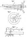
- FIGS. 1 and 2the principle according to which the apparatus according to the present invention is illustrated, in the case of the treatment of myopia.
- This lenticular strip 2is centered on the optical axis X-X of the eye and has in its center a maximum thickness em, which decreases towards its periphery 3, as a function of the radial distance R from the axis X-X.
- the progressiveness of the variation of the thickness e of said strip 2 as a function of the variation of the radial distance Ris determined by the desired curvature correction.
- a light beam 4 of circular sectionis used, the wavelength of which is at most equal to 0.2 micrometer and which has a constant energy density, transverse to its direction.
- the light beam 4is directed onto the cornea 1 and centered on the optical axis XX:
- the radius r of the spot formed by said beam 4 on the cornea 1is varied, as a function of time t, according to a law making it possible to satisfy the desired law e (R). , i.e. such that, for each value 0, ..., r1, ..., r2, ..., rm of the radius of said spot, a depth of elimination of the cornea is obtained corresponding to thicknesses em, ..., e1, ... e2, ... 0 of said strip 2 ..
- the variation r (t) of the radius r as a function of time tcan be carried out from the maximum value rm of the radius r to zero, or else from zero to the maximum value rm.
- the ablation of the desired lamella 2is obtained by forming, on the cornea 1, a circular luminous spot and by varying the radius of this spot as a function of time, in order to obtain the desired e (R) law.
- the device 5, shown in FIG. 3,comprises an optical bench 6 along which a carriage 7 can move in both directions (arrows F), under the action of drive means 8, comprising for example an electric motor 9 causing an endless screw 10 to rotate, cooperating with a nut 11 linked to said carriage 7.
- drive means 8comprising for example an electric motor 9 causing an endless screw 10 to rotate, cooperating with a nut 11 linked to said carriage 7.
- the carriage 7carries an optical system shown in the form of a lens 12 generating the light beam 4 and capable of forming a light spot on the cornea 1.
- a lens 12generating the light beam 4 and capable of forming a light spot on the cornea 1.
- a fixed diaphragm 13makes it possible to address the lens 12 a homogeneous parallel light beam 27 of circular section, from which the beam 4 comes.
- the lens 12is mounted in a fixed position on the bench 6.
- an additional circular diaphragm 15is provided mounted on the carriage 7.
- the strip 16is centered on the optical axis X-X of the eye and has a thickness which increases towards its periphery 17.
- the lamella 16can be ablated, by varying the internal radius of said spot as a function of time, in order to comply with the law of variation of the thickness of said strip 16, parallel to the radial direction R.
- the duration of exposure to the beam 4must last as much longer as one moves away from the optical axis X-X.
- one or the other of the devices 18 and 19 of FIGS. 7 or 8can be used.
- the device 18is identical to the device 5 of FIG. 3, with the difference that the central part of the lens 12 is obscured by a circular central screen 20. Consequently, when the drive means 8 move the lens 12 along the bench 6, this results in a variation in the size of the shadow cast by said screen 20 on the central part of said cornea 1.
- the speed of movement of the assembly 12.20 along the bench 6by controlling the means 8
- the exposure time of the cornea 1 to the beam 4is therefore adjusted, as a function of the radial distance, in order to obtain the ablation of the strip 16 of the desired profile.
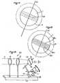
- FIG. 9there is shown partially and schematically in perspective a device 22 according to the invention, intended to correct astigmatism.
- This device 22is identical to the device 14 of FIG. 4, except that the circular diaphragm 15 is replaced by a screen 23, pierced with a rectilinear slot 24.
- the rectilinear slot 24is orthogonal to a predetermined direction 25 .
- an elongated light spot 26is formed on the cornea whose long sides are rectilinear and orthogonal to said predetermined direction 25, which corresponds to the trace of the meridian of the eye according to which. performed the curvature correction. Laterally, the task 26 is limited by the corresponding portion of the circular line 41 determined by the diaphragm 13.
- the area of the spot 26 on the cornea 1increases and / or decreases as a function of the direction of said movement, so that it is possible to ablate a coverslip corresponding to the desired correction.
- the devices 5,14,18,19 and 22 shown and described with reference to Figures 3,4,7,8 and 9explore the cornea 1 by means of a variation of the area of a light spot. However, such an exploration can also be carried out by scanning a spot whose dimension parallel to the scan remains constant.
- FIG 10there is illustrated a variant 29 of the device according to the invention.
- the screen 23is mounted on a controllable device, so that it can be moved in its plane.
- the exploration of the cornea zone 1 to be eliminatedis carried out by giving the light spot 28 formed by the slot 24 on said cornea a plurality of successive positions 28.1, ..., 28.n like this. is shown in Figure 12.
- the duration of the maintenance of the spot 28 in each of its positions 28.1 to 28.ndepends on the thickness of corneal material to be removed at the location of the corresponding position.
- the screen 23can not only move in its plane, but also, thanks to an articulation device 31 of its support 30, be oriented so that the direction of the slot 24 is adjustable.
- the computer 34is programmed to control the device 32 according to the law of variation in thickness desired for the lamella to be eliminated from the cornea 1 and it executes the corresponding sequences of operations taking into account the information supplied to it by the keratometer 37 and the photodetector 35.
- the device 39includes means for automatic emergency area, if necessary.
Landscapes
- Health & Medical Sciences (AREA)
- Ophthalmology & Optometry (AREA)
- Heart & Thoracic Surgery (AREA)
- Animal Behavior & Ethology (AREA)
- Optics & Photonics (AREA)
- Surgery (AREA)
- Engineering & Computer Science (AREA)
- Biomedical Technology (AREA)
- Physics & Mathematics (AREA)
- Vascular Medicine (AREA)
- Life Sciences & Earth Sciences (AREA)
- Nuclear Medicine, Radiotherapy & Molecular Imaging (AREA)
- General Health & Medical Sciences (AREA)
- Public Health (AREA)
- Veterinary Medicine (AREA)
- Laser Surgery Devices (AREA)
- Rehabilitation Tools (AREA)
- Eye Examination Apparatus (AREA)
- Materials For Medical Uses (AREA)
Abstract
Description
Translated fromFrenchLa présente invention concerne un appareil chirurgical destiné à modifier la courbure de la cornée oculaire, que cette cornée soit portée par un être vivant, ou bien ait été préalablement prélevée sur un être vivant.The present invention relates to a surgical device intended to modify the curvature of the ocular cornea, whether this cornea is carried by a living being, or else has been previously removed from a living being.
On sait que certaines affections, telles que la myopie, l'hypermétropie et l'astigmatisme, peuvent être traitées par modification de la courbure de la cornée. Par ailleurs, d'autres affections, telles que l'aphaquie, peuvent être traitées au moins en partie par correction de ladite courbure. Par suite, on a déjà pensé à des méthodes permettant de modifier la courbure de la cornée.It is known that certain conditions, such as myopia, hyperopia and astigmatism, can be treated by modifying the curvature of the cornea. Furthermore, other ailments, such as aphagia, can be treated at least in part by correcting said curvature. As a result, we have already thought of methods for modifying the curvature of the cornea.
Ces méthodes connues sont essentiellement de deux types :
- - le premier consiste à prélever, à l'aide d'un instrument mécanique coupant, une lentille plan-convexe de la cornée, à congeler cette lentille pour la rendre solide et à usiner, au moyen d'un tour, ladite lentille solidifiée afin d'en éliminer une zone en forme de lamelle bombée d'épaisseur variable. Après usinage, la lentille usinée est décongelée, puis recousue à son emplacement initial. Une telle méthode est longue, onéreuse et traumatisante pour le patient. De plus, elle ne permet de soigner que des affections de révolution autour de l'axe optique de l'oeil, telles que la myopie et l'hypermétropie, et non pas l'astigmatisme qui ne présente pas de symétrie de révolution ;
- - le second type de méthodes a pour mode opératoire de pratiquer dans la cornée, à l'extérieur de la zone optique, des fentes radiales au moyen d'un bistouri ou d'un faisceau laser. A cause de ces fentes, la partie de cornée incisée s'aplatit, modifiant de ce fait la courbure générale. Quoique moins traumatisantes que les méthodes du premier type, celles du second type restent violentes à cause des scarifications obligatoires de la cornée. De plus, les possibilités de ces dernières méthodes restent limitées.
- - the first consists of taking, using a mechanical cutting instrument, a plano-convex lens of the cornea, freezing this lens to make it solid and machining, by means of a lathe, said solidified lens so to eliminate a zone in the form of a curved lamella of variable thickness. After machining, the machined lens is thawed, then stitched back to its original location. Such a method is long, expensive and traumatic for the patient. In addition, it only treats affections of revolution around the optical axis of the eye, such as myopia and hyperopia, and not astigmatism which does not have symmetry of revolution;
- - The second type of method has the operating mode of practicing in the cornea, outside the optical zone, radial slits by means of a scalpel or a laser beam. Because of these slits, the incised part of the cornea flattens, thereby modifying the general curvature. Although less traumatic than methods of the first type, those of the second type remain violent because of the obligatory scarifications of the cornea. In addition, the possibilities of these latter methods remain limited.
Par ailleurs, dans l'article "Excimer laser surgery of the cornea" daté du 21 Septembre 1983 et paru dans la revue "AMERICAN JOURNAL OF OPHTHALMOLOGY" Vol.96 n° 6, pages 710 à 715 de Décembre 1983, Stephen L. TROKEL, R. SRINIVASAN et BODIL BRAREN décrivent l'utilisation d'un laser à excimère pour éliminer la matière cornéenne par photodécomposition. Dans cet article, il est recommandé d'utiliser un rayonnement ultraviolet dont la longueur d'onde est égale à 0,193 micromètre et il est précisé que, pour modifier la courbure de la cornée, on peut former sur ladite cornée, à l'aide dudit rayonnement, une taché circulaire dont "l'intensité varie du centre vers la périphérie, de sorte que l'on enlève plus de matière soit au centre, soit à la périphérie, en fonction de la distribution de lumière". On peut ainsi augmenter ou diminuer la courbure de la cornée.In addition, in the article "Excimer laser surgery of the cornea" dated September 21, 1983 and published in the review "AMERICAN JOURNAL OF OPHTHALMOLOGY" Vol.96 n ° 6, pages 710 to 715 of December 1983, Stephen L. TROKEL , R. SRINIVASAN and BODIL BRAREN describe the use of an excimer laser to remove corneal matter by photodecomposition. In this article, it is recommended to use an ultraviolet radiation whose wavelength is equal to 0.193 micrometer and it is specified that, to modify the curvature of the cornea, one can form on said cornea, using said radiation, a circular spot whose "intensity varies from the center to the periphery, so that more material is removed either at the center or at the periphery, depending on the light distribution". It is thus possible to increase or decrease the curvature of the cornea.
Cette dernière méthode est particulièrement intéressante, mais elle est difficile à mettre en oeuvre, car elle nécessite des moyens permettant de faire varier l'intensité lumineuse en correspondance avec la courbure cornéenne désirée. La réalisation technologique de tels moyens parait difficile, pour ne pas dire impossible.This last method is particularly interesting, but it is difficult to implement, because it requires means making it possible to vary the light intensity in correspondence with the desired corneal curvature. The technological realization of such means seems difficult, if not impossible.
La présente invention a pour objet de remédier aux inconvénients de ces méthodes connues. Elle concerne un appareil chirurgical permettant de modifier la courbure de la cornée de façon non traumatisante, rapide et aisée pour traiter des affections aussi différentes que la myopie, l'hypermétropie, l'aphaquie, et l'astigmatisme.The object of the present invention is to remedy the drawbacks of these known methods. It relates to a surgical device making it possible to modify the curvature of the cornea in a non-traumatic, rapid and easy way to treat conditions as different as myopia, farsightedness, aphagia, and astigmatism.
A ces fins, selon l'invention, l'appareil chirurgical destiné à modifier au moins en partie la courbure de la cornée oculaire par ablation d'une zone de celle-ci en forme de lamelle lenticulaire d'épaisseur radialement variable, et comportant une source de lumière susceptible d'émettre un faisceau dont la longueur d'onde est voisine de 0,2 micromètre pour permettre la photodécomposition de la matière cornéenne, ainsi qu'un système optique dirigeant ledit faisceau sur ladite zone de cornée à éliminer et y formant une tache lumineuse sur une partie de ladite zone, est remarquable en ce qu'il comporte des moyens pour faire explorer, par ladite tache lumineuse, la totalité de ladite zone à éliminer, de façon que les parties de ladite zone soient d'autant plus longtemps exposées audit faisceau qu'elles correspondent à des épaisseurs plus grandes de ladite lamelle lenticulaire et vice-versa.For these purposes, according to the invention, the surgical device intended to modify at least in part the curvature of the ocular cornea by ablation of an area of the latter in the form of a lenticular strip of radially variable thickness, and comprising a light source capable of emitting a beam whose wavelength is close to 0.2 micrometers to allow photodecomposition of the corneal material, as well as an optical system directing said beam onto said zone of cornea to be eliminated and forming therein a light spot on a part of said zone is remarkable in that it includes means for making said light spot explore all of said zone to be eliminated, so that the parts of said zone are all the more long exposed to said beam that they correspond to greater thicknesses of said lenticular lamella and vice versa.
Ainsi, on peut obtenir l'ablation de la matière cornéenne sans scarification par un processus photochimique, particulièrement peu traumatisant pour le patient sans avoir à concevoir des moyens susceptibles de faire varier radialement l'intensité du faisceau laser.Thus, one can obtain the ablation of the corneal material without scarification by a photochemical process, particularly little traumatic for the patient without having to design means capable of varying the intensity of the laser beam radially.
En effet, puisque selon l'invention, on fait en sorte que les parties de la cornée correspondant à de grandes épaisseurs à éliminer soient plus exposées au faisceau lumineux que les parties de cette même cornée correspondant à de petites épaisseurs à éliminer, on obtient une .ablation photochimique différentielle de la cornée, permettant de modifier la courbure de celle-ci, puisque ces parties épaisses reçoivent plus d'énergie lumineuse que ces parties minces.Indeed, since according to the invention, it is made so that the parts of the cornea corresponding to large thicknesses to be eliminated are more exposed to the light beam than the parts of this same cornea corresponding to small thicknesses to be eliminated, one obtains a . Differential photochemical ablation of the cornea, making it possible to modify its curvature, since these thick parts receive more light energy than these thin parts.
La progressivité de cette ablation photochimique différentielle dépend alors uniquement de la progressivité de l'exploration de la totalité de la zone à éliminer par ladite tache lumineuse.The progressiveness of this differential photochemical ablation then depends only on the progressiveness of the exploration of the entire area to be eliminated by said light spot.
Pour obtenir le maximum de progressivité d'exploration et donc de précision dans la modification de la courbure de la cornée, on prévoit essentiellement, selon l'invention, deux modes d'exploration :To obtain the maximum progressivity of exploration and therefore of precision in the modification of the curvature of the cornea, two modes of exploration are essentially provided, according to the invention:
1 - Selon le premier mode, la tache.lumineuse étant constamment centrée sur l'axe optique de l'oeil, l'appareil conforme à l'invention comporte des moyens d'exploration pour faire varier progressivement l'aire de cette tache sur la cornée: Ce mode s'applique pratiquement à tous les traitements. En effet :1 - According to the first mode, the light spot being constantly centered on the optical axis of the eye, the device according to the invention comprises exploration means for gradually varying the area of this spot on the cornea: This mode applies to almost all treatments. Indeed :
a) le traitement de la myopie - corrigible par une réduction de la courbure de la cornée - nécessite l'ablation d'une lamelle en forme de lentille, plus épaisse en son centre (voisinage de l'axe optique de l'oeil) qu'à sa périphérie. Par suite, dans ce cas, il faut que la densité d'énergie lumineuse reçue par la cornée aille en décroissant du centre vers la périphérie, ou en croissant de la périphérie vers le centre.a) the treatment of myopia - correctable by a reduction in the curvature of the cornea - requires the ablation of a lens-shaped lamella, thicker in its center (near the optical axis of the eye) than 'on its outskirts. Consequently, in this case, the density of light energy received by the cornea must go decreasing from the center towards the periphery, or increasing from the periphery towards the center.
Pour ce faire, le système optique de l'appareil conforme à l'invention forme, sur la cornée, une tache lumineuse circulaire et lesdits moyens d'exploration font varier progressivement l'aire de ladite tache depuis une petite tache centrale jusqu'à l'aire totale de la zone à éliminer, ou vice-versa. Dans le cas où la variation d'aire de ladite tache s'effectue dans le sens de l'agrandissement, c'est-à-dire du centre vers la périphérie, la durée d'exposition au faisceau lumineux décroît au fur et à mesure que l'on s'éloigne du centre. Au contraire, lorsque l'exploraiton de la zone à éliminer a lieu depuis la périphérie vers le centre, la durée d'exposition au faisceau lumineux croît au fur et à mesure que l'on se rapproche du centre. Bien entendu, dans l'un et l'autre cas, la variation de la durée d'exposition est réglée pour respecter la variation de courbure désirée.To do this, the optical system of the device according to the invention forms, on the cornea, a circular light spot and said means of exploration gradually vary the area of said spot from a small central spot to the 'total area of the area to be eliminated, or vice versa. In the case where the variation of the area of said spot takes place in the direction of enlargement, that is to say from the center towards the periphery, the duration of exposure to the light beam decreases as and as we move away from the center. On the contrary, when the exploration of the area to be eliminated takes place from the periphery towards the center, the duration of exposure to the light beam increases as one approaches the center. Of course, in both cases, the variation in the exposure time is adjusted to respect the desired variation in curvature.
b) Le traitement de l'hypermétropie et de l'aphaquie - corrigibles par une augmentation de la courbure de la cornée - nécessite l'ablation d'une lamelle plus épaisse à sa périphérie qu'au centre (voisinage de l'axe optique). Par suite, dans ce cas, il faut que la densité d'énergie lumineuse reçue par la cornée aille en croissant du centre vers la périphérie ou en décroissant de la périphérie vers le centre.b) The treatment of farsightedness and aphagia - correctable by an increase in the curvature of the cornea - requires the ablation of a thicker lamella at its periphery than in the center (near the optical axis) . Consequently, in this case, the density of light energy received by the cornea must go increasing from the center towards the periphery or decreasing from the periphery towards the center.
Pour ce faire, le système optique de l'appareil conforme à l'invention forme, sur la cornée, une tache lumineuse annulaire et lesdits moyens d'exploration font varier progressivement l'aire de ladite tache, au moins par variation du diamètre intérieur de celle-ci. Bien entendu, cette variation d'aire de la tache annulaire est réglée pour que l'on obtienne la modification de profil désirée. Elle peut s'effectuer aussi bien dans le sens de l'agrandissement que dans celui de la réduction.To do this, the optical system of the apparatus according to the invention forms, on the cornea, an annular light spot and said exploration means gradually vary the area of said spot, at least by varying the internal diameter of this one. Of course, this variation in area of the annular spot is adjusted so that the desired profile modification is obtained. It can be carried out both in the direction of enlargement and in that of reduction.
c) Le traitement de l'astigmatisme (dû à des rayons de courbure différents de la cornée dans deux plans différents) nécessite une correction de courbure suivant un plan méridien particulier passant par l'axe optique. Aussi, dans ce cas, le système optique de l'appareil conforme à l'invention forme sur la cornée une tache lumineuse allongée dont les grands côtés rectilignes sont perpendiculaires audit méridien particulier et lesdits moyens d'exploration font varier progressivement l'aire de ladite tache, au moins par variation de la longueur des petits côtés de celle-ci.c) The treatment of astigmatism (due to different radii of curvature of the cornea in two different planes) requires a correction of curvature along a particular meridian plane passing through the optical axis. Also, in this case, the optical system of the device according to the invention forms on the cornea an elongated light spot whose long rectilinear sides are perpendicular to said particular meridian and said exploration means gradually vary the area of said spot, at least by varying the length of the short sides thereof.
Là encore, la variation d'aire peut résulter d'un agrandissement ou d'une réduction, du moment que ladite variation soit telle (en fonction du temps) qu'elle communique à la cornée la modification de courbure désirée.Here again, the variation in area can result from an enlargement or a reduction, as long as said variation is such (as a function of time) that it communicates to the cornea the desired modification of curvature.
2 - Selon un second mode de modification de courbure par l'intermédiaire de l'appareil selon l'invention, celui-ci comporte des moyens d'exploration pour faire occuper à ladite tache, qui présente alors une forme géométrique simple délimitée par des segments de droites, par exemple de forme rectangulaire, une pluralité de positions successives, la durée du maintien de la tache en une de ces positions dépendant de l'épaisseur de la matière cornéenne à éliminer à l'emplacement. de celle-ci.2 - According to a second mode of modification of curvature by means of the apparatus according to the invention, this comprises exploration means for making said spot occupy, which then has a simple geometric shape delimited by segments straight, for example rectangular, a plurality of successive positions, the duration of the maintenance of the spot in one of these positions depending on the thickness of the corneal material to be removed at the location. of it.
Dans ce cas, on voit que la totalité de la zone à éliminer peut aisément être recouverte par juxtaposition par ladite tache, à cause de la forme géométrique simple particulière de celle-ci.In this case, we see that the entire area to be eliminated can easily be covered by juxtaposition by said spot, because of the particular simple geometric shape of the latter.
Ce second mode de modification de courbure selon l'invention est donc particulièrement approprié à la correction de l'astigmatisme, en variante au premier mode décrit ci-dessus à cet effet. Il est alors avantageux, pour faciliter le processus de juxtaposition, que ladite tache couvre la totalité de la largeur de la zone à éliminer et que lesdits moyens d'exploration déplacent cette tache parallèlement à elle-même dans une direction perpendiculaire à cette largeur.This second mode of modification of curvature according to the invention is therefore particularly suitable for the correction of astigmatism, as a variant to the first mode described above for this purpose. It is then advantageous, in order to facilitate the juxtaposition process, for said spot to cover the entire width of the area to be eliminated and for said exploration means to move this spot parallel to itself in a direction perpendicular to this width.
Quel que soit le mode de correction de courbure selon lequel fonctionne l'appareil conforme à l'invention, il va de soi que le fonctionnement des moyens d'exploration en fonction du temps suit une loi susceptible de conduire à la courbure modifiée désirée.Whatever the mode of curvature correction according to which the apparatus according to the invention operates, it goes without saying that the operation of the exploration means as a function of time follows a law capable of leading to the desired modified curvature.
Dans une forme préférentielle de réalisation de l'appareil chirurgical conforme à l'invention, lesdits moyens d'exploration comportent au moins un écran ou un diaphragme et des moyens de déplacement pour engendrer un déplacement relatif entre ledit système optique et au moins l'un desdits écrans ou diaphragmes, la vitesse de ce déplacement relatif correspondant à la variation radiale d'épaisseur de ladite lamelle à éliminer. Suivant les cas, la direction de ce déplacement relatif peut être parallèle ou transversale audit faisceau.In a preferred embodiment of the surgical apparatus in accordance with the invention, said exploration means comprise at least one screen or a diaphragm and displacement means for generating relative displacement between said optical system and at least one of said screens or diaphragms, the speed of this relative displacement corresponding to the radial variation in thickness of said strip to be eliminated. Depending on the case, the direction of this relative movement can be parallel or transverse to said beam.
Avantageusement, ledit système optique et lesdits écrans et/ou diaphragmes sont montés sur un banc optique.Advantageously, said optical system and said screens and / or diaphragms are mounted on an optical bench.
Ainsi, pour traiter la myopie, l'appareil selon l'invention comporte :
- - soit un diaphragme fixe et un système optique mobile, recevant le faisceau issu dudit diaphragme ;
- - soit un premier diaphragme fixe, un système optique également fixe recevant le faisceau issu dudit premier diaphragme et un second diaphragme mobile, disposé du côté opposé au premier par rapport audit système optique.
- - either a fixed diaphragm and a mobile optical system, receiving the beam from said diaphragm;
- - Or a first fixed diaphragm, an optical system also fixed receiving the beam from said first diaphragm and a second movable diaphragm, disposed on the side opposite the first relative to said optical system.
De façon analogue, pour traiter l'hypermétropie et l'aphaquie, l'appareil selon l'invention comporte :
- - soit un diaphragme fixe, un système optique mobile recevant le faisceau issu dudit diaphragme et un écran, qui est solidaire en déplacement dudit système optique et qui occulte la partie centrale du faisceau traversant celui-ci ;
- - soit un diaphragme fixe, un système optique également fixe recevant le faisceau issu dudit diaphragme et un écran mobile, qui occulte la partie centrale du faisceau traversant ledit système optique.
- - Or a fixed diaphragm, a mobile optical system receiving the beam from said diaphragm and a screen, which is integral in displacement of said optical system and which obscures the central part of the beam passing through it;
- - Or a fixed diaphragm, an optical system also fixed receiving the beam from said diaphragm and a mobile screen, which obscures the central part of the beam passing through said optical system.
Pour traiter l'astigmatisme, l'appareil selon l'invention peut comporter un diaphragme fixe, un système optique également fixe et un écran mobile percé d'une fente. Cette fente est transversale à la direction de déplacement dudit écran qui peut être déplacé soit parallèlement à lui-même, soit dans son propre plan. L'appareil comporte alors avantageusement des moyens pour régler l'orientation de ladite fente dans le plan dudit écran mobile.To treat astigmatism, the device according to the invention may comprise a fixed diaphragm, an optical system also fixed and a mobile screen pierced with a slot. This slot is transverse to the direction of movement of said screen which can be moved either parallel to itself, or in its own plane. The apparatus then advantageously comprises means for adjusting the orientation of said slot in the plane of said mobile screen.
Afin d'obtenir un appareil chirurgical automatique, il est avantageux de prévoir un calculateur électronique commandant ladite source de lumière et lesdits moyens d'exploration en fonction de la variation radiale d'épaisseur désirée pour ladite lamelle à éliminer. L'appareil comporte alors de plus un kératomètre susceptible de suivre la modification de courbure de la cornée et d'adresser ses mesures audit calculateur. On prévoit également, afin de faciliter l'alignement du faisceau d'ablation par rapport à ladite cornée, un générateur laser auxiliaire, par exemple du type hélium-néon.In order to obtain an automatic surgical device, it is advantageous to provide an electronic computer controlling said light source and said exploration means as a function of the radial variation in thickness desired for said strip to be eliminated. The apparatus then further comprises a keratometer capable of monitoring the change in curvature of the cornea and of sending its measurements to said computer. An auxiliary laser generator, for example of the helium-neon type, is also provided, in order to facilitate alignment of the ablation beam with respect to said cornea.
Les figures du dessin annexé feront bien comprendre comment l'invention peut être réalisée. Sur ces figures, des références identiques désignent des éléments semblables ou analogues.
- Les figures 1
et 2 illustrent schématiquement, respectivement en vue axiale et en vue de face, le principe selon lequel fonctionne l'appareil de l'invention, dans le cas du traitement de la myopie. - Les figures 3
et 4 montrent les schémas de deux modes de réalisation d'une partie de l'appareil conforme à l'invention, lorsqu'il est destiné au traitement de la myopie. - Les figures 5
et 6 illustrent schématiquement, respectivement en vue axiale et en vue de face, le principe selon lequel fonctionne l'appareil de l'invention, dans le cas du traitement de l'hypermétropie et de l'aphaquie. - Les figures 7
et 8 montrent des schémas de deux modes de réalisation d'une partie de l'appareil conforme à l'invention, lorsqu'il est destiné au traitement de l'hypermétropie et de l'aphaquie. - La figuré 9 montre schématiquement un mode de réalisation d'une partie de l'appareil conforme à l'invention, lorsqu'il est destiné au traitement de l'astigmatisme.
- La figure 10 montre schématiquement une autre variante de réalisation d'une partie de l'appareil conforme à l'invention, lorsqu'il est destiné au traitement de l'astigmatisme.
- Les figures 11 et 12 illustrent schématiquement et respectivement, le fonctionnement des modes de réalisation des figures 9
et 10. - La figure 13 est le schéma synoptique d'ensemble de l'appareil conforme à l'invention.
- Figures 1 and 2 schematically illustrate, respectively in axial view and in front view, the principle according to which the apparatus of the invention operates, in the case of the treatment of myopia.
- Figures 3 and 4 show diagrams of two embodiments of a part of the apparatus according to the invention, when it is intended for the treatment of myopia.
- Figures 5 and 6 schematically illustrate, respectively in axial view and in front view, the principle according to which the apparatus of the invention operates, in the case of the treatment of farsightedness and aphagia.
- Figures 7 and 8 show diagrams of two embodiments of a part of the apparatus according to the invention, when it is intended for the treatment of hyperopia and aphakia.
- FIG. 9 schematically shows an embodiment of a part of the device according to the invention, when it is intended for the treatment of astigmatism.
- Figure 10 schematically shows another alternative embodiment of a part of the device according to the invention, when it is intended for the treatment of astigmatism.
- FIGS. 11 and 12 schematically and respectively illustrate the operation of the embodiments of FIGS. 9 and 10.
- Figure 13 is the overall block diagram of the apparatus according to the invention.
Sur les figures 1 et 2, on a illustré le principe selon lequel fonctionne l'appareil conforme à la présente invention, dans le cas du traitement de la myopie.In FIGS. 1 and 2, the principle according to which the apparatus according to the present invention is illustrated, in the case of the treatment of myopia.
Sur ces figures, on a représenté schématiquement, respectivement en coupe axiale et en vue de face, la cornée 1 d'un oeil myope.In these figures, there is shown schematically, respectively in axial section and in front view, the
De façon connue, on sait qu'un tel défaut peut être corrigé chirurgicalement en éliminant une lamelle 2 en forme de lentille circulaire, de façon à réduire ladite courbure.In known manner, it is known that such a defect can be corrected surgically by eliminating a
Cette lamelle lenticulaire 2 est centrée sur l'axe optique X-X de l'oeil et présente en son centre une épaisseur maximale em, qui va en décroissant vers sa périphérie 3, en fonction de la distance radiale R à l'axe X-X.This
La progressivité de la variation de l'épaisseur e de ladite lamelle 2 en fonction de la variation de la distance radiale R est déterminée par la correction de courbure désirée.The progressiveness of the variation of the thickness e of said
Selon l'invention, pour obtenir l'ablation de la lamelle 2 présentant la loi e (R) de variation d'épaisseur souhaitée en fonction de ladite distance radiale, on utilise un faisceau lumineux 4 de section circulaire, dont la longueur d'onde est au plus égale à 0,2 micromètre et qui présente une densité d'énergie constante, transversalement à sa direction. Le faisceau lumineux 4 est dirigé sur la cornée 1 et centré sur l'axe optique X-X:According to the invention, to obtain the ablation of the
Grâce à des moyens décrits en regard des figures 3 et 4 on fait varier, en fonction du temps t, le rayon r de la tache formée par ledit faisceau 4 sur la cornée 1 suivant une loi permettant de satisfaire la loi e (R) désirée, c'est-à-dire telle que, pour chaque valeur 0,...,r1,..., r2,...,rm du rayon de ladite tache, on obtient une profondeur d'élimination de cornée correspondant aux épaisseurs em,...,e1,...e2,...0 de ladite lamelle 2..Thanks to the means described with reference to FIGS. 3 and 4, the radius r of the spot formed by said
Bien entendu, la variation r (t) du rayon r en fonction du temps t peut être réalisée depuis la valeur maximale rm du rayon r vers zéro, ou bien depuis zéro vers la valeur maximale rm.Of course, the variation r (t) of the radius r as a function of time t can be carried out from the maximum value rm of the radius r to zero, or else from zero to the maximum value rm.
On voit ainsi que, selon l'invention, l'ablation de la lamelle 2 désirée est obtenue en formant, sur la cornée 1, une tache lumineuse circulaire et en faisant varier le rayon de cette tache en fonction du temps, afin d'obtenir la loi e (R) désirée.It is thus seen that, according to the invention, the ablation of the desired
Pour obtenir cette tache lumineuse de diamètre variable, appropriée au traitement de la myopie, on peut mettre en oeuvre l'un ou l'autre des dispositifs montrés schématiquement sur les figures 3 et 4.To obtain this light spot of variable diameter, suitable for the treatment of myopia, it is possible to use one or the other of the devices shown diagrammatically in FIGS. 3 and 4.
Le dispositif 5, montré par la figure 3, comporte un banc optique 6 le long duquel peut se déplacer dans les deux sens (flèches F) un chariot 7, sous l'action de moyens d'entraînement 8, comprenant par exemple un moteur électrique 9 entrainant en rotation une vis sans fin 10, coopérant avec un écrou 11 lié audit chariot 7.The device 5, shown in FIG. 3, comprises an
Le chariot 7 porte un système optique représenté sous forme d'une lentille 12 engendrant le faisceau lumineux 4 et susceptible de former une tache lumineuse sur la cornée 1. En faisant varier la position de la lentille 12, grâce au chariot 7, on fait varier le rayon de ladite tache sur ladite cornée et le contrôle de la vitesse de déplacement du chariot 7 le long du banc 6, par action des moyens 8, permet le contrôle de la loi de variation r (t) et donc de la loi e (R).The
Un diaphragme fixe 13 permet d'adresser à la lentille 12 un faisceau lumineux 27 parallèle homogène et de section circulaire, duquel est issu le faisceau 4.A fixed
Dans la variante de réalisation 14 montrée par la figure 4, la lentille 12 est montée à poste fixe sur le banc 6. En revanche, on prévoit un diaphragme circulaire supplémentaire 15 monté sur le chariot 7. En actionnant les moyens 8, on déplace le diaphragme 15 le long du banc 6 et, en conséquence, on fait varier les dimensions de la tache formée par le faisceau 4 sur la cornée 1.In the
En se reportant maintenant aux figures 5 et 6, on explique le principe selon lequel fonctionne l'appareil conforme à la présente invention pour le traitement de l'hypermétropie et l'aphàquie. Dans ce cas, on sait que de tels défauts peuvent être corrigés chirurgicalement en éliminant une lamelle 16 en forme de ménisque moins épais au centre qu'au bord, de façon à augmenter localement la courbure de la cornée.Referring now to Figures 5 and 6, we explain the principle that operates the apparatus according to the present invention for the treatment of hyperopia and aphritis. In this case, it is known that such defects can be corrected surgically by eliminating a
La lamelle 16 est centrée sur l'axe optique X-X de l'oeil et présente une épaisseur qui va en croissant vers sa périphérie 17.The
Par analogie avec ce qui a été décrit en regard des figures 1 et 2, on comprendra aisément que, à l'aide du faisceau lumineux 4 formant alors une tache annulaire sur la cornée 1, on puisse faire l'ablation de la lamelle 16, en faisant varier le rayon intérieur de ladite tache en fonction du temps, afin de respecter la loi de variation de l'épaisseur de ladite lamelle 16, parallèlement à la direction radiale R.By analogy with what has been described with reference to FIGS. 1 and 2, it will be readily understood that, using the
Dans ce cas, à l'inverse de ce qui a été mentionné pour le traitement de la myopie, la durée d'exposition au faisceau 4 doit durer d'autant plus longtemps que l'on s'éloigne de l'axe optique X-X.In this case, contrary to what has been mentioned for the treatment of myopia, the duration of exposure to the
Pour mettre en oeuvre le processus illustré par les figures 5 et 6, on peut utiliser l'un ou l'autre des dispositifs 18 et 19 des figures 7 ou 8.To implement the process illustrated in FIGS. 5 and 6, one or the other of the
Le dispositif 18 est identique au dispositif 5 de la figure 3, à la différence près que la partie centrale de la lentille 12 est occultée par un écran central circulaire 20. Par suite, lorsque les moyens d'entraine- ment 8 déplacent la lentille 12 le long du banc 6, il en résulte une variation de dimension de l'ombre portée par ledit écran 20 sur la partie centrale de ladite cornée 1. En ajustant la vitesse de déplacement de l'ensemble 12,20 le long du banc 6 (grâce à la commande des moyens 8), on règle donc le temps d'exposition de la cornée 1 au faisceau 4, en fonction de la distance radiale, afin d'obtenir l'ablation de la lamelle 16 de profil désiré.The
Un résultat identique est obtenu par la mise en oeuvre du dispositif 19, qui est semblable au dispositif 14 de la figure 4, sauf en ce qui concerne le diaphragme 15 monté sur le chariot 7. Ce diaphragme 15 est remplacé par un écran circulaire 21 occultant la partie centrale du faisceau 4. Le déplacement du chariot 7 entraîne alors la variation d'aire de l'ombre, portée par ledit écran 21 sur la partie centrale de la cornée 1.An identical result is obtained by the implementation of the
Sur la figure 9, on a représenté partiellement et schématiquement en perspective un dispositif 22 conforme à l'invention, destiné à corriger l'astigmatisme. Ce dispositif 22 est identique au dispositif 14 de la figure 4, à l'exception du fait que le diaphragme circulaire 15 est remplacé par un écran 23, percé d'une fente rectiligne 24. La fente rectiligne 24 est orthogonale à une direction prédéterminée 25.In Figure 9, there is shown partially and schematically in perspective a
Ainsi, comme l'illustre la figure 11, on forme sur la cornée une tache lumineuse allongée 26 dont les grands côtés sont rectilignes et orthogonaux à ladite direction prédéterminée 25, qui correspond à la trace du méridien de l'oeil suivant lequel.doit être effectuée la correction de courbure. Latéralement, la tâche 26 est limitée par la portion correspondante de la ligne circulaire 41 déterminée par le diaphragme 13.Thus, as illustrated in FIG. 11, an
Lors du déplacement du chariot 7 et de l'écran 23 (sous l'action des moyens 8 à 11 non représentés sur la figure 9) le long du banc 6, l'aire de la tache 26 sur la cornée 1 croit et/ou décroît en fonction du sens dudit déplacement, de sorte qu'il est possible de faire l'ablation d'une lamelle correspondant à la correction désirée.During the movement of the
Les dispositifs 5,14,18,19 et 22 représentés et décrits en regard des figures 3,4,7,8 et 9 explorent la cornée 1 au moyen d'une variation de l'aire d'une tache lumineuse. Cependant, une telle exploration peut également être réalisée par balayage d'une tache dont la dimension parallèle au balayage reste constante.The
Par exemple, sur la figure 10, on a illustré une variante 29 du dispositif selon l'invention. Dans ce cas, l'écran 23 est monté sur un dispositif commandable, de sorte qu'il peut être déplacé dans son plan. Dans ce cas, l'exploration de la zone de cornée 1 à éliminer, s'effectue en donnant à la tache lumineuse 28 formée par la fente 24 sur ladite cornée une pluralité de positions successives 28.1,...,28.n comme cela est représenté sur la figure 12. Bien entendu, la durée du maintien de la tache 28 dans chacune de ses positions 28.1 à 28.n dépend de l'épaisseur de matière cornéenne à éliminer à l'emplacement de la position correspondante.For example, in Figure 10, there is illustrated a variant 29 of the device according to the invention. In this case, the
On remarquera que, dans le dispositif 29 de la figure 10, l'écran 23 peut non seulement se déplacer dans son plan, mais encore, grâce à un dispositif d'articulation 31 de son support 30, être orienté de façon que la direction de la fente 24 soit réglable.It will be noted that, in the device 29 of FIG. 10, the
Sur la figure 13, on a représenté le schéma synoptique d'un appareil automatique conforme à la présente invention.In Figure 13, there is shown the block diagram of an automatic device according to the present invention.
Cet appareil comporte :
- - une source lumineuse 31 susceptible d'émettre un faisceau lumineux homogène 27, dont la longueur d'onde est au plus égale à 0,2 micromètre, par exemple un générateur laser à excimère, du type à mélange argon-fluor ;
- -
un système 32 dirigeant ledit faisceau lumineux, après passage à travers le diaphragme 13, vers la cornée 1 et comportant des moyens d'exploration de celle-ci ; le système 32 peut être l'un ou l'autre des dispositifs 5,14,18,19,22,29 décrits ci-dessus, ou bien encore un dispositif analogue ; - - un calculateur électronique 34 chargé de piloter le processus de fonctionnement dudit appareil et notamment de commander le dispositif 32 (plus spécialement les moyens d'actionnement 8) ;
- -
un photodétecteur 35, associé à un miroir semi-transparent 36, et destiné à fournir au calculateur 34 des informations relatives à l'énergie des impulsions du faisceau 4 ; - -
un kératomètre automatique 37 qui mesure en temps réel la courbure de la cornée 1 et transmet ses mesures au calculateur 34 ; - -
un laser d'alignement 38, par exemple du type hélium-néon, permettant un positionnement correct du faisceau 4 sur la cornée 1 ; - -
un dispositif 39 de commande de lasource 31, lui-même commandé par le calculateur 34 ; et, - - une lampe à fente 40 permettant au chirurgien l'observation de la cornée 1 en cours d'opération.
- a
light source 31 capable of emitting ahomogeneous light beam 27, the wavelength of which is at most equal to 0.2 micrometers, for example an excimer laser generator, of the type with an argon-fluorine mixture; - - A
system 32 directing said light beam, after passing through thediaphragm 13, towards thecornea 1 and comprising means for exploring the latter; thesystem 32 can be one or the other of thedevices - an
electronic computer 34 responsible for controlling the operating process of said device and in particular for controlling the device 32 (more particularly the actuation means 8); - - A
photodetector 35, associated with asemi-transparent mirror 36, and intended to supply thecomputer 34 with information relating to the energy of the pulses of thebeam 4; - an
automatic keratometer 37 which measures in real time the curvature of thecornea 1 and transmits its measurements to thecomputer 34; - an
alignment laser 38, for example of the helium-neon type, allowing correct positioning of thebeam 4 on thecornea 1; - a
device 39 for controlling thesource 31, itself controlled by thecomputer 34; and, - - A
slit lamp 40 allowing the surgeon to observe thecornea 1 during operation.
Le calculateur 34 est programmé pour commander le dispositif 32 en fonction de la loi de variation d'épaisseur désirée pour la lamelle à éliminer de la cornée 1 et il exécute les séquences d'opérations correspondantes en prenant en compte les informations qui lui sont fournies par le kératomètre 37 et le photodétecteur 35. Le dispositif 39 comporte des moyens d'aire automatique d'urgence, en cas de nécessité.The
Claims (21)
Translated fromFrenchcaractérisé en ce qu'il comporte des moyens (8,13,15,20, 21,23) pour faire explorer par ladite tache lumineuse la totalité de ladite zone à éliminer, de façon que les parties de ladite zone soient d'autant plus longtemps exposées audit faisceau qu'elles correspondent à des épaisseurs plus grandes de ladite lamelle lenticulaire et vice-versa.1 - Surgical apparatus intended to modify at least in part the curvature of the ocular cornea (1) by ablation of an area of the latter in the form of a lenticular lamella (2,16) of radially variable thickness, and comprising a source light (31) capable of emitting a beam whose wavelength is close to 0.2 micrometer to allow photodecomposition of the corneal material, as well as an optical system (12) directing said beam on said corneal area eliminating and forming a light spot on part of said area,
characterized in that it comprises means (8,13,15,20, 21,23) for making said light spot explore the whole of said area to be eliminated, so that the parts of said area are all the more long exposed to said beam that they correspond to greater thicknesses of said lenticular lamella and vice versa.
caractérisé en ce que ledit système optique (12) forme sur la cornée une tache constamment centrée sur l'axe optique de l'oeil et en ce qu'il comporte des moyens d'exploration (8,13,15,20,21,23) pour faire varier progressivement l'aire de cette tache sur la cornée.2 - Apparatus according to claims 1,
characterized in that said optical system (12) forms on the cornea a spot constantly centered on the optical axis of the eye and in that it comprises exploration means (8,13,15,20,21, 23) to gradually vary the area of this spot on the cornea.
caractérisé en ce qu'il comporte des moyens d'exploration (23,30) pour faire occuper à ladite tache une pluralité de positions successives différentes.3 - Apparatus according to claim 1,
characterized in that it comprises exploration means (23.30) for making said spot occupy a plurality of different successive positions.
caractérisé en ce que ladite tache lumineuse est circulaire.4 - Apparatus according to claim 2,
characterized in that said light spot is circular.
caractérisé en ce que ladite tache lumineuse est annulaire.5 - Apparatus according to claim 2,
characterized in that said light spot is annular.
caractérisé en ce que les différentes positions successives (28.1 à 28.n) de la tache lumineuse recouvrent par juxtaposition la totalité de la zone à éliminer.7 - Apparatus according to claim 3,
characterized in that the different successive positions (28.1 to 28.n) of the light spot cover by juxtaposition the entire area to be eliminated.
caractérisé en ce que lesdits moyens d'exploration. comportent au.moins un écran ou diaphragme (13,15,20, 21,23) et des moyens de déplacement (8,30) pour engendrer un déplacement relatif entre ledit système optique (12) et au moins l'un desdits écrans ou diaphragmes, la vitesse de ce déplacement relatif correspondant à la variation d'épaisseur de ladite lamelle à éliminer (2,16).9 - Apparatus according to any one of claims 1 to 8;
characterized in that said exploration means. at least comprise a screen or diaphragm (13,15,20, 21,23) and displacement means (8,30) to generate a relative displacement between said optical system (12) and at least one of said screens or diaphragms, the speed of this relative displacement corresponding to the variation in thickness of said strip to be eliminated (2,16).
caractérisé en ce que lesdits moyens de déplacement (8) engendrent un déplacement relatif de direction parallèle audit faisceau (4).10 - Apparatus according to claim 9,
characterized in that said displacement means (8) generate a relative displacement of direction parallel to said beam (4).
caactérisé en ce que lesdits moyens de déplacement (30) engendrent un déplacement relatif de direction transversale audit faisceau (4).11 - Apparatus according to claim 9,
caactérisé in that said displacement means (30) generate a relative displacement of direction transverse to said beam (4).
caractérisé en ce que ledit système optique (12) et lesdits écrans (13,15,20,21,23) sont montés sur un banc optique (6).12 - Apparatus according to any one of claims 9 to 11,
characterized in that said optical system (12) and said screens (13,15,20,21,23) are mounted on an optical bench (6).
caractérisé en ce qu'il comporte un diaphragme (13) fixe et un système optique (12) mobile, recevant un faisceau parallèle issu dudit diaphragme.13 - Apparatus according to claim 10,
characterized in that it comprises a fixed diaphragm (13) and a mobile optical system (12), receiving a parallel beam coming from said diaphragm.
caractérisé en ce qu'il comporte un premier diaphragme (13) fixe, un système optique (12) également fixe recevant le faisceau parallèle issu dudit premier diaphragme et un second diaphragme (15) mobile, disposé du côté opposé au premier par rapport audit système optique.14 - Apparatus according to claim 10,
characterized in that it comprises a first fixed diaphragm (13), an optical system (12) also fixed receiving the parallel beam from said first diaphragm and a second mobile diaphragm (15), disposed on the side opposite the first with respect to said system optical.
caractérisé en ce qu'il comporte un diaphragme (13) fixe, un système optique (12) mobile recevant le faisceau parallèle issu dudit diaphragme et un écran (20), qui est solidaire en déplacement dudit système optique et qui occulte la partie centrale du faisceau (4) traversant celui-ci.15 - Apparatus according to claim 10,
characterized in that it comprises a fixed diaphragm (13), a mobile optical system (12) receiving the parallel beam coming from said diaphragm and a screen (20), which is integral in displacement with said optical system and which obscures the central part of the beam (4) passing through it.
caractérisé en ce qu'il comporte un diaphragme (13) fixe, un système optique (12) également fixe recevant le faisceau parallèle issu dudit diaphragme et un écran (21) mobile, qui occulte la partie centrale du faisceau (4) traversant ledit système optique.16 - Apparatus according to claim 10,
characterized in that it comprises a fixed diaphragm (13), an optical system (12) also fixed receiving the parallel beam coming from said diaphragm and a mobile screen (21), which obscures the central part of the beam (4) passing through said system optical.
caractérisé en ce qu'il comporte des moyens (30) pour régler l'orientation de ladite fente (24) dans le plan dudit écran mobile (23).18 - Apparatus according to claim 17, wherein said movable screen (23) moves transversely to the beam 4,
characterized in that it comprises means (30) for adjusting the orientation of said slot (24) in the plane of said movable screen (23).
caractérisé en ce qu'il comporte un calculateur électronique (34) commandant ladite source de lumière (31) et lesdits moyens d'exploration (8,13,15,20,21,23) en fonction de la variation d'épaisseur désirée pour ladite lamelle à éliminer (2,16).19 - Apparatus according to any one of claims 1 to 18,
characterized in that it comprises an electronic computer (34) controlling said light source (31) and said exploration means (8,13,15,20,21,23) as a function of the desired thickness variation for said lamella to be eliminated (2.16).
caractérisé en ce qu'il comporte de plus un kératomètre (37) susceptible de suivre en continu l'évolution de la courbure de la partie de la cornée éliminée et d'adresser ses mesures audit calculateur (34).20 - Apparatus according to claim 19,
characterized in that it further comprises a keratometer (37) capable of continuously monitoring the evolution of the curvature of the part of the cornea removed and of sending its measurements to said computer (34).
caractérisé en ce qu'il comporte un générateur laser auxiliaire (38) destiné à l'alignement dudit faisceau (4) par rapport à ladite cornée (1).21 - Apparatus according to any one of claims 19 and 20,
characterized in that it comprises an auxiliary laser generator (38) intended for the alignment of said beam (4) relative to said cornea (1).
Priority Applications (1)
| Application Number | Priority Date | Filing Date | Title |
|---|---|---|---|
| AT86400192TATE55237T1 (en) | 1985-02-04 | 1986-01-30 | SURGICAL DEVICE FOR CORRECTING CORNEAL CURVE. |
Applications Claiming Priority (2)
| Application Number | Priority Date | Filing Date | Title |
|---|---|---|---|
| FR8501614AFR2576780B1 (en) | 1985-02-04 | 1985-02-04 | APPARATUS FOR CHANGING THE CURVATURE OF THE EYE CORNEA OVER THE WHOLE PUPILLARY SURFACE BY PHOTOCHEMICAL ABLATION OF THE SAME |
| FR8501614 | 1985-02-04 |
Publications (2)
| Publication Number | Publication Date |
|---|---|
| EP0191688A1true EP0191688A1 (en) | 1986-08-20 |
| EP0191688B1 EP0191688B1 (en) | 1990-08-08 |
Family
ID=9315967
Family Applications (1)
| Application Number | Title | Priority Date | Filing Date |
|---|---|---|---|
| EP86400192AExpired - LifetimeEP0191688B1 (en) | 1985-02-04 | 1986-01-30 | Surgical apparatus for corneal curvature adjustment |
Country Status (8)
| Country | Link |
|---|---|
| US (1) | US4973330A (en) |
| EP (1) | EP0191688B1 (en) |
| JP (1) | JPH07121267B2 (en) |
| AT (1) | ATE55237T1 (en) |
| BR (1) | BR8605132A (en) |
| DE (1) | DE3673184D1 (en) |
| FR (1) | FR2576780B1 (en) |
| WO (1) | WO1986004500A1 (en) |
Cited By (19)
| Publication number | Priority date | Publication date | Assignee | Title |
|---|---|---|---|---|
| EP0209992A1 (en)* | 1985-06-24 | 1987-01-28 | L'Esperance, Francis A. | Method and apparatus for ophthalmological surgery |
| WO1987005204A1 (en)* | 1986-03-08 | 1987-09-11 | G. Rodenstock Instrumente Gmbh | Slit lamp for the laser treatment of the eye |
| WO1987005205A1 (en)* | 1986-03-08 | 1987-09-11 | G. Rodenstock Instrumente Gmbh | Laser installation for examining and treating the eye |
| EP0247260A1 (en)* | 1985-01-16 | 1987-12-02 | Visx Incorporated | Apparatus for analysis and correction of abnormal refractive errors of the eye |
| FR2617986A1 (en)* | 1987-07-08 | 1989-01-13 | Synthelabo | OPTICAL SYSTEM AND SURGICAL APPARATUS COMPRISING SAID SYSTEM |
| FR2626466A1 (en)* | 1988-01-29 | 1989-08-04 | Mezhotraslevoi N Tekhn | APPARATUS FOR THE SURGICAL TREATMENT OF ASTIMAGTISM |
| EP0402250A3 (en)* | 1989-06-07 | 1991-12-27 | University Of Miami | Noncontact laser microsurgical apparatus |
| WO1992013507A1 (en)* | 1991-02-06 | 1992-08-20 | Aesculap Ag | Process and device for modelling or correcting optical lenses |
| WO1994004108A1 (en)* | 1992-08-14 | 1994-03-03 | Summit Technology, Inc. | Laser reprofiling system for correction of astigmatisms |
| EP0619992A1 (en)* | 1993-03-17 | 1994-10-19 | Fondazione Centro San Romanello Del Monte Tabor | Support/positioning device for optical filters |
| WO1996021407A1 (en)* | 1995-01-11 | 1996-07-18 | Summit Technology, Inc. | Integrated laser reprofiling systems |
| US5620436A (en)* | 1994-09-22 | 1997-04-15 | Chiron Technolas Gmbh Ophthalmologische Systeme | Method and apparatus for providing precise location of points on the eye |
| US5634920A (en)* | 1992-10-01 | 1997-06-03 | Chiron Technolas Gmbh Ophthalmologische Systeme | Method and apparatus for removing epithelium from the surface of the eye |
| US5645550A (en)* | 1994-04-08 | 1997-07-08 | Chiron Technolas Gmbh Ophthalmologische System | Method and apparatus for providing precise location of points on the eye |
| US5891132A (en)* | 1996-05-30 | 1999-04-06 | Chiron Technolas Gmbh Opthalmologische Systeme | Distributed excimer laser surgery system |
| US5941874A (en)* | 1997-03-10 | 1999-08-24 | Chiron Technolas Gmbh Opthalmologische Systeme | Simulating a laser treatment on the eye by pretreating a contact lens |
| US6059774A (en)* | 1995-01-25 | 2000-05-09 | Chiron Technolas Gmbh Ophthalmologische Systeme | Apparatus and method of uniformly ablating a layer from the surface of a substrate |
| US6090100A (en)* | 1992-10-01 | 2000-07-18 | Chiron Technolas Gmbh Ophthalmologische Systeme | Excimer laser system for correction of vision with reduced thermal effects |
| US7022119B2 (en) | 1996-05-30 | 2006-04-04 | Technolas Gmbh Ophthalmologische Systeme | Excimer laser eye surgery system |
Families Citing this family (63)
| Publication number | Priority date | Publication date | Assignee | Title |
|---|---|---|---|---|
| US5711762A (en)* | 1983-12-15 | 1998-01-27 | Visx, Incorporated | Laser surgery apparatus and method |
| US5423801A (en)* | 1986-03-19 | 1995-06-13 | Summit Technology, Inc. | Laser corneal surgery |
| GB8606821D0 (en)* | 1986-03-19 | 1986-04-23 | Pa Consulting Services | Corneal reprofiling |
| US4856513A (en)* | 1987-03-09 | 1989-08-15 | Summit Technology, Inc. | Laser reprofiling systems and methods |
| US5324281A (en)* | 1987-03-09 | 1994-06-28 | Summit Technology, Inc. | Laser reprofiling system employing a photodecomposable mask |
| US5019074A (en)* | 1987-03-09 | 1991-05-28 | Summit Technology, Inc. | Laser reprofiling system employing an erodable mask |
| DE3891230C2 (en)* | 1988-01-29 | 1997-12-18 | Mezotraslevoj Nt Kompleks Mikr | Ametropia laser surgery device |
| FR2655837A1 (en)* | 1989-12-15 | 1991-06-21 | Hanna Khalil | SURFACE TREATMENT MASK AND DEVICE FOR EYE SURGERY OR LASER OPTICAL LENS PRODUCTION. |
| US5139022A (en)* | 1990-10-26 | 1992-08-18 | Philip Lempert | Method and apparatus for imaging and analysis of ocular tissue |
| IT1242932B (en)* | 1990-11-14 | 1994-05-18 | Guido Maria Nizzola | PRESBYOPIA CORRECTION EQUIPMENT BY MODELING THE CORNEAL SURFACE FOR PHOTO ABLATION |
| DE4119024C2 (en)* | 1991-06-10 | 1996-04-04 | Technolas Laser Technik Gmbh | Device for gentle and exact photoablation for photorefractive surgery |
| CA2073802C (en)* | 1991-08-16 | 2003-04-01 | John Shimmick | Method and apparatus for combined cylindrical and spherical eye corrections |
| CA2123008C (en)* | 1991-11-06 | 2003-01-21 | Shui T. Lai | Corneal surgery device and method |
| FR2685629B1 (en)* | 1991-12-26 | 1998-02-20 | Assistance Publique | MACHINING DEVICE, ESPECIALLY A CORNEAL LENTICLE. |
| EP0629137A4 (en)* | 1992-01-15 | 1997-01-22 | Premier Laser Systems Inc | Corneal sculpting using laser energy. |
| AU4633793A (en)* | 1992-06-10 | 1994-01-04 | Summit Technology, Inc. | Correction of presbyopia by photorefractive keratectomy |
| US5370643A (en)* | 1992-07-06 | 1994-12-06 | Ceramoptec, Inc. | Multiple effect laser delivery device and system for medical procedures |
| CO4230054A1 (en)* | 1993-05-07 | 1995-10-19 | Visx Inc | METHOD AND SYSTEMS FOR LASER TREATMENT OF REFRACTIVE ERRORS USING TRAVELING IMAGES FORMATION |
| US6319247B1 (en) | 1993-05-07 | 2001-11-20 | Visx, Incorporated | Systems and methods for corneal surface ablation to correct hyperopia |
| US5395356A (en)* | 1993-06-04 | 1995-03-07 | Summit Technology, Inc. | Correction of presbyopia by photorefractive keratectomy |
| US5461212A (en)* | 1993-06-04 | 1995-10-24 | Summit Technology, Inc. | Astigmatic laser ablation of surfaces |
| AU7099694A (en)* | 1993-06-04 | 1995-01-03 | Summit Technology, Inc. | Rotatable aperture apparatus and methods for selective photoablation of surfaces |
| US5411501A (en)* | 1993-06-04 | 1995-05-02 | Summit Technology, Inc. | Laser reprofiling system for correction of astigmatisms |
| US5360424A (en)* | 1993-06-04 | 1994-11-01 | Summit Technology, Inc. | Tracking system for laser surgery |
| US5772656A (en)* | 1993-06-04 | 1998-06-30 | Summit Technology, Inc. | Calibration apparatus for laser ablative systems |
| WO1994029071A1 (en)* | 1993-06-11 | 1994-12-22 | Bausch & Lomb Incorporated | Method of minimizing diffraction groove formation on laser etched surfaces |
| US5505723A (en)* | 1994-02-10 | 1996-04-09 | Summit Technology, Inc. | Photo-refractive keratectomy |
| US5493095A (en)* | 1994-02-14 | 1996-02-20 | Data Technology, Inc. | Laser beam divergence compensation apparatus |
| US6063072A (en) | 1994-12-08 | 2000-05-16 | Summit Technology, Inc. | Methods and systems for correction of hyperopia and/or astigmatism using ablative radiation |
| US5613965A (en)* | 1994-12-08 | 1997-03-25 | Summit Technology Inc. | Corneal reprofiling using an annular beam of ablative radiation |
| US5537164A (en)* | 1994-12-20 | 1996-07-16 | Smith; Alan D. | Retroilluminating indirect gonioprism |
| US7655002B2 (en) | 1996-03-21 | 2010-02-02 | Second Sight Laser Technologies, Inc. | Lenticular refractive surgery of presbyopia, other refractive errors, and cataract retardation |
| USD404811S (en)* | 1996-05-30 | 1999-01-26 | Chiron Technolas Gmbh Ophthalmologische Systeme | Laser eye surgery unit |
| ES2251082T3 (en) | 1997-04-25 | 2006-04-16 | Technolas Gmbh Ophthalmologische Systeme | ABLATION WITH DUAL MODE Ophthalmic LASER. |
| AUPO736797A0 (en)* | 1997-06-16 | 1997-07-10 | Lions Eye Institute Of Western Australia Incorporated, The | Large beam scanning laser ablation |
| US6497701B2 (en) | 1999-04-30 | 2002-12-24 | Visx, Incorporated | Method and system for ablating surfaces with partially overlapping craters having consistent curvature |
| US6817998B2 (en)* | 1999-07-23 | 2004-11-16 | Lahaye Leon C. | Method and apparatus for monitoring laser surgery |
| US6322555B1 (en) | 1999-07-23 | 2001-11-27 | Lahaye Leon C. | Method and apparatus for monitoring laser surgery |
| US6773430B2 (en) | 1999-08-09 | 2004-08-10 | Visx, Inc. | Motion detector for eye ablative laser delivery systems |
| BE1013787A3 (en)* | 2000-10-24 | 2002-08-06 | Cuvelier Georges | Method and installation for cutting glass pieces. |
| US7918846B2 (en)* | 2000-12-05 | 2011-04-05 | Amo Manufacturing Usa, Llc | Method and system for laser treatment of refractive errors using offset imaging |
| US20040115271A1 (en)* | 2002-06-21 | 2004-06-17 | Alex Sacharoff | Hydration compositions for corneal pre-surgery treatment |
| ATE553520T1 (en)* | 2003-02-14 | 2012-04-15 | Univ Heidelberg | METHOD FOR GENERATING AT LEAST ONE PULSE AND/OR A PULSE SEQUENCE WITH CONTROLLED PARAMETERS |
| MXPA06010560A (en)* | 2004-03-15 | 2007-01-18 | Visx Inc | Stabilizing delivered laser energy. |
| US9545338B2 (en) | 2006-01-20 | 2017-01-17 | Lensar, Llc. | System and method for improving the accommodative amplitude and increasing the refractive power of the human lens with a laser |
| US8262646B2 (en) | 2006-01-20 | 2012-09-11 | Lensar, Inc. | System and method for providing the shaped structural weakening of the human lens with a laser |
| US10842675B2 (en) | 2006-01-20 | 2020-11-24 | Lensar, Inc. | System and method for treating the structure of the human lens with a laser |
| US9889043B2 (en) | 2006-01-20 | 2018-02-13 | Lensar, Inc. | System and apparatus for delivering a laser beam to the lens of an eye |
| DE502006009159D1 (en)* | 2006-05-31 | 2011-05-05 | Ziemer Holding Ag | Ophthalmological device |
| US7643521B2 (en)* | 2006-07-27 | 2010-01-05 | Technolas Perfect Vision Gmbh | Material processing system with variable repetition rate laser |
| US8480659B2 (en) | 2008-07-25 | 2013-07-09 | Lensar, Inc. | Method and system for removal and replacement of lens material from the lens of an eye |
| US8500723B2 (en) | 2008-07-25 | 2013-08-06 | Lensar, Inc. | Liquid filled index matching device for ophthalmic laser procedures |
| US8758332B2 (en) | 2009-07-24 | 2014-06-24 | Lensar, Inc. | Laser system and method for performing and sealing corneal incisions in the eye |
| JP2013500086A (en) | 2009-07-24 | 2013-01-07 | レンサー, インク. | System and method for performing a procedure using LADAR on an eye lens |
| US8617146B2 (en) | 2009-07-24 | 2013-12-31 | Lensar, Inc. | Laser system and method for correction of induced astigmatism |
| CN102647954B (en) | 2009-07-24 | 2016-02-03 | 能斯雅有限公司 | A kind ofly provide the system and method for laser irradiation pattern for eye lens |
| US8382745B2 (en) | 2009-07-24 | 2013-02-26 | Lensar, Inc. | Laser system and method for astigmatic corrections in association with cataract treatment |
| WO2011094678A1 (en) | 2010-02-01 | 2011-08-04 | Lensar, Inc. | Purkinjie image-based alignment of suction ring in ophthalmic applications |
| EP4205633A1 (en) | 2010-10-15 | 2023-07-05 | Lensar, Inc. | System and method of scan controlled illumination of structures within an eye |
| USD694890S1 (en) | 2010-10-15 | 2013-12-03 | Lensar, Inc. | Laser system for treatment of the eye |
| USD695408S1 (en) | 2010-10-15 | 2013-12-10 | Lensar, Inc. | Laser system for treatment of the eye |
| US10463541B2 (en) | 2011-03-25 | 2019-11-05 | Lensar, Inc. | System and method for correcting astigmatism using multiple paired arcuate laser generated corneal incisions |
| US9393154B2 (en) | 2011-10-28 | 2016-07-19 | Raymond I Myers | Laser methods for creating an antioxidant sink in the crystalline lens for the maintenance of eye health and physiology and slowing presbyopia development |
Citations (8)
| Publication number | Priority date | Publication date | Assignee | Title |
|---|---|---|---|---|
| US3096767A (en)* | 1961-05-11 | 1963-07-09 | Trg Inc | Photo-cauterizer with coherent light source |
| US3769963A (en)* | 1972-03-31 | 1973-11-06 | L Goldman | Instrument for performing laser micro-surgery and diagnostic transillumination of living human tissue |
| SU929097A1 (en)* | 1977-08-01 | 1982-05-23 | Предприятие П/Я Р-6681 | Eye cornea desease treatment method |
| SU975011A1 (en)* | 1981-05-06 | 1982-11-23 | Всесоюзный Научно-Исследовательский Институт Глазных Болезней | Method of marking main meridian of astigmatic eye |
| DE3148748A1 (en)* | 1981-12-09 | 1983-07-21 | Karp, Manfred, 5300 Bonn | Device for influencing highly sensitive surfaces |
| EP0111060A1 (en)* | 1982-12-09 | 1984-06-20 | International Business Machines Corporation | Ablative photodecomposition of organic biological material |
| US4461294A (en)* | 1982-01-20 | 1984-07-24 | Baron Neville A | Apparatus and process for recurving the cornea of an eye |
| EP0151869A2 (en)* | 1983-11-17 | 1985-08-21 | L'Esperance, Francis A. | Apparatus for ophthalmological surgery |
Family Cites Families (10)
| Publication number | Priority date | Publication date | Assignee | Title |
|---|---|---|---|---|
| DE215698C (en)* | ||||
| US3703176A (en)* | 1970-05-28 | 1972-11-21 | Arthur Vassiliadis | Slit lamp photocoagulator |
| US3720213A (en)* | 1971-02-05 | 1973-03-13 | Coherent Radiation | Laser photocoagulator |
| US3796220A (en)* | 1972-03-24 | 1974-03-12 | H Bredemeier | Stereo laser endoscope |
| US3821510A (en)* | 1973-02-22 | 1974-06-28 | H Muncheryan | Hand held laser instrumentation device |
| US4165744A (en)* | 1977-07-05 | 1979-08-28 | Cravy Thomas V | Dynamic keratometry and keratoscopy method and apparatus |
| US4665913A (en)* | 1983-11-17 | 1987-05-19 | Lri L.P. | Method for ophthalmological surgery |
| US4729372A (en)* | 1983-11-17 | 1988-03-08 | Lri L.P. | Apparatus for performing ophthalmic laser surgery |
| US4538608A (en)* | 1984-03-23 | 1985-09-03 | Esperance Jr Francis A L | Method and apparatus for removing cataractous lens tissue by laser radiation |
| US4648400A (en)* | 1985-05-06 | 1987-03-10 | Rts Laboratories, Inc. | Ophthalmic surgery system |
- 1985
- 1985-02-04FRFR8501614Apatent/FR2576780B1/ennot_activeExpired - Lifetime
- 1986
- 1986-01-30ATAT86400192Tpatent/ATE55237T1/ennot_activeIP Right Cessation
- 1986-01-30DEDE8686400192Tpatent/DE3673184D1/ennot_activeExpired - Lifetime
- 1986-01-30EPEP86400192Apatent/EP0191688B1/ennot_activeExpired - Lifetime
- 1986-01-30BRBR8605132Apatent/BR8605132A/ennot_activeIP Right Cessation
- 1986-01-30WOPCT/FR1986/000026patent/WO1986004500A1/enunknown
- 1986-01-30JPJP61500810Apatent/JPH07121267B2/ennot_activeExpired - Fee Related
- 1986-01-30USUS06/918,825patent/US4973330A/ennot_activeExpired - Lifetime
Patent Citations (8)
| Publication number | Priority date | Publication date | Assignee | Title |
|---|---|---|---|---|
| US3096767A (en)* | 1961-05-11 | 1963-07-09 | Trg Inc | Photo-cauterizer with coherent light source |
| US3769963A (en)* | 1972-03-31 | 1973-11-06 | L Goldman | Instrument for performing laser micro-surgery and diagnostic transillumination of living human tissue |
| SU929097A1 (en)* | 1977-08-01 | 1982-05-23 | Предприятие П/Я Р-6681 | Eye cornea desease treatment method |
| SU975011A1 (en)* | 1981-05-06 | 1982-11-23 | Всесоюзный Научно-Исследовательский Институт Глазных Болезней | Method of marking main meridian of astigmatic eye |
| DE3148748A1 (en)* | 1981-12-09 | 1983-07-21 | Karp, Manfred, 5300 Bonn | Device for influencing highly sensitive surfaces |
| US4461294A (en)* | 1982-01-20 | 1984-07-24 | Baron Neville A | Apparatus and process for recurving the cornea of an eye |
| EP0111060A1 (en)* | 1982-12-09 | 1984-06-20 | International Business Machines Corporation | Ablative photodecomposition of organic biological material |
| EP0151869A2 (en)* | 1983-11-17 | 1985-08-21 | L'Esperance, Francis A. | Apparatus for ophthalmological surgery |
Non-Patent Citations (2)
| Title |
|---|
| AMERICAN JOURNAL OF OPHTHALMOLOGY, vol. 96, no. 6, décembre 1983, pages 710-715; S.L. TROKEL et al.: "Excimer laser surgery of the cornea"* |
| HEALTH PHYSICS, vol. 40, mai 1981, pages 677-683, Health Physics Society, Pergamon Press, US; J. TABOADA et al.: "Response of the corneal epithelium to KrF excimer laser pulses"* |
Cited By (24)
| Publication number | Priority date | Publication date | Assignee | Title |
|---|---|---|---|---|
| EP0247260A1 (en)* | 1985-01-16 | 1987-12-02 | Visx Incorporated | Apparatus for analysis and correction of abnormal refractive errors of the eye |
| EP0209992A1 (en)* | 1985-06-24 | 1987-01-28 | L'Esperance, Francis A. | Method and apparatus for ophthalmological surgery |
| WO1987005204A1 (en)* | 1986-03-08 | 1987-09-11 | G. Rodenstock Instrumente Gmbh | Slit lamp for the laser treatment of the eye |
| WO1987005205A1 (en)* | 1986-03-08 | 1987-09-11 | G. Rodenstock Instrumente Gmbh | Laser installation for examining and treating the eye |
| FR2617986A1 (en)* | 1987-07-08 | 1989-01-13 | Synthelabo | OPTICAL SYSTEM AND SURGICAL APPARATUS COMPRISING SAID SYSTEM |
| EP0299836A1 (en)* | 1987-07-08 | 1989-01-18 | Alain Azema | Optical system and surgical apparatus comprising said system |
| FR2626466A1 (en)* | 1988-01-29 | 1989-08-04 | Mezhotraslevoi N Tekhn | APPARATUS FOR THE SURGICAL TREATMENT OF ASTIMAGTISM |
| EP0402250A3 (en)* | 1989-06-07 | 1991-12-27 | University Of Miami | Noncontact laser microsurgical apparatus |
| WO1992013507A1 (en)* | 1991-02-06 | 1992-08-20 | Aesculap Ag | Process and device for modelling or correcting optical lenses |
| WO1994004108A1 (en)* | 1992-08-14 | 1994-03-03 | Summit Technology, Inc. | Laser reprofiling system for correction of astigmatisms |
| US6090100A (en)* | 1992-10-01 | 2000-07-18 | Chiron Technolas Gmbh Ophthalmologische Systeme | Excimer laser system for correction of vision with reduced thermal effects |
| US5827264A (en)* | 1992-10-01 | 1998-10-27 | Chiron Technolas Gmbh Ophthalmologische Systeme | Method of controlling apparatus for modifying the surface of the eye through large beam laser polishing |
| US5634920A (en)* | 1992-10-01 | 1997-06-03 | Chiron Technolas Gmbh Ophthalmologische Systeme | Method and apparatus for removing epithelium from the surface of the eye |
| US5683379A (en)* | 1992-10-01 | 1997-11-04 | Chiron Technolas Gmbh Ophthalmologische Systeme | Apparatus for modifying the surface of the eye through large beam laser polishing and method of controlling the apparatus |
| EP0619992A1 (en)* | 1993-03-17 | 1994-10-19 | Fondazione Centro San Romanello Del Monte Tabor | Support/positioning device for optical filters |
| US5645550A (en)* | 1994-04-08 | 1997-07-08 | Chiron Technolas Gmbh Ophthalmologische System | Method and apparatus for providing precise location of points on the eye |
| US5620436A (en)* | 1994-09-22 | 1997-04-15 | Chiron Technolas Gmbh Ophthalmologische Systeme | Method and apparatus for providing precise location of points on the eye |
| US6635051B1 (en) | 1994-10-14 | 2003-10-21 | Technolas Gmbh Ophthalmologische Systeme | Excimer laser system for correction of vision with reduced thermal effects |
| WO1996021407A1 (en)* | 1995-01-11 | 1996-07-18 | Summit Technology, Inc. | Integrated laser reprofiling systems |
| US6059774A (en)* | 1995-01-25 | 2000-05-09 | Chiron Technolas Gmbh Ophthalmologische Systeme | Apparatus and method of uniformly ablating a layer from the surface of a substrate |
| US5891132A (en)* | 1996-05-30 | 1999-04-06 | Chiron Technolas Gmbh Opthalmologische Systeme | Distributed excimer laser surgery system |
| US6139542A (en)* | 1996-05-30 | 2000-10-31 | Chiron Technolas Gmbh Opthalmologische Systeme | Distributed excimer laser surgery system |
| US7022119B2 (en) | 1996-05-30 | 2006-04-04 | Technolas Gmbh Ophthalmologische Systeme | Excimer laser eye surgery system |
| US5941874A (en)* | 1997-03-10 | 1999-08-24 | Chiron Technolas Gmbh Opthalmologische Systeme | Simulating a laser treatment on the eye by pretreating a contact lens |
Also Published As
| Publication number | Publication date |
|---|---|
| JPS62502026A (en) | 1987-08-13 |
| US4973330A (en) | 1990-11-27 |
| BR8605132A (en) | 1987-05-05 |
| ATE55237T1 (en) | 1990-08-15 |
| EP0191688B1 (en) | 1990-08-08 |
| DE3673184D1 (en) | 1990-09-13 |
| FR2576780A1 (en) | 1986-08-08 |
| JPH07121267B2 (en) | 1995-12-25 |
| FR2576780B1 (en) | 1991-06-14 |
| WO1986004500A1 (en) | 1986-08-14 |
Similar Documents
| Publication | Publication Date | Title |
|---|---|---|
| EP0191688B1 (en) | Surgical apparatus for corneal curvature adjustment | |
| FR2617042A1 (en) | HORN SURGERY DEVICE | |
| EP0299836B1 (en) | Optical system and surgical apparatus comprising said system | |
| US11202720B2 (en) | Ophthalmological apparatus for the breakdown of eye tissue | |
| JP3618781B2 (en) | Laser treatment system | |
| EP0030210B1 (en) | Observation device for eye-treatment | |
| US4648400A (en) | Ophthalmic surgery system | |
| EP0404689B1 (en) | Lens for epikeratophakia and keratotome intended for the creation of an incision for implantation of such a lens | |
| FR2633826A1 (en) | DEVICE FOR THE CORRECTION OF ANOMALIES OF OCULAR REFRACTION | |
| RU2157679C2 (en) | Surgical method and device for correcting presbyopia | |
| CN1886103A (en) | Laser device and method for machining material using laser radiation | |
| CA2981222A1 (en) | Ophthalmic surgical apparatus | |
| JP2003527878A (en) | Method and system for scanning non-overlapping patterns of laser energy using diffractive optics | |
| US6319247B1 (en) | Systems and methods for corneal surface ablation to correct hyperopia | |
| FR2643258A1 (en) | DEVICE FOR THE SURGICAL TREATMENT OF AMETROPY | |
| WO2022207900A1 (en) | System for cutting a fabric into portions by generating oblong gas bubbles | |
| FR2641968A1 (en) | DEVICE FOR THE SURGICAL TREATMENT OF AMETROPY | |
| FR2598088A1 (en) | SYSTEMALLY PROCESSED TREATMENT INSTRUMENT USING IN PARTICULAR LASER ENERGY USEFUL FOR EXAMPLE DERMATOLOGY | |
| EP0651982A1 (en) | Mask intended to be interposed in a laser to apply a treatment, especially superficial ablation to an organ or device, particularly cornea, a lens or a cornea implant; process and apparatus making use of such a mask | |
| EP4132439B1 (en) | Ophthalmic surgery apparatus | |
| CA1297539C (en) | Surgical apparatus used to modify the curbe of the cornea | |
| FR2685629A1 (en) | Machining device, especially for a corneal lens | |
| CA2296513A1 (en) | Systems and methods for corneal surface ablation to correct hyperopia | |
| JPH0866420A (en) | Cornea operation device | |
| FR2716367A1 (en) | Corneal position control process and appts. |
Legal Events
| Date | Code | Title | Description |
|---|---|---|---|
| PUAI | Public reference made under article 153(3) epc to a published international application that has entered the european phase | Free format text:ORIGINAL CODE: 0009012 | |
| AK | Designated contracting states | Kind code of ref document:A1 Designated state(s):AT BE CH DE FR GB IT LI LU NL SE | |
| 17P | Request for examination filed | Effective date:19861013 | |
| 17Q | First examination report despatched | Effective date:19881021 | |
| RAP1 | Party data changed (applicant data changed or rights of an application transferred) | Owner name:MOULIN, GERARD Owner name:CROZAFON, PHILIPPE Owner name:BOTINEAU, JEAN Owner name:ARNEODO, JACQUES Owner name:AZEMA, ALAIN Owner name:SYNTHELABO | |
| GRAA | (expected) grant | Free format text:ORIGINAL CODE: 0009210 | |
| AK | Designated contracting states | Kind code of ref document:B1 Designated state(s):AT BE CH DE FR GB IT LI LU NL SE | |
| REF | Corresponds to: | Ref document number:55237 Country of ref document:AT Date of ref document:19900815 Kind code of ref document:T | |
| GBT | Gb: translation of ep patent filed (gb section 77(6)(a)/1977) | ||
| REF | Corresponds to: | Ref document number:3673184 Country of ref document:DE Date of ref document:19900913 | |
| ITF | It: translation for a ep patent filed | ||
| PLBE | No opposition filed within time limit | Free format text:ORIGINAL CODE: 0009261 | |
| STAA | Information on the status of an ep patent application or granted ep patent | Free format text:STATUS: NO OPPOSITION FILED WITHIN TIME LIMIT | |
| 26N | No opposition filed | ||
| REG | Reference to a national code | Ref country code:FR Ref legal event code:TP | |
| ITTA | It: last paid annual fee | ||
| REG | Reference to a national code | Ref country code:CH Ref legal event code:PUE Owner name:ALAIN AZEMA | |
| REG | Reference to a national code | Ref country code:GB Ref legal event code:732E | |
| ITPR | It: changes in ownership of a european patent | Owner name:CAMBIO SEDE;SYNTHELABO | |
| NLS | Nl: assignments of ep-patents | Owner name:ALAIN AZEMA EN JACQUES ARNEODO BEIDEN TE NICE, JEA | |
| REG | Reference to a national code | Ref country code:CH Ref legal event code:PUE Owner name:SUMMIT TECHNOLOGY, INC. | |
| ITPR | It: changes in ownership of a european patent | Owner name:CESSIONE;SUMMIT TECHNOLOGY INC. ;SUMMIT TECHNOLOGY | |
| EPTA | Lu: last paid annual fee | ||
| REG | Reference to a national code | Ref country code:GB Ref legal event code:732E | |
| REG | Reference to a national code | Ref country code:FR Ref legal event code:TP | |
| NLS | Nl: assignments of ep-patents | Owner name:SUMMIT TECHNOLOGY, INC. TE WALTHAM, MASSACHUSETTS, | |
| BECA | Be: change of holder's address | Free format text:940106 *SUMMIT TECHNOLOGY IRELAND B.V.:MUSEUMPLEIN 11, 1071 DJ AMSTERDAM | |
| BECH | Be: change of holder | Free format text:940106 *SUMMIT TECHNOLOGY IRELAND B.V. | |
| EAL | Se: european patent in force in sweden | Ref document number:86400192.0 | |
| PGFP | Annual fee paid to national office [announced via postgrant information from national office to epo] | Ref country code:BE Payment date:19990226 Year of fee payment:14 | |
| PG25 | Lapsed in a contracting state [announced via postgrant information from national office to epo] | Ref country code:BE Free format text:LAPSE BECAUSE OF NON-PAYMENT OF DUE FEES Effective date:20000131 | |
| BERE | Be: lapsed | Owner name:SUMMIT TECHNOLOGY IRELAND B.V. Effective date:20000131 | |
| REG | Reference to a national code | Ref country code:GB Ref legal event code:IF02 | |
| REG | Reference to a national code | Ref country code:CH Ref legal event code:NV Representative=s name:BUECHEL, VON REVY & PARTNER | |
| PGFP | Annual fee paid to national office [announced via postgrant information from national office to epo] | Ref country code:NL Payment date:20031229 Year of fee payment:19 | |
| PGFP | Annual fee paid to national office [announced via postgrant information from national office to epo] | Ref country code:AT Payment date:20040102 Year of fee payment:19 | |
| PGFP | Annual fee paid to national office [announced via postgrant information from national office to epo] | Ref country code:GB Payment date:20040121 Year of fee payment:19 | |
| PGFP | Annual fee paid to national office [announced via postgrant information from national office to epo] | Ref country code:SE Payment date:20040122 Year of fee payment:19 Ref country code:FR Payment date:20040122 Year of fee payment:19 | |
| PGFP | Annual fee paid to national office [announced via postgrant information from national office to epo] | Ref country code:CH Payment date:20040126 Year of fee payment:19 | |
| PGFP | Annual fee paid to national office [announced via postgrant information from national office to epo] | Ref country code:LU Payment date:20040127 Year of fee payment:19 | |
| PGFP | Annual fee paid to national office [announced via postgrant information from national office to epo] | Ref country code:DE Payment date:20040301 Year of fee payment:19 | |
| PG25 | Lapsed in a contracting state [announced via postgrant information from national office to epo] | Ref country code:LU Free format text:LAPSE BECAUSE OF NON-PAYMENT OF DUE FEES Effective date:20050130 Ref country code:IT Free format text:LAPSE BECAUSE OF NON-PAYMENT OF DUE FEES;WARNING: LAPSES OF ITALIAN PATENTS WITH EFFECTIVE DATE BEFORE 2007 MAY HAVE OCCURRED AT ANY TIME BEFORE 2007. THE CORRECT EFFECTIVE DATE MAY BE DIFFERENT FROM THE ONE RECORDED. Effective date:20050130 Ref country code:GB Free format text:LAPSE BECAUSE OF NON-PAYMENT OF DUE FEES Effective date:20050130 Ref country code:AT Free format text:LAPSE BECAUSE OF NON-PAYMENT OF DUE FEES Effective date:20050130 | |
| PG25 | Lapsed in a contracting state [announced via postgrant information from national office to epo] | Ref country code:SE Free format text:LAPSE BECAUSE OF NON-PAYMENT OF DUE FEES Effective date:20050131 Ref country code:LI Free format text:LAPSE BECAUSE OF NON-PAYMENT OF DUE FEES Effective date:20050131 Ref country code:CH Free format text:LAPSE BECAUSE OF NON-PAYMENT OF DUE FEES Effective date:20050131 | |
| PG25 | Lapsed in a contracting state [announced via postgrant information from national office to epo] | Ref country code:NL Free format text:LAPSE BECAUSE OF NON-PAYMENT OF DUE FEES Effective date:20050801 | |
| PG25 | Lapsed in a contracting state [announced via postgrant information from national office to epo] | Ref country code:DE Free format text:LAPSE BECAUSE OF NON-PAYMENT OF DUE FEES Effective date:20050802 | |
| EUG | Se: european patent has lapsed | ||
| REG | Reference to a national code | Ref country code:CH Ref legal event code:PL | |
| GBPC | Gb: european patent ceased through non-payment of renewal fee | Effective date:20050130 | |
| PG25 | Lapsed in a contracting state [announced via postgrant information from national office to epo] | Ref country code:FR Free format text:LAPSE BECAUSE OF NON-PAYMENT OF DUE FEES Effective date:20050930 | |
| NLV4 | Nl: lapsed or anulled due to non-payment of the annual fee | Effective date:20050801 | |
| REG | Reference to a national code | Ref country code:FR Ref legal event code:ST |