EP0189118B1 - Blood collection assembly - Google Patents
Blood collection assemblyDownload PDFInfo
- Publication number
- EP0189118B1 EP0189118B1EP86100493AEP86100493AEP0189118B1EP 0189118 B1EP0189118 B1EP 0189118B1EP 86100493 AEP86100493 AEP 86100493AEP 86100493 AEP86100493 AEP 86100493AEP 0189118 B1EP0189118 B1EP 0189118B1
- Authority
- EP
- European Patent Office
- Prior art keywords
- collector
- cap
- assembly
- blood
- lancet
- Prior art date
- Legal status (The legal status is an assumption and is not a legal conclusion. Google has not performed a legal analysis and makes no representation as to the accuracy of the status listed.)
- Expired - Lifetime
Links
- 239000008280bloodSubstances0.000titleclaimsdescription75
- 210000004369bloodAnatomy0.000titleclaimsdescription75
- 206010052428WoundDiseases0.000claimsdescription12
- 230000017531blood circulationEffects0.000claimsdescription3
- 238000006073displacement reactionMethods0.000claims1
- 208000027418Wounds and injuryDiseases0.000description8
- -1polyethylenePolymers0.000description6
- 238000000034methodMethods0.000description4
- 239000004698PolyethyleneSubstances0.000description3
- 239000004743PolypropyleneSubstances0.000description3
- 239000000463materialSubstances0.000description3
- 229920000573polyethylenePolymers0.000description3
- 229920001155polypropylenePolymers0.000description3
- 238000011109contaminationMethods0.000description2
- 230000000694effectsEffects0.000description2
- 238000007789sealingMethods0.000description2
- 229920001169thermoplasticPolymers0.000description2
- 239000004416thermosoftening plasticSubstances0.000description2
- 210000003813thumbAnatomy0.000description2
- 206010053567CoagulopathiesDiseases0.000description1
- 206010017472FumblingDiseases0.000description1
- 206010039740ScreamingDiseases0.000description1
- XUIMIQQOPSSXEZ-UHFFFAOYSA-NSiliconChemical compound[Si]XUIMIQQOPSSXEZ-UHFFFAOYSA-N0.000description1
- 230000000712assemblyEffects0.000description1
- 238000000429assemblyMethods0.000description1
- 230000035602clottingEffects0.000description1
- 230000015271coagulationEffects0.000description1
- 238000005345coagulationMethods0.000description1
- 239000011248coating agentSubstances0.000description1
- 238000000576coating methodMethods0.000description1
- 238000002405diagnostic procedureMethods0.000description1
- 201000010099diseaseDiseases0.000description1
- 208000037265diseases, disorders, signs and symptomsDiseases0.000description1
- 210000000624ear auricleAnatomy0.000description1
- 230000002708enhancing effectEffects0.000description1
- 210000003811fingerAnatomy0.000description1
- 238000009472formulationMethods0.000description1
- 239000011521glassSubstances0.000description1
- 210000000474heelAnatomy0.000description1
- 230000002489hematologic effectEffects0.000description1
- 238000011835investigationMethods0.000description1
- 239000000203mixtureSubstances0.000description1
- 229920000915polyvinyl chloridePolymers0.000description1
- 239000004800polyvinyl chlorideSubstances0.000description1
- 238000004321preservationMethods0.000description1
- 229910052710siliconInorganic materials0.000description1
- 239000010703siliconSubstances0.000description1
- 230000001954sterilising effectEffects0.000description1
- 238000004659sterilization and disinfectionMethods0.000description1
- 239000000126substanceSubstances0.000description1
- 239000004094surface-active agentSubstances0.000description1
- 239000012815thermoplastic materialSubstances0.000description1
- 210000003462veinAnatomy0.000description1
Images


Classifications
- B—PERFORMING OPERATIONS; TRANSPORTING
- B01—PHYSICAL OR CHEMICAL PROCESSES OR APPARATUS IN GENERAL
- B01L—CHEMICAL OR PHYSICAL LABORATORY APPARATUS FOR GENERAL USE
- B01L3/00—Containers or dishes for laboratory use, e.g. laboratory glassware; Droppers
- B01L3/50—Containers for the purpose of retaining a material to be analysed, e.g. test tubes
- B01L3/508—Containers for the purpose of retaining a material to be analysed, e.g. test tubes rigid containers not provided for above
- B01L3/5082—Test tubes per se
- B01L3/50825—Closing or opening means, corks, bungs
Definitions
- This inventionrelates to a blood collection assembly incorporating a microcollection container.
- the inventionis an improvement over the collection assembly described in US-A- 4,397,318. Reference should be made to that patent for background information concerning the teachings of the invention here.
- the earlier patentinvolved the use of a scoop collector for connection to a blood microcollection container for engaging a puncture wound to obtain a blood sample from an individual for subsequent examination of that sample for the determination of the presence or absence of some disease or other problem in a patient.
- the scoop-type blood collection deviceprovides a substantially larger engaging surface for engaging the puncture for collecting the blood, and a substantially larger transfer surface for rapidly transferring the blood from the collector into the microcollection container. Because of the relatively large engaging surface for engaging the puncture wound, the arrangement does not require a precise positioning of the scoop engaging surface in order to initiate and rapidly transfer a quantity of blood to the microcollection container.
- WO 83/00281describes a blood collection assembly having a removable cap which can be mounted on the blood collector for closing the front end thereof.
- the blood collectorcan be brought into two different positions with respect to the container, namely a closed first position and a second vent position which allows air to flow from the environment into the container.
- the usermust screw the container and the blood collector together prior to the sample-drawing procedure and he must unscrew the blood collector from the container subsequent to the blood collection procedure and, thereafter, close the container with a separate cap.
- a scoop arrangementis incorporated into a blood microcollection assembly in such a way that the scoop collector does not have to be removed until such time as the technician in the laboratory wishes to obtain access to the sample in the blood microcollection container.
- Thisis achieved by the use of a cap which is a two-position cap. That is, the assembly is distributed to potential users with the cap in place over the scoop collector on the top of the blood microcollection container.
- the capWhen the nurse or doctor wishes to take a blood sample, the cap is removed and the front end of the scoop collector is placed adjacent the wound for collection of blood. Once the blood sample has been taken, the cap is again placed over the scoop collector without any removal of the scoop collector, as in the past. Then, the technician merely has to press-fit the cap down over the scoop collector. This press-fit movement has the effect of permanently locking the cap onto the scoop collector. Therefore, access to the blood sample in the container cannot be obtained unless the cap and the scoop collector arrangement are removed simultaneously. For this reason, no one can be exposed to any blood left in or around the scoop collector arrangement after the sample has been taken, and until such time as the sample is to be obtained from the microcollection tube at the lab.
- this arrangementreduces the amount of fumbling and movements necessary during the course of taking a blood sample while at the same time reducing the possibility of contamination to the nurse or anyone else present during the taking of the sample.
- any difficulty engendered in taking a blood sampleis further reduced dramatically by providing in the assembly itself a built-in lancet for making the wound for collecting the blood sample. That is, the lancet is positioned in the blood collector of the assembly and covered by the cap of the assembly prior to use. This allows for sterilization of the lancet and preservation of the sterile condition prior to use.
- the capWhen a sample of blood is to be collected with the combination assembly of the invention, the cap is removed. Then, the nurse or technician has an exposed collector and an exposed lancet simultaneously. The wound is made with the lancet and the sample collection made without the laying down or picking up of separate devices. The technician's hand is in place at the site of the wound for immediate collection.
- the capis again placed over the collector of the assembly, and moved or forced into its second locking position, as described in EP-A-0 189 153 claiming the same priority date as this patent.
- FIG. 1illustrates the invention as employed with a scoop collector similar to that taught in the above-noted United States Patent utilizing a vane or septum separating, in the blood collector on the top of the blood collection container, a blood collection passage from an air vent passage.
- Incorporated in the collectoris a fixed lancet for forming the wound for collecting the sample to be collected by the collector.
- the device 10includes a blood microcollection container in the form of a tube 12 having a closed end 16 and an open end 14.
- the tubeis a conventional blood microcollection tube and may be comprised of such materials as polyethylene, polypropylene or glass.
- tube 12will be transparent or translucent to enable the nurse to know the quantity of blood collected.
- Fig. 5Cin U.S. Patent 4,397,318. That is, the top of the device shown in the Figures is the front end, and the bottom is the left side as shown in the figures because the left side will be held so that it is the bottom of the device in use.
- a blood collector 18Positioned on the top flange 52 of tube 12 is a blood collector 18 having a scoop arrangement 32 extending forwardly thereof.
- the collector assembly 18is generally tubular in cross section with a central bore 22 passing therethrough.
- the scoop collector 18is different from that taught and claimed in U.S. Patent 4,397,318 in that the front end edge 31 of the vane or septum 30 does not extend forwardly to form the upper edge of the scoop 32. The reason for this shorter vane 30 will be described in further detail below.
- the collector 18includes an annular integral skirt 50, as shown in Fig. 1, which is spaced from the lower 28 and upper 26 walls forming the central bore 22 of collector 18. This spacing allows for an annular space 61 for receiving in press-fit engagement the annular flange 52 surrounding the open end 14 of tube 12.
- the skirt 50includes an integral internal abutment 63 which cooperates with flange 52 for maintaining collector 18 on the top of tube 12.
- Annular skirt 50also includes an annular outer abutment 48 which cooperates with cap 20 for holding cap 20 locked on collector 18 as will be described below.
- lancet 125Positioned in end 57 of wall 26 forming a part of bore 22 is lancet 125. As can be seen in Figs. 1 and 2, lancet 125 has one end embedded in the material of holder 18 with the opposite sharp or pointed end 126 exposed for lancing the skin to obtain a blood sample. It will be appreciated in this connection, that lancet 125 may be in several forms or configurations, including one with a straight wedge-shaped cutting edge.
- cap 20includes an annular lower skirt 42, with an upper tapered portion 38 integral therewith.
- the wall of the annular upper portionconverges from skirt 42 toward the axis 13 of the assembly shown.
- the outer surface of the lower skirt portion 42 of cap 20includes a plurality of spaced ribs 44, which provide for a better grip on cap 20, when it is to be removed from the assembly, as shown.
- the upper tapered portion 38also includes a plurality of annular ridges 40 which also serve to provide a gripping surface to the cap assembly 20.
- the upper tapered portion 38 of cap 20ends in a tip 64 which connects to a central tubular internal well 60 of cap 20.
- Well 60serves to fit internally in bore 22 of collector 18.
- Well 60includes an annular abutment 56 which cooperates with the front edge 57 of upper wall 26 of collector 18 in the position of cap 20 in Fig. 1.
- the term "upper” as used hereinis a designation for the right-hand portion of collector 18. The term “upper” as mentioned above is used to designate the upper side of collector 18 when the assembly is in use.
- the air vent passage 24will be positioned upwardly, while blood collection passage 35 will be positioned downwardly in the partially horizontal position of the collector assembly during collection of a blood sample, much in the same manner as the positioning shown in the above noted United States Patent 4,397,318.
- skirt 42 of cap 20includes an integral inner abutment 46.
- Abutment 46as shown in Fig. 1, cooperates with abutment 48 on collector 1 for engaging the collector 18 and capping the assembly prior to use. That is, the abutment 48 serves as a stop for the abutment 46 with the latter being in press-fit engagement with the outer annular surface of skirt 50 of collector 18.
- a technician or nursewishing to collect a blood sample in the assembly 10 of Fig. 1, receives the assembly with the parts thereof in the position shown in Fig. 1.
- the technicianremoves cap 20 from collector 18, makes a skin puncture with lancet 125 and places the front edge 62 of scoop collector 32 adjacent the puncture. Blood flows along surface 33 of bore 22 in collector 18, and passes from the rear edge 34 of that surface into and along the surface 36 of tube 12 to be collected in chamber 54 thereof.
- the technicianremoves the front edge 62 of collector 32 from the wound and places cap 20 on collector 18 which in turn is still in place on tube 12.
- the capis press-fit onto collector 18 to the degree wherein the annular abutment 46 on skirt 42 of cap 20 rides over the abutment 48 of collector 18 to the position shown in Fig. 2.
- the abutment 46slides down over abutment 48 and locks the cap 20 onto the collector 18.
- the collector 18, including lancet 125is completely covered and cannot be exposed to anyone.
- the entire assemblyis conveyed to a lab for proper handling of a blood sample contained in chamber 54.
- the clinician in the labmay remove cap 20 for obtaining access to the sample contained in chamber 54.
- the cap 20automatically removes the collector assembly 18, together with lancet 125, as well, so that the entire combination of cap 20-collector 18-lancet 125 may be disposed of and any contaminated sample contained in collector 18 is removed from exposure to anyone handling the sample other than the appropriate handling which takes place in a clinical laboratory.
- annular integral well 60 of cap 20moves into the bore 22 of collector 18 to a point immediately adjacent the front end 31 of septum or vein 30 for effectively sealing off the bore 22 of collector 18.
- annular abutment 56 on the outer surface of the annular integral internal well 60 of cap 20is press-fit against the wall of bore 22 for a positive sealing engagement therewith.
- abutment 46 on annular skirt 42 of cap 20includes a tapered surface 47 for ease of movement of cap 20 into its locked position as shown in Fig. 2. That is, the tapered surface 47 has the effect of camming the abutment 46 outwardly over the abutment 48 for cooperating locking engagement therewith.
- FIG. 3A further embodiment of blood collection assembly is shown in Fig. 3. This collection assembly is similar to that shown and described in the Figs. 1 and 2 embodiment. However, in this embodiment, the blood collector 72 does not include any centrally positioned vane or septum 30 as shown in the Fig. 1 embodiment.
- the collector 72includes a central bore 80 defining a passage 82 through which a blood sample passes. Therefore, the skin is lanced with the sharp sterile front end edge 135 of lancet 136. Then blood from the wound is taken by scoop 84 of collector 72, with the front edge 86 thereof engaging the wound for receiving the blood which passes along the lower wall 76 of bore 80 and leaves the end 78 thereof where it engages the internal wall 36 of the collector tube 12.
- the internal tubular well 88 of cap 74is longer. Therefore, the bottom 92 of well 88 passes further into the passage 82 of collector 72, as shown in Figs. 3 and 4. In the position of the assembly as shown in Fig. 4, the wall 92 extends substantially all the way into and fills up the passage 82 of bore 80.
- collector 72includes an annular integral skirt 94 with an annular outer abutment 98 which cooperates with the annular inner abutment 96 of skirt 100 of cap 74.
- Cap 74is in the same form as cap 20 of Fig. 1 in that it includes an annular lower skirt portion 100 with spaced ribs 102 thereon, and tapered front end wall 108 ending in the front end edge 104.
- Tapered wall 108includes a plurality of spaced annular abutment ridges 106 which serve together with the ridges 102 to provide gripping surfaces on the outer surface of cap 74 making it easier to grip to remove the entire collector-cap assembly so that the clinician in the laboratory can obtain a sample.
- the cap 74in the same manner as cap 20, has a two-position arrangement with a final locking position as shown in Fig. 4, achieved after passage of the tapered surface 97 over abutment 98 in a camming action.
- the annular internal well 88 of cap 74includes an annular abutment 90 which cooperates with the front edge 85 of the upper wall portion of collector 72 in the position shown in the initially capped position of the cap 74 shown in Fig. 3. This annular abutment wedges into the bore 80 of collector 72, as shown in the final locked position of cap 74 in Fig. 4. It should be understood, in this connection that annular abutment 90 may be positioned at other locations along the length of well 88.
- Either embodiment of the invention heremay include an integral strap 112 on cap 74 which strap 112 is attached to a ring 110 for attaching the cap to tube 12 to prevent loss or misplacement thereof.
- Other ataching configurationssuch as a U-shape partial ring may be used, as will be understood by practitioners-in-the-art.
- either embodimentmay include a thumb "roll” or flange 200 to facilitate removal of the assembly from tube 12 by the use of the thumb pushing up on flange 200.
- the assembly of the inventionwill be comprised of a clear molded thermoplastic such as polyethylene, for example.
- a clear molded thermoplasticsuch as polyethylene
- the capmay be comprised of Alathon 20-6064, a polyethylene formulation of DuPont, for example.
- the microcollection containeritself is comprised of a clear thermoplastic material, such as polypropylene, which has been properly treated to provide a hydrophillic internal surface for enhancing the flow of blood introduced therein.
- the internal surface of the containermay also utilize a surface active agent such as a silicon coating.
- microcollection containerAs discussed above, a specific embodiment of microcollection container has been shown to be used in the assembly of the invention, it should be understood that it is within the purview of this invention that other forms of microcollection containers may be used configured with different cooperating locking arrangements with the associated collection assembly and cap of the invention. That is, the lancet may be oriented differently relative to the rest of the assembly. For example, it may be positioned to extend radially from the assembly. Moreover, other forms of collection assemblies may be used with the combined built-in form of lancet of the invention. In this connection, it should be noted that the collection assembly should be in a form where it serves as the "handle" for the lancet-collector combination.
- the arrangement hereteaches a press-fit engagement with the container top relative to the collector, it is within the purview of the invention that a cooperating screw arrangement could be utilized.
- the lancetmay be incorporated into the snap-cap rather than the collector of the assembly herein. The point is, that the collector itself cannot be removed without the cap covering it and the associated lancet to protect the user from contamination from the time the sample is collected until such time as the lab technician removes the cap for otaining the sample contained in the container.
Landscapes
- Health & Medical Sciences (AREA)
- Chemical & Material Sciences (AREA)
- Analytical Chemistry (AREA)
- General Health & Medical Sciences (AREA)
- Hematology (AREA)
- Clinical Laboratory Science (AREA)
- Chemical Kinetics & Catalysis (AREA)
- Measurement Of The Respiration, Hearing Ability, Form, And Blood Characteristics Of Living Organisms (AREA)
- Investigating Or Analysing Biological Materials (AREA)
Description
- This invention relates to a blood collection assembly incorporating a microcollection container.
- The invention is an improvement over the collection assembly described in US-A- 4,397,318. Reference should be made to that patent for background information concerning the teachings of the invention here. The earlier patent involved the use of a scoop collector for connection to a blood microcollection container for engaging a puncture wound to obtain a blood sample from an individual for subsequent examination of that sample for the determination of the presence or absence of some disease or other problem in a patient. The scoop-type blood collection device provides a substantially larger engaging surface for engaging the puncture for collecting the blood, and a substantially larger transfer surface for rapidly transferring the blood from the collector into the microcollection container. Because of the relatively large engaging surface for engaging the puncture wound, the arrangement does not require a precise positioning of the scoop engaging surface in order to initiate and rapidly transfer a quantity of blood to the microcollection container.
- As will be appreciated by practitioners-in-the-art, recent advancements in analytical instrumentation have made it possible to carry out a variety of hematological or chemical diagnostic procedures on very small quantities of blood. Because of this, a patient's heel, finger or earlobe may be punctured and a very small quantity of blood rapidly collected into a microcollection container for such testing. Such arrangements obviate the need to withdraw venous blood from patients. However, such collection arrangements must be such that the blood is rapidly collected prior to any coagulation thereof. In the past, prior to the scoop collector disclosed in the above-noted United States Patent 4,397,318, a cap or top arrangement was configured to fit on the top of a microcollection container with the top having an integral capillary tube for engaging the puncture and transferring blood to the container. However, with such an arrangement, the tip of the capillary tube had to be arranged precisely adjacent the puncture wound and the entire apparatus had to be so positioned that the blood flow along the bottom surface of the tubular microcollection container moved continuously in order to engage the surface of the container. Otherwise, if a precise positioning was not carried out, capillary action was not initiated or was slowed with subsequent clotting. Representative such collectors are taught in US-A-4,024,857.
- One problem with the scoop collector taught in US-A- 4,397,318, although the arrangement taught therein is highly efficient for the rapid collection of a blood sample into a microcollection container, is the fact that the assembly for making the collection must be distributed with the microcollection container or tube having a separate cap. Typically, the technician must remove the cap, and place on the container the scoop collector prior to making a collection of a blood sample. Subsequent to this collection, moreover, the scoop collector must then be removed, and the cap replaced on the container for delivery to a lab for investigation of the sample. Such removal and replacement of parts on the top of the blood microcollection container is cumbersome, as one will understand, particularly if the technician is, for example, attempting to take a blood sample from a screaming, wiggly baby. Moreover, the technician or nurse or doctor may become exposed to the blood sample during this transfer procedure in removing the blood collection scoop arrangement and replacing the cap on the blood microcollection container.
- WO 83/00281 describes a blood collection assembly having a removable cap which can be mounted on the blood collector for closing the front end thereof. The blood collector can be brought into two different positions with respect to the container, namely a closed first position and a second vent position which allows air to flow from the environment into the container. Also with a blood collection assembly, the user must screw the container and the blood collector together prior to the sample-drawing procedure and he must unscrew the blood collector from the container subsequent to the blood collection procedure and, thereafter, close the container with a separate cap.
- It is the object of the invention to provide a blood collection assembly which avoids the necessity to remove the blood collector and to place a top on the container subsequent to the blood collection.
- This object is solved with the features of Claim 1.
- With the invention, a scoop arrangement is incorporated into a blood microcollection assembly in such a way that the scoop collector does not have to be removed until such time as the technician in the laboratory wishes to obtain access to the sample in the blood microcollection container. This is achieved by the use of a cap which is a two-position cap. That is, the assembly is distributed to potential users with the cap in place over the scoop collector on the top of the blood microcollection container.
- When the nurse or doctor wishes to take a blood sample, the cap is removed and the front end of the scoop collector is placed adjacent the wound for collection of blood. Once the blood sample has been taken, the cap is again placed over the scoop collector without any removal of the scoop collector, as in the past. Then, the technician merely has to press-fit the cap down over the scoop collector. This press-fit movement has the effect of permanently locking the cap onto the scoop collector. Therefore, access to the blood sample in the container cannot be obtained unless the cap and the scoop collector arrangement are removed simultaneously. For this reason, no one can be exposed to any blood left in or around the scoop collector arrangement after the sample has been taken, and until such time as the sample is to be obtained from the microcollection tube at the lab.
- As practitioners-in-the-art will understand, this arrangement reduces the amount of fumbling and movements necessary during the course of taking a blood sample while at the same time reducing the possibility of contamination to the nurse or anyone else present during the taking of the sample.
- With the invention claimed in this application, any difficulty engendered in taking a blood sample is further reduced dramatically by providing in the assembly itself a built-in lancet for making the wound for collecting the blood sample. That is, the lancet is positioned in the blood collector of the assembly and covered by the cap of the assembly prior to use. This allows for sterilization of the lancet and preservation of the sterile condition prior to use.
- When a sample of blood is to be collected with the combination assembly of the invention, the cap is removed. Then, the nurse or technician has an exposed collector and an exposed lancet simultaneously. The wound is made with the lancet and the sample collection made without the laying down or picking up of separate devices. The technician's hand is in place at the site of the wound for immediate collection.
- Once collection of the sample is completed, the cap is again placed over the collector of the assembly, and moved or forced into its second locking position, as described in EP-A-0 189 153 claiming the same priority date as this patent. By this capping procedure, not only is the blood collector removed from contaminating anyone coming into contact, but also, in accordance with this invention, the lancet itself is also capped and removed from such exposure. They are permanently locked under the cap placed over the blood collection assembly.
- Other advantages of the invention include the fact that but a single package must be made up and sterilized to achieve collection of a blood sample. Moreover, only this one package must be opened and handled to obtain collection of the sample followed by proper disposal of contaminating objects.
- Other objects and advantages of this invention will be apparent from the following description, the accompanying drawings and the appended claims.
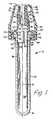
- Fig. 1 is a side elevational view in section of the blood microcollection assembly of the invention including a sample collection container having disposed on the top thereof a combination lancet and scoop collector with cap;
- Fig. 2 is a side elevational view of the assembly of Fig. 1 in the position after the taking of a blood sample wherein the cap has been moved to its locking position over the collector-lancet assembly fitted on top of the blood collection tube;
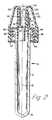
- Fig. 3 is a side elevational view in section of a further embodiment of blood collection-lancet assembly illustrating the invention; and
- Fig. 4 is a side elevational view in section of the assembly of Fig. 3 with the cap positioned in its final locking position on the scoop collector-lancet assembly of the invention.
- Referring to the drawings in which like reference characters refer to like parts throughout the several views thereof, Fig. 1 illustrates the invention as employed with a scoop collector similar to that taught in the above-noted United States Patent utilizing a vane or septum separating, in the blood collector on the top of the blood collection container, a blood collection passage from an air vent passage.
- Incorporated in the collector is a fixed lancet for forming the wound for collecting the sample to be collected by the collector.
- In Fig. 1, the
device 10 includes a blood microcollection container in the form of atube 12 having a closedend 16 and anopen end 14. The tube is a conventional blood microcollection tube and may be comprised of such materials as polyethylene, polypropylene or glass. Appropriately,tube 12 will be transparent or translucent to enable the nurse to know the quantity of blood collected. For the purpose of understanding the invention here and its position in use, reference is made to Fig. 5C in U.S. Patent 4,397,318. That is, the top of the device shown in the Figures is the front end, and the bottom is the left side as shown in the figures because the left side will be held so that it is the bottom of the device in use. - Positioned on the
top flange 52 oftube 12 is ablood collector 18 having ascoop arrangement 32 extending forwardly thereof. Thecollector assembly 18 is generally tubular in cross section with acentral bore 22 passing therethrough. Thescoop collector 18 is different from that taught and claimed in U.S. Patent 4,397,318 in that thefront end edge 31 of the vane orseptum 30 does not extend forwardly to form the upper edge of thescoop 32. The reason for thisshorter vane 30 will be described in further detail below. - The
collector 18 includes an annularintegral skirt 50, as shown in Fig. 1, which is spaced from the lower 28 and upper 26 walls forming thecentral bore 22 ofcollector 18. This spacing allows for anannular space 61 for receiving in press-fit engagement theannular flange 52 surrounding theopen end 14 oftube 12. Theskirt 50 includes an integralinternal abutment 63 which cooperates withflange 52 for maintainingcollector 18 on the top oftube 12.Annular skirt 50 also includes an annularouter abutment 48 which cooperates withcap 20 for holdingcap 20 locked oncollector 18 as will be described below. - Positioned in
end 57 ofwall 26 forming a part ofbore 22 islancet 125. As can be seen in Figs. 1 and 2,lancet 125 has one end embedded in the material ofholder 18 with the opposite sharp orpointed end 126 exposed for lancing the skin to obtain a blood sample. It will be appreciated in this connection, thatlancet 125 may be in several forms or configurations, including one with a straight wedge-shaped cutting edge. - Referring further to Fig. 1,
cap 20 includes an annularlower skirt 42, with an upper taperedportion 38 integral therewith. Whencap 20 is in place as shown in Fig. 1, the wall of the annular upper portion converges fromskirt 42 toward theaxis 13 of the assembly shown. The outer surface of thelower skirt portion 42 ofcap 20 includes a plurality of spacedribs 44, which provide for a better grip oncap 20, when it is to be removed from the assembly, as shown. The upper taperedportion 38 also includes a plurality ofannular ridges 40 which also serve to provide a gripping surface to thecap assembly 20. - The upper tapered
portion 38 ofcap 20 ends in atip 64 which connects to a central tubular internal well 60 ofcap 20. Well 60, as shown in Fig. 1, serves to fit internally inbore 22 ofcollector 18. Well 60 includes anannular abutment 56 which cooperates with thefront edge 57 ofupper wall 26 ofcollector 18 in the position ofcap 20 in Fig. 1. In this connection, the term "upper" as used herein is a designation for the right-hand portion ofcollector 18. The term "upper" as mentioned above is used to designate the upper side ofcollector 18 when the assembly is in use. That is, theair vent passage 24 will be positioned upwardly, while blood collection passage 35 will be positioned downwardly in the partially horizontal position of the collector assembly during collection of a blood sample, much in the same manner as the positioning shown in the above noted United States Patent 4,397,318. - As can be seen in Fig. 1,
skirt 42 ofcap 20 includes an integralinner abutment 46.Abutment 46, as shown in Fig. 1, cooperates withabutment 48 on collector 1 for engaging thecollector 18 and capping the assembly prior to use. That is, theabutment 48 serves as a stop for theabutment 46 with the latter being in press-fit engagement with the outer annular surface ofskirt 50 ofcollector 18. - Thus, a technician or nurse, wishing to collect a blood sample in the
assembly 10 of Fig. 1, receives the assembly with the parts thereof in the position shown in Fig. 1. The technician removescap 20 fromcollector 18, makes a skin puncture withlancet 125 and places thefront edge 62 ofscoop collector 32 adjacent the puncture. Blood flows alongsurface 33 ofbore 22 incollector 18, and passes from therear edge 34 of that surface into and along thesurface 36 oftube 12 to be collected in chamber 54 thereof. Once a proper quantity of a blood sample has been collected in chamber 54, the technician removes thefront edge 62 ofcollector 32 from the wound and places cap 20 oncollector 18 which in turn is still in place ontube 12. When the technician replacescap 20, the cap is press-fit ontocollector 18 to the degree wherein theannular abutment 46 onskirt 42 ofcap 20 rides over theabutment 48 ofcollector 18 to the position shown in Fig. 2. - Thus, the
abutment 46 slides down overabutment 48 and locks thecap 20 onto thecollector 18. With this arrangement therefor, thecollector 18, includinglancet 125, is completely covered and cannot be exposed to anyone. The entire assembly is conveyed to a lab for proper handling of a blood sample contained in chamber 54. At that time, the clinician in the lab may removecap 20 for obtaining access to the sample contained in chamber 54. When this happens, thecap 20 automatically removes thecollector assembly 18, together withlancet 125, as well, so that the entire combination of cap 20-collector 18-lancet 125 may be disposed of and any contaminated sample contained incollector 18 is removed from exposure to anyone handling the sample other than the appropriate handling which takes place in a clinical laboratory. - It should be noted here that in the locked position shown in Fig. 2, the annular integral well 60 of
cap 20 moves into thebore 22 ofcollector 18 to a point immediately adjacent thefront end 31 of septum orvein 30 for effectively sealing off thebore 22 ofcollector 18. In this connection, theannular abutment 56 on the outer surface of the annular integral internal well 60 ofcap 20 is press-fit against the wall ofbore 22 for a positive sealing engagement therewith. It should be noted further thatabutment 46 onannular skirt 42 ofcap 20 includes a taperedsurface 47 for ease of movement ofcap 20 into its locked position as shown in Fig. 2. That is, the taperedsurface 47 has the effect of camming theabutment 46 outwardly over theabutment 48 for cooperating locking engagement therewith. - A further embodiment of blood collection assembly is shown in Fig. 3. This collection assembly is similar to that shown and described in the Figs. 1 and 2 embodiment. However, in this embodiment, the
blood collector 72 does not include any centrally positioned vane orseptum 30 as shown in the Fig. 1 embodiment. Thecollector 72 includes acentral bore 80 defining apassage 82 through which a blood sample passes. Therefore, the skin is lanced with the sharp sterilefront end edge 135 oflancet 136. Then blood from the wound is taken byscoop 84 ofcollector 72, with thefront edge 86 thereof engaging the wound for receiving the blood which passes along thelower wall 76 ofbore 80 and leaves theend 78 thereof where it engages theinternal wall 36 of thecollector tube 12. In this embodiment, the internal tubular well 88 ofcap 74 is longer. Therefore, the bottom 92 of well 88 passes further into thepassage 82 ofcollector 72, as shown in Figs. 3 and 4. In the position of the assembly as shown in Fig. 4, thewall 92 extends substantially all the way into and fills up thepassage 82 ofbore 80. - The remaining parts in this embodiment are substantially the same as that in the Figs. 1 and 2 embodiment. That is,
collector 72 includes an annularintegral skirt 94 with an annularouter abutment 98 which cooperates with the annularinner abutment 96 ofskirt 100 ofcap 74.Cap 74 is in the same form ascap 20 of Fig. 1 in that it includes an annularlower skirt portion 100 with spacedribs 102 thereon, and taperedfront end wall 108 ending in thefront end edge 104.Tapered wall 108 includes a plurality of spacedannular abutment ridges 106 which serve together with theridges 102 to provide gripping surfaces on the outer surface ofcap 74 making it easier to grip to remove the entire collector-cap assembly so that the clinician in the laboratory can obtain a sample. - The
cap 74, in the same manner ascap 20, has a two-position arrangement with a final locking position as shown in Fig. 4, achieved after passage of the taperedsurface 97 overabutment 98 in a camming action. The annular internal well 88 ofcap 74 includes anannular abutment 90 which cooperates with thefront edge 85 of the upper wall portion ofcollector 72 in the position shown in the initially capped position of thecap 74 shown in Fig. 3. This annular abutment wedges into thebore 80 ofcollector 72, as shown in the final locked position ofcap 74 in Fig. 4. It should be understood, in this connection thatannular abutment 90 may be positioned at other locations along the length ofwell 88. Either embodiment of the invention here may include anintegral strap 112 oncap 74 which strap 112 is attached to aring 110 for attaching the cap totube 12 to prevent loss or misplacement thereof. Other ataching configurations, such as a U-shape partial ring may be used, as will be understood by practitioners-in-the-art. Also, either embodiment may include a thumb "roll" or flange 200 to facilitate removal of the assembly fromtube 12 by the use of the thumb pushing up on flange 200. - Preferably, the assembly of the invention will be comprised of a clear molded thermoplastic such as polyethylene, for example. Other materials which may be used, as will be appreciated by practitioners-in-the-art, include various thermoplastics such as polypropylene and polyvinylchloride. The cap may be comprised of Alathon 20-6064, a polyethylene formulation of DuPont, for example. Preferably, the microcollection container itself is comprised of a clear thermoplastic material, such as polypropylene, which has been properly treated to provide a hydrophillic internal surface for enhancing the flow of blood introduced therein. The internal surface of the container may also utilize a surface active agent such as a silicon coating.
- Whereas, as discussed above, a specific embodiment of microcollection container has been shown to be used in the assembly of the invention, it should be understood that it is within the purview of this invention that other forms of microcollection containers may be used configured with different cooperating locking arrangements with the associated collection assembly and cap of the invention. That is, the lancet may be oriented differently relative to the rest of the assembly. For example, it may be positioned to extend radially from the assembly. Moreover, other forms of collection assemblies may be used with the combined built-in form of lancet of the invention. In this connection, it should be noted that the collection assembly should be in a form where it serves as the "handle" for the lancet-collector combination.
- The arrangement here teaches a press-fit engagement with the container top relative to the collector, it is within the purview of the invention that a cooperating screw arrangement could be utilized. Also, the lancet may be incorporated into the snap-cap rather than the collector of the assembly herein. The point is, that the collector itself cannot be removed without the cap covering it and the associated lancet to protect the user from contamination from the time the sample is collected until such time as the lab technician removes the cap for otaining the sample contained in the container.
- While the forms of apparatus herein described constitute preferred embodients of the invention, it is to be understood that the invention is not limited to these precise forms of apparatus, and that changes may be made therein without departing from the scope of the invention which is defined in the appended claims.
Claims (8)
- A blood collection assembly comprisinga) a tube-shaped container (12) having a closed end (16) and an open end (14);b) a blood collector (18;72) mounted on said open end; said collector (18;72) including(1) a substantially tubular collector body having a tubular flow passage (22;82) therethrough;(2) said body extending from a puncture wound engaging front end surface (62;86) to a blood discharge rear end surface (34;78);(3) means (50;63) on said body for attaching said body to said open end of said container (12);(4) vent means (24;82) in said body for air displacement therethrough;c) a removable cap (20;100) mounted on said blood collector for closing the front end thereof and covering said lancet (125;136);characterized byd) a lancet (125;136) positioned in said collector (18;72) with the cutting edge (126;135) thereof positioned adjacent said front end surface (62) of said collector, the removable cap (20;100) covering said lancet ande) two-position cooperating locking means (48,46; 98,96) on said blood collector (18;72) and said cap (20;100) for removably holding said cap on said collector in a first position and for permanently locking said cap on said collector and lancet in a second position.
- The assembly of claim 1, further characterized bya) a vane (30) positioned in said tubular flow passage (22), said vane dividing said tubular flow passage into a blood flow passage (35) and said vent means (24).
- The assembly of claim 1 or 2, further characterized by said two-position cooperating locking means includinga) a first annular abutment (48;98) on said blood collector body, said first annular abutment extending outwardly from said body;b) a second annular abutment (46;96) on said cap (20;100), said second annular abutment extending inwardly from said cap, andc) a tapered surface on said second annular abutment (46;96) for camming said second abutment over said first abutment (48;98) into said permanent locking second position of said cap on said collector.
- The assembly of one of claims 1-3, further characterized bya) said cap including an integral centrally positioned well (60) coaxial with the axis of said cap (20); andb) said well (60) extending into said tubular flow passage (22) of said collector.
- The assembly of one of claims 1-4, further characterized by said means for attaching (50,63) includinga) a tubular skirt (50;94) on said collector (18;72) and integral therewith; andb) said skirt being coaxial with said tubular flow passage (22;82) and spaced therefrom;c) whereby the annular open end of said container (12) is received in press-fit engagement in said space (61) between said collector body and the skirt (50;94) thereof.
- The assembly of one of claims 1-5, further characterized bya) a plurality of spaced ribs (44;102) on the outer surface of said cap (20;100) for providing a gripping surface thereon.
- The assembly of one of claims 1-6, further characterized bya) an integral strap (112) connected to said cap (100);b) a ring (110) on the end of said strap opposite said cap; andc) said ring (110) or clamp for surrounding said tube-shaped container (70) for preventing loss of said cap.
- The assembly of one of claims 1-7, further characterized bya) the cutting edge (126;135) of said lancet (125;136) being positioned on the opposite side of the axis of said assembly from the said front end surface (62;86) of said collector.
Priority Applications (1)
| Application Number | Priority Date | Filing Date | Title |
|---|---|---|---|
| MYPI87002816AMY100104A (en) | 1985-01-25 | 1987-10-01 | Blood collection assembly |
Applications Claiming Priority (2)
| Application Number | Priority Date | Filing Date | Title |
|---|---|---|---|
| US06/695,120US4608997A (en) | 1985-01-25 | 1985-01-25 | Blood collection assembly |
| US695120 | 1991-05-03 |
Publications (3)
| Publication Number | Publication Date |
|---|---|
| EP0189118A2 EP0189118A2 (en) | 1986-07-30 |
| EP0189118A3 EP0189118A3 (en) | 1989-05-10 |
| EP0189118B1true EP0189118B1 (en) | 1991-10-30 |
Family
ID=24791659
Family Applications (1)
| Application Number | Title | Priority Date | Filing Date |
|---|---|---|---|
| EP86100493AExpired - LifetimeEP0189118B1 (en) | 1985-01-25 | 1986-01-16 | Blood collection assembly |
Country Status (11)
| Country | Link |
|---|---|
| US (1) | US4608997A (en) |
| EP (1) | EP0189118B1 (en) |
| JP (1) | JPS61176330A (en) |
| AU (1) | AU570175B2 (en) |
| DE (1) | DE3682213D1 (en) |
| DK (1) | DK168615B1 (en) |
| ES (1) | ES8705767A1 (en) |
| MX (1) | MX164213B (en) |
| MY (1) | MY100104A (en) |
| NZ (1) | NZ214907A (en) |
| ZA (1) | ZA86469B (en) |
Families Citing this family (81)
| Publication number | Priority date | Publication date | Assignee | Title |
|---|---|---|---|---|
| DE3541041A1 (en)* | 1985-11-19 | 1987-05-21 | Sarstedt Kunststoff | BLOOD COLLECTOR |
| US5224932A (en)* | 1988-09-27 | 1993-07-06 | Venivee, Inc. | System for intravenous administration of a plurality of medicaments and/or nutrients |
| US4920977A (en)* | 1988-10-25 | 1990-05-01 | Becton, Dickinson And Company | Blood collection assembly with lancet and microcollection tube |
| US5378431A (en)* | 1993-06-14 | 1995-01-03 | Becton, Dickinson And Company | Dual pathway clotting enhancer for blood collection tube |
| DE9418060U1 (en)* | 1994-11-11 | 1996-03-14 | SC - Sanguis Counting Kontrollblutherstellungs- und Vertriebs GmbH, 51588 Nümbrecht | Sample tube and end cap, especially for capillary blood collection |
| US6036924A (en) | 1997-12-04 | 2000-03-14 | Hewlett-Packard Company | Cassette of lancet cartridges for sampling blood |
| US6391005B1 (en) | 1998-03-30 | 2002-05-21 | Agilent Technologies, Inc. | Apparatus and method for penetration with shaft having a sensor for sensing penetration depth |
| US6195411B1 (en) | 1999-05-13 | 2001-02-27 | Photoelectron Corporation | Miniature x-ray source with flexible probe |
| JP4210782B2 (en)* | 1999-10-13 | 2009-01-21 | アークレイ株式会社 | Blood sampling position indicator |
| US8641644B2 (en) | 2000-11-21 | 2014-02-04 | Sanofi-Aventis Deutschland Gmbh | Blood testing apparatus having a rotatable cartridge with multiple lancing elements and testing means |
| US7344507B2 (en) | 2002-04-19 | 2008-03-18 | Pelikan Technologies, Inc. | Method and apparatus for lancet actuation |
| JP4209767B2 (en) | 2001-06-12 | 2009-01-14 | ペリカン テクノロジーズ インコーポレイテッド | Self-optimized cutting instrument with adaptive means for temporary changes in skin properties |
| US9795747B2 (en) | 2010-06-02 | 2017-10-24 | Sanofi-Aventis Deutschland Gmbh | Methods and apparatus for lancet actuation |
| WO2002101359A2 (en) | 2001-06-12 | 2002-12-19 | Pelikan Technologies, Inc. | Integrated blood sampling analysis system with multi-use sampling module |
| US7041068B2 (en) | 2001-06-12 | 2006-05-09 | Pelikan Technologies, Inc. | Sampling module device and method |
| US8337419B2 (en) | 2002-04-19 | 2012-12-25 | Sanofi-Aventis Deutschland Gmbh | Tissue penetration device |
| EP1395185B1 (en) | 2001-06-12 | 2010-10-27 | Pelikan Technologies Inc. | Electric lancet actuator |
| US9226699B2 (en) | 2002-04-19 | 2016-01-05 | Sanofi-Aventis Deutschland Gmbh | Body fluid sampling module with a continuous compression tissue interface surface |
| US7981056B2 (en) | 2002-04-19 | 2011-07-19 | Pelikan Technologies, Inc. | Methods and apparatus for lancet actuation |
| AU2002344825A1 (en) | 2001-06-12 | 2002-12-23 | Pelikan Technologies, Inc. | Method and apparatus for improving success rate of blood yield from a fingerstick |
| JP4272051B2 (en) | 2001-06-12 | 2009-06-03 | ペリカン テクノロジーズ インコーポレイテッド | Blood sampling apparatus and method |
| US7749174B2 (en) | 2001-06-12 | 2010-07-06 | Pelikan Technologies, Inc. | Method and apparatus for lancet launching device intergrated onto a blood-sampling cartridge |
| US9427532B2 (en) | 2001-06-12 | 2016-08-30 | Sanofi-Aventis Deutschland Gmbh | Tissue penetration device |
| US7344894B2 (en) | 2001-10-16 | 2008-03-18 | Agilent Technologies, Inc. | Thermal regulation of fluidic samples within a diagnostic cartridge |
| US7410468B2 (en) | 2002-04-19 | 2008-08-12 | Pelikan Technologies, Inc. | Method and apparatus for penetrating tissue |
| US7141058B2 (en) | 2002-04-19 | 2006-11-28 | Pelikan Technologies, Inc. | Method and apparatus for a body fluid sampling device using illumination |
| US9795334B2 (en) | 2002-04-19 | 2017-10-24 | Sanofi-Aventis Deutschland Gmbh | Method and apparatus for penetrating tissue |
| US7485128B2 (en) | 2002-04-19 | 2009-02-03 | Pelikan Technologies, Inc. | Method and apparatus for penetrating tissue |
| US7229458B2 (en) | 2002-04-19 | 2007-06-12 | Pelikan Technologies, Inc. | Method and apparatus for penetrating tissue |
| US7524293B2 (en) | 2002-04-19 | 2009-04-28 | Pelikan Technologies, Inc. | Method and apparatus for penetrating tissue |
| US7563232B2 (en) | 2002-04-19 | 2009-07-21 | Pelikan Technologies, Inc. | Method and apparatus for penetrating tissue |
| US8360992B2 (en) | 2002-04-19 | 2013-01-29 | Sanofi-Aventis Deutschland Gmbh | Method and apparatus for penetrating tissue |
| WO2003088824A2 (en) | 2002-04-19 | 2003-10-30 | Pelikan Technologies, Inc. | Device and method for variable speed lancet |
| US8221334B2 (en) | 2002-04-19 | 2012-07-17 | Sanofi-Aventis Deutschland Gmbh | Method and apparatus for penetrating tissue |
| US7491178B2 (en) | 2002-04-19 | 2009-02-17 | Pelikan Technologies, Inc. | Method and apparatus for penetrating tissue |
| US7717863B2 (en) | 2002-04-19 | 2010-05-18 | Pelikan Technologies, Inc. | Method and apparatus for penetrating tissue |
| US9248267B2 (en) | 2002-04-19 | 2016-02-02 | Sanofi-Aventis Deustchland Gmbh | Tissue penetration device |
| US7648468B2 (en) | 2002-04-19 | 2010-01-19 | Pelikon Technologies, Inc. | Method and apparatus for penetrating tissue |
| US7674232B2 (en) | 2002-04-19 | 2010-03-09 | Pelikan Technologies, Inc. | Method and apparatus for penetrating tissue |
| US7331931B2 (en) | 2002-04-19 | 2008-02-19 | Pelikan Technologies, Inc. | Method and apparatus for penetrating tissue |
| US7371247B2 (en) | 2002-04-19 | 2008-05-13 | Pelikan Technologies, Inc | Method and apparatus for penetrating tissue |
| US8267870B2 (en) | 2002-04-19 | 2012-09-18 | Sanofi-Aventis Deutschland Gmbh | Method and apparatus for body fluid sampling with hybrid actuation |
| US7708701B2 (en) | 2002-04-19 | 2010-05-04 | Pelikan Technologies, Inc. | Method and apparatus for a multi-use body fluid sampling device |
| US7909778B2 (en) | 2002-04-19 | 2011-03-22 | Pelikan Technologies, Inc. | Method and apparatus for penetrating tissue |
| US7244265B2 (en) | 2002-04-19 | 2007-07-17 | Pelikan Technologies, Inc. | Method and apparatus for penetrating tissue |
| US8702624B2 (en) | 2006-09-29 | 2014-04-22 | Sanofi-Aventis Deutschland Gmbh | Analyte measurement device with a single shot actuator |
| US7291117B2 (en) | 2002-04-19 | 2007-11-06 | Pelikan Technologies, Inc. | Method and apparatus for penetrating tissue |
| US7892183B2 (en) | 2002-04-19 | 2011-02-22 | Pelikan Technologies, Inc. | Method and apparatus for body fluid sampling and analyte sensing |
| US7547287B2 (en) | 2002-04-19 | 2009-06-16 | Pelikan Technologies, Inc. | Method and apparatus for penetrating tissue |
| US7297122B2 (en) | 2002-04-19 | 2007-11-20 | Pelikan Technologies, Inc. | Method and apparatus for penetrating tissue |
| US7374544B2 (en) | 2002-04-19 | 2008-05-20 | Pelikan Technologies, Inc. | Method and apparatus for penetrating tissue |
| US7232451B2 (en) | 2002-04-19 | 2007-06-19 | Pelikan Technologies, Inc. | Method and apparatus for penetrating tissue |
| US8372016B2 (en) | 2002-04-19 | 2013-02-12 | Sanofi-Aventis Deutschland Gmbh | Method and apparatus for body fluid sampling and analyte sensing |
| US7901362B2 (en) | 2002-04-19 | 2011-03-08 | Pelikan Technologies, Inc. | Method and apparatus for penetrating tissue |
| US9314194B2 (en) | 2002-04-19 | 2016-04-19 | Sanofi-Aventis Deutschland Gmbh | Tissue penetration device |
| US7976476B2 (en) | 2002-04-19 | 2011-07-12 | Pelikan Technologies, Inc. | Device and method for variable speed lancet |
| US8579831B2 (en) | 2002-04-19 | 2013-11-12 | Sanofi-Aventis Deutschland Gmbh | Method and apparatus for penetrating tissue |
| US8784335B2 (en) | 2002-04-19 | 2014-07-22 | Sanofi-Aventis Deutschland Gmbh | Body fluid sampling device with a capacitive sensor |
| US7572237B2 (en) | 2002-11-06 | 2009-08-11 | Abbott Diabetes Care Inc. | Automatic biological analyte testing meter with integrated lancing device and methods of use |
| US8574895B2 (en) | 2002-12-30 | 2013-11-05 | Sanofi-Aventis Deutschland Gmbh | Method and apparatus using optical techniques to measure analyte levels |
| DE602004028463D1 (en) | 2003-05-30 | 2010-09-16 | Pelikan Technologies Inc | METHOD AND DEVICE FOR INJECTING LIQUID |
| US7850621B2 (en) | 2003-06-06 | 2010-12-14 | Pelikan Technologies, Inc. | Method and apparatus for body fluid sampling and analyte sensing |
| WO2006001797A1 (en) | 2004-06-14 | 2006-01-05 | Pelikan Technologies, Inc. | Low pain penetrating |
| EP1635700B1 (en) | 2003-06-13 | 2016-03-09 | Sanofi-Aventis Deutschland GmbH | Apparatus for a point of care device |
| US8282576B2 (en) | 2003-09-29 | 2012-10-09 | Sanofi-Aventis Deutschland Gmbh | Method and apparatus for an improved sample capture device |
| EP1680014A4 (en) | 2003-10-14 | 2009-01-21 | Pelikan Technologies Inc | METHOD AND DEVICE FOR A VARIABLE USER INTERFACE |
| US8668656B2 (en) | 2003-12-31 | 2014-03-11 | Sanofi-Aventis Deutschland Gmbh | Method and apparatus for improving fluidic flow and sample capture |
| US7822454B1 (en) | 2005-01-03 | 2010-10-26 | Pelikan Technologies, Inc. | Fluid sampling device with improved analyte detecting member configuration |
| US20050178218A1 (en)* | 2004-01-28 | 2005-08-18 | Jean Montagu | Micro-volume blood sampling device |
| WO2006011062A2 (en) | 2004-05-20 | 2006-02-02 | Albatros Technologies Gmbh & Co. Kg | Printable hydrogel for biosensors |
| WO2005120365A1 (en) | 2004-06-03 | 2005-12-22 | Pelikan Technologies, Inc. | Method and apparatus for a fluid sampling device |
| US9775553B2 (en) | 2004-06-03 | 2017-10-03 | Sanofi-Aventis Deutschland Gmbh | Method and apparatus for a fluid sampling device |
| US8652831B2 (en) | 2004-12-30 | 2014-02-18 | Sanofi-Aventis Deutschland Gmbh | Method and apparatus for analyte measurement test time |
| JP4956743B2 (en)* | 2005-11-10 | 2012-06-20 | 株式会社東京ドリームワークス | Coated uncured stucco sheet |
| WO2007089930A2 (en)* | 2006-01-31 | 2007-08-09 | Facet Technologies, Llc | Lancet with cap-removal guidance |
| EP2265324B1 (en) | 2008-04-11 | 2015-01-28 | Sanofi-Aventis Deutschland GmbH | Integrated analyte measurement system |
| US9375169B2 (en) | 2009-01-30 | 2016-06-28 | Sanofi-Aventis Deutschland Gmbh | Cam drive for managing disposable penetrating member actions with a single motor and motor and control system |
| US8965476B2 (en) | 2010-04-16 | 2015-02-24 | Sanofi-Aventis Deutschland Gmbh | Tissue penetration device |
| KR101251890B1 (en)* | 2011-03-31 | 2013-04-08 | (주)아이소텍 | Portable laser lancing device using dual safety device |
| US20140296743A1 (en)* | 2013-04-01 | 2014-10-02 | Kee Jung Choi | Portable laser blood sampling device having dual safety device and disposable cap used therein |
| NL2019531B1 (en)* | 2017-09-12 | 2019-03-27 | Labonovum B V | Collection device for a substantially liquid biological specimen |
Citations (1)
| Publication number | Priority date | Publication date | Assignee | Title |
|---|---|---|---|---|
| WO1983000281A1 (en)* | 1981-07-27 | 1983-02-03 | American Hospital Supply Corp | Ventable sample collection device |
Family Cites Families (19)
| Publication number | Priority date | Publication date | Assignee | Title |
|---|---|---|---|---|
| US2705955A (en)* | 1952-12-18 | 1955-04-12 | Baxter Laboratories Inc | Parenteral administration set and air inlet closure structure for use therein |
| US2941531A (en)* | 1958-08-26 | 1960-06-21 | Roehr Products Company Inc | Hypodermic needle assembly |
| NL293244A (en)* | 1962-05-29 | |||
| US3288318A (en)* | 1964-11-24 | 1966-11-29 | John D Corbin | Flexible plastic vial |
| US3381813A (en)* | 1965-09-07 | 1968-05-07 | Pharmaseal Lab | Hypodermic needle and protector therefor |
| CH522395A (en)* | 1968-07-26 | 1972-05-15 | Micromedic Systems Inc | Test tube intended for percutaneous and digital blood sampling |
| FR2040666A5 (en)* | 1969-04-18 | 1971-01-22 | Astra De Bouchage | Test tubes for chemical or biological - reactions |
| US3753432A (en)* | 1971-03-10 | 1973-08-21 | L Guerra | Hypodermic syringe for blood tests |
| FR2187361B1 (en)* | 1972-06-14 | 1975-06-13 | Cooper France Sa | |
| US3848780A (en)* | 1974-02-13 | 1974-11-19 | Stull Engraving Co | Safety cap |
| US4024857A (en)* | 1974-12-23 | 1977-05-24 | Becton, Dickinson And Company | Micro blood collection device |
| US4215700A (en)* | 1978-08-25 | 1980-08-05 | Sherwood Medical Industries Inc. | Blood collection device |
| BR7808764A (en)* | 1978-11-28 | 1981-06-30 | Dematex Dev & Invest | TUBE AND STOPPER FOR BLOOD SAMPLING SYSTEMS |
| US4250893A (en)* | 1979-02-21 | 1981-02-17 | American Hospital Supply Corporation | Sample collection device |
| US4280631A (en)* | 1980-03-10 | 1981-07-28 | Owens-Illinois, Inc. | Safety closure and container with snap cap liner |
| US4360016A (en)* | 1980-07-01 | 1982-11-23 | Transidyne General Corp. | Blood collecting device |
| US4397318A (en)* | 1981-08-10 | 1983-08-09 | Becton Dickinson And Company | Blood collector for microcollection container |
| US4534763A (en)* | 1983-09-14 | 1985-08-13 | Gettig William A | Hypodermic cartridge |
| US4548332A (en)* | 1984-12-31 | 1985-10-22 | Neat Benjamin C | Tamperproof plastic container |
- 1985
- 1985-01-25USUS06/695,120patent/US4608997A/ennot_activeExpired - Lifetime
- 1986
- 1986-01-15AUAU52264/86Apatent/AU570175B2/ennot_activeCeased
- 1986-01-16DEDE8686100493Tpatent/DE3682213D1/ennot_activeExpired - Fee Related
- 1986-01-16EPEP86100493Apatent/EP0189118B1/ennot_activeExpired - Lifetime
- 1986-01-21MXMX1293Apatent/MX164213B/enunknown
- 1986-01-22ZAZA86469Apatent/ZA86469B/enunknown
- 1986-01-23NZNZ214907Apatent/NZ214907A/enunknown
- 1986-01-24ESES551213Apatent/ES8705767A1/ennot_activeExpired
- 1986-01-24DKDK038386Apatent/DK168615B1/ennot_activeIP Right Cessation
- 1986-01-24JPJP61013618Apatent/JPS61176330A/enactiveGranted
- 1987
- 1987-10-01MYMYPI87002816Apatent/MY100104A/enunknown
Patent Citations (1)
| Publication number | Priority date | Publication date | Assignee | Title |
|---|---|---|---|---|
| WO1983000281A1 (en)* | 1981-07-27 | 1983-02-03 | American Hospital Supply Corp | Ventable sample collection device |
Also Published As
| Publication number | Publication date |
|---|---|
| DK168615B1 (en) | 1994-05-09 |
| EP0189118A3 (en) | 1989-05-10 |
| ZA86469B (en) | 1986-09-24 |
| US4608997A (en) | 1986-09-02 |
| JPS61176330A (en) | 1986-08-08 |
| EP0189118A2 (en) | 1986-07-30 |
| AU5226486A (en) | 1986-07-31 |
| MX164213B (en) | 1992-07-27 |
| JPH039736B2 (en) | 1991-02-12 |
| DE3682213D1 (en) | 1991-12-05 |
| NZ214907A (en) | 1989-07-27 |
| DK38386A (en) | 1986-07-26 |
| DK38386D0 (en) | 1986-01-24 |
| MY100104A (en) | 1989-10-10 |
| ES551213A0 (en) | 1987-05-16 |
| AU570175B2 (en) | 1988-03-03 |
| ES8705767A1 (en) | 1987-05-16 |
Similar Documents
| Publication | Publication Date | Title |
|---|---|---|
| EP0189118B1 (en) | Blood collection assembly | |
| US4920977A (en) | Blood collection assembly with lancet and microcollection tube | |
| EP0366826B1 (en) | Swab retaining vial cap | |
| CA2067691C (en) | Stopper-shield combination closure | |
| EP0129029B1 (en) | Low contamination closure for blood collection tubes | |
| EP0627197B1 (en) | Collection assembly | |
| EP0189153B1 (en) | Blood collection assembly | |
| US5360423A (en) | Means for safe collection and transfer of body fluids | |
| JP2740318B2 (en) | Blood collection cylinder with needle ejector | |
| US20050010189A1 (en) | Body fluid collection apparatus | |
| JP2003527897A (en) | Blood lancet with hygienic tip protection | |
| EP0595507B1 (en) | Needle stopper and needle removal device | |
| JP2008532661A (en) | Needlestick injury safety device | |
| EP0321032B1 (en) | Single-use devices for collecting and holding blood samples | |
| US5624404A (en) | Hand held phlebotomy protection device | |
| EP1487369B1 (en) | Biological fluid sampling apparatus | |
| US20250017501A1 (en) | Collector Accessory for Small Volume Collection Containers and Related Sample Collection Methods | |
| US20250302350A1 (en) | Blood Collection Device with Front-End Automation Features | |
| EP4175557B1 (en) | Fluid sample collection container with cap and removal tool for finger grip luer adapter | |
| NZ214710A (en) | Blood collection assembly: cap removably held or permanently locked to blood collector |
Legal Events
| Date | Code | Title | Description |
|---|---|---|---|
| PUAI | Public reference made under article 153(3) epc to a published international application that has entered the european phase | Free format text:ORIGINAL CODE: 0009012 | |
| AK | Designated contracting states | Kind code of ref document:A2 Designated state(s):BE CH DE FR GB IT LI NL SE | |
| PUAL | Search report despatched | Free format text:ORIGINAL CODE: 0009013 | |
| AK | Designated contracting states | Kind code of ref document:A3 Designated state(s):BE CH DE FR GB IT LI NL SE | |
| 17P | Request for examination filed | Effective date:19891021 | |
| 17Q | First examination report despatched | Effective date:19900322 | |
| GRAA | (expected) grant | Free format text:ORIGINAL CODE: 0009210 | |
| AK | Designated contracting states | Kind code of ref document:B1 Designated state(s):BE CH DE FR GB IT LI NL SE | |
| ITF | It: translation for a ep patent filed | ||
| REF | Corresponds to: | Ref document number:3682213 Country of ref document:DE Date of ref document:19911205 | |
| ET | Fr: translation filed | ||
| PLBE | No opposition filed within time limit | Free format text:ORIGINAL CODE: 0009261 | |
| STAA | Information on the status of an ep patent application or granted ep patent | Free format text:STATUS: NO OPPOSITION FILED WITHIN TIME LIMIT | |
| 26N | No opposition filed | ||
| EAL | Se: european patent in force in sweden | Ref document number:86100493.5 | |
| PGFP | Annual fee paid to national office [announced via postgrant information from national office to epo] | Ref country code:SE Payment date:19970115 Year of fee payment:12 | |
| PGFP | Annual fee paid to national office [announced via postgrant information from national office to epo] | Ref country code:CH Payment date:19970121 Year of fee payment:12 | |
| PGFP | Annual fee paid to national office [announced via postgrant information from national office to epo] | Ref country code:NL Payment date:19970130 Year of fee payment:12 | |
| PGFP | Annual fee paid to national office [announced via postgrant information from national office to epo] | Ref country code:BE Payment date:19970318 Year of fee payment:12 | |
| PG25 | Lapsed in a contracting state [announced via postgrant information from national office to epo] | Ref country code:SE Free format text:LAPSE BECAUSE OF NON-PAYMENT OF DUE FEES Effective date:19980117 | |
| PG25 | Lapsed in a contracting state [announced via postgrant information from national office to epo] | Ref country code:LI Free format text:LAPSE BECAUSE OF NON-PAYMENT OF DUE FEES Effective date:19980131 Ref country code:CH Free format text:LAPSE BECAUSE OF NON-PAYMENT OF DUE FEES Effective date:19980131 Ref country code:BE Free format text:LAPSE BECAUSE OF NON-PAYMENT OF DUE FEES Effective date:19980131 | |
| BERE | Be: lapsed | Owner name:BECTON DICKINSON AND CY Effective date:19980131 | |
| PG25 | Lapsed in a contracting state [announced via postgrant information from national office to epo] | Ref country code:NL Free format text:LAPSE BECAUSE OF NON-PAYMENT OF DUE FEES Effective date:19980801 | |
| REG | Reference to a national code | Ref country code:CH Ref legal event code:PL | |
| NLV4 | Nl: lapsed or anulled due to non-payment of the annual fee | Effective date:19980801 | |
| EUG | Se: european patent has lapsed | Ref document number:86100493.5 | |
| PGFP | Annual fee paid to national office [announced via postgrant information from national office to epo] | Ref country code:FR Payment date:19990111 Year of fee payment:14 | |
| PGFP | Annual fee paid to national office [announced via postgrant information from national office to epo] | Ref country code:GB Payment date:19990121 Year of fee payment:14 | |
| PGFP | Annual fee paid to national office [announced via postgrant information from national office to epo] | Ref country code:DE Payment date:19990125 Year of fee payment:14 | |
| PG25 | Lapsed in a contracting state [announced via postgrant information from national office to epo] | Ref country code:GB Free format text:LAPSE BECAUSE OF NON-PAYMENT OF DUE FEES Effective date:20000116 | |
| GBPC | Gb: european patent ceased through non-payment of renewal fee | Effective date:20000116 | |
| PG25 | Lapsed in a contracting state [announced via postgrant information from national office to epo] | Ref country code:FR Free format text:LAPSE BECAUSE OF NON-PAYMENT OF DUE FEES Effective date:20000929 | |
| PG25 | Lapsed in a contracting state [announced via postgrant information from national office to epo] | Ref country code:DE Free format text:LAPSE BECAUSE OF NON-PAYMENT OF DUE FEES Effective date:20001101 | |
| REG | Reference to a national code | Ref country code:FR Ref legal event code:ST | |
| PG25 | Lapsed in a contracting state [announced via postgrant information from national office to epo] | Ref country code:IT Free format text:LAPSE BECAUSE OF NON-PAYMENT OF DUE FEES;WARNING: LAPSES OF ITALIAN PATENTS WITH EFFECTIVE DATE BEFORE 2007 MAY HAVE OCCURRED AT ANY TIME BEFORE 2007. THE CORRECT EFFECTIVE DATE MAY BE DIFFERENT FROM THE ONE RECORDED. Effective date:20050116 |