EP0186333B1 - Method and apparatus for detecting surge in centrifugal compressors driven by electric motors - Google Patents
Method and apparatus for detecting surge in centrifugal compressors driven by electric motorsDownload PDFInfo
- Publication number
- EP0186333B1 EP0186333B1EP85308684AEP85308684AEP0186333B1EP 0186333 B1EP0186333 B1EP 0186333B1EP 85308684 AEP85308684 AEP 85308684AEP 85308684 AEP85308684 AEP 85308684AEP 0186333 B1EP0186333 B1EP 0186333B1
- Authority
- EP
- European Patent Office
- Prior art keywords
- signal
- compressor
- pressure
- threshold
- motor current
- Prior art date
- Legal status (The legal status is an assumption and is not a legal conclusion. Google has not performed a legal analysis and makes no representation as to the accuracy of the status listed.)
- Expired
Links
Images


Classifications
- F—MECHANICAL ENGINEERING; LIGHTING; HEATING; WEAPONS; BLASTING
- F04—POSITIVE - DISPLACEMENT MACHINES FOR LIQUIDS; PUMPS FOR LIQUIDS OR ELASTIC FLUIDS
- F04D—NON-POSITIVE-DISPLACEMENT PUMPS
- F04D27/00—Control, e.g. regulation, of pumps, pumping installations or pumping systems specially adapted for elastic fluids
- F04D27/001—Testing thereof; Determination or simulation of flow characteristics; Stall or surge detection, e.g. condition monitoring
- F—MECHANICAL ENGINEERING; LIGHTING; HEATING; WEAPONS; BLASTING
- F04—POSITIVE - DISPLACEMENT MACHINES FOR LIQUIDS; PUMPS FOR LIQUIDS OR ELASTIC FLUIDS
- F04D—NON-POSITIVE-DISPLACEMENT PUMPS
- F04D27/00—Control, e.g. regulation, of pumps, pumping installations or pumping systems specially adapted for elastic fluids
- F04D27/02—Surge control
- F04D27/0284—Conjoint control of two or more different functions
- F—MECHANICAL ENGINEERING; LIGHTING; HEATING; WEAPONS; BLASTING
- F25—REFRIGERATION OR COOLING; COMBINED HEATING AND REFRIGERATION SYSTEMS; HEAT PUMP SYSTEMS; MANUFACTURE OR STORAGE OF ICE; LIQUEFACTION SOLIDIFICATION OF GASES
- F25B—REFRIGERATION MACHINES, PLANTS OR SYSTEMS; COMBINED HEATING AND REFRIGERATION SYSTEMS; HEAT PUMP SYSTEMS
- F25B1/00—Compression machines, plants or systems with non-reversible cycle
- F25B1/04—Compression machines, plants or systems with non-reversible cycle with compressor of rotary type
- F25B1/053—Compression machines, plants or systems with non-reversible cycle with compressor of rotary type of turbine type
- H—ELECTRICITY
- H02—GENERATION; CONVERSION OR DISTRIBUTION OF ELECTRIC POWER
- H02H—EMERGENCY PROTECTIVE CIRCUIT ARRANGEMENTS
- H02H3/00—Emergency protective circuit arrangements for automatic disconnection directly responsive to an undesired change from normal electric working condition with or without subsequent reconnection ; integrated protection
- H02H3/44—Emergency protective circuit arrangements for automatic disconnection directly responsive to an undesired change from normal electric working condition with or without subsequent reconnection ; integrated protection responsive to the rate of change of electrical quantities
- H—ELECTRICITY
- H02—GENERATION; CONVERSION OR DISTRIBUTION OF ELECTRIC POWER
- H02H—EMERGENCY PROTECTIVE CIRCUIT ARRANGEMENTS
- H02H7/00—Emergency protective circuit arrangements specially adapted for specific types of electric machines or apparatus or for sectionalised protection of cable or line systems, and effecting automatic switching in the event of an undesired change from normal working conditions
- H02H7/08—Emergency protective circuit arrangements specially adapted for specific types of electric machines or apparatus or for sectionalised protection of cable or line systems, and effecting automatic switching in the event of an undesired change from normal working conditions for dynamo-electric motors
- H02H7/085—Emergency protective circuit arrangements specially adapted for specific types of electric machines or apparatus or for sectionalised protection of cable or line systems, and effecting automatic switching in the event of an undesired change from normal working conditions for dynamo-electric motors against excessive load
- H02H7/0854—Emergency protective circuit arrangements specially adapted for specific types of electric machines or apparatus or for sectionalised protection of cable or line systems, and effecting automatic switching in the event of an undesired change from normal working conditions for dynamo-electric motors against excessive load responsive to rate of change of current, couple or speed, e.g. anti-kickback protection
Definitions
- This inventionrelates generally to surge detection devices and more particularly, it relates to a method and apparatus for detecting surge in a compressor of a compressor-driven system.
- the inventionis susceptible of widely diverse use and may be applied to any system having equipment driven by a compressor, such as in a chemical process, pump and the like.
- surge or surgingis an unstable condition that may occur when centrifugal compressors are operated at light loads and high pressure ratios. It is a transient phenomenon which is characterized by high frequency oscillations in pressures and flow and in some cases, there may even be a complete flow reversal through the compressor. Such continuous surging causes excessive vibrations in both the rotating and stationary components of the compressor, which may cause permanent damage thereto.
- surge detection devices of the prior artrequired measurements of the compressor head and suction flow, and surge was avoided by opening a bypass valve.
- US-A 4 259 845discloses apparatus and a method in accordance with the prior art portion of claims 1 and 8 respectively.
- the present inventionincludes a first bandpass digital filter for generating a signal representative of the rate of change of the pressure developed across the compressor and a second bandpass digital filter for generating a signal representative of the rate of change of the RMS current being drawn by the compressor drive motor.
- the present inventionhas numerous applications in other fields and apparatus since the invention pertains to a method and apparatus for detecting surge in a compressor of a compressor-driven system.
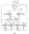
- FIG. 1in block diagram form a surge detection apparatus 10 of the present invention for use in a refrigeration or cooling system having a centrifugal compressor driven by an electric motor.
- EP-A 0 186 332for a specific illustration and explanation of the details of one such refrigeration system adapted to utilize the surge detection apparatus to be disclosed herein.
- a self-optimizing capacity control systemis shown for inverter-driven centrifugal compressor based water chillers wherein adjustable inlet guide vanes and compressor speed are both automatically regulated in response to a continually updated «learned» chiller surge surface so as to realize minimum overall chiller energy consumption.
- the control systemincludes a microprocessor for initiating a «learning» mode in which the compressor motor speed is continually decreased incrementally and the pre-rotational guide vanes are moved to a more open position until an operating point is found where the compressor is surging.
- the microprocessordetermines whether the compressor is surging in response to surge detection signals which may be generated by the surge detection apparatus of the present invention.
- the surge detection apparatus 10is depicted in Figure 1 in connection with a simplified version of a refrigeration system.
- the refrigeration systemincludes a centrifugal compressor 12, a condenser 14, an expansion device 16 and an evaporator 18, all being interconnected in series to form a conventional closed refrigeration circuit.
- Refrigerant gasis compressed in the compressor 12 and the compressed gas is delivered to the condenser 14 where a cooling medium, such as water from a cooling tower, causes the compressed gas to condense to a liquid refrigerant.
- the liquid refrigerantexpands as it is passed through the expansion device 16 to the evaporator 18.
- the capacity of the compressor 12is adjusted by regulating the flow rate of the refrigerant through the refrigeration system to vary its capacity.
- the surge detection apparatus 10includes motor current sensing means formed of a current transformer 24 which is connected to one phase line 26 of a three-input power source connections for driving a three-phase AC induction motor 20 for measuring the current flowing therein.
- the AC output voltage from the current transformer 24is converted to a D.C. voltage signal by a conventional full-wave bridge rectifer 28 and a load resistor 30.
- a first pressure transducer 32is placed in the condenser 14 to produce a signal which is a function of either the absolute or gauge pressure in the condenser 14.
- a second pressure transducer 34is placed in the evaporator 18 for producing a signal which is a function of either the absolute or gauge pressure in the evaporator 18. It should be understood by those skilled in the art that the transducers 32 and 34 could be located in the respective discharge line and suction line of the compressor 12.
- the D. C. output voltage from the load resistor 30is fed to a first low-pass filter circuit 36.
- the output of the first pressure transducer 32is fed to a second low-pass filter circuit 38, and the output of the second pressure transducer 34 is fed to a third low-pass filter circuit 40.
- the function of these low-pass filtersis to eliminate high frequency harmonics which may cause distortion.
- the «cut-off» or «break-frequency» of these filtersare typically selected to be equal to one-half of the frequency at which the measured or sensed voltage are sampled. Since it is desirable to use a sample frequency of two hz in the present invention, the filters are designed with a «cut-off» frequency of one hz.
- the output signal of the filter 36 representative of the motor current on line 42is connected to a multiplexer and A/D converter 44.
- the output signal of the filter 38 representative of the condenser pressure on line 46 and the output signal of the filter 40 representative of the evaporator pressure on line 48are also coupled to the multiplexer and A/D converter 44.
- a differential pressure function block 50receives as inputs the condenser and evaporator pressure signals via respective line 52, 54 and generates a differential signal on its output line 56.
- the block 50subtracts the evaporator pressure signal on line 54 from the condenser pressure signal on line 52.
- a first bandpass digital filter 58is connected to the output line 56 for producing a filtered rate of change of differential pressure signal on line 60 which is referred to as a «DIFFPFILT» signal.
- a second bandpass digital filter 61has its input connected to the motor current signal on line 62 for producing a filtered rate of change of motor current signal on line 63 which is referred to as a «MAMPSFILT» signal.
- a low-pass digital filter 64has its input connected to the motor current signal via line 66 for producing a RMS motor current value being drawn by the induction motor 20.
- a trigger threshold block 68calculates a filtered current threshold signal designated as a «MAMPSREF» signal on line 70 and a filtered differential pressure threshold signal designated as a «DIFFPREF» signal on line 72.
- the surge detection thresholdsare based on the filtered current and filtered differential pressure spikes or peaks which have been measured and stored in a storage block 74 during an induced light load surge when the surge detection apparatus is initially calibrated.
- the stored trigger thresholds MAMPSREF 0 and DIFFPREF 0are selected to be approximately thirty to fifty percent less than the peaks which are _ actually measured during the induced surge.
- the motor current and differential pressure thresholds MAMPSREF 0 and DIFFPREF 0increase by fifty percent over the range of RMS motor current shown on the abscissa in the curve portion A. Further, the motor current and differential pressure thresholds increase by another fifty percent in the curve portion B.
- the curve of Figure 3is generated by a full load motor current functional block 76 (Fig. 1) which is fed into the trigger threshold block 68 for adjusting the threshold depending upon the compressor load. It should be understood that the full rated current must be determined for each application and must be pre-set when the surge detection apparatus is installed.
- a five-second delay timer 78is connected to the output of the low-pass digital filter 64 so as to delay filtered RMS motor current by five seconds.
- the trigger thresholdswill be based upon the steady-state current being drawn by the motor immediately prior to the instant that surge occurs. With this delay, the thresholds will not be affected by the sudden five to ten percent reduction in the RMS motor current which occurs at surge.
- Figure 4 (a)there is shown a typical sensed or measured motor current signal which appears during surge on the line 42 from the low-passe filter 36.
- Figure 4(b)depicts a typical measured differential pressure signal during surge which appears on line 56 from the functional block 50.
- Figure 4(c)illustrates a typical bandpass filtered motor current signal found on line 63 from the bandpass filter 61.
- Figure 4 (d)there is illustrated a typical bandpass filtered differential pressure signal found on line 60 from the bandpass filter 58.
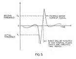
- FIG. 5 of the drawingsthere is illustrated graphically when a disturbance is to be interpreted as a valid surge.
- the first requirementis that both the filtered motor signal «MAMPSFILT» from the bandpass filter 61 and the filtered differential pressure signal «DIFFPFILT» from the bandpass filter 58 must exceed trigger thresholds MAMPSFILT and DIFFPFILT. Once both trigger thresholds are exceeded, an interval timer is activated.
- the second requirementis that after the filtered motor current signal exceeds the initial threshold T1 it must reverse, pass through zero, continue in the opposite direction and exceed a second threshold T2.
- a waveform of a filtered motor current signalis depicted in Figure 5 where the amplitude is plotted along the ordinate and the time is plotted along the abscissa.
- the initial and second thresholdsare shown adjacent the ordinate axis.
- the third requirementis that the second or reversed filtered motor current signal must exceed the second threshold T2 before the interval timer, which was activated when the first requirement was satisfied, resets or expires.
- This reset intervalis a pre-specified time period which is selected based upon the size of compressor. However, a reset time interval of three seconds is typically used in refrigeration applications.
- the details of a computing device such as a microprocessor 73 required to perform the function just described with respect to the operation of Figure 5are shown in Figure 2 in a flow chart fashion.
- the microprocessor 73receives as input signals the filtered motor current signal «MAMPSFILT» on line 63, the filtered differential pressure signal «DIFFPFILT» on line 60, the filtered current threshold «MAMPSREF» on line 70, and the filtered differential pressure threshold signal «DIFFPREF» on line 72 from the surge detection apparatus 10.
- the surge identification processis initiated by a start block 80 which causes the reading of the input signals on the respective lines 60, 63, 70, and 72.
- a logic or decision block 82compares the absolute value of the filtered motor current signal «MAMPSFILT» against the filtered current threshold signal «MAMPSREF».
- a logic or decision block 84compares the absolute value of the filtered differential pressure signal «DIFFPFILT» against the filtered differential pressure signal «DIFFPREF». If either threshold is not exceeded, the surge identification process is returned to the start block 80 in order to read the new input signals.
- a timer block 86is activated where the reset interval has been selected, in this instance, for a period of three seconds.
- the polarity of the first filtered motor current signalis determined by a block 88 which assigns a negative or positive sign to the second trigger threshold. If the polarity of the first filtered motor current signal is positive, then logic block 90 compares continuously the second filtered motor current signal against the second trigger threshold which is assigned a negative polarity.
- a logic block 92determines when the three-second time interval has been exceeded. If the second threshold has been exceeded within this time interval, a valid surge is indicated by a surge identification block 94. Otherwise, the surge identification process is returned to the start block 80.
- a logic block 96compares continuously the second filtered motor current signal against the second trigger threshold which is assigned a positive polarity.
- a logic block 98determines when the three-second time interval has been exceeded. If the second threshold has been exceeded within this time interval, a valid surge is indicated by a surge identification block 100. Otherwise, the surge detection apparatus is returned to the start block 80.
- the present inventionprovides a surge detection apparatus for use in refrigeration systems having a centrifugal compressor driven by an electric motor which is based upon the rate of change of pressure developed across the compressor and the rate of change of current drawn by the compressor drive motor. Signals representative of the rate of change of the pressure developed across the compressor and the rate of change of the RMS motor current are generated by bandpass digital filters. A microprocessor responsive to these signals are provided for indication when a valid surge is occurring in the compressor.
Landscapes
- Engineering & Computer Science (AREA)
- Mechanical Engineering (AREA)
- General Engineering & Computer Science (AREA)
- Physics & Mathematics (AREA)
- Thermal Sciences (AREA)
- Control Of Positive-Displacement Air Blowers (AREA)
- Testing Of Devices, Machine Parts, Or Other Structures Thereof (AREA)
Description
- This invention relates generally to surge detection devices and more particularly, it relates to a method and apparatus for detecting surge in a compressor of a compressor-driven system.
- The invention is susceptible of widely diverse use and may be applied to any system having equipment driven by a compressor, such as in a chemical process, pump and the like.
- A prior art search directed to the subject matter of this application in the U.S. Patent and Trademark Office revealed the following U.S. Letters Patent:

- As is generally known, surge or surging is an unstable condition that may occur when centrifugal compressors are operated at light loads and high pressure ratios. It is a transient phenomenon which is characterized by high frequency oscillations in pressures and flow and in some cases, there may even be a complete flow reversal through the compressor. Such continuous surging causes excessive vibrations in both the rotating and stationary components of the compressor, which may cause permanent damage thereto. Heretofore, surge detection devices of the prior art required measurements of the compressor head and suction flow, and surge was avoided by opening a bypass valve.
- It has been discovered in the present invention that surge indirectly influences the drive system for the compressor. In particular, at surge conditions there exists a momentary reduction in flow and pressure developed across the compressor. Further, there will be a reduction in the net torque and mechanical power which are carried by the compressor drive shaft. In the case of where the drive device is an electric motor, these oscillations in torque and power will cause oscillations in motor current and electrical power consumption. It has been found that motor current and differential pressure change much more rapidly during surge than during any normal changes in capacity or load. As the load on the compressor increases, the rate of change of the differential pressure and of the motor current will also increase during a surge condition. The duration of the surge disturbance of motor current and differential pressure remain substantially constant over a wide range of loads and is substantially shorter than the duration of normal load fluctuations.
- It will therefore be desirable to provide an improved surge detection arrangement for use in refrigeration systems having a centrifugal compressor driven by an electric motor which is based upon the rate of change of pressure developed across the compressor and the rate of change of the current drawn by the compressor drive motor.
- Accordingly, it is a general object of the present invention to provide a method and apparatus for detecting surge in a compressor of compressor-driven system.
- It is an object of the present invention to provide a surge detection apparatus in refrigeration systems having a centrifugal compressor driven by an electric motor which is based upon the rate of change of pressure developed across the compressor and the rate of change of the current drawn by the compressor drive motor.
- It is another object of the present invention to provide a surge detection apparatus which includes a microprocessor responsive to the rate of change of the pressure developed across the compressor and the rate of change of the RMS current being drawn by the compressor drive motor for indicating when a valid surge is occurring in the compressor.
- US-A 4 259 845 discloses apparatus and a method in accordance with the prior art portion of
claims 1 and 8 respectively. - The apparatus and method of the present invention are defined in their broader aspects in
claims 1 and 8. - In the preferred form the present invention includes a first bandpass digital filter for generating a signal representative of the rate of change of the pressure developed across the compressor and a second bandpass digital filter for generating a signal representative of the rate of change of the RMS current being drawn by the compressor drive motor.
- These and other objects and advantages of the present invention will become more fully apparent from the following detailed description when read in conjunction with the accompanying drawings with like reference numerals indicating corresponding parts throughout, wherein:
- Figure 1 is a block diagram of a surge detection apparatus of the present invention in a refrigeration system having a centrifugal compressor driven by an electric motor;
- Figure 2 is a more detailed diagram illustrating the microprocessor of Figure 1 by way of a flow chart; and
- Figures 3, 4 and 5 are graphical illustrations useful in understanding the operation of the present invention in Figures 1 and 2.
- The present invention has numerous applications in other fields and apparatus since the invention pertains to a method and apparatus for detecting surge in a compressor of a compressor-driven system.
- Referring now in detail to the various views of the drawings, there is shown in Figure 1 in block diagram form a
surge detection apparatus 10 of the present invention for use in a refrigeration or cooling system having a centrifugal compressor driven by an electric motor. Reference is made to the teachings in our concurrently filed patent application EP-A 0 186 332 for a specific illustration and explanation of the details of one such refrigeration system adapted to utilize the surge detection apparatus to be disclosed herein. In that copending application, a self-optimizing capacity control system is shown for inverter-driven centrifugal compressor based water chillers wherein adjustable inlet guide vanes and compressor speed are both automatically regulated in response to a continually updated «learned» chiller surge surface so as to realize minimum overall chiller energy consumption. In order to obtain the «learned» surge surface, the control system includes a microprocessor for initiating a «learning» mode in which the compressor motor speed is continually decreased incrementally and the pre-rotational guide vanes are moved to a more open position until an operating point is found where the compressor is surging. The microprocessor determines whether the compressor is surging in response to surge detection signals which may be generated by the surge detection apparatus of the present invention. - For convenience of illustration, the
surge detection apparatus 10 is depicted in Figure 1 in connection with a simplified version of a refrigeration system. The refrigeration system includes acentrifugal compressor 12, acondenser 14, anexpansion device 16 and anevaporator 18, all being interconnected in series to form a conventional closed refrigeration circuit. Refrigerant gas is compressed in thecompressor 12 and the compressed gas is delivered to thecondenser 14 where a cooling medium, such as water from a cooling tower, causes the compressed gas to condense to a liquid refrigerant. The liquid refrigerant expands as it is passed through theexpansion device 16 to theevaporator 18. As the liquid refrigerant flows through theevaporator 18, circulating water from a building is in heat exchange relationship with the refrigerant so as to cause it to assume a vaporized state for delivery to a suction inlet of the compressor. In this manner, the water is chilled in theevaporator 18 for cooling the building. In order to vary the amount of cooling imparted to the building in response to changes in the cooling requirement or load, the capacity of thecompressor 12 is adjusted by regulating the flow rate of the refrigerant through the refrigeration system to vary its capacity. - It is generally known that a surge may cause permanent damage to the compressor if it is allowed to occur frequently and for long periods of time. Thus, in any application it is important to know when the compressor is surging. The
surge detection apparatus 10 of the present invention will now be described in detail with reference to the refrigeration system of Figure 1. - The
surge detection apparatus 10 includes motor current sensing means formed of acurrent transformer 24 which is connected to onephase line 26 of a three-input power source connections for driving a three-phaseAC induction motor 20 for measuring the current flowing therein. The AC output voltage from thecurrent transformer 24 is converted to a D.C. voltage signal by a conventional full-wave bridge rectifer 28 and aload resistor 30. Afirst pressure transducer 32 is placed in thecondenser 14 to produce a signal which is a function of either the absolute or gauge pressure in thecondenser 14. Asecond pressure transducer 34 is placed in theevaporator 18 for producing a signal which is a function of either the absolute or gauge pressure in theevaporator 18. It should be understood by those skilled in the art that thetransducers compressor 12. - The D. C. output voltage from the
load resistor 30 is fed to a first low-pass filter circuit 36. The output of thefirst pressure transducer 32 is fed to a second low-pass filter circuit 38, and the output of thesecond pressure transducer 34 is fed to a third low-pass filter circuit 40. The function of these low-pass filters is to eliminate high frequency harmonics which may cause distortion. The «cut-off» or «break-frequency» of these filters are typically selected to be equal to one-half of the frequency at which the measured or sensed voltage are sampled. Since it is desirable to use a sample frequency of two hz in the present invention, the filters are designed with a «cut-off» frequency of one hz. The output signal of thefilter 36 representative of the motor current online 42 is connected to a multiplexer and A/D converter 44. Similarly, the output signal of thefilter 38 representative of the condenser pressure online 46 and the output signal of thefilter 40 representative of the evaporator pressure online 48 are also coupled to the multiplexer and A/D converter 44. - A differential
pressure function block 50 receives as inputs the condenser and evaporator pressure signals viarespective line output line 56. Theblock 50 subtracts the evaporator pressure signal online 54 from the condenser pressure signal online 52. A first bandpassdigital filter 58 is connected to theoutput line 56 for producing a filtered rate of change of differential pressure signal online 60 which is referred to as a «DIFFPFILT» signal. A second bandpassdigital filter 61 has its input connected to the motor current signal online 62 for producing a filtered rate of change of motor current signal online 63 which is referred to as a «MAMPSFILT» signal. A low-passdigital filter 64 has its input connected to the motor current signal vialine 66 for producing a RMS motor current value being drawn by theinduction motor 20. - A
trigger threshold block 68 calculates a filtered current threshold signal designated as a «MAMPSREF» signal online 70 and a filtered differential pressure threshold signal designated as a «DIFFPREF» signal online 72. The surge detection thresholds are based on the filtered current and filtered differential pressure spikes or peaks which have been measured and stored in astorage block 74 during an induced light load surge when the surge detection apparatus is initially calibrated. In order to increase the reliability of detecting surge, the stored trigger thresholds MAMPSREF 0 and DIFFPREF 0 are selected to be approximately thirty to fifty percent less than the peaks which are _ actually measured during the induced surge. - It has been experienced that the trigger thresholds at light loads are not entirely accurate over the entire compressor load range. This is because the magnitude of normal load and capacity fluctuations increase as the load on the compressor increases. These fluctuations create disturbances in the filtered current and differential signals which likewise increase in magnitude with the load increase. In other words, the filtered current and filtered differential pressure signals are more noisy at high loads. Thus, a problem of the false indication of surge would increase if the thresholds were maintained constant. Due to the non-linear relationship between the motor current and load, a threshold curve is required to be implemented as shown in Figure 3 so as to increase the reliability of the surge detection apparatus. As can be seen, the motor current and differential pressure thresholds MAMPSREF 0 and
DIFFPREF 0 increase by fifty percent over the range of RMS motor current shown on the abscissa in the curve portion A. Further, the motor current and differential pressure thresholds increase by another fifty percent in the curve portion B. Thus, the magnitude of the trigger thresholds doubles between the motor current measurements during light load surge and the full load rated RMS current for the motor. The curve of Figure 3 is generated by a full load motor current functional block 76 (Fig. 1) which is fed into thetrigger threshold block 68 for adjusting the threshold depending upon the compressor load. It should be understood that the full rated current must be determined for each application and must be pre-set when the surge detection apparatus is installed. - A five-
second delay timer 78 is connected to the output of the low-passdigital filter 64 so as to delay filtered RMS motor current by five seconds. Thus, the trigger thresholds will be based upon the steady-state current being drawn by the motor immediately prior to the instant that surge occurs. With this delay, the thresholds will not be affected by the sudden five to ten percent reduction in the RMS motor current which occurs at surge. - In order to provide an understanding of the operation of the present invention, reference is now made to Figures 4 and 5 of the drawings. In Figure 4 (a), there is shown a typical sensed or measured motor current signal which appears during surge on the
line 42 from the low-passe filter 36. Figure 4(b) depicts a typical measured differential pressure signal during surge which appears online 56 from thefunctional block 50. Figure 4(c) illustrates a typical bandpass filtered motor current signal found online 63 from thebandpass filter 61. In Figure 4 (d), there is illustrated a typical bandpass filtered differential pressure signal found online 60 from thebandpass filter 58. - In Figure 5 of the drawings, there is illustrated graphically when a disturbance is to be interpreted as a valid surge. There are three requirements or conditions that must be satisfied before a true surge is to be indicated. The first requirement is that both the filtered motor signal «MAMPSFILT» from the
bandpass filter 61 and the filtered differential pressure signal «DIFFPFILT» from thebandpass filter 58 must exceed trigger thresholds MAMPSFILT and DIFFPFILT. Once both trigger thresholds are exceeded, an interval timer is activated. The second requirement is that after the filtered motor current signal exceeds the initial threshold T1 it must reverse, pass through zero, continue in the opposite direction and exceed a second threshold T2. A waveform of a filtered motor current signal is depicted in Figure 5 where the amplitude is plotted along the ordinate and the time is plotted along the abscissa. The initial and second thresholds are shown adjacent the ordinate axis. Finally, the third requirement is that the second or reversed filtered motor current signal must exceed the second threshold T2 before the interval timer, which was activated when the first requirement was satisfied, resets or expires. This reset interval is a pre-specified time period which is selected based upon the size of compressor. However, a reset time interval of three seconds is typically used in refrigeration applications. - The details of a computing device such as a
microprocessor 73 required to perform the function just described with respect to the operation of Figure 5 are shown in Figure 2 in a flow chart fashion. Themicroprocessor 73 receives as input signals the filtered motor current signal «MAMPSFILT» online 63, the filtered differential pressure signal «DIFFPFILT» online 60, the filtered current threshold «MAMPSREF» online 70, and the filtered differential pressure threshold signal «DIFFPREF» online 72 from thesurge detection apparatus 10. The surge identification process is initiated by astart block 80 which causes the reading of the input signals on therespective lines decision block 82 compares the absolute value of the filtered motor current signal «MAMPSFILT» against the filtered current threshold signal «MAMPSREF». A logic ordecision block 84 compares the absolute value of the filtered differential pressure signal «DIFFPFILT» against the filtered differential pressure signal «DIFFPREF». If either threshold is not exceeded, the surge identification process is returned to thestart block 80 in order to read the new input signals. - If both thresholds are exceeded, a
timer block 86 is activated where the reset interval has been selected, in this instance, for a period of three seconds. The polarity of the first filtered motor current signal is determined by ablock 88 which assigns a negative or positive sign to the second trigger threshold. If the polarity of the first filtered motor current signal is positive, thenlogic block 90 compares continuously the second filtered motor current signal against the second trigger threshold which is assigned a negative polarity. Alogic block 92 determines when the three-second time interval has been exceeded. If the second threshold has been exceeded within this time interval, a valid surge is indicated by asurge identification block 94. Otherwise, the surge identification process is returned to thestart block 80. - Similarly, if the polarity of the first filtered motor current signal is negative then a
logic block 96 compares continuously the second filtered motor current signal against the second trigger threshold which is assigned a positive polarity. Alogic block 98 determines when the three-second time interval has been exceeded. If the second threshold has been exceeded within this time interval, a valid surge is indicated by asurge identification block 100. Otherwise, the surge detection apparatus is returned to thestart block 80. - From the foregoing detailed description, it can thus be see that the present invention provides a surge detection apparatus for use in refrigeration systems having a centrifugal compressor driven by an electric motor which is based upon the rate of change of pressure developed across the compressor and the rate of change of current drawn by the compressor drive motor. Signals representative of the rate of change of the pressure developed across the compressor and the rate of change of the RMS motor current are generated by bandpass digital filters. A microprocessor responsive to these signals are provided for indication when a valid surge is occurring in the compressor.

Claims (12)
Applications Claiming Priority (2)
| Application Number | Priority Date | Filing Date | Title |
|---|---|---|---|
| US06/685,686US4581900A (en) | 1984-12-24 | 1984-12-24 | Method and apparatus for detecting surge in centrifugal compressors driven by electric motors |
| US685686 | 1984-12-24 |
Publications (2)
| Publication Number | Publication Date |
|---|---|
| EP0186333A1 EP0186333A1 (en) | 1986-07-02 |
| EP0186333B1true EP0186333B1 (en) | 1989-03-01 |
Family
ID=24753277
Family Applications (1)
| Application Number | Title | Priority Date | Filing Date |
|---|---|---|---|
| EP85308684AExpiredEP0186333B1 (en) | 1984-12-24 | 1985-11-28 | Method and apparatus for detecting surge in centrifugal compressors driven by electric motors |
Country Status (5)
| Country | Link |
|---|---|
| US (1) | US4581900A (en) |
| EP (1) | EP0186333B1 (en) |
| JP (1) | JPH0726639B2 (en) |
| CA (1) | CA1225716A (en) |
| DE (1) | DE3568471D1 (en) |
Families Citing this family (65)
| Publication number | Priority date | Publication date | Assignee | Title |
|---|---|---|---|---|
| US4722019A (en)* | 1985-09-20 | 1988-01-26 | General Electric Company | Protection methods and systems for refrigeration systems suitable for a variety of different models |
| US4686834A (en)* | 1986-06-09 | 1987-08-18 | American Standard Inc. | Centrifugal compressor controller for minimizing power consumption while avoiding surge |
| US4646530A (en)* | 1986-07-02 | 1987-03-03 | Carrier Corporation | Automatic anti-surge control for dual centrifugal compressor system |
| US4940391A (en)* | 1988-11-07 | 1990-07-10 | Westinghouse Electric Corp. | Compressor surge detection system |
| US4990057A (en)* | 1989-05-03 | 1991-02-05 | Johnson Service Company | Electronic control for monitoring status of a compressor |
| US5174729A (en)* | 1990-07-10 | 1992-12-29 | Sundstrand Corporation | Control system for controlling surge as a function of pressure oscillations and method |
| US5083438A (en)* | 1991-03-01 | 1992-01-28 | Mcmullin Larry D | Chiller monitoring system |
| GB9110372D0 (en)* | 1991-05-14 | 1991-07-03 | Volex Group Plc | A motor reverse system |
| US5203179A (en)* | 1992-03-04 | 1993-04-20 | Ecoair Corporation | Control system for an air conditioning/refrigeration system |
| DE4322223A1 (en)* | 1993-07-03 | 1995-01-12 | Ako Werke Gmbh & Co | Regulating device (control device) for a compressor motor of a refrigerator and/or freezer |
| US5355691A (en)* | 1993-08-16 | 1994-10-18 | American Standard Inc. | Control method and apparatus for a centrifugal chiller using a variable speed impeller motor drive |
| US5537830A (en)* | 1994-11-28 | 1996-07-23 | American Standard Inc. | Control method and appartus for a centrifugal chiller using a variable speed impeller motor drive |
| US5746062A (en)* | 1996-04-11 | 1998-05-05 | York International Corporation | Methods and apparatuses for detecting surge in centrifugal compressors |
| KR20000015873A (en) | 1996-05-22 | 2000-03-15 | 로날드 지. 헬러 | Method for detecting the occurrence of surge in a centrifugal compressor |
| IT1289397B1 (it)* | 1996-10-25 | 1998-10-02 | Procond Elettronica Spa | Macchina da esercitazione fisica con circuiti di controllo perfezionati |
| US6202431B1 (en) | 1999-01-15 | 2001-03-20 | York International Corporation | Adaptive hot gas bypass control for centrifugal chillers |
| US6616416B1 (en)* | 2002-02-19 | 2003-09-09 | Bristol Compressors, Inc. | Methods and system for motor optimization using capacitance and/or voltage adjustments |
| US6981838B2 (en) | 2002-02-26 | 2006-01-03 | Southern Gas Association Gas Machinery Reserach Council | Method and apparatus for detecting the occurrence of surge in a centrifugal compressor |
| JP4106054B2 (en) | 2002-08-06 | 2008-06-25 | ヨーク・インターナショナル・コーポレーション | Stability control system and method for centrifugal compressors operated in parallel |
| JP4017631B2 (en)* | 2002-08-23 | 2007-12-05 | ヨーク・インターナショナル・コーポレーション | System and method for detecting rotational stall in a centrifugal compressor |
| MXPA05011194A (en)* | 2003-04-17 | 2006-03-09 | Aaf Mcquay Inc | Methods for detecting surge in centrifugal compressors. |
| US8540493B2 (en) | 2003-12-08 | 2013-09-24 | Sta-Rite Industries, Llc | Pump control system and method |
| US20080095639A1 (en)* | 2006-10-13 | 2008-04-24 | A.O. Smith Corporation | Controller for a motor and a method of controlling the motor |
| US20110002792A1 (en)* | 2004-04-09 | 2011-01-06 | Bartos Ronald P | Controller for a motor and a method of controlling the motor |
| US8133034B2 (en)* | 2004-04-09 | 2012-03-13 | Regal Beloit Epc Inc. | Controller for a motor and a method of controlling the motor |
| US8177520B2 (en)* | 2004-04-09 | 2012-05-15 | Regal Beloit Epc Inc. | Controller for a motor and a method of controlling the motor |
| US7686589B2 (en) | 2004-08-26 | 2010-03-30 | Pentair Water Pool And Spa, Inc. | Pumping system with power optimization |
| US8602745B2 (en) | 2004-08-26 | 2013-12-10 | Pentair Water Pool And Spa, Inc. | Anti-entrapment and anti-dead head function |
| US8469675B2 (en) | 2004-08-26 | 2013-06-25 | Pentair Water Pool And Spa, Inc. | Priming protection |
| US7845913B2 (en) | 2004-08-26 | 2010-12-07 | Pentair Water Pool And Spa, Inc. | Flow control |
| US8019479B2 (en) | 2004-08-26 | 2011-09-13 | Pentair Water Pool And Spa, Inc. | Control algorithm of variable speed pumping system |
| US8043070B2 (en) | 2004-08-26 | 2011-10-25 | Pentair Water Pool And Spa, Inc. | Speed control |
| US7874808B2 (en) | 2004-08-26 | 2011-01-25 | Pentair Water Pool And Spa, Inc. | Variable speed pumping system and method |
| US8480373B2 (en) | 2004-08-26 | 2013-07-09 | Pentair Water Pool And Spa, Inc. | Filter loading |
| US8281425B2 (en) | 2004-11-01 | 2012-10-09 | Cohen Joseph D | Load sensor safety vacuum release system |
| US9249794B2 (en)* | 2006-01-24 | 2016-02-02 | American Air Liquide, Inc. | Condition-based and predictive maintenance of compressor systems |
| US20080095638A1 (en)* | 2006-10-13 | 2008-04-24 | A.O. Smith Corporation | Controller for a motor and a method of controlling the motor |
| US7690897B2 (en)* | 2006-10-13 | 2010-04-06 | A.O. Smith Corporation | Controller for a motor and a method of controlling the motor |
| US8045302B2 (en)* | 2008-02-20 | 2011-10-25 | Emerson Climate Technologies, Inc. | Compressor protection and grid fault detection device |
| EP2300116B1 (en)* | 2008-06-18 | 2019-02-06 | Rosemount Incorporated | method and device for the DETECTION OF DISTILLATION COLUMN FLOODING |
| AU2009298834B2 (en)* | 2008-10-01 | 2015-07-16 | Regal Beloit America, Inc. | Controller for a motor and a method of controlling the motor |
| WO2010042406A1 (en) | 2008-10-06 | 2010-04-15 | Pentair Water Pool And Spa, Inc. | Method of operating a safety vacuum release system |
| US7941294B2 (en)* | 2009-02-10 | 2011-05-10 | Emerson Electric Co. | System and method for detecting fluid delivery system conditions based on motor parameters |
| JP5805068B2 (en) | 2009-03-30 | 2015-11-04 | ティーエムイーアイシー コーポレーション | Surge control system and method for compressor |
| US8973380B2 (en)* | 2009-05-28 | 2015-03-10 | Schneider Electric It Corporation | Systems and methods for detecting refrigerant leaks in cooling systems |
| US11378088B2 (en)* | 2009-06-05 | 2022-07-05 | Johnson Controls Tyco IP Holdings LLP | Control system for centrifugal compressor |
| US9556874B2 (en) | 2009-06-09 | 2017-01-31 | Pentair Flow Technologies, Llc | Method of controlling a pump and motor |
| FI125258B (en)* | 2010-07-19 | 2015-08-14 | Runtech Systems Oy | Method of controlling a vacuum centrifugal fan with adjustable rotational speed |
| US8961149B2 (en) | 2010-07-19 | 2015-02-24 | Runtech Systems Oy | Method for controlling a regulated-rotation-speed low-pressure centrifugal fan |
| CN103477075B (en) | 2010-12-08 | 2016-12-21 | 滨特尔水池水疗公司 | Discharge Vacuum Relief Valves for Safety Vacuum Release Systems |
| US9145893B2 (en)* | 2011-06-08 | 2015-09-29 | Bendix Commercial Vehicle Systems Llc | Current control via speed control for driving screw compressor under cold conditions |
| BR112014010665A2 (en) | 2011-11-01 | 2017-12-05 | Pentair Water Pool & Spa Inc | flow blocking system and process |
| ITCO20110069A1 (en)* | 2011-12-20 | 2013-06-21 | Nuovo Pignone Spa | TEST ARRANGEMENT FOR A STAGE OF A CENTRIFUGAL COMPRESSOR |
| US9885360B2 (en) | 2012-10-25 | 2018-02-06 | Pentair Flow Technologies, Llc | Battery backup sump pump systems and methods |
| JP6174131B2 (en)* | 2012-11-09 | 2017-08-02 | ジョンソン コントロールズ テクノロジー カンパニーJohnson Controls Technology Company | Variable form diffuser with extended stroke and control method thereof |
| US9797640B2 (en)* | 2013-03-15 | 2017-10-24 | Daikin Applied Americas Inc. | Refrigerating apparatus and corresponding control device |
| US9528913B2 (en) | 2014-07-24 | 2016-12-27 | General Electric Company | Method and systems for detection of compressor surge |
| NO20150759A1 (en)* | 2015-06-11 | 2016-10-24 | Fmc Kongsberg Subsea As | Load-sharing in parallel fluid pumps |
| US10316740B2 (en)* | 2017-02-15 | 2019-06-11 | Borgwarner Inc. | Systems including an electrically assisted turbocharger and methods of using the same |
| KR102569439B1 (en)* | 2017-09-25 | 2023-08-22 | 존슨 컨트롤스 테크놀러지 컴퍼니 | Variable speed drive input current control |
| JP2021069183A (en) | 2019-10-23 | 2021-04-30 | 株式会社東芝 | Ringing detection circuit and power converter |
| KR20220050573A (en)* | 2020-10-16 | 2022-04-25 | 엘지전자 주식회사 | Chiller system and method for operating the same |
| US11428233B2 (en) | 2020-12-21 | 2022-08-30 | Emerson Climate Technologies, Inc. | Surge control systems and methods for dynamic compressors |
| US11994140B2 (en)* | 2020-12-21 | 2024-05-28 | Copeland Lp | Surge control systems and methods for dynamic compressors |
| EP4579090A1 (en) | 2023-12-29 | 2025-07-02 | SIT Technologies S.r.l. | System and method for compressor performance monitoring and surge detection |
Family Cites Families (10)
| Publication number | Priority date | Publication date | Assignee | Title |
|---|---|---|---|---|
| JPS4868286A (en)* | 1971-12-17 | 1973-09-18 | ||
| US3863110A (en)* | 1972-04-21 | 1975-01-28 | Owens Illinois Inc | Apparatus and method for controlling a centrifugal compressor |
| US3963367A (en)* | 1974-08-21 | 1976-06-15 | International Harvester Company | Turbine surge detection system |
| US4164033A (en)* | 1977-09-14 | 1979-08-07 | Sundstrand Corporation | Compressor surge control with airflow measurement |
| US4164034A (en)* | 1977-09-14 | 1979-08-07 | Sundstrand Corporation | Compressor surge control with pressure rate of change control |
| US4177649A (en)* | 1977-11-01 | 1979-12-11 | Borg-Warner Corporation | Surge suppression apparatus for compressor-driven system |
| US4259845A (en)* | 1979-02-08 | 1981-04-07 | Borg-Warner Corporation | Logic control system for inverter-driven motor |
| US4282718A (en)* | 1979-09-12 | 1981-08-11 | Borg-Warner Corporation | Evaporator inlet water temperature control system |
| JPS5721407U (en)* | 1980-07-08 | 1982-02-03 | ||
| JPS5848102A (en)* | 1981-09-17 | 1983-03-22 | Toshiba Corp | Warning output processing method |
- 1984
- 1984-12-24USUS06/685,686patent/US4581900A/ennot_activeExpired - Lifetime
- 1985
- 1985-11-21CACA000495878Apatent/CA1225716A/ennot_activeExpired
- 1985-11-28EPEP85308684Apatent/EP0186333B1/ennot_activeExpired
- 1985-11-28DEDE8585308684Tpatent/DE3568471D1/ennot_activeExpired
- 1985-12-24JPJP60291790Apatent/JPH0726639B2/ennot_activeExpired - Lifetime
Also Published As
| Publication number | Publication date |
|---|---|
| US4581900A (en) | 1986-04-15 |
| JPS61160598A (en) | 1986-07-21 |
| EP0186333A1 (en) | 1986-07-02 |
| DE3568471D1 (en) | 1989-04-06 |
| JPH0726639B2 (en) | 1995-03-29 |
| CA1225716A (en) | 1987-08-18 |
Similar Documents
| Publication | Publication Date | Title |
|---|---|---|
| EP0186333B1 (en) | Method and apparatus for detecting surge in centrifugal compressors driven by electric motors | |
| EP1496264B1 (en) | Methods and apparatuses for detecting surge in centrifugal compressors | |
| US4608833A (en) | Self-optimizing, capacity control system for inverter-driven centrifugal compressor based water chillers | |
| US4546618A (en) | Capacity control systems for inverter-driven centrifugal compressor based water chillers | |
| US5355691A (en) | Control method and apparatus for a centrifugal chiller using a variable speed impeller motor drive | |
| US5537830A (en) | Control method and appartus for a centrifugal chiller using a variable speed impeller motor drive | |
| US4724680A (en) | Air conditioning apparatus and control method thereof | |
| EP3144539B1 (en) | Control system | |
| EP1540187B1 (en) | Stability control system and method for centrifugal compressors operating in parallel | |
| US20080253877A1 (en) | Control system | |
| CN109654762B (en) | Centrifugal refrigerator | |
| US5174729A (en) | Control system for controlling surge as a function of pressure oscillations and method | |
| US9823005B2 (en) | Methods and systems for detecting and recovering from control instability caused by impeller stall | |
| GB1593361A (en) | Control system for regulating large capacity rotating machinery | |
| AU3643900A (en) | Apparatuses for detecting surge in centrifugal compressors | |
| JP4191560B2 (en) | Turbo refrigerator and control method thereof | |
| GB2316714A (en) | A method of operating a centrifugal compressor | |
| JPS5952193A (en) | Condenser vacuum regulator | |
| JPH0490456A (en) | Refrigeration equipment | |
| CN117365928A (en) | Refrigerator compressor reverse rotation detection method | |
| JPH07117075B2 (en) | Surging detection device in turbo compressor | |
| JPS62116879A (en) | Refrigerator | |
| JPH0353534B2 (en) | ||
| JPS59161646A (en) | Method and device for controlling capacity of turbo-refrigerator |
Legal Events
| Date | Code | Title | Description |
|---|---|---|---|
| PUAI | Public reference made under article 153(3) epc to a published international application that has entered the european phase | Free format text:ORIGINAL CODE: 0009012 | |
| AK | Designated contracting states | Kind code of ref document:A1 Designated state(s):DE FR GB | |
| 17P | Request for examination filed | Effective date:19860805 | |
| RAP1 | Party data changed (applicant data changed or rights of an application transferred) | Owner name:YORK INTERNATIONAL CORPORATION | |
| 17Q | First examination report despatched | Effective date:19870612 | |
| GRAA | (expected) grant | Free format text:ORIGINAL CODE: 0009210 | |
| AK | Designated contracting states | Kind code of ref document:B1 Designated state(s):DE FR GB | |
| REF | Corresponds to: | Ref document number:3568471 Country of ref document:DE Date of ref document:19890406 | |
| ET | Fr: translation filed | ||
| PLBE | No opposition filed within time limit | Free format text:ORIGINAL CODE: 0009261 | |
| STAA | Information on the status of an ep patent application or granted ep patent | Free format text:STATUS: NO OPPOSITION FILED WITHIN TIME LIMIT | |
| 26N | No opposition filed | ||
| PGFP | Annual fee paid to national office [announced via postgrant information from national office to epo] | Ref country code:FR Payment date:20001025 Year of fee payment:16 | |
| PGFP | Annual fee paid to national office [announced via postgrant information from national office to epo] | Ref country code:GB Payment date:20001026 Year of fee payment:16 | |
| PGFP | Annual fee paid to national office [announced via postgrant information from national office to epo] | Ref country code:DE Payment date:20001229 Year of fee payment:16 | |
| PG25 | Lapsed in a contracting state [announced via postgrant information from national office to epo] | Ref country code:GB Free format text:LAPSE BECAUSE OF NON-PAYMENT OF DUE FEES Effective date:20011128 | |
| REG | Reference to a national code | Ref country code:GB Ref legal event code:IF02 | |
| PG25 | Lapsed in a contracting state [announced via postgrant information from national office to epo] | Ref country code:DE Free format text:LAPSE BECAUSE OF NON-PAYMENT OF DUE FEES Effective date:20020702 | |
| GBPC | Gb: european patent ceased through non-payment of renewal fee | Effective date:20011128 | |
| PG25 | Lapsed in a contracting state [announced via postgrant information from national office to epo] | Ref country code:FR Free format text:LAPSE BECAUSE OF NON-PAYMENT OF DUE FEES Effective date:20020730 | |
| REG | Reference to a national code | Ref country code:FR Ref legal event code:ST | |
| REG | Reference to a national code | Ref country code:FR Ref legal event code:ST |