EP0185884A1 - Method for the continuous and contactless measurement of film thickness as well as an arrangement for the realization of the method - Google Patents
Method for the continuous and contactless measurement of film thickness as well as an arrangement for the realization of the methodDownload PDFInfo
- Publication number
- EP0185884A1 EP0185884A1EP85113564AEP85113564AEP0185884A1EP 0185884 A1EP0185884 A1EP 0185884A1EP 85113564 AEP85113564 AEP 85113564AEP 85113564 AEP85113564 AEP 85113564AEP 0185884 A1EP0185884 A1EP 0185884A1
- Authority
- EP
- European Patent Office
- Prior art keywords
- layer
- corona
- charging
- measuring device
- voltmeter
- Prior art date
- Legal status (The legal status is an assumption and is not a legal conclusion. Google has not performed a legal analysis and makes no representation as to the accuracy of the status listed.)
- Granted
Links
- 238000000034methodMethods0.000titleclaimsabstractdescription36
- 238000005259measurementMethods0.000titledescription9
- 239000000463materialSubstances0.000claimsabstractdescription18
- 239000002985plastic filmSubstances0.000claimsabstractdescription6
- 229920006255plastic filmPolymers0.000claimsabstractdescription6
- 239000000758substrateSubstances0.000claimsabstractdescription3
- 230000001681protective effectEffects0.000claimsdescription8
- 238000001035dryingMethods0.000claimsdescription5
- 239000012298atmosphereSubstances0.000claimsdescription2
- 239000003989dielectric materialSubstances0.000claims1
- 206010034960PhotophobiaDiseases0.000abstractdescription2
- 208000013469light sensitivityDiseases0.000abstractdescription2
- 230000001066destructive effectEffects0.000abstract1
- 239000007789gasSubstances0.000description9
- 239000011248coating agentSubstances0.000description8
- 239000000523sampleSubstances0.000description5
- XKRFYHLGVUSROY-UHFFFAOYSA-NArgonChemical compound[Ar]XKRFYHLGVUSROY-UHFFFAOYSA-N0.000description4
- IJGRMHOSHXDMSA-UHFFFAOYSA-NAtomic nitrogenChemical compoundN#NIJGRMHOSHXDMSA-UHFFFAOYSA-N0.000description4
- 229910052782aluminiumInorganic materials0.000description4
- XAGFODPZIPBFFR-UHFFFAOYSA-NaluminiumChemical compound[Al]XAGFODPZIPBFFR-UHFFFAOYSA-N0.000description4
- 239000003990capacitorSubstances0.000description4
- 229910052751metalInorganic materials0.000description4
- 239000002184metalSubstances0.000description4
- 230000005855radiationEffects0.000description4
- 238000000576coating methodMethods0.000description3
- 238000010586diagramMethods0.000description3
- 229910052786argonInorganic materials0.000description2
- 230000000694effectsEffects0.000description2
- 239000002360explosiveSubstances0.000description2
- 229910052736halogenInorganic materials0.000description2
- 150000002367halogensChemical class0.000description2
- 239000001307heliumSubstances0.000description2
- 229910052734heliumInorganic materials0.000description2
- SWQJXJOGLNCZEY-UHFFFAOYSA-Nhelium atomChemical compound[He]SWQJXJOGLNCZEY-UHFFFAOYSA-N0.000description2
- 239000004922lacquerSubstances0.000description2
- 238000004519manufacturing processMethods0.000description2
- 238000000691measurement methodMethods0.000description2
- 229910052757nitrogenInorganic materials0.000description2
- 230000002285radioactive effectEffects0.000description2
- MYMOFIZGZYHOMD-UHFFFAOYSA-NDioxygenChemical compoundO=OMYMOFIZGZYHOMD-UHFFFAOYSA-N0.000description1
- CBENFWSGALASAD-UHFFFAOYSA-NOzoneChemical compound[O-][O+]=OCBENFWSGALASAD-UHFFFAOYSA-N0.000description1
- 206010034972Photosensitivity reactionDiseases0.000description1
- 239000000853adhesiveSubstances0.000description1
- 230000001070adhesive effectEffects0.000description1
- 230000015572biosynthetic processEffects0.000description1
- 239000012876carrier materialSubstances0.000description1
- 230000015556catabolic processEffects0.000description1
- 230000007423decreaseEffects0.000description1
- 238000011161developmentMethods0.000description1
- 230000005684electric fieldEffects0.000description1
- 238000011156evaluationMethods0.000description1
- 238000005286illuminationMethods0.000description1
- 239000011810insulating materialSubstances0.000description1
- 230000003993interactionEffects0.000description1
- 239000007788liquidSubstances0.000description1
- 229910052754neonInorganic materials0.000description1
- GKAOGPIIYCISHV-UHFFFAOYSA-Nneon atomChemical compound[Ne]GKAOGPIIYCISHV-UHFFFAOYSA-N0.000description1
- 230000003287optical effectEffects0.000description1
- 230000036211photosensitivityEffects0.000description1
- 230000000704physical effectEffects0.000description1
- 230000002265preventionEffects0.000description1
- 238000012545processingMethods0.000description1
- 230000001105regulatory effectEffects0.000description1
- 230000035945sensitivityEffects0.000description1
- 239000002904solventSubstances0.000description1
- 239000007921spraySubstances0.000description1
Images


Classifications
- G—PHYSICS
- G01—MEASURING; TESTING
- G01B—MEASURING LENGTH, THICKNESS OR SIMILAR LINEAR DIMENSIONS; MEASURING ANGLES; MEASURING AREAS; MEASURING IRREGULARITIES OF SURFACES OR CONTOURS
- G01B7/00—Measuring arrangements characterised by the use of electric or magnetic techniques
- G01B7/02—Measuring arrangements characterised by the use of electric or magnetic techniques for measuring length, width or thickness
- G01B7/06—Measuring arrangements characterised by the use of electric or magnetic techniques for measuring length, width or thickness for measuring thickness
Definitions
- the object of the inventionis to provide a measuring method and an arrangement for carrying out this method for determining the layer thickness of materials, which are largely independent of the distance of the measuring device from the layer surface and not only enable the measurement of purely dielectric layers or materials, but also of layers that have certain conductivity properties.
- the light source 7can be a halogen lamp, a gas discharge lamp or light-emitting diodes which emit light in a defined wavelength range and illuminate a predetermined exposure field with a specific intensity.
- a halogen luminairehas proven itself, in whose exit window interference and gray filters can be used. The intensity and the wavelength range can thus be adapted to the respective photoconductor.
Landscapes
- Physics & Mathematics (AREA)
- General Physics & Mathematics (AREA)
- Measurement Of Length, Angles, Or The Like Using Electric Or Magnetic Means (AREA)
- Photoreceptors In Electrophotography (AREA)
- Other Investigation Or Analysis Of Materials By Electrical Means (AREA)
- Length Measuring Devices By Optical Means (AREA)
- Investigating Or Analyzing Materials By The Use Of Electric Means (AREA)
Abstract
Translated fromGermanDescription
Translated fromGermanDie Erfindung betrifft ein Verfahren für die kontinuierliche, kontaktlose Schichtdickenbestimmung einer auf einer Unterlage befindlichen Schicht sowie eine Anordnung zur Durchführung des Verfahrens.The invention relates to a method for the continuous, contactless determination of the layer thickness of a layer located on a base and an arrangement for carrying out the method.
In der Zeitschrift "Adhäsion" 1980, Heft 6, Seiten 183 bis 185 sind Meßsysteme für die kontinuierliche Schichtdickenbestimmung, insbesondere für zunächst in flüssigem Zustand aufgetragene Lack- und Klebstoffmaterialien, beschrieben. Eine Zusammenstellung derjenigen Meßprinzipien, die den verschiedenen, in der Praxis bereits bewährten Dickenmeßverfahren zugrunde liegen, findet sich beispielsweise in den DIN-VORSCHRIFTEN 50 982, Teil 2, Mai 1978. Physikalische Effekte, die für die kontinuierliche und berührungslose Dickenmeßmethode der Materialschichtdicke geeignet sind, sind entweder optischer oder elektrischer Art oder auch solche, die mit der Wechselwirkung von energiereicher Strahlung, im allgemeinen radioaktiver Strahlung, und Materie zusammenhängen. Bei dem Effekt elektrischer Art, der in Geräten für Schichtdickenbestimmungen benutzt wird, liegt der Schichtdickenmessung eine Kapazitätsbestimmung zugrunde. Dabei muß der Schichtträger, auf dem die Schicht aufgetragen ist, elektrisch leitend sein, d.h. im allgemeinen ein metallischer Schichtträger sein, der als die eine Elektrode an das Meßsystem angeschlossen wird. Zusammen mit einer zweiten Elektrode, der eigentlichen Meßelektrode, bildet dann der Schichtträger ein Plattenkondensatorsystem, das in seiner Flächenausdehnung groß gegenüber dem Abstand der beiden Elektroden ist. Dieses in der DIN-Vorschrift 50985 beschriebene Verfahren hat auch eine kontaktlose Variante, bei der sich die eigentliche Meßelektrode möglichst dicht über der Oberfläche der zu messenden Schicht befindet. Der Abstand zwischen der Meßelektrode und der Oberfläche der zu vermessenden Schicht muß dabei so groß gewählt werden, daß auch bei Schwankungen in der Dicke der zu messenden Schicht die Meßelektrode auf keinen Fall mit der Schichtoberfläche in Berührung kommen kann.In the magazine "Adhäsion" 1980,
Aus dem Abstand a zwischen den beiden Elektroden und der Fläche F der Meßelektrode läßt sich die Kapazität Co des Meßkondensators nach der Beziehung Co= εU. F/a bestimmen, wenn sich die zu messende Schicht noch nicht zwischen den Elektroden befindet. Die Dielektrizitätskonstante Er der zu messenden Schicht muß vorab durch ein geeignetes elektrisches Meßverfahren bestimmt werden. Die Schichtdicke d ergibt sich dann gemäß der Formel
Aus der US-PS 4 451 732 ist ein Meßsystem, bestehend aus einer Strahlungsquelle radioaktiver Isotope und einem Geiger-Müller-Zählrohr als Detektor bekannt, mit dem die Schichtdicke einer kontinuierlich bewegten Materialbahn gemessen wird. Von dem Detektor wird beispielsweise die von der Materialbahn zurückgestrahlte ß-Strahlung bestimmt, deren Stärke von der Schichtdicke der Materialbahn abhängt.From US Pat. No. 4,451,732 a measuring system consisting of a radiation source of radioactive isotopes and a Geiger-Müller counter tube as a detector is known, with which the layer thickness of a continuously moving material web is measured. The detector determines, for example, the β-radiation reflected back from the material web, the strength of which depends on the layer thickness of the material web.
In der DE-OS 32 27 025 ist eine Vorrichtung zur Ermittlung des Flächengewichtes oder der Dicke einer auf eine sich bewegende Materialbahn aufgebrachten Beschichtung beschrieben, bei der eine Walze mit einem Teil ihres Umfangs in das Beschichtungsmittel eintaucht und dieses auf eine Verteilerwalze oder die Materialbahn überträgt. Der Behälter mit dem Beschichtungsmittel ist über die Breite der Materialbahn in einzelne Behälterteile unterteilt und die Menge an Beschichtungsmittel, die jeweils aus dem einzelnen Behälterteil verbraucht wird, wird einzeln gemessen und die dem gemessenen Beschichtungsmittelverbrauch je Zeiteinheit entsprechenden Meßwerte werden einem Rechner zugeführt. Der Rechner steuert einen Regelkreis, über den die Beschichtungsdicke bzw. das Flächengewicht der Beschichtung auf einen konstanten Wert geregelt wird, wobei dem einzelnen Behälterteil die aufgrund der Messung notwendige Beschichtungsmittelmenge, unabhängig von den übrigen Behälterteilen zugeführt wird.DE-OS 32 27 025 describes a device for determining the weight per unit area or the thickness of a coating applied to a moving material web, in which a roller dips part of its circumference into the coating agent and transfers it to a distributor roller or the material web . The container with the coating agent is divided over the width of the material web into individual container parts and the amount of coating agent that is consumed from the individual container part is measured individually and the measured values corresponding to the measured coating agent consumption per unit of time are fed to a computer. The computer controls a control loop through which the loading Layer thickness or the basis weight of the coating is controlled to a constant value, the amount of coating agent required due to the measurement is supplied to the individual container part, regardless of the other container parts.
Bei der bekannten kapazitiven Meßmethode ist von Nachteil, daß sie in starkem Maß von dem Abstand der Meßelektrode von der Oberfläche der zu messenden Schicht abhängig ist. Dieser Abstand soll einerseits möglichst klein sein, andererseits aber groß genug, um eine Berührung zwischen der Schicht und der Meßelektrode im Falle von zu großen Schichtdickenschwankungen auszuschließen. Es kann mit dieser Meßmethode die Dicke von sehr dünnen Schichten wegen fehlender Empfindlichkeit des Verfahrens nur sehr ungenau bestimmt werden. Darüber hinaus ermöglicht es diese Methode nicht, die Schichtdicke von Materialien zu bestimmen, die nicht rein dielektrisch sind, sondern auch noch eine bestimmte Dunkel- und Helligkeitsleitfähigkeit besitzen.The known capacitive measuring method has the disadvantage that it depends to a large extent on the distance of the measuring electrode from the surface of the layer to be measured. On the one hand, this distance should be as small as possible, on the other hand, it should be large enough to rule out contact between the layer and the measuring electrode in the event of excessive layer thickness fluctuations. With this measuring method, the thickness of very thin layers can only be determined very imprecisely due to the lack of sensitivity of the method. In addition, this method does not make it possible to determine the layer thickness of materials that are not purely dielectric but also have a certain dark and light conductivity.
Aufgabe der Erfindung ist es, zur Schichtdickenbestimmung von Materialien ein Meßverfahren sowie eine Anordnung zur Durchführung dieses Verfahrens zu schaffen, die weitgehend unabhängig vom Abstand der Meßeinrichtung von der Schichtoberfläche sind und nicht nur die Messung rein dielektrischer Schichten bzw. Materialien, sondern auch von Schichten ermöglichen, die bestimmte Leitfähigkeitseigenschaften besitzen.The object of the invention is to provide a measuring method and an arrangement for carrying out this method for determining the layer thickness of materials, which are largely independent of the distance of the measuring device from the layer surface and not only enable the measurement of purely dielectric layers or materials, but also of layers that have certain conductivity properties.
Diese Aufgabe wird erfindungsgemäß durch ein Verfahren gelöst, das sich dadurch auszeichnet, daß die Schicht berührungslos aufgeladen und daß die Höhe der Aufladungsspannung, die ein Maß für die Schichtdicke ist, gemessen wird.This object is achieved according to the invention by a method which is characterized in that the layer is charged without contact and that the level of the charging voltage, which is a measure of the layer thickness, is measured.
Zur Aufladung der Schicht wird eine Korona verwendet, die eine gleichmäßige Aufladung ermöglicht. Dies kann durch eine Korona ohne oder mit Schirm, ohne oder mit Gitter, mit Drähten oder mit Nadeln erreicht werden. Als Versorgung kann eine Gleichspannung dienen, es kann jedoch auch eine gleichspannungsüberlagerte Wechselspannung oder eine gepulste Gleichspannung zur Anwendung kommen. Zweckmäßig wegen der Reproduzierbarkeit wird eine Gleichspannungskorona verwendet, deren Aufladestrom konstant gehalten wird.A corona is used to charge the layer, which enables uniform charging. This can be achieved by a corona with or without a screen, without or with a grid, with wires or with needles. A DC voltage can be used as a supply, but an AC voltage superimposed on a DC voltage or a pulsed DC voltage can also be used. Due to the reproducibility, a DC corona is used, the charging current of which is kept constant.
In Ausgestaltung des Verfahrens wird die Schicht während der Aufladung mit gleichmäßiger Geschwindigkeit bewegt und die auf die Oberfläche der Schicht applizierte Ladungsmenge wird während der Aufladung konstant gehalten. In Ausbildung des Verfahrens wird die Schicht aus einem dielektrischen und/oder fotoleitfähigen Material gebildet, das auf einem metallischen Schichtträger aufgebracht ist. Die Aufladung kann entweder bei noch lösungsfeuchter Schicht erfolgen oder nach dem Trocknen der Schicht.In one embodiment of the method, the layer is moved at a uniform speed during charging and the amount of charge applied to the surface of the layer is kept constant during charging. In forming the method, the layer is formed from a dielectric and / or photoconductive material which is applied to a metallic layer support. Charging can take place either when the layer is still wet with solution or after the layer has dried.
In weiterer Ausgestaltung des Verfahrens wird die Schicht von einer Kunststoff-Folie gebildet, die dann über eine elektrisch leitfähige Auflage bewegt wird. Wenn es sich bei der Schicht um ein fotoleitfähiges Material handelt, wie beispielsweise die Beschichtung von elektrofotografischen Druckplatten oder um organische Fotoleiterschichten, so kann die Höhe der Aufladungsspannung der bewegten Schicht nach einer definierten Belichtung auch zum Beurteilen der Lichtempfindlichkeit herangezogen werden.In a further embodiment of the method, the layer is formed by a plastic film, which then is moved over an electrically conductive pad. If the layer is a photoconductive material, such as, for example, the coating of electrophotographic printing plates or organic photoconductor layers, the level of the charging voltage of the moving layer can also be used to assess the photosensitivity after a defined exposure.
Das Verfahren ist auch anwendbar, wenn die Schicht während der Aufladung nicht bewegt wird und stattdessen das Aufladungsfeld mit gleichmäßiger Geschwindigkeit über die stationäre Schicht geführt wird, wie dies beispielsweise der Fall ist, wenn die Dicke einer Lackschicht auf einem stillstehenden Blechteil, wie beispielsweise einem Autodach, gemessen werden soll.The method can also be used if the layer is not moved during charging and instead the charging field is passed over the stationary layer at a uniform speed, as is the case, for example, when the thickness of a layer of lacquer on a stationary sheet metal part, such as a car roof , should be measured.
Die Anordnung zur Durchführung des Verfahrens zeichnet sich dadurch aus, daß über einer Stelle der Transportbahn der Schicht, deren Dicke gemessen wird, eine Meßeinrichtung aus einer Korona und einem ersten elektrostatischen Voltmeter, die in Transportrichtung hintereinander liegen, angeordnet ist. In Weiterbildung der Anordnung ist zwischen der Korona und dem elektrostatischen Voltmeter eine Lichtquelle in der Meßeinrichtung angeordnet. Zur Messung der Höhe der Aufladungsspannung der bewegten Schicht an zwei Stellen umfaßt die Meßeinrichtung die Korona, das erste elektrostatische Voltmeter sowie in einem von der Leitfähigkeit abhängenden Abstand von 3 bis 4 m von dem ersten Voltmeter eventuell eine Lichtquelle und ein zweites elektrostatisches Voltmeter.The arrangement for carrying out the method is characterized in that a measuring device consisting of a corona and a first electrostatic voltmeter, which are arranged one behind the other in the transport direction, is arranged over a point on the transport path of the layer whose thickness is measured. In a further development of the arrangement, a light source is arranged in the measuring device between the corona and the electrostatic voltmeter. To measure the level of the charge voltage of the moving layer at two points, the measuring device comprises the corona, the first electrostatic voltmeter and, at a distance of 3 to 4 m, depending on the conductivity, a light source and a second electrical device trostatic voltmeter.
Die Erfindung wird im folgenden anhand der Zeichnungen näher erläutert.The invention is explained in more detail below with reference to the drawings.
Es zeigen:
- Fig. 1 eine schematische Seitenansicht der Meßanordnung über der zu messenden Schicht,
- Fig. 2 eine Draufsicht auf die Meßanordnung ähnlich Fig. 1 einschließlich einer Lichtquelle und Versorgungseinheiten für die Meßeinrichtung,
- Fig. 3 eine schematische Seitenansicht einer Meßanordnung für zwei Meßstellen,
- Fig. 4 schematisch eine Verarbeitungslinie mit einer Meßanordnung für fotoleitfähige Schichten,
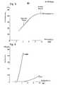
- Fig. 5 ein Diagramm des Zusammenhangs zwischen der Hochspannung einer Gleichspannungskorona und der Aufladespannung der Schichtoberfläche,
- Fig. 6 ein Diagramm des Aufladestromes der Korona in Abhängigkeit von der Koronaspannung bei unterschiedlichen Atmosphären,
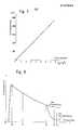
- Fig. 7 ein Diagramm des Zusammenhangs zwischen Schichtgewicht und der Sättigungsspannung der Schichtoberfläche, und
- Fig. 8 schematisch den Verlauf der Aufladungsspannung einer fotoleitfähigen Schicht in Abhängigkeit vom Transportweg der Schicht am Beispiel der Meßeinrichtung aus Fig. 3.
- 1 is a schematic side view of the measuring arrangement over the layer to be measured,
- 2 is a plan view of the measuring arrangement similar to FIG. 1 including a light source and supply units for the measuring device,
- 3 shows a schematic side view of a measuring arrangement for two measuring points,
- 4 schematically shows a processing line with a measuring arrangement for photoconductive layers,
- 5 shows a diagram of the relationship between the high voltage of a DC corona and the charging voltage of the layer surface,
- 6 shows a diagram of the charging current of the corona as a function of the corona voltage in different atmospheres,
- 7 shows a diagram of the relationship between layer weight and the saturation voltage of the layer surface, and
- 8 schematically shows the course of the charge voltage of a photoconductive layer as a function of the transport path of the layer using the example of the measuring device from FIG. 3.
Anhand der Fig. 1 und 2 wird die prinzipielle Meßanordnung zur Bestimmung der Schichtdicke erläutert. In Fig. 1 läuft eine dielektrische Schicht 15, beispielsweise eine Kunststoff-Folie, von einer Vorratsrolle in Transportrichtung A zu einer Aufwickelrolle. Die Transportbahn 5, entlang der die Schicht 15 läuft, führt über eine elektrisch leitende Auflage 16, die in nicht dargestellter Weise elektrisch mit Masse verbunden ist und die Gegenelektrode zu einer Korona 3 bildet, welche die Oberfläche der Schicht 15, mit einem konstanten Ladestrom auflädt. In Transportrichtung A gesehen ist ein elektrostatisches Voltmeter 4 als Meßsonde nachgeschaltet, das die jeweilige Aufladungsspannung der Schichtoberfläche mißt. Die Korona 3 wird beispielsweise mit einer Gleichspannung von rund 8 kV betrieben und weist entweder einen Koronadraht oder Koronaspitzen auf. Der Abstand des Koronadrahts bzw. der Koronaspitzen von der Schichtoberfläche liegt im Bereich von 5 bis 20 mm, bevorzugt beträgt dieser Abstand etwa 12 mm. Die Meßsonde bzw. das erste elektrostatische Voltmeter 4 ist mit seiner Meßfläche 0,5 bis 4 mm von der Schichtoberfläche entfernt. Die Bahngeschwindigkeit beträgt beispielsweise 8 m/min., jedoch sind auch wesentlich höhere Bahngeschwindigkeiten möglich.1 and 2, the basic measuring arrangement for determining the layer thickness is explained. In Fig. 1, a
Bei dem elektrostatischen Voltmeter 4 zur Bestimmung der Aufladungsspannung der Schichtoberfläche handelt es sich um ein bekanntes Gerät, das in der Unterseite, die der zu messenden Schicht zugewandt ist, ein Meßfenster für eine Meßelektrode aufweist. Eine Schwinggabel im Metallgehäuse des Voltmeters wird über einen frequenzmäßig abstimmbaren Antrieb von einem Oszillator in mechanische Schwingungen versetzt und ist elektrisch mit dem Metallgehäuse verbunden. Die aufeinander zu- und voneinander wegschwingenden Arme der Schwinggabel arbeiten als Zerhacker, der das Meßfenster periodisch öffnet und schließt. Die von der Aufladungsspannung bzw. dem Oberflächenpotential der Schicht ausgehenden elektrischen Kraftlinien verlaufen durch das Meßfenster hindurch auf die Meßelektrode und werden durch die hin- und hergehenden Arme der Schwinggabel, die sich quer zu den Kraftlinien bewegen, unterbrochen. Dadurch wird eine zerhackte Wechselspannung in der Meßelektrode induziert, deren Potential solange hochgeregelt wird, bis die Wechselspannungsamplitude ein Minimum erreicht. Damit ist das elektrische Feld zwischen Sonde und Schicht kompensiert und das Sondenpotential entspricht der Aufladespannung. Weitere Einzelheiten eines derartigen elektrostatischen Voltmeters sind beispielsweise in der deutschen Patentanmeldung P 34 09 701.5 beschrieben.The
Man kann statt dessen auch ein Feldmeßgerät verwenden, das jedoch größere Abstandsabhängigkeit mit sich bringt.You can also use a field meter instead, but this entails greater distance dependency.
Fig. 2 zeigt eine schematische Draufsicht auf die Meßanordnung nach Fig. 1 unter Einschluß der Versorgungseinheiten. Die Korona 3, die Lichtquelle 7 und die Meßsonde bzw. das elektrostatische Voltmeter 4 sind in einem gemeinsamen Gehäuse untergebracht, das nach unten hin in Richtung einer fotoleitfähigen und/oder dielektrischen Schicht 2 auf einem leitfähigen Trägermaterial 14 bzw. einer Schicht 15 in Gestalt einer Kunststoff-Folie, mit getrennter elektrisch leitender Auflage 16, offen ist. In das Innere einer Koronaabschirmung 13 wird über eine Druckleitung und eine Druckeinrichtung, beispielsweise einen Druckregler, Preßluft oder ein Schutzgas mit geringem Überdruck eingeleitet. Bei dem Schutzgas kann es sich zum Beispiel um Helium, Neon, Argon oder auch Stickstoff handeln. Das Schutzgas bzw. die Preßluft dient zum Einsatz der Meßeinrichtung an explosionsgefährdeten Stellen und unterdrückt die Zündung explosiver Gase durch Koronaentladung. Das Schutzgas dient auch der Steigerung der Koronaeffektivität und bietet dadurch den Vorteil der kontinuierlichen Schichtdickenmessung auch bei höheren Produktionsgeschwindigkeiten. Ein weiterer Vorteil liegt in der Vermeidung bzw. Verhinderung der Ozonbildung.FIG. 2 shows a schematic top view of the measuring arrangement according to FIG. 1 including the supply units. The
Die Korona 3 weist eine Abschirmung 13 aus isolierendem Material auf und wird mit einer Gleichspannung von 4 bis 12 kV betrieben. Die Höhe des Spannungspegels wird bestimmt durch den gewünschten Ladestrom und kann mit einem Konstantstromnetzteil automatisch nachgeregelt werden.The
Bei der Lichtquelle 7 kann es sich um eine Halogenlampe, eine Gasentladungslampe oder um lichtemittierenden Dioden handeln, die Licht in einem definierten Wellenlängenbereich aussenden und ein vorgegebenes Belichtungsfeld mit einer bestimmten Intensität ausleuchten. Bewährt hat sich eine Halogenleuchte, in deren Austrittsfenster Interferenz- und Graufilter einsetzbar sind. Damit läßt sich die Intensität und der Wellenlängenbereich dem jeweiligen Fotoleiter anpassen.The
Das elektrostatische Voltmeter 4 ist über eine Spannungsversorgung 21 mit einem x/t-Schreiber 12 verbunden, der in Abhängigkeit von der Zeit bzw. dem Transportweg der Schicht 2 oder 15 die von dem Voltmeter 4 gemessene Aufladungsspannung der Schichtoberfläche aufzeichnet. Hier kann natürlich auch eine andere Ausgabeeinheit sinnvoll sein, wie z.B. eine Voltmeteranzeige, eine CRT-Röhre oder ein Analog-Digitalwandler für Computerauswertung. Sämtliche Versorgungseinheiten, die in Fig. 2 durch eine gestrichelte Linie zusammengefaßt sind, bilden zusammen mit den in einem Gehäuse untergebrachten Einheiten, wie der Korona 3, der Lichtquelle 7 und dem Voltmeter 4, zusammen die Meßeinrichtung 1. Die Versorgungseinheiten können an eine nichtgezeigte Druckluftquelle angeschlossen sein, die beispielsweise die Versorgungseinheiten mit geringem Überdruck beaufschlagt. Die Versorgungseinheiten können mit den übrigen Einheiten der Meßeinrichtung 1 zusammengefaßt werden oder auch getrennt von diesen Einheiten außerhalb des Bereichs der Transportbahn der Schicht 2 oder 15 angeordnet sein. Das Gehäuse mit der Korona 3, der Lichtquelle 7 und dem elektrostatischen Voltmeter 4 ist entlang einer Führungsschiene 28 in Richtung des Pfeils B oder B' quer zur Transportrichtung A verschiebbar.The
Die schematische Seitenansicht einer Meßanordnung für zwei Meßstellen nach Fig. 3 zeigt die Korona 3, der ein erstes elektrostatisches Voltmeter 4 unmittelbar folgt. In einem Abstand, der von der Dunkelleitfähigkeit der Schicht abhängt, ist eine schaltbare Lichtquelle 9 angeordnet, an die ein zweites elektrostatisches Voltmeter 10 unmittelbar anschließt. Diese Baueinheiten schließt ein gemeinsames Gehäuse der Meßeinrichtung 1 ein. Eine derartige Meßanordnung ist vor allem zum Bestimmen der Schichtdicke dielektrischer Schichten vorgesehen, die eine gewisse Dunkelleitfähigkeit besitzen, die sich dadurch bemerkbar macht, daß die Aufladungsspannung der Schichtoberfläche durch Entladung durch die Schicht 2, die auf dem metallischen Schichtträger 14 aufgebracht ist, exponentiell abnimmt.3 shows the
In Fig. 4 ist schematisch eine Herstellungslinie für Druckplatten dargestellt, die aus einem Aluminiumschichtträger, auf den die fotoleitfähige Schicht 2 aufgebracht ist, gefertigt werden. Die Transportbahn 5 verläuft von einem nichtgezeigten Trockenkanal über eine Umlenkrolle 22 und eine Antriebswalze 25, sowie weitere Umlenkrollen 23 und 24 zu einer Aufwickelrolle 27. Um eine einfache Montage der Meßeinrichtung 1 bei möglichst geringer Vibration des Aluminiumschichtträgers zu erreichen, wird die Meßeinrichtung 1 über einer planaren Stelle 6 nahe der Antriebswalze 25 befestigt. Im Bereich der Antriebswalze 25 ist in Transportrichtung gesehen nach der Meßeinrichtung 1 eine Entladungslampe 11 angeordnet, die beispielsweise die elektrofotografische Schicht 2 auf dem Aluminiumschichtträger mit einer Bestrahlung von ca. 150 uJ/cm2 bei einer Bahngeschwindigkeit von 8 m/min. entlädt. Eine leitfähige Quetschrolle 26, die an der Antriebswalze 25 anliegt, kann die gleiche Aufgabe bei nicht lichtempfindlichen Schichten übernehmen. Es ist auch möglich, obwohl dies nicht dargestellt ist, die Meßeinrichtung 1 vor dem Trockenkanal für den beschichteten Aluminiumschichtträger anzuordnen und die Schichtdickenmessung somit für die noch feuchte, Lösungsmittel enthaltende Schicht vorzunehmen. Die Trocknung geschieht dann in einem nachfolgenden Trockenkanal.4 schematically shows a production line for printing plates, which are manufactured from an aluminum layer support on which the
Im folgenden werden anhand der Fig, 5 bis 8 die physikalischen Zusammenhänge zwischen der Schichtdicke und der Aufladungsspannung der Schichtoberfläche, die mittels der Korona erfolgt, erläutert.5 to 8, the physical relationships between the layer thickness and the charge voltage of the layer surface, which is carried out by means of the corona, are explained below.
Wird die auf eine Spannung U aufgeladene Schicht als ein Kondensator mit der Kapazität C betrachtet, so gilt für die auf die Schicht aufgebrachte Ladungsmenge
mit der Stromstärke I des Aufladestroms der Korona und der Einwirkungszeit t des Aufladestroms. Des weiteren folgt dann
mit der Fläche A der aufgeladenen Schicht, der Schichtdicke d und den Dielektrizitätskonstanten er des Schichtmaterials und ε0 der Luft.with the area A of the charged layer, the layer thickness d and the dielectric constant he of the layer material and ε0 of the air.
Aus Gleichung (1) und (2) ist


mit der Sprühlänge x der Korona und der Relativgeschwindigkeit v der Schicht zur Meßeinrichtung.with the spray length x of the corona and the relative speed v of the layer to the measuring device.
Aus (5) ergibt sich die Proportionalität zwischen der Schichtdicke d und der Aufladungsspannung U der Schicht, da die übrigen Größen, wie e0, er Materialkonstanten, x eine festvorgegebene geometrische Größe und v und I konstant gehaltene Betriebsgrößen sind.The proportionality between the layer thickness d and the charge voltage U of the layer results from (5), since the other variables, such as e0 , the material constants, x are a predetermined geometric variable and v and I are constant operating variables.
Bei Schichten mit hinreichend hoher Eigenleitfähigkeit ist es auch möglich, aus der Höhe der Sättigungsaufladung auf das Schichtgewicht rückzuschließen. Auch in diesem Fall besteht eine direkte Proportionalität zwischen der Aufladungsspannung U und der Schichtdicke d, wobei der Proportionalitätsfaktor den spezifischen Widerstand der Schicht enthält.In the case of layers with a sufficiently high intrinsic conductivity, it is also possible to draw conclusions about the layer weight from the level of the saturation charge. In this case too there is a direct proportionality between the charging voltage U and the layer thickness d, the proportionality factor containing the specific resistance of the layer.
Fig. 5 zeigt schematisch den Zusammenhang zwischen der Aufladespannung auf der Schichtoberfläche in Volt und der Hochspannung der Korona in kV. Für das Meßbeispiel liegt der kapazitive Bereich für die Messung der Aufladungsspannung bei einer Gleichspannung der Korona zwischen 2,3 bis knapp über 8 kV. Danach beginnt der ohm'sche Bereich, in welchem die Aufladungsspannung konstant bleibt, unabhängig von der weiter ansteigenden Spannung der Korona (Sättigungsbereich). Ab einer Spannung von ca. 10 kV der Korona beginnt der Durchschlagsbereich der Schicht.Fig. 5 shows schematically the relationship between the charging voltage on the layer surface in volts and the high voltage of the corona in kV. For the measurement example, the capacitive range for the measurement of the charging voltage at a DC voltage of the corona is between 2.3 to just over 8 kV. Then the ohmic range begins, in which the charging voltage remains constant, regardless of the further increasing voltage of the corona (saturation range). The breakdown range of the layer begins at a voltage of approx. 10 kV of the corona.
Fig. 6 gibt den Aufladestrom als Funktion der Koronaspannung an. Dabei zeigt es sich, daß der Aufladestrom eine starke Abhängigkeit von der Art des im Koronabereich befindlichen Gases zeigt. Bei einer Schutzgasatmosphäre aus Stickstoff fließt ein viel höherer Aufladestrom als bei ungespülter Korona. Dies ermöglicht eine rasche Aufladung der Schichtoberfläche und läßt bei sonst gleichem Koronaaufbau wesentlich höhere Bandgeschwindigkeiten zu. Eine ähnliche Wirkung zeigt sich auch mit anderen Schutzgasen, wie Argon und Helium, bei Preßluft oder reinem Sauerstoff zeigt sich keine Erhöhung des Aufladestromes.Fig. 6 gives the charging current as a function of the corona tension. It turns out that the charging current shows a strong dependence on the type of gas in the corona area. In a protective gas atmosphere made of nitrogen, a much higher charging current flows than in the case of non-purged corona. This enables the surface of the layer to be charged quickly and, with an otherwise identical corona structure, permits significantly higher belt speeds. A similar effect can also be seen with other protective gases, such as argon and helium, with compressed air or pure oxygen there is no increase in the charging current.
Wird in Fig. 7 über dem Schichtgewicht in g/m2 die Sättigungsspannung in kV aufgetragen, so ergibt sich in guter Näherung ein linearer Zusammenhang zwischen den beiden Größen, wobei für ein Schichtgewicht von 1 g/m2 mit einer Sättigungsspannung von 120 V zu rechnen ist. Dabei ist es unwesentlich, ob sich die Schicht aus einer oder mehreren Lagen zusammensetzt.If the saturation voltage in kV is plotted in FIG. 7 over the layer weight in g / m2 , a linear approximation results between the two quantities, with a saturation voltage of 120 V for a layer weight of 1 g / m2 to calculate. It is immaterial whether the layer is composed of one or more layers.
Fig. 8 zeigt den Verlauf der Aufladungsspannung über den Transportweg, den der Schichtträger 14 mit der fotoleitfähigen Schicht 2 gemäß der Anordnung nach Fig. 3 zurücklegt. An der Stelle xo erfolgt die Aufladung der Schicht 2 durch die Korona 3 und an der Stelle xl die erste Messung durch das erste elektrostatische Voltmeter 4. In einem Abstand von 3 bis 4 m von dem Voltmeter 4 ist ein zweites elektrostatisches Voltmeter 10 angeordnet, das die Aufladungshöhe nach einer definierten Zeit mißt.FIG. 8 shows the course of the charging voltage over the transport path which the
Da der exponentielle Abfall während der Entladung einer leitfähigen Schicht bekannt ist, kann aus den Werten der Aufladungsspannungen an der ersten und zweiten Meßstelle auf die Größe der Sättigungsspannung extrapoliert werden und somit gemäß dem linearen Zusammenhang nach Fig. 4 zwischen der Sättigungsspannung und dem Schichtgewicht das letztere und somit auch die Schichtdicke bestimmt werden.Since the exponential drop during the discharge of a conductive layer is known, it is possible to extrapolate from the values of the charge voltages at the first and second measuring points to the magnitude of the saturation voltage and thus the latter according to the linear relationship according to FIG. 4 between the saturation voltage and the layer weight and thus also the layer thickness can be determined.
Handelt es sich um eine fotoleitfähige Schicht und ist die Lichtquelle 9 eingeschaltet, so sinkt die Aufladungsspannung durch die Ausleuchtung zwischen x2 und x3 um einen Betrag, der eine Aussage über die Lichtempfindlichkeit, z.B. den E/2-Wert ermöglicht. Bei dem E/2-Wert handelt es sich um die Bestrahlung in J/m2 bzw. uJ/cm2, die gebraucht wird, um einen Fotoleiter bzw. eine fotoleitfähige Schicht von der Anfangsaufladungsspannung auf den halben Wert der Aufladungsspannung zu entladen. Aus der Spannungsdifferenz der belichteten und unbelichteten Stellen des Fotoleiters bzw. einer fotoleitfähigen Schicht läßt sich bei Kenntnis der Bestrahlung und der Annahme, daß der Spannungsabfall exponentiell verläuft, der E/2-Wert für die Fotoleiterschicht bestimmen.If it is a photoconductive layer and the light source 9 is switched on, the charging voltage drops by the illumination between x2 and x3 by an amount which enables a statement about the light sensitivity, for example the E / 2 value. The E / 2 value is the radiation in J / m2 or uJ / cm2 , which is used to discharge a photoconductor or a photoconductive layer from the initial charging voltage to half the value of the charging voltage. The E / 2 value for the photoconductor layer can be determined from the voltage difference between the exposed and unexposed areas of the photoconductor or a photoconductive layer when the irradiation is known and the assumption that the voltage drop is exponential.
Claims (28)
Translated fromGermanApplications Claiming Priority (2)
| Application Number | Priority Date | Filing Date | Title |
|---|---|---|---|
| DE3440197 | 1984-11-03 | ||
| DE19843440197DE3440197A1 (en) | 1984-11-03 | 1984-11-03 | METHOD FOR CONTINUOUS, CONTACTLESS LAYER THICKNESS DETERMINATION AND ARRANGEMENT FOR IMPLEMENTING THE METHOD |
Publications (3)
| Publication Number | Publication Date |
|---|---|
| EP0185884A1true EP0185884A1 (en) | 1986-07-02 |
| EP0185884B1 EP0185884B1 (en) | 1989-07-19 |
| EP0185884B2 EP0185884B2 (en) | 1992-10-07 |
Family
ID=6249421
Family Applications (1)
| Application Number | Title | Priority Date | Filing Date |
|---|---|---|---|
| EP85113564AExpired - LifetimeEP0185884B2 (en) | 1984-11-03 | 1985-10-25 | Method for the continuous and contactless measurement of film thickness as well as an arrangement for the realization of the method |
Country Status (6)
| Country | Link |
|---|---|
| US (1) | US4780680A (en) |
| EP (1) | EP0185884B2 (en) |
| JP (1) | JPS61114102A (en) |
| AU (1) | AU590732B2 (en) |
| CA (1) | CA1260539A (en) |
| DE (2) | DE3440197A1 (en) |
Families Citing this family (17)
| Publication number | Priority date | Publication date | Assignee | Title |
|---|---|---|---|---|
| US5101159A (en)* | 1990-05-18 | 1992-03-31 | Trek, Inc. | Electrostatic pin hole detector |
| US5119030A (en)* | 1990-05-18 | 1992-06-02 | Trek, Inc | Apparatus for electrically inspecting the surface of a drum |
| US5066918A (en)* | 1990-12-14 | 1991-11-19 | Eastman Kodak Company | Apparatus and method for measuring lateral charge distribution on a moving web |
| US6469513B1 (en) | 1992-11-12 | 2002-10-22 | Quality Engineering Associates, Inc. | Automated stationary/portable test system for applying a current signal to a dielectric material being tested |
| US5929640A (en)* | 1992-11-12 | 1999-07-27 | Quality Engineering Associates | Automated stationary/portable test system for photoconductive drums |
| US5508622A (en)* | 1994-12-14 | 1996-04-16 | Gatzlaff; Harold | Coating defect detector system |
| US5644223A (en)* | 1995-05-12 | 1997-07-01 | International Business Machines Corporation | Uniform density charge deposit source |
| US5485091A (en)* | 1995-05-12 | 1996-01-16 | International Business Machines Corporation | Contactless electrical thin oxide measurements |
| US5594247A (en)* | 1995-07-07 | 1997-01-14 | Keithley Instruments, Inc. | Apparatus and method for depositing charge on a semiconductor wafer |
| DE19525453A1 (en)* | 1995-07-13 | 1997-01-16 | Eltex Elektrostatik Gmbh | Device for removing the gaseous laminar boundary layer |
| US5767693A (en)* | 1996-09-04 | 1998-06-16 | Smithley Instruments, Inc. | Method and apparatus for measurement of mobile charges with a corona screen gun |
| US6060709A (en)* | 1997-12-31 | 2000-05-09 | Verkuil; Roger L. | Apparatus and method for depositing uniform charge on a thin oxide semiconductor wafer |
| US6538462B1 (en) | 1999-11-30 | 2003-03-25 | Semiconductor Diagnostics, Inc. | Method for measuring stress induced leakage current and gate dielectric integrity using corona discharge |
| DE10234217B4 (en)* | 2002-07-27 | 2009-02-05 | Hermann Kirchner Gmbh & Co Kg | Method and device for determining the thickness of an asphalt layer |
| KR100491987B1 (en)* | 2002-09-25 | 2005-05-30 | 마이크로 인스펙션 주식회사 | Apparatus for inspecting insulation layer of pdp panel |
| US6815974B1 (en) | 2003-07-14 | 2004-11-09 | Semiconductor Diagnostics, Inc. | Determining composition of mixed dielectrics |
| CN100535678C (en)* | 2003-11-12 | 2009-09-02 | 国际商业机器公司 | Ionization test for electrical verification |
Citations (5)
| Publication number | Priority date | Publication date | Assignee | Title |
|---|---|---|---|---|
| US2856582A (en)* | 1955-05-24 | 1958-10-14 | Gen Electric | Method and apparatus for measuring thickness |
| US3523246A (en)* | 1965-04-27 | 1970-08-04 | Brian Reginald Hall | Method of and apparatus for testing a laminar material for irregularities of thickness |
| DE2362835A1 (en)* | 1972-12-21 | 1974-07-04 | Oesterr Studien Atomenergie | DEVICE FOR CONTACTLESS DETECTION OR MEASUREMENT OF PREFERRED LIQUID COATINGS |
| GB2091872A (en)* | 1981-01-23 | 1982-08-04 | Twin City Int Inc | Measuring coating thicknesses on continuously moving material |
| EP0098509A2 (en)* | 1982-06-28 | 1984-01-18 | Coulter Systems Corporation | Electrostatic field control method and apparatus |
Family Cites Families (11)
| Publication number | Priority date | Publication date | Assignee | Title |
|---|---|---|---|---|
| US3646351A (en)* | 1971-02-16 | 1972-02-29 | Eastman Kodak Co | Gas-cushion corona charger |
| US3730753A (en)* | 1971-07-30 | 1973-05-01 | Eastman Kodak Co | Method for treating a web |
| US3935517A (en)* | 1975-01-02 | 1976-01-27 | Xerox Corporation | Constant current charging device |
| US3998538A (en)* | 1975-02-24 | 1976-12-21 | Xerox Corporation | Electrometer apparatus for reproduction machines |
| US4063155A (en)* | 1976-11-26 | 1977-12-13 | Xerox Corporation | D.C. Electrometer probe |
| US4286032A (en)* | 1978-04-27 | 1981-08-25 | Canon Kabushiki Kaisha | Electrophotographic process and apparatus therefor |
| NZ192629A (en)* | 1979-02-05 | 1983-05-31 | British Cellophane Ltd | Treating plastics film by corona discharge electrodes constructed and spaced to prevent arc discharges |
| US4451732A (en)* | 1982-05-20 | 1984-05-29 | Twin City International, Inc. | Apparatus for measuring thickness of coating on continuously moving material |
| DE3227025C2 (en)* | 1982-07-20 | 1985-06-13 | Wilhelm Dipl.-Ing. 4000 Düsseldorf Frede | Method for determining the weight per unit area or the layer thickness of a coated material web |
| DE3409701A1 (en)* | 1984-03-16 | 1985-09-19 | Hoechst Ag, 6230 Frankfurt | METHOD AND ARRANGEMENT FOR COMPLYING WITH A PRESENT POTENTIAL RATIO IN THE EXPOSURE OF ELECTROSTATICALLY CHARGED LIGHT SENSITIVE LAYERS |
| US4585323A (en)* | 1984-12-12 | 1986-04-29 | Xerox Corporation | Corona generating device |
- 1984
- 1984-11-03DEDE19843440197patent/DE3440197A1/ennot_activeWithdrawn
- 1985
- 1985-10-25DEDE8585113564Tpatent/DE3571692D1/ennot_activeExpired
- 1985-10-25EPEP85113564Apatent/EP0185884B2/ennot_activeExpired - Lifetime
- 1985-11-01USUS06/793,781patent/US4780680A/ennot_activeExpired - Fee Related
- 1985-11-01CACA000494476Apatent/CA1260539A/ennot_activeExpired
- 1985-11-04AUAU49379/85Apatent/AU590732B2/ennot_activeCeased
- 1985-11-05JPJP60246464Apatent/JPS61114102A/enactivePending
Patent Citations (5)
| Publication number | Priority date | Publication date | Assignee | Title |
|---|---|---|---|---|
| US2856582A (en)* | 1955-05-24 | 1958-10-14 | Gen Electric | Method and apparatus for measuring thickness |
| US3523246A (en)* | 1965-04-27 | 1970-08-04 | Brian Reginald Hall | Method of and apparatus for testing a laminar material for irregularities of thickness |
| DE2362835A1 (en)* | 1972-12-21 | 1974-07-04 | Oesterr Studien Atomenergie | DEVICE FOR CONTACTLESS DETECTION OR MEASUREMENT OF PREFERRED LIQUID COATINGS |
| GB2091872A (en)* | 1981-01-23 | 1982-08-04 | Twin City Int Inc | Measuring coating thicknesses on continuously moving material |
| EP0098509A2 (en)* | 1982-06-28 | 1984-01-18 | Coulter Systems Corporation | Electrostatic field control method and apparatus |
Non-Patent Citations (1)
| Title |
|---|
| ADH[SION, Nr. 6, 1980, Seiten 183-185, Stuttgart, DE; DR. U. ZORLL: "Messsysteme f}r die kontinuierliche Schichtdickenbestimmung"* |
Also Published As
| Publication number | Publication date |
|---|---|
| JPS61114102A (en) | 1986-05-31 |
| DE3440197A1 (en) | 1986-05-07 |
| EP0185884B1 (en) | 1989-07-19 |
| AU590732B2 (en) | 1989-11-16 |
| DE3571692D1 (en) | 1989-08-24 |
| CA1260539A (en) | 1989-09-26 |
| US4780680A (en) | 1988-10-25 |
| AU4937985A (en) | 1986-05-08 |
| EP0185884B2 (en) | 1992-10-07 |
Similar Documents
| Publication | Publication Date | Title |
|---|---|---|
| EP0185884B2 (en) | Method for the continuous and contactless measurement of film thickness as well as an arrangement for the realization of the method | |
| DE4312628C2 (en) | Image transmission method and device for carrying out this method | |
| DE3729286A1 (en) | MEASURING DEVICE FOR ANALYZING A GAS MIXTURE | |
| DE2543011A1 (en) | DEVICE FOR X-RAY FLUORESCENCE ANALYSIS | |
| DE2224660C3 (en) | DEVICE TO PREVENT FLAME OR EXPLOSION HAZARD IN ELECTROSTATIC COATING SYSTEMS | |
| DE2007728C3 (en) | Method and device for evaluating the distribution of the electrical charge on an electrostatically charged layer | |
| DE19545340C2 (en) | Device for checking area masses | |
| DE1077459B (en) | Device for determining the moisture content of materials or for controlling drying machines, drying devices and the like. like | |
| DE4321322B4 (en) | A method for the contactless determination of the residual moisture content of moving sheet material webs and apparatus for performing the method | |
| DE2526679A1 (en) | Investigation of air and water impurities - esp. very fine dust, using flameless atomic absorption spectroscopy | |
| DE2232513C3 (en) | Method for transferring a charge image and device for carrying out the method | |
| DE2242803C3 (en) | Procedure for eliminating static electricity | |
| DE4232185A1 (en) | Residual humidity measurement for moving material web - using screening effect on generated electrical field to determine humidity-dependent DC resistance of web | |
| DE3936719A1 (en) | METHOD AND DEVICE FOR MEASURING PAPER INFORMATION | |
| DE1813333A1 (en) | Method for measuring the layer thickness of a metal coating on an insulating strip | |
| DE2040757A1 (en) | Device for determining pores or pore holes in plastic films | |
| DE970472C (en) | Registration device for fast processes | |
| DE2815117C2 (en) | ||
| DE3302234C2 (en) | ||
| DE3586388T2 (en) | METHOD AND DEVICE FOR MONITORING THE COATING THICKNESS. | |
| DE1548245C (en) | Arrangement for the non-contact testing and measurement of the uniformity of the thickness of a web-shaped laminated material which comprises electrically conductive material | |
| DE2261963C2 (en) | Device for displaying changes in the thickness of objects which can be advanced on a path | |
| DE2060865A1 (en) | Device for measuring the extinction | |
| DE2139323C3 (en) | Device for measuring the toner concentration of the developer in a development station | |
| DE2118131C3 (en) | Method and device for charging an electrophotographic recording material |
Legal Events
| Date | Code | Title | Description |
|---|---|---|---|
| PUAI | Public reference made under article 153(3) epc to a published international application that has entered the european phase | Free format text:ORIGINAL CODE: 0009012 | |
| AK | Designated contracting states | Kind code of ref document:A1 Designated state(s):BE DE FR GB IT NL | |
| 17P | Request for examination filed | Effective date:19861108 | |
| 17Q | First examination report despatched | Effective date:19880301 | |
| GRAA | (expected) grant | Free format text:ORIGINAL CODE: 0009210 | |
| AK | Designated contracting states | Kind code of ref document:B1 Designated state(s):BE DE FR GB IT NL | |
| REF | Corresponds to: | Ref document number:3571692 Country of ref document:DE Date of ref document:19890824 | |
| ITF | It: translation for a ep patent filed | ||
| ET | Fr: translation filed | ||
| GBT | Gb: translation of ep patent filed (gb section 77(6)(a)/1977) | ||
| PLBI | Opposition filed | Free format text:ORIGINAL CODE: 0009260 | |
| 26 | Opposition filed | Opponent name:LEYBOLD AKTIENGESELLSCHAFT Effective date:19900414 | |
| NLR1 | Nl: opposition has been filed with the epo | Opponent name:LEYBOLD AG. | |
| PGFP | Annual fee paid to national office [announced via postgrant information from national office to epo] | Ref country code:DE Payment date:19911207 Year of fee payment:7 | |
| PUAH | Patent maintained in amended form | Free format text:ORIGINAL CODE: 0009272 | |
| STAA | Information on the status of an ep patent application or granted ep patent | Free format text:STATUS: PATENT MAINTAINED AS AMENDED | |
| PGFP | Annual fee paid to national office [announced via postgrant information from national office to epo] | Ref country code:FR Payment date:19920915 Year of fee payment:8 | |
| PGFP | Annual fee paid to national office [announced via postgrant information from national office to epo] | Ref country code:GB Payment date:19920921 Year of fee payment:8 | |
| 27A | Patent maintained in amended form | Effective date:19921007 | |
| AK | Designated contracting states | Kind code of ref document:B2 Designated state(s):BE DE FR GB IT NL | |
| PGFP | Annual fee paid to national office [announced via postgrant information from national office to epo] | Ref country code:BE Payment date:19921009 Year of fee payment:8 | |
| ITTA | It: last paid annual fee | ||
| PGFP | Annual fee paid to national office [announced via postgrant information from national office to epo] | Ref country code:NL Payment date:19921031 Year of fee payment:8 | |
| NLR2 | Nl: decision of opposition | ||
| ITF | It: translation for a ep patent filed | ||
| ET3 | Fr: translation filed ** decision concerning opposition | ||
| GBTA | Gb: translation of amended ep patent filed (gb section 77(6)(b)/1977) | Effective date:19921209 | |
| NLR3 | Nl: receipt of modified translations in the netherlands language after an opposition procedure | ||
| PG25 | Lapsed in a contracting state [announced via postgrant information from national office to epo] | Ref country code:DE Effective date:19930701 | |
| PG25 | Lapsed in a contracting state [announced via postgrant information from national office to epo] | Ref country code:GB Effective date:19931025 | |
| PG25 | Lapsed in a contracting state [announced via postgrant information from national office to epo] | Ref country code:BE Effective date:19931031 | |
| BERE | Be: lapsed | Owner name:HOECHST A.G. Effective date:19931031 | |
| PG25 | Lapsed in a contracting state [announced via postgrant information from national office to epo] | Ref country code:NL Effective date:19940501 | |
| NLV4 | Nl: lapsed or anulled due to non-payment of the annual fee | ||
| GBPC | Gb: european patent ceased through non-payment of renewal fee | Effective date:19931025 | |
| PG25 | Lapsed in a contracting state [announced via postgrant information from national office to epo] | Ref country code:FR Effective date:19940630 | |
| REG | Reference to a national code | Ref country code:FR Ref legal event code:ST |