EP0184391B1 - Sequence valve for piggyback iv administration - Google Patents
Sequence valve for piggyback iv administrationDownload PDFInfo
- Publication number
- EP0184391B1 EP0184391B1EP85308670AEP85308670AEP0184391B1EP 0184391 B1EP0184391 B1EP 0184391B1EP 85308670 AEP85308670 AEP 85308670AEP 85308670 AEP85308670 AEP 85308670AEP 0184391 B1EP0184391 B1EP 0184391B1
- Authority
- EP
- European Patent Office
- Prior art keywords
- tube
- latch
- sequence valve
- pincher
- tubing
- Prior art date
- Legal status (The legal status is an assumption and is not a legal conclusion. Google has not performed a legal analysis and makes no representation as to the accuracy of the status listed.)
- Expired - Lifetime
Links
Images


Classifications
- A—HUMAN NECESSITIES
- A61—MEDICAL OR VETERINARY SCIENCE; HYGIENE
- A61M—DEVICES FOR INTRODUCING MEDIA INTO, OR ONTO, THE BODY; DEVICES FOR TRANSDUCING BODY MEDIA OR FOR TAKING MEDIA FROM THE BODY; DEVICES FOR PRODUCING OR ENDING SLEEP OR STUPOR
- A61M5/00—Devices for bringing media into the body in a subcutaneous, intra-vascular or intramuscular way; Accessories therefor, e.g. filling or cleaning devices, arm-rests
- A61M5/14—Infusion devices, e.g. infusing by gravity; Blood infusion; Accessories therefor
- A61M5/168—Means for controlling media flow to the body or for metering media to the body, e.g. drip meters, counters ; Monitoring media flow to the body
- A61M5/16804—Flow controllers
- A61M5/16827—Flow controllers controlling delivery of multiple fluids, e.g. sequencing, mixing or via separate flow-paths
- F—MECHANICAL ENGINEERING; LIGHTING; HEATING; WEAPONS; BLASTING
- F16—ENGINEERING ELEMENTS AND UNITS; GENERAL MEASURES FOR PRODUCING AND MAINTAINING EFFECTIVE FUNCTIONING OF MACHINES OR INSTALLATIONS; THERMAL INSULATION IN GENERAL
- F16K—VALVES; TAPS; COCKS; ACTUATING-FLOATS; DEVICES FOR VENTING OR AERATING
- F16K7/00—Diaphragm valves or cut-off apparatus, e.g. with a member deformed, but not moved bodily, to close the passage ; Pinch valves
- F16K7/02—Diaphragm valves or cut-off apparatus, e.g. with a member deformed, but not moved bodily, to close the passage ; Pinch valves with tubular diaphragm
- F16K7/04—Diaphragm valves or cut-off apparatus, e.g. with a member deformed, but not moved bodily, to close the passage ; Pinch valves with tubular diaphragm constrictable by external radial force
- F16K7/06—Diaphragm valves or cut-off apparatus, e.g. with a member deformed, but not moved bodily, to close the passage ; Pinch valves with tubular diaphragm constrictable by external radial force by means of a screw-spindle, cam, or other mechanical means
- Y—GENERAL TAGGING OF NEW TECHNOLOGICAL DEVELOPMENTS; GENERAL TAGGING OF CROSS-SECTIONAL TECHNOLOGIES SPANNING OVER SEVERAL SECTIONS OF THE IPC; TECHNICAL SUBJECTS COVERED BY FORMER USPC CROSS-REFERENCE ART COLLECTIONS [XRACs] AND DIGESTS
- Y10—TECHNICAL SUBJECTS COVERED BY FORMER USPC
- Y10S—TECHNICAL SUBJECTS COVERED BY FORMER USPC CROSS-REFERENCE ART COLLECTIONS [XRACs] AND DIGESTS
- Y10S128/00—Surgery
- Y10S128/13—Infusion monitoring
- Y—GENERAL TAGGING OF NEW TECHNOLOGICAL DEVELOPMENTS; GENERAL TAGGING OF CROSS-SECTIONAL TECHNOLOGIES SPANNING OVER SEVERAL SECTIONS OF THE IPC; TECHNICAL SUBJECTS COVERED BY FORMER USPC CROSS-REFERENCE ART COLLECTIONS [XRACs] AND DIGESTS
- Y10—TECHNICAL SUBJECTS COVERED BY FORMER USPC
- Y10T—TECHNICAL SUBJECTS COVERED BY FORMER US CLASSIFICATION
- Y10T137/00—Fluid handling
- Y10T137/8158—With indicator, register, recorder, alarm or inspection means
- Y10T137/8225—Position or extent of motion indicator
- Y—GENERAL TAGGING OF NEW TECHNOLOGICAL DEVELOPMENTS; GENERAL TAGGING OF CROSS-SECTIONAL TECHNOLOGIES SPANNING OVER SEVERAL SECTIONS OF THE IPC; TECHNICAL SUBJECTS COVERED BY FORMER USPC CROSS-REFERENCE ART COLLECTIONS [XRACs] AND DIGESTS
- Y10—TECHNICAL SUBJECTS COVERED BY FORMER USPC
- Y10T—TECHNICAL SUBJECTS COVERED BY FORMER US CLASSIFICATION
- Y10T137/00—Fluid handling
- Y10T137/8593—Systems
- Y10T137/87153—Plural noncommunicating flow paths
- Y10T137/87161—With common valve operator
Definitions
- the present inventionrelates to a sequence valve for use with the administration of intravenous (IV) fluid, in particular the administration of multiple IV solutions or medications at predetermined intervals to a patient.
- IVintravenous
- first and second parallel flexible tubespass through a channel extending transversely through a housing.
- a coiled springwound about a shaft, the axis of the shaft being parallel to longitudinal direction of said flexible tubes where they pass through said channel.
- the coiled springhas one end connected to said shaft and a free end that extends between the two flexible tubes in said channel, the free end projecting out of said housing.
- the shaftis rotatable to a setting in which the spring is wound up to such an extent that its free end compresses a first one of the flexible tubes to such an extent that the tube becomes occluded. The shaft is then locked in this position.
- the springacts as a biasing means that causes its free end to normally maintain said first one of the tubes in an occluded state.
- a solenoid or any other suitable electromechanical devicehaving a linkage coupled to the free end of the spring where it projects out of the housing, is also provided, the arrangement being such that when the solenoid or said electromechanical device is energized the free end of the spring is moved against its biasing force to a setting in which it compresses the second of the two flexible tubes to such an extent that the second tube is occluded and the first of the two flexible tubes is no longer occluded.
- Claim 1has been divided into a two-part form with those features of Claim 1 that are already known from US-A-3 985 649 appearing in the pre-characterizing part.
- the sequence valve of the present inventionoperates on two tubes which are connected between the inlet of an IV control device (e.g. a pump or controller) and a pair of sources of IV fluids.
- the sequence valveis set to a first state in which the first tube is pinched off and the second is open.
- the sequence valvechanges to a second state in which the second tube is pinched off and the first tube is open.
- the sequence valvepreferably includes a base, a crank pivotally connected to the base, bias means for applying a bias force to the crank, occluder means connected to the crank, and releasable latch means for latching the crank in a first crank position.
- the occluder meansWhen the crank is in the first crank position, the occluder means occludes the first tube, and when when the crank is in the second crank position, the occluder means occludes the second tube.
- the bias forceurges the crank toward the second crank position, but when the crank is in the first crank position it is held there by the releasable latch means.
- the releasable latch meansreleases the crank, thus allowing the crank to move to the second crank position and allowing the sequence valve to switch from the first state to the second state.
- IV administration system 10includes IV pump 12, which pumps fluid from primary solution bag 14 or secondary (or piggyback) solution bag 16, to a patient (not shown).
- Sequence valve 18is connected between bags 14 and 16 and pump 12 to select one of the bags 14 and 16 for connection to pump 12.
- pump 12is an IV pump such as the AVI GUARDIAN 400.
- Pumps of this general type(which are described in U.S. Patent No. 4,236,880) use a disposable multiple rolling diaphragm pumping chamber 20 which is inserted into pump 12.
- Pumping chamber 20has an inlet tubing 22 connected at its inlet end, and an outlet tubing 24 at its outlet end.
- a drive mechanism within pump 12causes relative movement of two of the rolling diaphragms of pumping chamber 20 and the operation of two valves to cause fluid to be pumped from inlet tubing 22 through pumping chamber 20 and out through outlet tubing 24 to the patient.
- disposable multiple rolling diaphragm pumping chamber 20inlet tubing 22 and outlet tubing 24 form a part of a disposable IV administration set which also includes primary spike 26, primary drip chamber 28, primary tubing 30, proximal Y connector 32, primary roller clamp 34, secondary spike 36, secondary drip chamber 38, secondary tubing 40, secondary roller clamp 42, distal Y connector 44, distal tubing 46, needle 48, and distal roller clamp 50.
- Primary spike 26is inserted into the lower end of primary bag 14, and is connected to the upper end of primary drip chamber 28.
- the lower end of primary drip chamber 28is connected by primary tubing 30 to one leg of proximal Y connector 32.
- secondary spike 36is inserted into the lower end of secondary bag 16 and is connected to the upper end of secondary drip chamber 38.
- the lower end of secondary drip chamber 38is connected through secondary tubing 40 to the second leg of proximal Y connector 32.
- the third leg of Y connector 32is connected to inlet tubing 22.
- sequence valve 18is a lightweight, solenoid actuated device which initially pinches off primary tubing 30 to prevent flow from primary bag 14 while permitting flow from secondary bag 16 to pumping chamber 20.
- sequence valve 18switches so that secondary tubing 40 is pinched off and primary tubing 30 is unobstructed.
- secondary tubing 40is unobstructed and primary tubing 30 is pinched off, secondary (piggyback) bag 16 is connected to inlet tubing 22, and pump 12 pumps the secondary medication from piggyback bag 16 to the patient.
- secondary tubing 40is pinched off and primary tubing 30 is unobstructed, the primary solution is pumped from primary bag 14 to the patient by IV pump 12.
- outlet tubing 24is connected through distal Y connector 44 to distal tubing 46.
- needle 48At the end of distal tubing 46 is needle 48, which is inserted into a vein of the patient.
- Distal Y connector 44has another leg which is normally closed, but which allows the insertion of a syringe needle to introduce medication directly into distal tubing 46 as fluid is being pumped to the patient.
- Roller clamps 34, 42 and 50are used by medical personnel during the installation of the IV administration set into pump 12, during initial setup, and during removal of the IV administration set.
- FIG. 2shows a front view of pump 12.
- Pump 12includes a housing 54 which contains the electrical control circuitry and the mechanical portions of the pump which interact with disposable pumping chamber 20. Pump 12 is supported on an IV stand or pole (not shown) by pole clamp 56.
- Door 58covers a receptacle into which disposable pumping chamber 20 is inserted. In the embodiment shown in Figure 2, the opening of door 58 requires operation of the three separate devices: load control handle 60, door lock 62, and door latch 64.
- load control handle 60load control handle 60
- door lock 62door lock 62
- door latch 64During normal operation, when the IV administration set is installed with pumping chamber 20 within the receptacle of pump 12, door 58 is closed as shown in Figure 2.
- control panel 66In the lower left corner of the front of pump 12 is control panel 66, which includes a keyboard formed by numerical key pads ("0" through “9"), operate key pad (OPR) 68, standby key pad (STBY) 70, PRIMARY key pad 72, PIGGYBACK key pad 74, RATE key pad 76, volume limit (LIMIT) key pad 78, and volume infused clear (CLEAR) key pad 80.
- Control panel 66also includes three digital displays: rate display 82, volume limit display 84, and volume infused display 86.
- Pump 12also includes indicator panel 88, (which provides visual indication of different error or alarm conditions), and audio alarm annunciator 90.
- FIG. 3is an electrical block diagram of pump 12 and sequence valve 18, which are connected together by multiconductor cable 52 and connector 92
- Sequence valve 18receives a valve control signal from pump 12, and provides a valve state signal, which indicates which fluid line (primary tubing 30 or secondary tubing 40) is occluded.
- Pump control 94receives input signals from control panel 66, from sensors 96 (which sense various operating conditions or parameters such as output pressure, air bubbles in the IV administration set, empty bags and opening of door 58), and from sequence valve 18. Pump control 94 provides outputs to displays 82, 84 and 86 of control panel 66, indicator panel 88, audio annunciator 90 and to pump drive motor 98. In addition, when sequence valve 18 is connected to pump 12 and a piggyback operation has been selected, pump control 94 provides the valve control signal to sequence valve 18.
- Control panel 66allows the medical personnel to "set up” an IV administration schedule so that predetermined volumes of the primary and secondary solutions are delivered at predetermined rates.
- Pump control 94controls the operation of both sequence valve 18 and pump drive motor 98, so that it controls both the particular solution being pumped at any given time, and the rate at which the fluid is being pumped.
- the medical personnelplaces pump 12 in a standby mode. This allows changing or resetting of both rates and volume limits for both the primary and piggyback solutions.
- the primary solution rateis selected by depressing PRIMARY key pad 72 and then RATE key pad 76, followed by the keys representing the numerical value desired.
- the primary volume limitscan then be set by pressing LIMIT key pad 78 and then using the numerical keys to enter the desired numerical limit for the primary solution.
- PIGGYBACK key pad 74is pressed.
- RATE key pad 76is then pressed, followed by appropriate numerical keys to enterthe piggyback rate.
- LIMIT key pad 78is then depressed, followed by selected numerical key pads to set the piggyback volume limit.
- Pump control 94stores the rates and volume limits entered for both the primary solution and the piggyback solution. These stored values are used, together with an accumulated volume infused value in controlling sequence valve 18 as well as pump drive motor 98.
- Sequence valve 18 of the present inventionis a spring loaded, solenoid actuated device which initially occludes primary tubing 30 so that the secondary solution is pumped first. Sequence valve 18 is placed in this initial condition by inserting primary tubing 30 into one slot of sequence valve 18 and then cocking lever 100 so that primary tubing 30 is occluded. Secondary tubing 40 is then inserted into an adjacent slot alongside primary tubing 30 in sequence valve 18 as shown in Figure 1.
- Pump control 94provides pump drive control signals to pump drive motor 98 which cause motor 98 to produce the pumping rate stored for the piggyback solution.
- pump control 94maintains an accumulated value which represents the amount of secondary solution which has been pumped with sequence valve 18 in its initial setting.
- a valve control signalis produced which causes sequence valve 18 to change state.
- pump control 94Upon receiving the signal from sequence valve 18 indicating that the change has been made, pump control 94 provides pump drive signals which cause pump drive motor 98 to operate at the pumping rate selected for the primary solution. Pump control 94 again maintains an accumulated value which represents the amount of primary solution which has been pumped. This value is displayed on volume infused display 86. When the accumulated value reaches the stored primary volume limit, pump control 94 halts operation of pump drive motor 98 and provides an indication through indicator panel 88 and audio annunciator 90 that both the piggyback and primary administration has been completed. At that point, the medical personnel responsible for the IV administration are required to intervene to set a new schedule of primary and piggyback rates and volume rates.
- the present inventionis advantageous because all of the medication for a single day or for several days can be stored in one large secondary bag 16, as opposed to much smaller secondary bags which run dry after each administration of that medication. For example, if a patient is to receive 50 milliliters of secondary medication four times a day, four bags would be required with the prior art systems, in which the switching from the secondary bag to the primary solution is determined by when the secondary bag is empty. With the system of the present invention, one 200 milliliter bag can be used for the entire day. Since a large or a small bag costs essentially the same, there is a cost saving just by virtue of the reduced number of bags. In addition, the system significantly reduces the amount of time which is required of medical personnel. It is not necessary to change the secondary bag 16 after each administration of medication, and in fact the present invention allows the secondary medication to be provided multiple times without a change in the secondary bag.
- sequence valve 18can be suspended from the tubing (e.g. primary tubing 30) rather than requiring separate clamping to a pole. This makes sequence valve 18 simpler and easier to use, and makes it portable so that sequence valve 18 can be moved wherever pump 12 is moved.
- tubinge.g. primary tubing 30
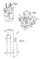
- Figures 4 through 7show a first preferred embodiment of sequence valve 18.
- Figure 4shows valve 18 in its normal initial operating position for piggyback operation.
- tubes 30 and 40pass side-by-side through valve 18.
- retainer spring 102which has a pair of retainer arms 102A and 102B.
- tubing 30 and tubing 40are retained in side-by-side position by retaining fingers 104A and 104B of front cover 106.
- lever 100is in its uppermost ("cocked") position, which causes occluder stud 108 to be in its leftmost position.
- primary tubing 30is pinched off between occluder stud 108 and leaf spring 110.
- sequence valve 18has received a valve control signal from pump 12 which causes occluder stud 108 to move generally to the right to pinch off secondary tubing 40 between occluder stud 108 and wall 112.
- sequence valve 18has two stable positions, one in which primary tubing 30 is occluded and secondary tubing 40 is unoc- cluded; and the other in which secondary tubing 40 is occluded and primary tubing 30 is unoc- cluded.
- Figure 5shows sequence valve 18 with front cover 106 removed.
- the operating mechanisms of sequence valve 18are supported by valve base 114.
- Both occluder stud 108 and lever 100are attached to bell crank 116, which is pivotally mounted to valve base 114 by pivot pin 118.
- Bell crank 116is biased in a clockwise direction by bias spring 120, which is connected at its upper end to stud 122 and thus to valve base 114, and which is connected at its lower end to stud 124 which projects rearwardly from the lower end of bell crank 118.
- Latch 126is pivotally mounted about pivot pin 128, and has a latch tooth 130 which engages lower leg 132 of bell crank 116 when lever 116 is its cocked upper position.
- Latch arm 134is held in the initial position by solenoid plunger 136, which prevents rotation of latch 126 about the axis defined by pivot pin 128.
- Valve 18will remain in a stable initial position until a valve control signal actuates solenoid 138 ( Figure 6).
- solenoid plunger 136This causes solenoid plunger 136 to be pulled in a rearward direction out of contact with arm 134 of latch 126 This allows the bias force of spring 120 to rotate bell crank 116 and in turn latch 126 about their respective pivot pins 118 and 128 to the position shown in phantom in Figure 5.
- the second stable position of bell crank 116is defined by stop 140, which engages leg 132 of bell crank 116 to prevent further rotation in the clockwise direction. In this second stable state, occluder stud 108 is at its rightmost position, so that secondary tubing 40 is pinched off between occluder stud 108 and wall 112.
- Sequence valve 18is reset to its initial position by moving lever 100 upwards to the initial cocked position shown in solid lines.
- Latch spring 142urges latch 126 back to its initial position when sequence valve 18 is being reinitialized.
- rear surface 134A of arm 134is bevelled to form a ramp which allows arm 134 to move past solenoid plunger 136 as lever 100 is being cocked.
- Solenoid 138includes a solenoid plunger stud 144 which extends out the rear end of solenoid cover 146.
- solenoid button 148At the rear end of solenoid plunger stud 144 is solenoid button 148. This button allows the nurse or technician to pull solenoid plunger 136 out of the way of latch 126 in order to manually release lever 100, bell crank 116 and latch 126 from the cocked position. Button 148 can then be released and, due to the bias force of bias spring 150 solenoid plunger 136 returns to its normal position shown in Figure 6.
- sequence valve 18It is also preferable for sequence valve 18 to provide an electrical signal which indicates the current state of sequence valve 18.
- a metal contact stud 152is attached to bell crank 116.
- contact stud 152When valve 18 is in its initial state, contact stud 152 is in contact with contact wire 154.
- contact stud 152When the valve control signal has been received and bell crank 116 has rotated to the position shown in phantom, contact stud 152 has moved into engagement with contact wire 156.
- a different electrical signalis supplied through cable 152 to pump 12. This provides a simple, yet very effective way of indicating the state of sequence valve 18 to pump 12.
- upper retainer 102is a single wire clip which mounts over stud 158 at the upper end of valve base 114.
- the resilient nature of retainer 102allows the retainer arms 102A and 102B to be displaced outwardly while tubing 30 and 40 are inserted into sequence valve 18. Once released, arms 102A and 102B return to their normal position shown in Figure 7, thus securely holding tubing 30 and tubing 40 in place.
- Sequence valve 18 shown in Figures 4-7is particularly advantageous, since it is small, lightweight (so that it can be supported on tubing 30 and 40 without the need for a separate support stand) and uses a small, low-power solenoid.
- a pivoted latch 126 and a pivoted bell crank 116both of which provide a substantial mechanical advantage (e.g. 4:0 each)
- solenoid plunger 136provides the sufficient force to move occluder stud 108 to the right so as to pinch off tubing 40.
- the force required to move solenoid plunger 136is, for example, only one-sixteenth of the force applied by occluder stud 108 to tubing 40.
- Sequence valve 18 shown in Figures 4-7also uses an extremely simple mechanism to pinch off alternately either tubing 30 or tubing 40.
- leaf spring 110to urge tubing 30 toward occluder stud 108
- sequence valve 18does not require a precise alignment of both positions of occluder stud 108, and variations in the diameters of tubing 30 and 40 are accommodated. It is merely necessary to ensure that occluder stud 108 moves far enough to the right to pinch off tubing 40 against right wall 112 for the minimum expected diameter of tubing 40.
- FIGs 8-12show a second embodiment of the sequence valve of the present invention.
- This second embodiment(which is designated valve 18') is generally similar to the embodiment of sequence valve 18 shown in Figures 4-7, and similar reference numerals are used to designate similar elements.
- the internal operation of the bell crank, latch and solenoid of sequence valve 18' of Figures 8-12are identical to those shown in Figures 4-7 and will not be discussed again.
- sequence valve 18' of Figures 8-12 and sequence valve 18 of Figures 4-7The main difference between sequence valve 18' of Figures 8-12 and sequence valve 18 of Figures 4-7 is in the retaining of tubing 30 and 40.
- a tube retainer 200is pivotally mounted at the upper end of valve 18' between top end plate 202 and the upper ends of front cover 106 and valve base 114.
- Tube retainer 200has a right leg 20 which is pivotally mounted about pivot pin 206, a left leg 208, a front flange 210, and a tube hold-down flange 212.
- the closed position of tube retainer 200is shown in Figures 8-10, and the open position is shown in Figure 11.
- Flange 210forms a handle by which the nurse can pivot tube retainer 200 to the open position to allow insertion or removal of tubing 30 and 40 from sequence valve 18'.
- Left leg 208 of tube retainer 200contains a hole 214 which receives a spring loaded ball 216 mounted in top plate 202 when tube retainer 200 is in the closed position shown in Figures 8-10.
- Spring loaded ball 216maintains tube retainer 200 in the closed position and prevents it from moving from the closed position if IV pump 12 or tubing 30 or 40 are moved or bumped inadvertently.
- Sequence valve 18also uses tube retainer 200 as a switch to indicate to pump 12 that sequence valve 18' is in a condition to operate.
- tube retainer 200is an electrically conductive material, preferably metal.
- An electrically conductive washer 218, which is partially shown in Figure 11,is mounted on pivot pin 206 in contact with right leg 204 of tube retainer 200.
- Spring Contact 220is positioned so that it will be engaged by left leg 208 when tube retainer 200 is in the closed position. Thus when tube retainer 200 is in the closed position, a closed electrical path is provided between conductive washer 218 and spring contact 220.
- Figure 12shows an electrical schematic diagram of sequence valve 18'.
- cable 152(which connects valve 18' to pump control 94) contains four wires 152A, 152B, 152C and 152D.
- Solenoid 138is connected between wires 152A and 152B.
- Wire 152Bis connected to ground.
- pump control 94causes a voltage to be present between wires 152A and 152B, solenoid 138 is actuated.
- Wires 152C and 152Dare used to indicate to pump control 94 the condition or state of sequence valve 18'.
- the switch formed by tube retainer 200, conductive washer 218 and spring contact 220is connected in series with a switch formed by contact stud 152 and contact wires 154 and 156.
- Contact wire 154is connected to wire 152D
- contact wire 156is connected to wire 152C.
- both wires 152C and 152Dwill indicate an open circuit.
- pump control 94can determine the operating state of sequence valve 18', as well as whether tube retainer 200 is in closed position.
- Figures 8-11also show retainer posts 222 and 224, which are positioned along the channel, and which maintain tubing 30 and 40 in position along the entire length of the channel.
- valve 18'At the upper end of valve 18' is hook 226, which is attached by screw 228 to top plate 202. Primary tubing 30 is threaded through hook 226 to main- tai.n sequence valve 18' in a generally vertical position. This counteracts the tendency of the lower end of valve 18' to tip forward due to the greater weight of solenoid 138 within solenoid housing 146 (see Figure 6).
- sequence valve 18'Also included in sequence valve 18' is a spring clip 230 and retainer pad 232 which are positioned along the left side of sequence valve 18'.
- Clip 230allows sequence valve 18' to be clipped onto pump 12 when not in use.
- pad 232prevents sequence valve 18' from slipping when it is clipped onto pump 12.
Landscapes
- Health & Medical Sciences (AREA)
- Engineering & Computer Science (AREA)
- Animal Behavior & Ethology (AREA)
- General Health & Medical Sciences (AREA)
- Biomedical Technology (AREA)
- Heart & Thoracic Surgery (AREA)
- Hematology (AREA)
- Life Sciences & Earth Sciences (AREA)
- Vascular Medicine (AREA)
- Anesthesiology (AREA)
- Public Health (AREA)
- Veterinary Medicine (AREA)
- General Engineering & Computer Science (AREA)
- Mechanical Engineering (AREA)
- Infusion, Injection, And Reservoir Apparatuses (AREA)
- External Artificial Organs (AREA)
Description
- The present invention relates to a sequence valve for use with the administration of intravenous (IV) fluid, in particular the administration of multiple IV solutions or medications at predetermined intervals to a patient.
- It is quite common in IV therapy to give a patient a primary solution and one or more secondary solutions or medications. The secondary (or piggyback") medication is usually given several times a day. An example is when a patient is on antibiotics. It is desirable to have an IV pump and a sequencing valve that administers the primary and secondary solutions sequentially.
- In the past, there have been IV pump systems which allow two fluids to be administered. In these systems, the secondary medication is pumped until the secondary container goes empty, and then the pump switches to the primary fluid. An example of this type of system is shown in U.S. Patent 4,451,255. This proves to be a substantial burden to hospital personnel, particularly where the secondary medication is required several times a day. With the prior art systems, the medical personnel must change secondary medication bags several times each day.
- A prior art that is of particular interest is that disclosed in US-A-3 895 649. In this prior art first and second parallel flexible tubes pass through a channel extending transversely through a housing. Within the housing is a coiled spring wound about a shaft, the axis of the shaft being parallel to longitudinal direction of said flexible tubes where they pass through said channel. The coiled spring has one end connected to said shaft and a free end that extends between the two flexible tubes in said channel, the free end projecting out of said housing. The shaft is rotatable to a setting in which the spring is wound up to such an extent that its free end compresses a first one of the flexible tubes to such an extent that the tube becomes occluded. The shaft is then locked in this position. Thus, the spring acts as a biasing means that causes its free end to normally maintain said first one of the tubes in an occluded state. A solenoid or any other suitable electromechanical device having a linkage coupled to the free end of the spring where it projects out of the housing, is also provided, the arrangement being such that when the solenoid or said electromechanical device is energized the free end of the spring is moved against its biasing force to a setting in which it compresses the second of the two flexible tubes to such an extent that the second tube is occluded and the first of the two flexible tubes is no longer occluded.
- The sequence valve of the present invention is as defined in the accompanying claims. Claim 1 has been divided into a two-part form with those features of Claim 1 that are already known from US-A-3 985 649 appearing in the pre-characterizing part.
- The sequence valve of the present invention operates on two tubes which are connected between the inlet of an IV control device (e.g. a pump or controller) and a pair of sources of IV fluids. The sequence valve is set to a first state in which the first tube is pinched off and the second is open.
- In response to a valve control signal, the sequence valve changes to a second state in which the second tube is pinched off and the first tube is open.
- The sequence valve preferably includes a base, a crank pivotally connected to the base, bias means for applying a bias force to the crank, occluder means connected to the crank, and releasable latch means for latching the crank in a first crank position. When the crank is in the first crank position, the occluder means occludes the first tube, and when when the crank is in the second crank position, the occluder means occludes the second tube.
- The bias force urges the crank toward the second crank position, but when the crank is in the first crank position it is held there by the releasable latch means. In response to a control signal, the releasable latch means releases the crank, thus allowing the crank to move to the second crank position and allowing the sequence valve to switch from the first state to the second state.
- Figure 1 is a partially schematic diagram of a preferred embodiment of the IV administration system using the sequence valve of the present invention.
- Figure 2 is a front view of the IV pump of Figure 1.
- Figure 3 is an electrical block diagram of the system of Figure 1.
- Figure 4 is a front view of a first preferred embodiment of the sequence valve.
- Figure 5 is a front view of the sequence valve of Figure 4 with the front cover removed.
- Figure 6 is a sectional view along section 6-6 of Figure 5.
- Figure 7 is a top view of the valve of Figure 4.
- Figure 8 is a front view of a second preferred embodiment of the sequence valve.
- Figures 9 and 10 are partial left and right side views of the sequence valve of Figure 8.
- Figure 11 is a top view of the sequence valve of Figure 8 with the tube retainer pivoted to its open position.
- Figure 12 is an electrical schematic diagram of the sequence valve of Figure 8.
- In the preferred embodiment shown in Figure 1, IV administration system 10 includes IV
pump 12, which pumps fluid fromprimary solution bag 14 or secondary (or piggyback) solution bag 16, to a patient (not shown).Sequence valve 18 is connected betweenbags 14 and 16 andpump 12 to select one of thebags 14 and 16 for connection to pump 12. - In the particular embodiment shown in Figure 1,
pump 12 is an IV pump such as the AVI GUARDIAN 400. Pumps of this general type (which are described in U.S. Patent No. 4,236,880) use a disposable multiple rollingdiaphragm pumping chamber 20 which is inserted intopump 12.Pumping chamber 20 has aninlet tubing 22 connected at its inlet end, and anoutlet tubing 24 at its outlet end. A drive mechanism withinpump 12 causes relative movement of two of the rolling diaphragms ofpumping chamber 20 and the operation of two valves to cause fluid to be pumped frominlet tubing 22 throughpumping chamber 20 and out throughoutlet tubing 24 to the patient. - In the embodiment shown in Figure 1, disposable multiple rolling
diaphragm pumping chamber 20,inlet tubing 22 andoutlet tubing 24 form a part of a disposable IV administration set which also includesprimary spike 26,primary drip chamber 28,primary tubing 30,proximal Y connector 32,primary roller clamp 34,secondary spike 36,secondary drip chamber 38,secondary tubing 40,secondary roller clamp 42,distal Y connector 44,distal tubing 46,needle 48, and distal roller clamp 50. Primary spike 26 is inserted into the lower end ofprimary bag 14, and is connected to the upper end ofprimary drip chamber 28. The lower end ofprimary drip chamber 28 is connected byprimary tubing 30 to one leg ofproximal Y connector 32.- Similarly,
secondary spike 36 is inserted into the lower end of secondary bag 16 and is connected to the upper end ofsecondary drip chamber 38. The lower end ofsecondary drip chamber 38 is connected throughsecondary tubing 40 to the second leg ofproximal Y connector 32. The third leg ofY connector 32 is connected toinlet tubing 22. Primary tubing 30 andsecondary tubing 40 pass throughsequence valve 18, and at least one (preferably primary tubing 30) supportssequence valve 18. In the preferred embodiment of the present invention,sequence valve 18 is a lightweight, solenoid actuated device which initially pinches offprimary tubing 30 to prevent flow fromprimary bag 14 while permitting flow from secondary bag 16 to pumpingchamber 20. In response to a valve control signal received frompump 12 throughmulticonductor cable 52,sequence valve 18 switches so thatsecondary tubing 40 is pinched off andprimary tubing 30 is unobstructed. Whensecondary tubing 40 is unobstructed andprimary tubing 30 is pinched off, secondary (piggyback) bag 16 is connected toinlet tubing 22, and pump 12 pumps the secondary medication from piggyback bag 16 to the patient. Conversely, whensecondary tubing 40 is pinched off andprimary tubing 30 is unobstructed, the primary solution is pumped fromprimary bag 14 to the patient by IVpump 12.- At the outlet end,
outlet tubing 24 is connected throughdistal Y connector 44 to distaltubing 46. At the end ofdistal tubing 46 isneedle 48, which is inserted into a vein of the patient.Distal Y connector 44 has another leg which is normally closed, but which allows the insertion of a syringe needle to introduce medication directly intodistal tubing 46 as fluid is being pumped to the patient. - Roller clamps 34, 42 and 50 are used by medical personnel during the installation of the IV administration set into
pump 12, during initial setup, and during removal of the IV administration set. - Figure 2 shows a front view of
pump 12.Pump 12 includes ahousing 54 which contains the electrical control circuitry and the mechanical portions of the pump which interact withdisposable pumping chamber 20.Pump 12 is supported on an IV stand or pole (not shown) bypole clamp 56.Door 58 covers a receptacle into whichdisposable pumping chamber 20 is inserted. In the embodiment shown in Figure 2, the opening ofdoor 58 requires operation of the three separate devices: load control handle 60,door lock 62, anddoor latch 64. During normal operation, when the IV administration set is installed with pumpingchamber 20 within the receptacle ofpump 12,door 58 is closed as shown in Figure 2. - In the lower left corner of the front of
pump 12 iscontrol panel 66, which includes a keyboard formed by numerical key pads ("0" through "9"), operate key pad (OPR) 68, standby key pad (STBY) 70, PRIMARYkey pad 72, PIGGYBACKkey pad 74, RATEkey pad 76, volume limit (LIMIT)key pad 78, and volume infused clear (CLEAR)key pad 80.Control panel 66 also includes three digital displays:rate display 82,volume limit display 84, and volume infuseddisplay 86. Pump 12 also includesindicator panel 88, (which provides visual indication of different error or alarm conditions), andaudio alarm annunciator 90.- Figure 3 is an electrical block diagram of
pump 12 andsequence valve 18, which are connected together bymulticonductor cable 52 andconnector 92Sequence valve 18 receives a valve control signal frompump 12, and provides a valve state signal, which indicates which fluid line (primary tubing 30 or secondary tubing 40) is occluded. - The operation of
pump 12 is controlled bypump control 94, which in preferred embodiments includes a microcomputer, together with associated memory, timing and clock circuitry and appropriate interface circuitry.Pump control 94 receives input signals fromcontrol panel 66, from sensors 96 (which sense various operating conditions or parameters such as output pressure, air bubbles in the IV administration set, empty bags and opening of door 58), and fromsequence valve 18.Pump control 94 provides outputs todisplays control panel 66,indicator panel 88,audio annunciator 90 and to pumpdrive motor 98. In addition, whensequence valve 18 is connected to pump 12 and a piggyback operation has been selected,pump control 94 provides the valve control signal to sequencevalve 18. Control panel 66 allows the medical personnel to "set up" an IV administration schedule so that predetermined volumes of the primary and secondary solutions are delivered at predetermined rates.Pump control 94 controls the operation of bothsequence valve 18 and pump drivemotor 98, so that it controls both the particular solution being pumped at any given time, and the rate at which the fluid is being pumped.- By depressing STBY
key pad 70, the medical personnel places pump 12 in a standby mode. This allows changing or resetting of both rates and volume limits for both the primary and piggyback solutions. The primary solution rate is selected by depressing PRIMARYkey pad 72 and then RATEkey pad 76, followed by the keys representing the numerical value desired. The primary volume limits can then be set by pressing LIMITkey pad 78 and then using the numerical keys to enter the desired numerical limit for the primary solution. - For the piggyback or secondary solution, PIGGYBACK
key pad 74 is pressed. RATEkey pad 76 is then pressed, followed by appropriate numerical keys to enterthe piggyback rate. LIMITkey pad 78 is then depressed, followed by selected numerical key pads to set the piggyback volume limit. Pump control 94 stores the rates and volume limits entered for both the primary solution and the piggyback solution. These stored values are used, together with an accumulated volume infused value in controllingsequence valve 18 as well as pump drivemotor 98.Sequence valve 18 of the present invention is a spring loaded, solenoid actuated device which initially occludesprimary tubing 30 so that the secondary solution is pumped first.Sequence valve 18 is placed in this initial condition by insertingprimary tubing 30 into one slot ofsequence valve 18 and then cockinglever 100 so thatprimary tubing 30 is occluded.Secondary tubing 40 is then inserted into an adjacent slot alongsideprimary tubing 30 insequence valve 18 as shown in Figure 1.- Operation of
pump 12 in the piggyback mode is initiated by depressing OPRkey pad 18.Pump control 94 provides pump drive control signals to pumpdrive motor 98 which causemotor 98 to produce the pumping rate stored for the piggyback solution. Aspump drive motor 98 is operated,pump control 94 maintains an accumulated value which represents the amount of secondary solution which has been pumped withsequence valve 18 in its initial setting. When that accumulated value reaches the piggyback volume limit stored bypump control 94, a valve control signal is produced which causessequence valve 18 to change state.Sequence valve 18, in response to the valve control signal, occludessecondary tubing 40, and allows primary solution to flow throughprimary tubing 30, toinlet tubing 22. Upon receiving the signal fromsequence valve 18 indicating that the change has been made, pumpcontrol 94 provides pump drive signals which causepump drive motor 98 to operate at the pumping rate selected for the primary solution.Pump control 94 again maintains an accumulated value which represents the amount of primary solution which has been pumped. This value is displayed on volume infuseddisplay 86. When the accumulated value reaches the stored primary volume limit,pump control 94 halts operation ofpump drive motor 98 and provides an indication throughindicator panel 88 andaudio annunciator 90 that both the piggyback and primary administration has been completed. At that point, the medical personnel responsible for the IV administration are required to intervene to set a new schedule of primary and piggyback rates and volume rates. - The present invention is advantageous because all of the medication for a single day or for several days can be stored in one large secondary bag 16, as opposed to much smaller secondary bags which run dry after each administration of that medication. For example, if a patient is to receive 50 milliliters of secondary medication four times a day, four bags would be required with the prior art systems, in which the switching from the secondary bag to the primary solution is determined by when the secondary bag is empty. With the system of the present invention, one 200 milliliter bag can be used for the entire day. Since a large or a small bag costs essentially the same, there is a cost saving just by virtue of the reduced number of bags. In addition, the system significantly reduces the amount of time which is required of medical personnel. It is not necessary to change the secondary bag 16 after each administration of medication, and in fact the present invention allows the secondary medication to be provided multiple times without a change in the secondary bag.
- By use of
pump control 94 withinhousing 54 ofpump 12 to control operation of both pump 12 andsequence valve 18, the size, weight, complexity and cost ofsequence valve 18 are significantly reduced. As a result,sequence valve 18 can be suspended from the tubing (e.g. primary tubing 30) rather than requiring separate clamping to a pole. This makessequence valve 18 simpler and easier to use, and makes it portable so thatsequence valve 18 can be moved whereverpump 12 is moved. - Figures 4 through 7 show a first preferred embodiment of
sequence valve 18. Figure 4 showsvalve 18 in its normal initial operating position for piggyback operation. As shown in Figure 4,tubes valve 18. At the upper end,tubing 30 andtubing 40 are retained byretainer spring 102, which has a pair of retainer arms 102A and 102B. At the lower end,tubing 30 andtubing 40 are retained in side-by-side position by retainingfingers front cover 106. - As shown in Figure 4,
lever 100 is in its uppermost ("cocked") position, which causesoccluder stud 108 to be in its leftmost position. As a result,primary tubing 30 is pinched off betweenoccluder stud 108 andleaf spring 110. Also shown in phantom in Figure 4 is the position oflever 100 and the position ofoccluder stud 108 aftersequence valve 18 has received a valve control signal frompump 12 which causesoccluder stud 108 to move generally to the right to pinch offsecondary tubing 40 betweenoccluder stud 108 andwall 112. Thussequence valve 18 has two stable positions, one in whichprimary tubing 30 is occluded andsecondary tubing 40 is unoc- cluded; and the other in whichsecondary tubing 40 is occluded andprimary tubing 30 is unoc- cluded. - Figure 5 shows
sequence valve 18 withfront cover 106 removed. The operating mechanisms ofsequence valve 18 are supported byvalve base 114. Bothoccluder stud 108 andlever 100 are attached to bell crank 116, which is pivotally mounted tovalve base 114 bypivot pin 118. - As in Figure 4, two positions of
occluder stud 108 and the other moving parts ofsequence valve 18 are shown. Solid lines represent the initial position in whichprimary tubing 30 is occluded, and phantom lines to illustrate the second position in whichsecondary tubing 40 is occluded. - Bell crank 116 is biased in a clockwise direction by
bias spring 120, which is connected at its upper end tostud 122 and thus tovalve base 114, and which is connected at its lower end tostud 124 which projects rearwardly from the lower end ofbell crank 118. Latch 126 is pivotally mounted aboutpivot pin 128, and has alatch tooth 130 which engageslower leg 132 of bell crank 116 whenlever 116 is its cocked upper position.Latch arm 134 is held in the initial position bysolenoid plunger 136, which prevents rotation oflatch 126 about the axis defined bypivot pin 128.Valve 18 will remain in a stable initial position until a valve control signal actuates solenoid 138 (Figure 6). This causessolenoid plunger 136 to be pulled in a rearward direction out of contact witharm 134 oflatch 126 This allows the bias force ofspring 120 to rotate bell crank 116 and inturn latch 126 about their respective pivot pins 118 and 128 to the position shown in phantom in Figure 5. The second stable position ofbell crank 116 is defined bystop 140, which engagesleg 132 of bell crank 116 to prevent further rotation in the clockwise direction. In this second stable state,occluder stud 108 is at its rightmost position, so thatsecondary tubing 40 is pinched off betweenoccluder stud 108 andwall 112.Sequence valve 18 is reset to its initial position by movinglever 100 upwards to the initial cocked position shown in solid lines.Latch spring 142 urges latch 126 back to its initial position whensequence valve 18 is being reinitialized. As shown in Figure 6, rear surface 134A ofarm 134 is bevelled to form a ramp which allowsarm 134 to movepast solenoid plunger 136 aslever 100 is being cocked.Solenoid 138 includes asolenoid plunger stud 144 which extends out the rear end ofsolenoid cover 146. At the rear end ofsolenoid plunger stud 144 issolenoid button 148. This button allows the nurse or technician to pullsolenoid plunger 136 out of the way oflatch 126 in order to manually releaselever 100, bell crank 116 and latch 126 from the cocked position.Button 148 can then be released and, due to the bias force ofbias spring 150solenoid plunger 136 returns to its normal position shown in Figure 6.- It is also preferable for
sequence valve 18 to provide an electrical signal which indicates the current state ofsequence valve 18. In the embodiment shown in Figure 5, ametal contact stud 152 is attached to bell crank 116. Whenvalve 18 is in its initial state,contact stud 152 is in contact withcontact wire 154. When the valve control signal has been received and bell crank 116 has rotated to the position shown in phantom,contact stud 152 has moved into engagement withcontact wire 156. Depending upon whichwire contact stud 152, a different electrical signal is supplied throughcable 152 to pump 12. This provides a simple, yet very effective way of indicating the state ofsequence valve 18 to pump 12. - As shown in Figure 7,
upper retainer 102 is a single wire clip which mounts overstud 158 at the upper end ofvalve base 114. The resilient nature ofretainer 102 allows the retainer arms 102A and 102B to be displaced outwardly whiletubing sequence valve 18. Once released, arms 102A and 102B return to their normal position shown in Figure 7, thus securely holdingtubing 30 andtubing 40 in place. Sequence valve 18 shown in Figures 4-7 is particularly advantageous, since it is small, lightweight (so that it can be supported ontubing latch 126 and a pivoted bell crank 116, both of which provide a substantial mechanical advantage (e.g. 4:0 each), a very small movement ofsolenoid plunger 136 provides the sufficient force to moveoccluder stud 108 to the right so as to pinch offtubing 40. The force required to movesolenoid plunger 136 is, for example, only one-sixteenth of the force applied byoccluder stud 108 totubing 40.Sequence valve 18 shown in Figures 4-7 also uses an extremely simple mechanism to pinch off alternately eithertubing 30 ortubing 40. By the use ofleaf spring 110 to urgetubing 30 towardoccluder stud 108,sequence valve 18 does not require a precise alignment of both positions ofoccluder stud 108, and variations in the diameters oftubing occluder stud 108 moves far enough to the right to pinch offtubing 40 againstright wall 112 for the minimum expected diameter oftubing 40.- Figures 8-12 show a second embodiment of the sequence valve of the present invention. This second embodiment (which is designated valve 18') is generally similar to the embodiment of
sequence valve 18 shown in Figures 4-7, and similar reference numerals are used to designate similar elements. The internal operation of the bell crank, latch and solenoid of sequence valve 18' of Figures 8-12 are identical to those shown in Figures 4-7 and will not be discussed again. - The main difference between sequence valve 18' of Figures 8-12 and
sequence valve 18 of Figures 4-7 is in the retaining oftubing tube retainer 200 is pivotally mounted at the upper end of valve 18' betweentop end plate 202 and the upper ends offront cover 106 andvalve base 114.Tube retainer 200 has aright leg 20 which is pivotally mounted aboutpivot pin 206, aleft leg 208, afront flange 210, and a tube hold-downflange 212. The closed position oftube retainer 200 is shown in Figures 8-10, and the open position is shown in Figure 11.Flange 210 forms a handle by which the nurse can pivottube retainer 200 to the open position to allow insertion or removal oftubing Left leg 208 oftube retainer 200 contains a hole 214 which receives a spring loadedball 216 mounted intop plate 202 whentube retainer 200 is in the closed position shown in Figures 8-10. Spring loadedball 216 maintainstube retainer 200 in the closed position and prevents it from moving from the closed position if IV pump 12 ortubing Sequence valve 18 also usestube retainer 200 as a switch to indicate to pump 12 that sequence valve 18' is in a condition to operate. For this purpose,tube retainer 200 is an electrically conductive material, preferably metal. An electricallyconductive washer 218, which is partially shown in Figure 11, is mounted onpivot pin 206 in contact withright leg 204 oftube retainer 200.Spring Contact 220 is positioned so that it will be engaged byleft leg 208 whentube retainer 200 is in the closed position. Thus whentube retainer 200 is in the closed position, a closed electrical path is provided betweenconductive washer 218 andspring contact 220.- Figure 12 shows an electrical schematic diagram of sequence valve 18'. In this embodiment, cable 152 (which connects valve 18' to pump control 94) contains four
wires Solenoid 138 is connected betweenwires Wire 152B is connected to ground. Whenpump control 94 causes a voltage to be present betweenwires solenoid 138 is actuated. Wires control 94 the condition or state of sequence valve 18'. The switch formed bytube retainer 200,conductive washer 218 andspring contact 220 is connected in series with a switch formed bycontact stud 152 andcontact wires Contact wire 154 is connected to wire 152D, andcontact wire 156 is connected to wire 152C.- If
tube retainer 200 is in its open position, bothwires tube retainer 200 is closed, normally one of the twowires wires control 94 can determine the operating state of sequence valve 18', as well as whethertube retainer 200 is in closed position. - Figures 8-11 also show retainer posts 222 and 224, which are positioned along the channel, and which maintain
tubing - At the upper end of valve 18' is
hook 226, which is attached by screw 228 totop plate 202.Primary tubing 30 is threaded throughhook 226 to main- tai.n sequence valve 18' in a generally vertical position. This counteracts the tendency of the lower end of valve 18' to tip forward due to the greater weight ofsolenoid 138 within solenoid housing 146 (see Figure 6). - Also included in sequence valve 18' is a
spring clip 230 andretainer pad 232 which are positioned along the left side of sequence valve 18'.Clip 230 allows sequence valve 18' to be clipped ontopump 12 when not in use. pad 232 prevents sequence valve 18' from slipping when it is clipped ontopump 12. - Although the present invention has been described with reference to preferred embodiments, workers skilled in the art will recognize that changes may be made in form and detail without departing from the scope of the invention as defined in the claims. For example although the present invention has been described in the context of a system in which a primary and only one secondary bag are used, it is also applicable to more complex systems in which multiple secondary bags are used in conjunction with a primary bag.
- Similarly, although the present invention has been described the context of a specific type of IV pump sold by the applicant, the present invention is applicable to other IV pump and controller systems as well.
Claims (6)
characterized by
Applications Claiming Priority (2)
| Application Number | Priority Date | Filing Date | Title |
|---|---|---|---|
| US676020 | 1984-11-29 | ||
| US06/676,020US4673389A (en) | 1984-11-29 | 1984-11-29 | Sequence valve for piggyback IV administration |
Publications (3)
| Publication Number | Publication Date |
|---|---|
| EP0184391A2 EP0184391A2 (en) | 1986-06-11 |
| EP0184391A3 EP0184391A3 (en) | 1987-07-15 |
| EP0184391B1true EP0184391B1 (en) | 1990-10-10 |
Family
ID=24712889
Family Applications (1)
| Application Number | Title | Priority Date | Filing Date |
|---|---|---|---|
| EP85308670AExpired - LifetimeEP0184391B1 (en) | 1984-11-29 | 1985-11-28 | Sequence valve for piggyback iv administration |
Country Status (10)
| Country | Link |
|---|---|
| US (2) | US4673389A (en) |
| EP (1) | EP0184391B1 (en) |
| JP (1) | JPS61131755A (en) |
| KR (1) | KR920000438B1 (en) |
| AU (1) | AU575700B2 (en) |
| CA (1) | CA1251110A (en) |
| DE (1) | DE3580093D1 (en) |
| ES (1) | ES290331Y (en) |
| HK (1) | HK26391A (en) |
| SG (1) | SG14991G (en) |
Families Citing this family (107)
| Publication number | Priority date | Publication date | Assignee | Title |
|---|---|---|---|---|
| US4681568A (en)* | 1984-10-29 | 1987-07-21 | Mcneilab, Inc. | Valve apparatus for photoactivation patient treatment system |
| US4673390A (en)* | 1984-11-29 | 1987-06-16 | Minnesota Mining & Manufacturing Company | Multiple solution IV system |
| US4694861A (en)* | 1986-12-22 | 1987-09-22 | Beckman Instruments, Inc. | Rotary pinch valve |
| US4925444A (en)* | 1987-08-07 | 1990-05-15 | Baxter Travenol Laboratories, Inc. | Closed multi-fluid delivery system and method |
| US5201711A (en)* | 1987-09-30 | 1993-04-13 | Sherwood Medical Company | Safety interlock system for medical fluid pumps |
| JPH0190548U (en)* | 1987-12-04 | 1989-06-14 | ||
| EP0544653B1 (en) | 1988-01-25 | 1996-06-05 | Baxter International Inc. | Injection site |
| US5964785A (en) | 1988-01-25 | 1999-10-12 | Baxter International Inc. | Bayonet look cannula for pre-slit y-site |
| CA1330412C (en) | 1988-07-08 | 1994-06-28 | Steven C. Jepson | Pre-slit injection site and tapered cannula |
| US4946439A (en)* | 1988-08-15 | 1990-08-07 | Critikon, Inc. | Dual source parenteral infusion system with secondary infusion module |
| US4878646A (en)* | 1988-08-15 | 1989-11-07 | Critkon, Inc. | Pinch valve mechanism for a parenteral infusion system |
| IE62767B1 (en) | 1989-03-17 | 1995-02-22 | Baxter Int | Pre-slit injection site and tapered cannula |
| US5322506A (en)* | 1989-07-31 | 1994-06-21 | C. R. Bard, Inc. | Irrigation system with high flow bypass for use with endoscopic procedure |
| US5409194A (en)* | 1990-04-12 | 1995-04-25 | Crouzet Electromenager | Variable flow electrically controlled valve |
| US5776125A (en) | 1991-07-30 | 1998-07-07 | Baxter International Inc. | Needleless vial access device |
| US5290239A (en)* | 1991-09-26 | 1994-03-01 | Baxter International, Inc. | Intravenous tube safety apparatus |
| US5242407A (en)* | 1992-07-23 | 1993-09-07 | Minnesota Mining And Manufacturing Company | Infusion pump with improved contamination resistance |
| USD355716S (en) | 1992-07-23 | 1995-02-21 | Minnesota Mining And Manufacturing Company | Infusion pump |
| US5351383A (en)* | 1992-07-29 | 1994-10-04 | Minnesota Mining And Manufacturing Company | Method of making an injection or sampling site |
| US5300034A (en)* | 1992-07-29 | 1994-04-05 | Minnesota Mining And Manufacturing Company | Iv injection site for the reception of a blunt cannula |
| US5374251A (en)* | 1993-04-14 | 1994-12-20 | Entracare | Medical fluid pump apparatus |
| US5423749A (en)* | 1993-11-18 | 1995-06-13 | Minnesota Mining And Manufacturing Company | Cardioplegia administration system and method |
| GB9607471D0 (en)* | 1996-04-10 | 1996-06-12 | Baxter Int | Volumetric infusion pump |
| US5865797A (en)* | 1997-01-21 | 1999-02-02 | Zeeman; Mary L. | Fluid deliver system |
| USD409748S (en)* | 1997-08-22 | 1999-05-11 | Deka Products Limited Partnership | Disposable cassette for bedside pharmacy system |
| USD398051S (en) | 1997-08-22 | 1998-09-08 | Deka Products Limited Partnership | Disposable cassette for a bedside pharmacy system |
| US6162206A (en)* | 1997-12-23 | 2000-12-19 | Baxter International Inc. | Resealable access site |
| JP3717657B2 (en)* | 1998-02-25 | 2005-11-16 | 三洋電機株式会社 | Air conditioner |
| US7094216B2 (en) | 2000-10-18 | 2006-08-22 | Medrad, Inc. | Injection system having a pressure isolation mechanism and/or a handheld controller |
| US8775196B2 (en)* | 2002-01-29 | 2014-07-08 | Baxter International Inc. | System and method for notification and escalation of medical data |
| US20030140928A1 (en)* | 2002-01-29 | 2003-07-31 | Tuan Bui | Medical treatment verification system and method |
| US10173008B2 (en) | 2002-01-29 | 2019-01-08 | Baxter International Inc. | System and method for communicating with a dialysis machine through a network |
| WO2003086509A1 (en) | 2002-04-11 | 2003-10-23 | Deka Products Limited Partnership | System and method for delivering a target volume of fluid |
| US20040172300A1 (en)* | 2002-04-30 | 2004-09-02 | Mihai Dan M. | Method and system for integrating data flows |
| US20040167804A1 (en)* | 2002-04-30 | 2004-08-26 | Simpson Thomas L.C. | Medical data communication notification and messaging system and method |
| US8234128B2 (en) | 2002-04-30 | 2012-07-31 | Baxter International, Inc. | System and method for verifying medical device operational parameters |
| US20040172301A1 (en)* | 2002-04-30 | 2004-09-02 | Mihai Dan M. | Remote multi-purpose user interface for a healthcare system |
| US20040176667A1 (en)* | 2002-04-30 | 2004-09-09 | Mihai Dan M. | Method and system for medical device connectivity |
| US7018361B2 (en)* | 2002-06-14 | 2006-03-28 | Baxter International Inc. | Infusion pump |
| US6997905B2 (en) | 2002-06-14 | 2006-02-14 | Baxter International Inc. | Dual orientation display for a medical device |
| JP2004065736A (en)* | 2002-08-08 | 2004-03-04 | Nemoto Kyorindo:Kk | Liquid medicine injection apparatus |
| ITMO20030201A1 (en)* | 2003-07-11 | 2005-01-12 | Hs Hospital Service Spa | SYSTEM OF INFUSION OF PHARMACOLOGICAL SOLUTIONS |
| US7206715B2 (en)* | 2003-12-31 | 2007-04-17 | Cardinal Health 303, Inc. | Empty container detection using container side pressure sensing |
| US7255683B2 (en)* | 2003-12-31 | 2007-08-14 | Cardinal Health 303, Inc. | System for detecting the status of a vent associated with a fluid supply upstream of an infusion pump |
| US8672875B2 (en)* | 2003-12-31 | 2014-03-18 | Carefusion 303, Inc. | Medication safety enhancement for secondary infusion |
| GB0413668D0 (en)* | 2004-06-17 | 2004-07-21 | Hammersmith Hospital S Nhs Tru | Improvements to cannula components |
| KR100609083B1 (en)* | 2004-10-21 | 2006-08-09 | 대화기기주식회사 | Tube detection device for medicine injection and medicine injector having same |
| US9433730B2 (en) | 2013-03-14 | 2016-09-06 | Bayer Healthcare Llc | Fluid mixing control device for a multi-fluid delivery system |
| US9011377B2 (en) | 2008-11-05 | 2015-04-21 | Bayer Medical Care Inc. | Fluid mixing control device for a multi-fluid delivery system |
| US7766883B2 (en) | 2007-10-30 | 2010-08-03 | Medrad, Inc. | System and method for proportional mixing and continuous delivery of fluids |
| WO2007018963A2 (en)* | 2005-07-14 | 2007-02-15 | C.R. Bard, Inc. | Intra-abdominal pressure monitoring system |
| US7326183B2 (en)* | 2005-09-28 | 2008-02-05 | Alcon, Inc. | Intraocular pressure control |
| WO2009055435A1 (en)* | 2007-10-23 | 2009-04-30 | C. R. Bard, Inc. | Continuous intra-abdominal pressure monitoring system |
| US9026370B2 (en) | 2007-12-18 | 2015-05-05 | Hospira, Inc. | User interface improvements for medical devices |
| US8057679B2 (en) | 2008-07-09 | 2011-11-15 | Baxter International Inc. | Dialysis system having trending and alert generation |
| US10089443B2 (en) | 2012-05-15 | 2018-10-02 | Baxter International Inc. | Home medical device systems and methods for therapy prescription and tracking, servicing and inventory |
| US8554579B2 (en) | 2008-10-13 | 2013-10-08 | Fht, Inc. | Management, reporting and benchmarking of medication preparation |
| US8105269B2 (en) | 2008-10-24 | 2012-01-31 | Baxter International Inc. | In situ tubing measurements for infusion pumps |
| EP3384942B1 (en)* | 2009-01-12 | 2025-09-17 | Becton, Dickinson and Company | Infusion set and/or patch pump having at least one of an in-dwelling rigid catheter with flexible features and/or a flexible catheter attachment |
| US8137083B2 (en) | 2009-03-11 | 2012-03-20 | Baxter International Inc. | Infusion pump actuators, system and method for controlling medical fluid flowrate |
| US8382447B2 (en)* | 2009-12-31 | 2013-02-26 | Baxter International, Inc. | Shuttle pump with controlled geometry |
| WO2011119425A2 (en)* | 2010-03-23 | 2011-09-29 | Zyno Medical Llc | Pump activated pinch clamp |
| US8567235B2 (en) | 2010-06-29 | 2013-10-29 | Baxter International Inc. | Tube measurement technique using linear actuator and pressure sensor |
| CN101954134B (en)* | 2010-09-29 | 2012-03-21 | 中国人民解放军第三军医大学第一附属医院 | Automatic transfusion auxiliary device |
| US9707340B2 (en)* | 2011-05-06 | 2017-07-18 | Zyno Medical Llc | Flow control line management apparatus |
| AU2012299169B2 (en) | 2011-08-19 | 2017-08-24 | Icu Medical, Inc. | Systems and methods for a graphical interface including a graphical representation of medical data |
| JP2014527881A (en) | 2011-09-21 | 2014-10-23 | ベイヤー メディカル ケア インク. | Continuous multi-fluid pump device, drive and actuation system and method |
| US10022498B2 (en) | 2011-12-16 | 2018-07-17 | Icu Medical, Inc. | System for monitoring and delivering medication to a patient and method of using the same to minimize the risks associated with automated therapy |
| JP6306566B2 (en) | 2012-03-30 | 2018-04-04 | アイシーユー・メディカル・インコーポレーテッド | Air detection system and method for detecting air in an infusion system pump |
| AU2013296555B2 (en) | 2012-07-31 | 2017-10-19 | Icu Medical, Inc. | Patient care system for critical medications |
| KR20210068610A (en) | 2012-08-31 | 2021-06-09 | 백스터 코포레이션 잉글우드 | Medication requisition fulfillment system and method |
| KR101974258B1 (en) | 2012-10-26 | 2019-04-30 | 백스터 코포레이션 잉글우드 | Improved image acquisition for medical dose preparation system |
| KR101623326B1 (en) | 2012-10-26 | 2016-05-20 | 백스터 코포레이션 잉글우드 | Improved work station for medical dose preparation system |
| US9327072B2 (en)* | 2012-12-13 | 2016-05-03 | Zyno Medical, Llc | Multifunction capacitive sensor for medical pump |
| AU2014268355B2 (en) | 2013-05-24 | 2018-06-14 | Icu Medical, Inc. | Multi-sensor infusion system for detecting air or an occlusion in the infusion system |
| WO2014194065A1 (en) | 2013-05-29 | 2014-12-04 | Hospira, Inc. | Infusion system and method of use which prevents over-saturation of an analog-to-digital converter |
| US10166328B2 (en) | 2013-05-29 | 2019-01-01 | Icu Medical, Inc. | Infusion system which utilizes one or more sensors and additional information to make an air determination regarding the infusion system |
| EP3110474B1 (en) | 2014-02-28 | 2019-12-18 | ICU Medical, Inc. | Infusion system and method which utilizes dual wavelength optical air-in-line detection |
| US11344673B2 (en) | 2014-05-29 | 2022-05-31 | Icu Medical, Inc. | Infusion system and pump with configurable closed loop delivery rate catch-up |
| EP3826028B1 (en) | 2014-06-30 | 2024-04-24 | Baxter Corporation Englewood | Managed medical information exchange |
| US11575673B2 (en) | 2014-09-30 | 2023-02-07 | Baxter Corporation Englewood | Central user management in a distributed healthcare information management system |
| US11107574B2 (en) | 2014-09-30 | 2021-08-31 | Baxter Corporation Englewood | Management of medication preparation with formulary management |
| EP3210183B1 (en) | 2014-10-24 | 2020-09-02 | Baxter Corporation Englewood | Automated exchange of healthcare information for fulfillment of medication doses |
| EP3937116A1 (en) | 2014-12-05 | 2022-01-12 | Baxter Corporation Englewood | Dose preparation data analytics |
| US11344668B2 (en) | 2014-12-19 | 2022-05-31 | Icu Medical, Inc. | Infusion system with concurrent TPN/insulin infusion |
| US10507319B2 (en) | 2015-01-09 | 2019-12-17 | Bayer Healthcare Llc | Multiple fluid delivery system with multi-use disposable set and features thereof |
| US10850024B2 (en) | 2015-03-02 | 2020-12-01 | Icu Medical, Inc. | Infusion system, device, and method having advanced infusion features |
| CA2978455A1 (en) | 2015-03-03 | 2016-09-09 | Baxter Corporation Englewood | Pharmacy workflow management with integrated alerts |
| WO2016207206A1 (en) | 2015-06-25 | 2016-12-29 | Gambro Lundia Ab | Medical device system and method having a distributed database |
| US10130754B2 (en) | 2015-11-12 | 2018-11-20 | Zyno Medical, Llc | Modular medical pump system |
| CA3023658C (en) | 2016-05-13 | 2023-03-07 | Icu Medical, Inc. | Infusion pump system and method with common line auto flush |
| WO2017214441A1 (en) | 2016-06-10 | 2017-12-14 | Icu Medical, Inc. | Acoustic flow sensor for continuous medication flow measurements and feedback control of infusion |
| AU2017381172A1 (en) | 2016-12-21 | 2019-06-13 | Gambro Lundia Ab | Medical device system including information technology infrastructure having secure cluster domain supporting external domain |
| US10089055B1 (en) | 2017-12-27 | 2018-10-02 | Icu Medical, Inc. | Synchronized display of screen content on networked devices |
| USD965138S1 (en)* | 2017-12-27 | 2022-09-27 | Baxter International Inc. | Infusion pump with rechargeable battery |
| CN109498893B (en)* | 2019-01-14 | 2021-04-16 | 青岛市市立医院 | Infusion system |
| US11007315B2 (en)* | 2019-08-22 | 2021-05-18 | Chs Healthcare Ventures, Inc. | Fluidic medical treatment identification |
| DE102019126685B4 (en)* | 2019-10-02 | 2022-12-08 | A. u. K. Müller GmbH & Co KG. | Tube valve for vending machines |
| US11202859B2 (en)* | 2019-11-20 | 2021-12-21 | B Braun Medical Inc. | Cassette with free flow prevention for infusion pump |
| US11278671B2 (en) | 2019-12-04 | 2022-03-22 | Icu Medical, Inc. | Infusion pump with safety sequence keypad |
| US11724098B2 (en)* | 2020-01-30 | 2023-08-15 | Terumo Cardiovascular Systems Corporation | Stepper motor drive systems and tubing occluder system |
| CA3189781A1 (en) | 2020-07-21 | 2022-01-27 | Icu Medical, Inc. | Fluid transfer devices and methods of use |
| US11135360B1 (en) | 2020-12-07 | 2021-10-05 | Icu Medical, Inc. | Concurrent infusion with common line auto flush |
| CN115463280B (en)* | 2021-06-10 | 2025-05-23 | 上海微创生命科技有限公司 | Infusion system and liquid path switching device thereof |
| USD1091564S1 (en) | 2021-10-13 | 2025-09-02 | Icu Medical, Inc. | Display screen or portion thereof with graphical user interface for a medical device |
| CA3241894A1 (en) | 2021-12-10 | 2023-06-15 | Icu Medical, Inc. | Medical fluid compounding systems with coordinated flow control |
| GB2617587A (en)* | 2022-04-13 | 2023-10-18 | Douwe Egberts Bv | A mechanically operated valve |
Family Cites Families (40)
| Publication number | Priority date | Publication date | Assignee | Title |
|---|---|---|---|---|
| US2591216A (en)* | 1944-11-28 | 1952-04-01 | United States Steel Corp | Valve operating mechanism |
| FR1130107A (en)* | 1955-06-08 | 1957-01-31 | Valve | |
| US3016915A (en)* | 1959-09-24 | 1962-01-16 | Image Transfer Inc | Valve |
| US3411534A (en)* | 1966-12-28 | 1968-11-19 | Tracor | Four-way valve |
| US3575161A (en)* | 1968-03-07 | 1971-04-20 | Seymour B London | Valve for biological systems |
| US3601124A (en)* | 1968-08-29 | 1971-08-24 | Frank L Petree | Fluid flow regulator |
| US3895649A (en)* | 1974-06-19 | 1975-07-22 | Delta Scient Corp | Electric Hosecock |
| US3994294A (en)* | 1975-02-28 | 1976-11-30 | Ivac Corporation | Syringe pump valving and motor direction control system |
| US3960224A (en)* | 1975-06-06 | 1976-06-01 | Charles Silvers | Precision cut-off weighing apparatus |
| DE2555291A1 (en)* | 1975-09-23 | 1977-06-16 | Hardo Von Gise | Infuser with electrical volume control - has hose clamp with electrical activation device |
| AU504121B2 (en)* | 1976-03-06 | 1979-10-04 | Imed Corporation | IV pump |
| US4061142A (en)* | 1976-06-16 | 1977-12-06 | Sandoz, Inc. | Apparatus for controlling blood flow |
| US4094318A (en)* | 1976-07-09 | 1978-06-13 | Burron Medical Products, Inc. | Electronic control means for a plurality of intravenous infusion sets |
| US4114617A (en)* | 1977-02-28 | 1978-09-19 | Turner Thomas D | Apparatus for infusion of a measured volume of blood |
| DE2733702A1 (en)* | 1977-07-26 | 1979-02-01 | Hirschmann & Beilner Gmbh | Fluid infusion metering appts. - has eccentric on rotary magnet shaft forming clamping jaw for flexible hose |
| AT366263B (en)* | 1977-09-07 | 1982-03-25 | Biedermann Helmut | DEVICE FOR IMPLEMENTING INFUSIONS, RINSING AND THE LIKE |
| FR2404158A1 (en)* | 1977-09-27 | 1979-04-20 | Jonsson Olf | Hose constricting valve - has actuating and spring loaded members acting against two separate hoses |
| US4210138A (en)* | 1977-12-02 | 1980-07-01 | Baxter Travenol Laboratories, Inc. | Metering apparatus for a fluid infusion system with flow control station |
| US4261388A (en)* | 1978-05-19 | 1981-04-14 | Frenshore Ltd. | Drop rate controller |
| US4230151A (en)* | 1979-01-24 | 1980-10-28 | Jonsson Ulf R S | Pinch valve |
| US4316460A (en)* | 1979-02-28 | 1982-02-23 | Abbott Laboratories | Gravitational flow system for the sequential administration of medical liquids |
| US4324238A (en)* | 1979-02-28 | 1982-04-13 | Abbott Laboratories | Equipment sets having a combined air barrier and liquid sequencing device for the sequential administration of medical liquids at dual flow rates |
| US4236880A (en)* | 1979-03-09 | 1980-12-02 | Archibald Development Labs, Inc. | Nonpulsating IV pump and disposable pump chamber |
| US4265240A (en)* | 1979-04-16 | 1981-05-05 | Imed Corporation | Apparatus for providing a controlled introduction of intravenous fluid to a patient |
| DE2953646A1 (en)* | 1979-12-06 | 1981-06-25 | Kaltenbach & Voigt Gmbh & Co, 7950 Biberach | Elastic hose clamping valve - is on-off type opening and shutting alternately |
| JPS56113083A (en)* | 1980-02-12 | 1981-09-05 | Terumo Corp | Choke detection method and device for peristaltic liquid pump |
| US4425116A (en)* | 1980-04-14 | 1984-01-10 | Baxter Travenol Laboratories, Inc. | Control system for fluid flow apparatus |
| US4460358A (en)* | 1980-11-07 | 1984-07-17 | Ivac Corporation | Combined load and latch mechanism for fluid flow control apparatus |
| US4484591A (en)* | 1981-04-14 | 1984-11-27 | Hauni-Werke Korber & Co. Kg. | Method of testing and classifying cigarettes or the like |
| NZ200222A (en)* | 1981-04-15 | 1985-12-13 | Wellcome Australia | Elastic chamber pump:controlling pumping rate and indicating faults in fluid line |
| US4391598A (en)* | 1981-04-28 | 1983-07-05 | Quest Medical, Inc. | Intravenous drug additive delivery system with electronic control |
| US4430074A (en)* | 1981-07-02 | 1984-02-07 | Samuel Ernest Douglass | Method for the intravenous administration of plural solutions through a common flow monitoring station |
| US4397642A (en)* | 1981-12-31 | 1983-08-09 | Baxter Travenol Laboratories, Inc. | Motor driven occlusion controller for liquid infusion and the like |
| US4496133A (en)* | 1982-03-02 | 1985-01-29 | Akos Sule | Pinch valve assembly |
| US4451255A (en)* | 1982-05-20 | 1984-05-29 | Abbott Laboratories | Dual flow rate intravenous administration set with single pump chamber |
| US4512764A (en)* | 1982-09-27 | 1985-04-23 | Wunsch Richard E | Manifold for controlling administration of multiple intravenous solutions and medications |
| US4484599A (en)* | 1983-09-23 | 1984-11-27 | Organon Teknika Corporation | Pinch-type pressure- or flow-regulating valve |
| US4559036A (en)* | 1983-12-14 | 1985-12-17 | Wunsch Richard E | Apparatus for controlling administration of multiple intravenous solutions and medications |
| US4533347A (en)* | 1983-12-19 | 1985-08-06 | Warner-Lambert Company | Controller for a dual drug delivery system |
| US4524802A (en)* | 1984-10-01 | 1985-06-25 | Bio-Chem Valve Corp. | Pinch valve |
- 1984
- 1984-11-29USUS06/676,020patent/US4673389A/ennot_activeExpired - Fee Related
- 1985
- 1985-11-14ESES1985290331Upatent/ES290331Y/ennot_activeExpired
- 1985-11-14USUS06/797,929patent/US4637817A/ennot_activeExpired - Lifetime
- 1985-11-15CACA000495428Apatent/CA1251110A/ennot_activeExpired
- 1985-11-18AUAU50007/85Apatent/AU575700B2/ennot_activeCeased
- 1985-11-23KRKR1019850008759Apatent/KR920000438B1/ennot_activeExpired
- 1985-11-28DEDE8585308670Tpatent/DE3580093D1/ennot_activeExpired - Lifetime
- 1985-11-28JPJP60268279Apatent/JPS61131755A/enactivePending
- 1985-11-28EPEP85308670Apatent/EP0184391B1/ennot_activeExpired - Lifetime
- 1991
- 1991-03-05SGSG149/91Apatent/SG14991G/enunknown
- 1991-04-11HKHK263/91Apatent/HK26391A/enunknown
Also Published As
| Publication number | Publication date |
|---|---|
| JPS61131755A (en) | 1986-06-19 |
| US4673389A (en) | 1987-06-16 |
| EP0184391A3 (en) | 1987-07-15 |
| DE3580093D1 (en) | 1990-11-15 |
| AU575700B2 (en) | 1988-08-04 |
| ES290331U (en) | 1986-08-01 |
| ES290331Y (en) | 1987-04-16 |
| SG14991G (en) | 1991-06-21 |
| CA1251110A (en) | 1989-03-14 |
| KR860003834A (en) | 1986-06-13 |
| HK26391A (en) | 1991-04-19 |
| KR920000438B1 (en) | 1992-01-14 |
| US4637817A (en) | 1987-01-20 |
| EP0184391A2 (en) | 1986-06-11 |
| AU5000785A (en) | 1986-06-05 |
Similar Documents
| Publication | Publication Date | Title |
|---|---|---|
| EP0184391B1 (en) | Sequence valve for piggyback iv administration | |
| US4714463A (en) | Sequence valve for piggyback IV administration with tube reversal prevention | |
| US4673390A (en) | Multiple solution IV system | |
| US4705506A (en) | Multiple solution IV system with setup error protection | |
| US5423746A (en) | Method and apparatus for infiltration detection during administration of intravenous fluids | |
| US4927411A (en) | Drive mechanism for disposable fluid infusion pumping cassette | |
| US4842584A (en) | Disposable fluid infusion pumping chamber cassette and drive mechanism thereof | |
| US8353864B2 (en) | Low cost disposable infusion pump | |
| US4602249A (en) | Method and apparatus for detecting leaking valves in a volumetric infusion device | |
| CA1310873C (en) | Disposable fluid infusion pumping chamber cassette and drive mechanism thereof | |
| EP0058167B1 (en) | Metering apparatus with downline pressure monitoring system | |
| US5601420A (en) | Interlock, latching, and retaining mechanism for an infusion pump | |
| US5868712A (en) | Pump with door-mounted mechanism for positioning tubing in the pump housing | |
| US8197235B2 (en) | Infusion pump with integrated permanent magnet | |
| US20100211002A1 (en) | Electromagnetic infusion pump with integral flow monitor | |
| US5840058A (en) | Infusion pump with disposable tubing and size indicating means | |
| JPS62176457A (en) | Vein dripping apparatus | |
| US4601700A (en) | Method for flow control monitoring | |
| CA1265974A (en) | Sequence valve for piggyback iv administration with occlusion failure sensing | |
| AU738240B2 (en) | Infusion device with audible data output | |
| Huey | Setting up and troubleshooting | |
| CA1324047C (en) | Driver for driving a disposable fluid-pumping cassette | |
| AU7454981A (en) | Metering apparatus with downline pressure monitoring system |
Legal Events
| Date | Code | Title | Description |
|---|---|---|---|
| PUAI | Public reference made under article 153(3) epc to a published international application that has entered the european phase | Free format text:ORIGINAL CODE: 0009012 | |
| AK | Designated contracting states | Kind code of ref document:A2 Designated state(s):CH DE FR GB IT LI SE | |
| PUAL | Search report despatched | Free format text:ORIGINAL CODE: 0009013 | |
| AK | Designated contracting states | Kind code of ref document:A3 Designated state(s):CH DE FR GB IT LI SE | |
| 17P | Request for examination filed | Effective date:19871222 | |
| 17Q | First examination report despatched | Effective date:19890717 | |
| GRAA | (expected) grant | Free format text:ORIGINAL CODE: 0009210 | |
| ITF | It: translation for a ep patent filed | ||
| AK | Designated contracting states | Kind code of ref document:B1 Designated state(s):CH DE FR GB IT LI SE | |
| REF | Corresponds to: | Ref document number:3580093 Country of ref document:DE Date of ref document:19901115 | |
| ET | Fr: translation filed | ||
| PLBE | No opposition filed within time limit | Free format text:ORIGINAL CODE: 0009261 | |
| STAA | Information on the status of an ep patent application or granted ep patent | Free format text:STATUS: NO OPPOSITION FILED WITHIN TIME LIMIT | |
| 26N | No opposition filed | ||
| PGFP | Annual fee paid to national office [announced via postgrant information from national office to epo] | Ref country code:CH Payment date:19921013 Year of fee payment:8 | |
| PGFP | Annual fee paid to national office [announced via postgrant information from national office to epo] | Ref country code:SE Payment date:19921014 Year of fee payment:8 | |
| PGFP | Annual fee paid to national office [announced via postgrant information from national office to epo] | Ref country code:FR Payment date:19921021 Year of fee payment:8 Ref country code:DE Payment date:19921021 Year of fee payment:8 | |
| PGFP | Annual fee paid to national office [announced via postgrant information from national office to epo] | Ref country code:GB Payment date:19921030 Year of fee payment:8 | |
| ITTA | It: last paid annual fee | ||
| PG25 | Lapsed in a contracting state [announced via postgrant information from national office to epo] | Ref country code:GB Effective date:19931128 | |
| PG25 | Lapsed in a contracting state [announced via postgrant information from national office to epo] | Ref country code:SE Effective date:19931129 | |
| PG25 | Lapsed in a contracting state [announced via postgrant information from national office to epo] | Ref country code:LI Effective date:19931130 Ref country code:CH Effective date:19931130 | |
| GBPC | Gb: european patent ceased through non-payment of renewal fee | Effective date:19931128 | |
| PG25 | Lapsed in a contracting state [announced via postgrant information from national office to epo] | Ref country code:FR Effective date:19940729 | |
| REG | Reference to a national code | Ref country code:CH Ref legal event code:PL | |
| PG25 | Lapsed in a contracting state [announced via postgrant information from national office to epo] | Ref country code:DE Effective date:19940802 | |
| REG | Reference to a national code | Ref country code:FR Ref legal event code:ST | |
| EUG | Se: european patent has lapsed | Ref document number:85308670.0 Effective date:19940610 |