EP0183757B1 - Method of producing hollow fibres and their applications particularly in the field of membrane-type separations - Google Patents
Method of producing hollow fibres and their applications particularly in the field of membrane-type separationsDownload PDFInfo
- Publication number
- EP0183757B1 EP0183757B1EP85902577AEP85902577AEP0183757B1EP 0183757 B1EP0183757 B1EP 0183757B1EP 85902577 AEP85902577 AEP 85902577AEP 85902577 AEP85902577 AEP 85902577AEP 0183757 B1EP0183757 B1EP 0183757B1
- Authority
- EP
- European Patent Office
- Prior art keywords
- polymer
- skin
- hollow fibres
- fibers
- fibrogenic
- Prior art date
- Legal status (The legal status is an assumption and is not a legal conclusion. Google has not performed a legal analysis and makes no representation as to the accuracy of the status listed.)
- Expired - Lifetime
Links
Images


Classifications
- D—TEXTILES; PAPER
- D01—NATURAL OR MAN-MADE THREADS OR FIBRES; SPINNING
- D01F—CHEMICAL FEATURES IN THE MANUFACTURE OF ARTIFICIAL FILAMENTS, THREADS, FIBRES, BRISTLES OR RIBBONS; APPARATUS SPECIALLY ADAPTED FOR THE MANUFACTURE OF CARBON FILAMENTS
- D01F1/00—General methods for the manufacture of artificial filaments or the like
- D01F1/02—Addition of substances to the spinning solution or to the melt
- D01F1/08—Addition of substances to the spinning solution or to the melt for forming hollow filaments
- A—HUMAN NECESSITIES
- A23—FOODS OR FOODSTUFFS; TREATMENT THEREOF, NOT COVERED BY OTHER CLASSES
- A23C—DAIRY PRODUCTS, e.g. MILK, BUTTER OR CHEESE; MILK OR CHEESE SUBSTITUTES; MAKING OR TREATMENT THEREOF
- A23C9/00—Milk preparations; Milk powder or milk powder preparations
- A23C9/14—Milk preparations; Milk powder or milk powder preparations in which the chemical composition of the milk is modified by non-chemical treatment
- A23C9/142—Milk preparations; Milk powder or milk powder preparations in which the chemical composition of the milk is modified by non-chemical treatment by dialysis, reverse osmosis or ultrafiltration
- A23C9/1422—Milk preparations; Milk powder or milk powder preparations in which the chemical composition of the milk is modified by non-chemical treatment by dialysis, reverse osmosis or ultrafiltration by ultrafiltration, microfiltration or diafiltration of milk, e.g. for separating protein and lactose; Treatment of the UF permeate
- B—PERFORMING OPERATIONS; TRANSPORTING
- B01—PHYSICAL OR CHEMICAL PROCESSES OR APPARATUS IN GENERAL
- B01D—SEPARATION
- B01D67/00—Processes specially adapted for manufacturing semi-permeable membranes for separation processes or apparatus
- B01D67/0002—Organic membrane manufacture
- B01D67/0023—Organic membrane manufacture by inducing porosity into non porous precursor membranes
- B01D67/003—Organic membrane manufacture by inducing porosity into non porous precursor membranes by selective elimination of components, e.g. by leaching
- B—PERFORMING OPERATIONS; TRANSPORTING
- B01—PHYSICAL OR CHEMICAL PROCESSES OR APPARATUS IN GENERAL
- B01D—SEPARATION
- B01D69/00—Semi-permeable membranes for separation processes or apparatus characterised by their form, structure or properties; Manufacturing processes specially adapted therefor
- B01D69/02—Semi-permeable membranes for separation processes or apparatus characterised by their form, structure or properties; Manufacturing processes specially adapted therefor characterised by their properties
- B—PERFORMING OPERATIONS; TRANSPORTING
- B01—PHYSICAL OR CHEMICAL PROCESSES OR APPARATUS IN GENERAL
- B01D—SEPARATION
- B01D69/00—Semi-permeable membranes for separation processes or apparatus characterised by their form, structure or properties; Manufacturing processes specially adapted therefor
- B01D69/08—Hollow fibre membranes
- D—TEXTILES; PAPER
- D01—NATURAL OR MAN-MADE THREADS OR FIBRES; SPINNING
- D01D—MECHANICAL METHODS OR APPARATUS IN THE MANUFACTURE OF ARTIFICIAL FILAMENTS, THREADS, FIBRES, BRISTLES OR RIBBONS
- D01D5/00—Formation of filaments, threads, or the like
- D01D5/24—Formation of filaments, threads, or the like with a hollow structure; Spinnerette packs therefor
- B—PERFORMING OPERATIONS; TRANSPORTING
- B01—PHYSICAL OR CHEMICAL PROCESSES OR APPARATUS IN GENERAL
- B01D—SEPARATION
- B01D2325/00—Details relating to properties of membranes
- B01D2325/02—Details relating to pores or porosity of the membranes
- B01D2325/022—Asymmetric membranes
- B01D2325/0231—Dense layers being placed on the outer side of the cross-section
- Y—GENERAL TAGGING OF NEW TECHNOLOGICAL DEVELOPMENTS; GENERAL TAGGING OF CROSS-SECTIONAL TECHNOLOGIES SPANNING OVER SEVERAL SECTIONS OF THE IPC; TECHNICAL SUBJECTS COVERED BY FORMER USPC CROSS-REFERENCE ART COLLECTIONS [XRACs] AND DIGESTS
- Y10—TECHNICAL SUBJECTS COVERED BY FORMER USPC
- Y10T—TECHNICAL SUBJECTS COVERED BY FORMER US CLASSIFICATION
- Y10T428/00—Stock material or miscellaneous articles
- Y10T428/29—Coated or structually defined flake, particle, cell, strand, strand portion, rod, filament, macroscopic fiber or mass thereof
- Y10T428/2913—Rod, strand, filament or fiber
- Y10T428/2933—Coated or with bond, impregnation or core
- Y10T428/2935—Discontinuous or tubular or cellular core
- Y—GENERAL TAGGING OF NEW TECHNOLOGICAL DEVELOPMENTS; GENERAL TAGGING OF CROSS-SECTIONAL TECHNOLOGIES SPANNING OVER SEVERAL SECTIONS OF THE IPC; TECHNICAL SUBJECTS COVERED BY FORMER USPC CROSS-REFERENCE ART COLLECTIONS [XRACs] AND DIGESTS
- Y10—TECHNICAL SUBJECTS COVERED BY FORMER USPC
- Y10T—TECHNICAL SUBJECTS COVERED BY FORMER US CLASSIFICATION
- Y10T428/00—Stock material or miscellaneous articles
- Y10T428/29—Coated or structually defined flake, particle, cell, strand, strand portion, rod, filament, macroscopic fiber or mass thereof
- Y10T428/2913—Rod, strand, filament or fiber
- Y10T428/2973—Particular cross section
- Y10T428/2975—Tubular or cellular
Definitions
- the present inventionrelates to a process for the preparation of hollow fibers based on fibrogenic polymeric substances.
- Japanese patent application No. 54.10282describes hollow fibers having a skin whose pores have a diameter of less than 0.05 ⁇ m and whose underlying layer comprises macrocavities of variable shapes and dimensions, of irregular distribution and in limited quantity . These fibers have a reduced water permeability, even by using hydrophilic polymers and despite the presence of an important central channel.
- European patent application No. 0092587describes ultrafiltration membranes based on hollow fibers made of polymethylmethacrylate and prepared by extrusion of a solution which is the site of a phase separation, before its penetration into the coagulation bath and by injection into the solvent channel pure or mixed.
- the fibersallow the passage of macromolecules such as albumin and serum proteins.
- the present inventionrelates to hollow fibers of asymmetrical structure which differ from the various structures mentioned above in that they have a relatively dense layer (“skin") of very small thickness ( ⁇ 1 ⁇ m, and preferably less than 0, 1 ⁇ m) at their external periphery, which is linked to a structure whose porosity increases when one goes towards the internal face.
- skinrelatively dense layer
- polymers capable of forming the fibers according to the inventionmention may be made of polyvinylidene fluorides, polysulfones, polyacrylonitriles, cellulose and cellulose esters, poly (vinyl chlorides), poly (vinyl acetates) ), polyamides, polyimides, polycarbonates, poly (phenylene oxides), polystyrenes and more generally, polyethers, polyesters, poly (aryl oxides), polysullides, polyvinyl polymers, polyallylic polymers , polyazoles and polyimidazoles, polyphosphazines, polyhydrazides, or this fibrogenic polymer can be chosen from copolymers or mixtures of polymers made from at least one of the above polymers.
- the fibers in questionare obtained by implementing the method described above.
- the particular additiveis chosen from molecules which make it possible to obtain a macroscopically homogeneous solution with the solvent-polymer couple, while being capable of being extracted from the fiber during the coagulation of the latter, or by any post- appropriate treatment.
- additive moleculesmeeting the above definition, there may be mentioned either macromolecules of molecular mass greater than 500, of the polyvinylpyrrolidones, polyvinylpyridines, polyvinyl alcohols, polyethylene glycols, polyacryamides, polyacrylic acids, or surfactants ionic or not, comprising in their molecule, both at least one hydrophobic unit and at least one hydrophilic unit (ionic or not), the hydrophobic unit possibly being of the polyoxyethylene type.
- the particular internal injection fluidmay be a liquid or a gas and it contains a sufficient quantity of at least one solvent for the fibrogenic polymer to prevent said fluid from coagulating the solution containing the fibrogenic polymer.
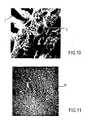
- an external skin designated by H in the diagram of FIG. 7a porous structure comprising macrovides I in the form of elongated fingers open towards the inside, as can be seen more precisely on the photographic enlargement 10.
- This photographic enlargementcorresponds, in fact, to a shooting from inside the fiber.
- the substantially circular craters that can be seen therecorrespond to the ends of these fingers.
- the microvides JAs for the external skin H, this appears on the photographic enlargement 11 which shows the density of this skin without clearly visible voids. Given this structure, it is obvious that the porosity of the fiber is increasing from the outside to the inside.
- a reservoir 1 of polymer solution advantageously provided with a filter 3aadmits this solution into the die 6, shown on a larger scale, under pressure, by virtue of the introduction of an inert gas such as for example nitrogen, supplied by the gas cylinder 2, the control of this pressure being done by the pressure gauge 3.
- the polymer solution from reservoir 1contains a solvent for this polymer and at least one additive as defined above, that is to say either a macromolecule with a molar mass greater than 500, or an ionic surfactant or not. (hydrophilic-hydrophobic).
- the fluid containing the solvent as described aboveis admitted into the annular orifice of this die 6.
- the fluidcomes from a reservoir 4 and its admission into the die is via a flow meter 5 controlling the flow and a valve 8 whose control is a function of the desired flow.
- a motor 9 for winding the fiber 10 downstream of the coagulation tank 7 containing the coagulating solutionmakes it possible both to adjust the drawing tension of the fiber and its storage.
- the coagulation solutioncan be chosen from any suitable non-solvent. It will preferably be water.
- the asymmetry of the hollow fiber according to the inventionis obtained by virtue of a different coagulation of the two faces of the extrudate.
- the external face of the fibercoagulates quickly in contact with the non-solvent for the polymer, while very slow coagulation of the internal face occurs since the latter is in contact with the solvent contained in the fluid injected at the central part of the annular orifice of the font 6.
- this type of spinningis carried out using extrudable solutions capable of forming a solid precursor before viscosities of about 5 pascal-seconds to 1000 pascal-seconds or more, at the spinning temperature.
- non-solvent and the solventmust be miscible and preferably in all proportions and the additive can advantageously be removed from the fiber by simple washing using a solvent thereof which is, of course , non-solvent for the polymer.
- the characterization of the porosityis carried out by observation of images obtained by scanning electron microscopy. If this technique makes it possible to ensure that the skin does not have pores of a dimension greater than 1000 ⁇ (0.1 ⁇ m) approximately, it does not allow to easily and with certainty detect pores of smaller dimension.
- water permeabilitywas used.
- One method of measuring water permeabilityis to form a loop of a few hollow fibers. The open end of the hollow fibers is embedded in a sheet of tubes. This loop is then placed in a cylindrical envelope. Pressurized water is introduced into the envelope and the water which has passed through the wall of the fibers is collected by the open end of the loop.
- the ratio between the quantity of water collected (expressed in m3 per second and per m2 of surface) and the pressure difference applied on either side of the fiber wall (expressed in pascals)is used to calculate the permeability .
- This ratio symbolized by Lpis called the coefficient of hydraulic permeability. Its unit is m3 / m2.s Pa or m / s.Pa. All permeabilities are measured at a temperature of 75 ° C.
- Example 1A solution identical to that of Example 1 is made. This solution is spun by the method described, using a solution of the following type as internal injection fluid:
- a hollow fiberis obtained. Its outside diameter is 350 ⁇ m and its inside diameter is 110 ⁇ m.
- the hollow fibers obtained according to the inventionfind interesting applications in various fields and in particular, they can be directly used in ultrafiltration or in microfiltration, in the field of dialysis, in the field of reverse osmosis, in that of gas permeation or pervaporation, or even as a liquid membrane support.
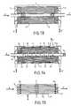
- the cartridge designated by the reference Cconsists of a cylinder 11 containing a bundle 12 of a large number of hollow fibers arranged parallel to each other.
- the ends of these fibersare poured into a block 13-13a of suitable resin and bonded in this block, thus ensuring a seal between the liquid to be "ultrafiltered” admitted through the orifice A, under pressure, to cause this liquid to circulate essentially parallel to the axis of the fibers and outside of them (in the direction AD).
- the permeate, collected in the internal channel of each of the fibersflows out of the cartridge through one or the other or through the two ends of the fibers (arrows B-B ').
- the cartridge illustrated in FIG. 14also consists of a cylinder 11, of a bundle of hollow fibers 12, the ends of which, as before, are embedded and glued in the blocks of resins 13-13a.
- the liquid to be treated (A)is brought to the center of the bundle of fibers by means of a tube 14 pierced with multiple orifices 15, this tube 14 being arranged parallel to the axis of the fibers. It is closed at the end opposite the inlet end of the liquid A, by a removable plug 16.
- the circulation of the liquid Atakes place under pressure and, given the presence of the plug 16, this circulation takes place essentially perpendicular to the axis of the fibers, thanks to the presence of the orifices 15.
- the permeateis collected in the internal channel of the fibers and it flows out of the cartridge by one or the other or by the two ends of the fibers (arrows B-B ').
- the solutionis removed at A ', following the arrows f , a grid of any suitable material (17) providing the desired circulation space between the walls of the cylinder 11 and the bundle of fibers 12.
- FIG. 15illustrates an internal circulation cartridge where, as in the previous case, the bundle of fibers 12 is disposed inside the cylinder 11 with the end of the fibers embedded in the blocks 13 -13a, the liquid A to be treated circulates under pressure, in the direction AD, inside the internal channels of the fibers as illustrated by the arrows F.
- the permeateis collected outside the bundle of fibers and flows out of the cartridge by one or more orifices such as at B, produced at the periphery of the cylinder 11.
- These fibersare characterized, as regards their structure, by the fact that they have on their external face a skin not comprising pores of diameter greater than 1000 ⁇ and that the open structure underlying the external skin is constituted by a microporous layer having pores the largest size of which does not exceed 1.5 ⁇ m and by a macroporous layer having macrovides of cylindrical shape oriented radially and opening onto the internal face; these macrovides have a diameter of around 15 ⁇ m.
- the fibers which equip the CI cartridgeare obtained according to the process described in the publication "Hollow fibers in polysulfone. Preparation and transfer properties in ultrafiltration” published in Account Rendu of the Academy of Sciences Paris, t. 293. series II pp. 681-686 (November 9, 1981). They result from the spinning of a solution composed of 18% polysulfone ("Udel 3500”). 18% polyvinylpyrrolidone "K 15" (Fluka) and 64% N, N-dimethylacetamide. Water is used as an internal coagulation fluid. They are characterized in that they have on their internal face a skin not comprising pores with a diameter greater than 1000 ⁇ and a microporous layer comprising macrovides which do not open onto the external face.
- the circulation rate at the inlet of the cartridgeis 4.6.10 ⁇ 5m3 / s .
- the inlet pressureis 115 kPa and 100 kPa at the outlet of the cartridge, i.e. a pressure drop of 15 kPa.
- the electrical conductivities of the treated solution and of the permeateare measured, and they are found to be identical, thus proving that the fibers allow the saline solution to pass freely.
- the circulation rate (outside the fibers) at the inlet of the cartridgeis 4,6.10 ⁇ 5m3 / s.
- the inlet pressureis 118 kPa, the outlet pressure 100 kPa, i.e. a pressure drop of 18 kPa.
- the ultrafilrat flow rateis 2.3.10 ⁇ 6m3 / s.
- the ultrafiltrate flow rateis 0.51.10 ⁇ 6m3 / s.
- Example 6it is checked that the fibers of the CER cartridge (FIG. 2) that are used, allow an aqueous solution containing 5 g / liter of NaCl to pass freely.
- the ultrafiltrate flow rateis 0.86.10 ⁇ 6 m3 / s.
- the circulation rate (inside the fibers) at the inlet of the cartridgeis 4,6.10 ⁇ 5 m3 / s.
- the inlet pressureis 175 kPa
- the outlet pressureis 100 kPa, i.e. a pressure drop of 75 kPa.
- the ultrafiltrate flow rateis 0.66.10 ⁇ 6m3 / s.
- a 6 g / liter solution of whey proteinis ultrafiltered using the CER cartridge (fig. 2) at a temperature of 25 ° C.
- This solutionis concentrated from 6 g / liter to 30 g / liter, thus passing from an initial volume of 1 liter to a final volume of 0.2 liters.
- the circulation rate (outside the fibers) at the inlet of the cartridgeis 3.10 ⁇ 5 m3 / s.
- the inlet pressureis 108 kPa, and the outlet pressure is 100 kPa, i.e. a pressure drop of 8 kPa.
- the ultrafiltrate flow ratevaries from 1.06.10 ⁇ 6 m3 / s at the start to 0.33.10 ⁇ 6 ⁇ 6 m3 / s at the end of the concentration. This gives an average ultrafiltrate flow rate of 0.53.10 ⁇ 6 m3 / s.
- Skimmed milk(UHT "Candia”) is ultrafiltered using the CER 1 cartridge at a temperature of 50 ° C.
- This milkis concentrated by a factor of 3, passing from an initial volume of 0.9 liters to a final volume of 0.3 liters.
- the circulation flow (external to the fibers) at the inlet of the cartridgeis 2.10 ⁇ 5 m3 / s.
- the inlet pressureis 110 kPa, and 100 kPa at the outlet, i.e. a pressure drop of 10 kPa.
- the ultrafiltrate flow ratevaries from 1.5.10 ⁇ 6m3 / s at the start of concentration to 0.12.10 ⁇ 6m3 / s at the end of the concentration, ie an average ultrafiltrate flow rate of 0.31.10 ⁇ 6m3 / s.
Landscapes
- Engineering & Computer Science (AREA)
- Chemical & Material Sciences (AREA)
- Chemical Kinetics & Catalysis (AREA)
- Textile Engineering (AREA)
- Manufacturing & Machinery (AREA)
- Water Supply & Treatment (AREA)
- Life Sciences & Earth Sciences (AREA)
- Food Science & Technology (AREA)
- Polymers & Plastics (AREA)
- Mechanical Engineering (AREA)
- General Chemical & Material Sciences (AREA)
- Separation Using Semi-Permeable Membranes (AREA)
- Artificial Filaments (AREA)
- Spinning Methods And Devices For Manufacturing Artificial Fibers (AREA)
Abstract
Description
Translated fromFrenchLa présente invention concerne un procédé de préparation de fibres creuses à base de substances polymères fibrogènes.The present invention relates to a process for the preparation of hollow fibers based on fibrogenic polymeric substances.
On connaît déjà un certain nombre de fibres creuses à base de substances polymères fibrogènes présentant des structures asymétriques. De telles structures asymétriques appartiennent, en général, à l'une des classes suivantes :
- la classe des structures présentant une couche relativement dense dite ci-après "peau" à la périphérie du canal interne de la fibre avec, comme caractéristique notable, une porosité croissante (de l'intérieur vers l'extérieur de la fibre) et la présence de macrovides entre cette peau interne et la périphérie externe de la fibre. Une telle fibre est illustrée à la figure 1 (vue en coupe suivant un plan perpendiculaire à l'axe longitudinal de la fibre) des dessins annexés. En se référant à cette figure, on a schématisé en A une portion de la peau interne, en B les macrovides, la référence C désignant la périphérie externe de la fibre et la flèche F symbolisant la porosité croissante de l'intérieur vers l'extérieur de la fibre. Des fibres présentant une telle structure sont par exemple révélées dans les brevets US N° 3.526.588, 3.615.024, 3.423.491 ;
- la classe des structures présentant, comme dans le cas précédent, une peau interne, une porosité croissante de l'intérieur vers l'extérieur de la fibre mais l'absence de macrovides. C'est ainsi que la figure 2 des dessins annexés schématise une fibre de cette classe, A désignant la peau interne, D la section entre cette peau interne et la périphérie C, dans laquelle on remarque l'absence de macrovides et la flèche F symbolisant la porosité croissante de l'intérieur vers l'extérieur de la fibre. De telles fibres sont par exemple révélées dans le brevet US N° 4.051.300 ;
- la classe des structures présentant une peau interne et une peau externe, ces deux peaux se trouvant de part et d'autre d'une section des fibres présentant une majorité de macrovides. Une telle fibre est illustrée à la figure 3 des dessins annexés. On voit sur cette figure en A la peau interne, en E la peau externe et entre les deux, les macrovides B. La porosité dans ce type de fibres est également croissante mais dans le sens des deux flèches F₁ et F₂. Ce type de fibres est par exemple révélé dans le brevet français N° 77.34031 ;
- la classe des structures ne présentant pas, à l'inverse des classes précédemment décrites, de peau interne mais ne présentant par contre qu'une peau externe. De telles fibres ne comportent pas de macrovides entre l'extérieur et l'intérieur de la fibre. Leur porosité est croissante de l'extérieur vers l'intérieur. La figure 4 illustre une telle fibre. On y a schématisé en E la peau externe et en D la couche poreuse, la porosité étant dans ce cas croissante dans le sens de la flèche F₃. De telles fibres ont par exemple été révélées dans le brevet français N° 80.06858 ;
- la classe des structures présentant, comme dans le cas des fibres illustrées à la figure 3, une peau interne et une peau externe mais avec la présence de macrovides entre ces deux peaux. Une telle fibre est illustrée à la figure 5. A et E désignent respectivement les peaux interne et externe avec une certaine proportion de macrovides et de microvides (B et D). Dans ce cas, la porosité est croissante dans le sens des deux flèches F₄ et F₅. De telles fibres sont révélées par exemple dans le brevet français N° 79.11031 ;
- la classe des structures ne présentant aucune peau comme illustré à la figure 6, figure sur laquelle la structure poreuse entre la périphérie interne G et la périphérie externe C comporte à la lois des macro- et des microvides respectivement D et B. Ce type de fibres est révélé par exemple dans le brevet français N° 73.15427.
- the class of structures having a relatively dense layer, hereinafter called "skin", at the periphery of the internal channel of the fiber with, as a notable characteristic, an increasing porosity (from the inside to the outside of the fiber) and the presence macrovides between this inner skin and the outer periphery of the fiber. Such a fiber is illustrated in Figure 1 (sectional view along a plane perpendicular to the longitudinal axis of the fiber) of the accompanying drawings. Referring to this figure, a portion of the internal skin is shown diagrammatically in A, macrovides in B, the reference C designating the external periphery of the fiber and the arrow F symbolizing the increasing porosity from the inside to the outside fiber. Fibers having such a structure are for example disclosed in US Pat. Nos. 3,526,588, 3,615,024, 3,423,491;
- the class of structures having, as in the previous case, an internal skin, increasing porosity from the inside to the outside of the fiber but the absence of macrovides. Thus, Figure 2 of the accompanying drawings shows schematically a fiber of this class, A designating the inner skin, D the section between this inner skin and the periphery C, in which we note the absence of macrovides and the arrow F symbolizing increasing porosity from the inside to the outside of the fiber. Such fibers are for example disclosed in the US Patent No. 4,051,300;
- the class of structures having an inner skin and an outer skin, these two skins being on either side of a section of the fibers having a majority of macrovides. Such a fiber is illustrated in Figure 3 of the accompanying drawings. We see in this figure in A the inner skin, in E the outer skin and in between, the macrovides B. The porosity in this type of fiber is also increasing but in the direction of the two arrows F₁ and F₂. This type of fiber is for example disclosed in French patent N ° 77.34031;
- the class of structures not having, unlike the classes described above, an internal skin but on the other hand only having an external skin. Such fibers do not have macrovides between the outside and the inside of the fiber. Their porosity is increasing from outside to inside. Figure 4 illustrates such a fiber. There is shown diagrammatically in E the outer skin and in D the porous layer, the porosity being in this case increasing in the direction of arrow F₃. Such fibers have, for example, been disclosed in French patent No. 80.06858;
- the class of structures having, as in the case of the fibers illustrated in FIG. 3, an internal skin and an external skin but with the presence of macrovides between these two skins. Such a fiber is illustrated in FIG. 5. A and E respectively designate the inner and outer skins with a certain proportion of macrovides and microvides (B and D). In this case, the porosity is increasing in the direction of the two arrows F₄ and F₅. Such fibers are disclosed for example in French patent No. 79.11031;
- the class of structures exhibiting no skin as illustrated in FIG. 6, a figure in which the porous structure between the internal periphery G and the external periphery C comprises the laws of macro- and microvides respectively D and B. This type of fibers is disclosed, for example, in French Patent No. 73.15427.
La demande de brevet japonais N° 54.10282 décrit des fibres creuses présentant une peau dont les pores ont un diamètre inférieur à 0,05 µm et dont la couche sous-jacente comprend des macrocavités de formes et dimensions variables, de répartition irrégulière et en quantité limitée. Ces fibres ont une perméabilité à l'eau réduite, même par utilisation de polymères hydrophiles et malgré la présence d'un important canal central.Japanese patent application No. 54.10282 describes hollow fibers having a skin whose pores have a diameter of less than 0.05 μm and whose underlying layer comprises macrocavities of variable shapes and dimensions, of irregular distribution and in limited quantity . These fibers have a reduced water permeability, even by using hydrophilic polymers and despite the presence of an important central channel.
La demande de brevet européen N° 0092587 décrit des membranes d'ultrafiltration à base de fibres creuses réalisées en polyméthylméthacrylate et préparées par extrusion d'une solution qui est le siège d'une séparation de phase, avant sa pénétration dans le bain de coagulation et par injection dans le canal d'un solvant pur ou en mélange. Les fibres permettent le passage de macromolécules telles que l'albumine et des protéines sériques.European patent application No. 0092587 describes ultrafiltration membranes based on hollow fibers made of polymethylmethacrylate and prepared by extrusion of a solution which is the site of a phase separation, before its penetration into the coagulation bath and by injection into the solvent channel pure or mixed. The fibers allow the passage of macromolecules such as albumin and serum proteins.
Il serait souhaitable de disposer de fibres creuses alliant une bonne séparation à une bonne perméabilité à l'eau.It would be desirable to have hollow fibers combining good separation with good water permeability.
C'est pourquoi la présente invention a pour objet un procédé selon revendication 1.This is why the present invention relates to a method according to
La présente invention vise des fibres creuses de structure asymétrique se différenciant des diverses structures rappelées ci-dessus en ce sens qu'elles présentent une couche relativement dense ("peau") de très faible épaisseur (< 1µm, et de préférence inférieure à 0,1 µm) à leur périphérie externe, laquelle est liée à une structure dont la porosité augmente lorsqu'on se dirige vers la face interne.The present invention relates to hollow fibers of asymmetrical structure which differ from the various structures mentioned above in that they have a relatively dense layer ("skin") of very small thickness (<1 μm, and preferably less than 0, 1 µm) at their external periphery, which is linked to a structure whose porosity increases when one goes towards the internal face.
De façon particulière,
- la structure sous-jacente à ladite peau est une structure dite "ouverte", composée avantageusement d'une couche microporeuse directement au contact de ladite peau dense et est caractérisée par la présence de pores de dimensions supérieures à 0,1 µm et inférieures à 2 µm et d'une couche macroporeuse présentant des macrovides essentiellement cylindriques orientés radialement et régulièrement espacés avec des parois de porosité homogène dans le sens radial s'ouvrant du côté de la face interne de la fibre et ne s'ouvrant pas du côté de la face externe, ces macrovides ayant une dimension principale supérieure à 2 µm, la proportion de ces macrovides représentant au moins 10 % en volume de la paroi.
- the structure underlying said skin is a so-called "open" structure, advantageously composed of a microporous layer directly in contact with said dense skin and is characterized by the presence of pores of dimensions greater than 0.1 μm and less than 2 µm and of a macroporous layer having essentially cylindrical macrovides oriented radially and regularly spaced with walls of homogeneous porosity in the radial direction opening on the side of the internal face of the fiber and not opening on the side of the face external, these macrovides having a main dimension greater than 2 μm, the proportion of these macrovides representing at least 10% by volume of the wall.
Suivant d'autres caractéristiques :
- ladite peau externe présente une très faible épaisseur inférieure à 0,1 µm et est perméable à l'eau avec une absence substantielle de pores de diamètre supérieur à 0,1 µm ;
- la proportion des macrovides représente au moins 20 % en volume de la paroi ;
- les macrovides sensiblement cylindriques ont une longueur pouvant atteindre plus de 9/10èmes de l'épaisseur de la paroi totale ;
- le diamètre de la section circulaire des macrovides est généralement supérieur à 5 µm ;
- les fibres creuses selon l'invention sont à base de tous polymères fibrogènes pouvant être dissous dans un solvant et coagulés dans un non-solvant.
- said outer skin has a very small thickness of less than 0.1 μm and is permeable to water with a substantial absence of pores with a diameter greater than 0.1 μm;
- the proportion of macrovides represents at least 20% by volume of the wall;
- the substantially cylindrical macrovides have a length which can reach more than 9/10 of the thickness of the total wall;
- the diameter of the circular section of macrovides is generally greater than 5 µm;
- the hollow fibers according to the invention are based on all fibrogenic polymers which can be dissolved in a solvent and coagulated in a non-solvent.
Parmi les exemples de polymères susceptibles de former les fibres selon l'invention, on peut citer les polyfluorures de vinylidène, les polysulfones, les polyacrylonitriles, la cellulose et les esters cellulosiques, les poly(chlorures de vinyle), les poly(acétates de vinyle), les polyamides, les polyimides, les polycarbonates, les poly(oxydes de phénylène), les polystyrènes et plus généralement, les polyéthers, les polyesters, les poly(oxydes d'aryline), les polysullures, les polymères polyvinyliques, les polymères polyallyliques, les polyazoles et les polyimidazoles, les polyphosphazines, les polyhydrazides, ou bien ce polymère fibrogène peut être choisi parmi les copolymères ou les mélanges de polymères constitués à partir d'au moins un des polymères ci-dessus.Among the examples of polymers capable of forming the fibers according to the invention, mention may be made of polyvinylidene fluorides, polysulfones, polyacrylonitriles, cellulose and cellulose esters, poly (vinyl chlorides), poly (vinyl acetates) ), polyamides, polyimides, polycarbonates, poly (phenylene oxides), polystyrenes and more generally, polyethers, polyesters, poly (aryl oxides), polysullides, polyvinyl polymers, polyallylic polymers , polyazoles and polyimidazoles, polyphosphazines, polyhydrazides, or this fibrogenic polymer can be chosen from copolymers or mixtures of polymers made from at least one of the above polymers.
On obtient les fibres en question en mettant en oeuvre le procédé décrit précédemment.The fibers in question are obtained by implementing the method described above.
L'additif particulier est choisi parmi les molécules permettant l'obtention d'une solution macroscopiquement homogène avec le couple solvant-polymère, tout en étant susceptible d'être extrait de la fibre lors de la coagulation de cette dernière, ou par tout post-traitement approprié. Comme exemple de molécules d'additif répondant à la définition ci-dessus, on peut citer soit des macromolécules de masse moléculaire supérieure à 500, du type polyvinylpyrrolidones, polyvinylpyridines, alcools polyvinyliques, polyéthylèneglycols, polyacryamides, acides polyacryliques, soit des agents tensio-actifs ioniques ou non, comprenant dans leur molécule, à la fois au moins un motif hydrophobe et au moins un motif hydrophile (ionique ou non), le motif hydrophobe pouvant être du type polyoxyéthylène.The particular additive is chosen from molecules which make it possible to obtain a macroscopically homogeneous solution with the solvent-polymer couple, while being capable of being extracted from the fiber during the coagulation of the latter, or by any post- appropriate treatment. As an example of additive molecules meeting the above definition, there may be mentioned either macromolecules of molecular mass greater than 500, of the polyvinylpyrrolidones, polyvinylpyridines, polyvinyl alcohols, polyethylene glycols, polyacryamides, polyacrylic acids, or surfactants ionic or not, comprising in their molecule, both at least one hydrophobic unit and at least one hydrophilic unit (ionic or not), the hydrophobic unit possibly being of the polyoxyethylene type.
Le fluide particulier d'injection interne peut être un liquide ou un gaz et il contient une quantité suffisante d'au moins un solvant du polymère fibrogène pour éviter que ledit fluide ne coagule la solution contenant le polymère fibrogène.The particular internal injection fluid may be a liquid or a gas and it contains a sufficient quantity of at least one solvent for the fibrogenic polymer to prevent said fluid from coagulating the solution containing the fibrogenic polymer.
La portée et l'intérêt de l'invention ressortiront plus clairement de la description qui va suivre, faite en regard des dessins annexés sur lesquels :
- les figures 1 à 6 qui ont déjà été décrites illustrent différents types de fibres connues ;
- la figure 7 est une figure schématique établie sur les mêmes bases que ces figures 1 à 6 illustrant la section d'une fibre obtenue selon l'invention ;
- les figures 8, 9, 10 et 11 sont différentes vues photographiques prises au microscope électronique d'une fibre obtenue selon l'invention, et,
- la figure 12 est un schéma explicatif du procédé selon invention.
- la figure 13 illustre un mode de réalisation possible d'une cartouche mettant en oeuvre des faisceaux de fibres à circulation externe longitudinale (CEL) ;
- la figure 14 illustre un autre mode de réalisation possible d'une cartouche mettant en oeuvre des faisceaux de fibres à circulation externe radiale (CER) ;
- la figure 15 illustre un troisième mode de réalisation possible mettant en oeuvre des faisceaux de fibres à circulation interne (CI).
- Figures 1 to 6 which have already been described illustrate different types of known fibers;
- Figure 7 is a schematic figure established on the same bases as these Figures 1 to 6 illustrating the section of a fiber obtained according to the invention;
- FIGS. 8, 9, 10 and 11 are different photographic views taken with an electron microscope of a fiber obtained according to the invention, and,
- FIG. 12 is an explanatory diagram of the method according to the invention.
- FIG. 13 illustrates a possible embodiment of a cartridge using bundles of fibers with longitudinal external circulation (CEL);
- FIG. 14 illustrates another possible embodiment of a cartridge using bundles of fibers with radial external circulation (CER);
- FIG. 15 illustrates a third possible embodiment using bundles of fibers with internal circulation (CI).
En se référant à ces figures, on voit, en particulier sur les agrandissements photographiqees 8 et 9 (coupes axiales), une peau externe désignée par H sur le schéma de la figure 7 ; une structure poreuse comportant des macrovides I en forme de doigts allongés ouverts vers l'intérieur, comme on le voit plus précisément sur l'agrandissement photographique 10. Cet agrandissement photographique correspond, en effet, à une prise de vue depuis l'intérieur de la fibre. Les cratères sensiblement circulaires que l'on y distingue correspondent à l'éxtrémité de ces doigts. On distingue aussi sur cet agrandissement les microvides J. Quant à la peau externe H, celle-ci apparait sur l'agrandissement photographique 11 qui montre la densité de cette peau sans vides nettement visibles. Compte tenu de cette structure, il est manifeste que la porosité de la fibre est croissante de l'extérieur vers l'intérieur.Referring to these figures, we can see, in particular on the photographic enlargements 8 and 9 (axial sections), an external skin designated by H in the diagram of FIG. 7; a porous structure comprising macrovides I in the form of elongated fingers open towards the inside, as can be seen more precisely on the
Pour plus de précisions, il est à noter que dans l'agrandissenent photographique 8, 1 cm = 50 µm ; dans l'agrandissement 9, 1,5 cm = 25 µm ; dans l'agrandissement 10, 1 cm = 5 µm et dans l'agrandissement 11, 1 cm = 1 µm.For more details, it should be noted that in the
Pour obtenir les fibres creuses ainsi illustrées, on fait appel à la technique de filage dite "par voie sèchehumide". Cette technique est représentée schématiquement sur la figure 12.To obtain the hollow fibers thus illustrated, use is made of the so-called "dry-wet" spinning technique. This technique is shown schematically in Figure 12.
Un réservoir 1 de solution de polymère avantageusement muni d'un filtre 3a admet cette solution dans la filière 6, représentée à plus grande échelle, sous pression, grâce à l'introduction d'un gaz inerte comme par exemple de l'azote, fourni par la bouteille de gaz 2, le contrôle de cette pression se faisant par le manomètre 3. La solution de polymère provenant du réservoir 1 renferme un solvant de ce polymère et au moins un additif tel que défini précédemment, c'est-à-dire soit une macromolécule de masse molaire supérieure à 500, soit un agent tensio-actif ionique ou non (hydrophile-hydrophobe).A
Concomitamment, on admet dans l'orifice annulaire de cette filière 6 le fluide contenant le solvant tel que décrit précédemment. Bien entendu, le fluide provient d'un réservoir 4 et son admission dans la filière se fait par l'intermédiaire d'un débitmètre 5 contrôlant le débit et d'une vanne 8 dont la commande est fonction du débit désiré. Un moteur 9 de bobinage de la fibre 10 en aval du bac de coagulation 7 contenant la solution coagulante permet à la fois de régler la tension d'étirage de la fibre et son stockage.Concomitantly, the fluid containing the solvent as described above is admitted into the annular orifice of this die 6. Of course, the fluid comes from a
La solution de coagulation peut être choisie parmi tous non-solvants appropriés. Ce sera de préférence de l'eau.The coagulation solution can be chosen from any suitable non-solvent. It will preferably be water.
En procédant de la sorte, l'asymétrie de la fibre creuse selon l'invention est obtenue grâce à une coagulation différente des deux faces de l'extrudat. La face externe de la fibre se coagule rapidement au contact du non-solvant du polymère, alors que se produit une très lente coagulation de la face interne puisque celle-ci est en contact avec le solvant contenu dans le fluide injecté à la partie centrale de l'orifice annulaire de la fitière 6.By proceeding in this way, the asymmetry of the hollow fiber according to the invention is obtained by virtue of a different coagulation of the two faces of the extrudate. The external face of the fiber coagulates quickly in contact with the non-solvent for the polymer, while very slow coagulation of the internal face occurs since the latter is in contact with the solvent contained in the fluid injected at the central part of the annular orifice of the font 6.
De façon avantageuse, ce type de filage est réalisé en faisant appel à des solutions extrudables capables de former un solide précurseur avant des viscosités d'environ 5 pascal-seconde à 1000 pascal-seconde ou plus, à la température de filage.Advantageously, this type of spinning is carried out using extrudable solutions capable of forming a solid precursor before viscosities of about 5 pascal-seconds to 1000 pascal-seconds or more, at the spinning temperature.
De plus, le non-solvant et le solvant doivent être miscibles et de préférence en toutes proportions et l'additif peut avantageusement être éliminé de la fibre par simple lavage à l'aide d'un solvant de celui-ci qui soit, bien entendu, non solvant du polymère.In addition, the non-solvent and the solvent must be miscible and preferably in all proportions and the additive can advantageously be removed from the fiber by simple washing using a solvent thereof which is, of course , non-solvent for the polymer.
Il va de soi que plus le non-solvant du polymère sera fort, plus l'asymétrie sera importante et plus, le temps de coagulation total avant lavage et stockage sera faible.It goes without saying that the stronger the non-solvent of the polymer, the greater the asymmetry and the longer, the total coagulation time before washing and storage will be short.
Dans les examples qui suivent, la caractérisation de la porosité est effectuée par observation de clichés obtenus par microscopie électronique à balayage. Si cette technique permet de s'assurer que la peau ne comporte pas de pores d'une dimension supérieure à 1000 Å (0,1 µm) environ, elle ne permet pas de détecter facilement et avec certitude des pores de plus faible dimension. Pour vérifier la présence de pores plus fins, la perméabilité à l'eau a été utilisée. Un procédé pour mesurer la perméabilité à l'eau consiste à former une boucle de quelques fibres creuses. L'extrémité ouverte des fibres creuses est encastrée dans une feuille de tubes. Cette boucle est ensuite placée dans une enveloppe cylindrique. De l'eau sous pression est introduite dans l'enveloppe et l'on recueille l'eau qui a traversé la paroi des fibres par l'extrémité ouverte de la boucle.In the examples which follow, the characterization of the porosity is carried out by observation of images obtained by scanning electron microscopy. If this technique makes it possible to ensure that the skin does not have pores of a dimension greater than 1000 Å (0.1 µm) approximately, it does not allow to easily and with certainty detect pores of smaller dimension. To check for the presence of finer pores, water permeability was used. One method of measuring water permeability is to form a loop of a few hollow fibers. The open end of the hollow fibers is embedded in a sheet of tubes. This loop is then placed in a cylindrical envelope. Pressurized water is introduced into the envelope and the water which has passed through the wall of the fibers is collected by the open end of the loop.
Le rapport entre la quantité d'eau recueillie (exprimée en m³ par seconde et par m² de surface) et la différence de pression appliquée de part et d'autre de la paroi de la fibre (exprimée en pascals) est utilisé pour chiffrer la perméabilité. Ce rapport symbolisé par Lp est appelé coefficient de perméabilité hydraulique. Il a comme unité des m³/m².s Pa ou des m/s.Pa. Toutes les perméabilités sont mesurées à la température de 75°C.The ratio between the quantity of water collected (expressed in m³ per second and per m² of surface) and the pressure difference applied on either side of the fiber wall (expressed in pascals) is used to calculate the permeability . This ratio symbolized by Lp is called the coefficient of hydraulic permeability. Its unit is m³ / m².s Pa or m / s.Pa. All permeabilities are measured at a temperature of 75 ° C.
A partir d'une solution composée de polysulfone ("Udel 3500") à 29 %, de "Triton X 100" à 22 % et de N-N-diméthylformamide à 49 % (% massique), on a extrudé avec la méthode décrite, et avèc du N-N-diméthylformamide comme fluide d'injection interne et de l'eau comme coagulant, une fibre creuse.From a solution composed of polysulfone ("Udel 3500") at 29%, "Triton X 100" at 22% and NN-dimethylformamide at 49% (mass%), it was extruded with the method described, and with NN-dimethylformamide as an internal injection fluid and water as a coagulant, a hollow fiber.
Son diamètre extérieur est de 580 µm et son diamètre intérieur de 440 µm.Its outside diameter is 580 µm and its inside diameter is 440 µm.
La fibre creuse présente la structure selon l'invention :
- sur sa face externe, on trouve une "peau" ne comportant pas de pores de diamètre supérieur à 1000 Å ;
- la structure ouverte sous-jacente à la peau externe est constitutée par une couche microporeuse d'épaisseur 30 µm présentant des pores dont la plus grande taille est d'environ 1,5 µm, et d'une couche macroporeuse présentant des macrovides de forme cylindrique orientés radialement débouchant sur la face interne ayant 40 µm environ de longueur et un diamètre sur la face interne d'environ 14 µm. Ces macrovides en occupent environ 20 % du volume de la paroi.
- on its external face, there is a "skin" having no pores with a diameter greater than 1000 Å;
- the open structure underlying the external skin is constituted by a microporous layer 30 μm thick having pores the largest size of which is approximately 1.5 μm, and by a macroporous layer presenting macrovides of cylindrical shape oriented radially opening onto the internal face having approximately 40 μm in length and a diameter on the internal face of approximately 14 μm. These macrovides occupy about 20% of the volume of the wall.
La présence de pores de diamètre inférieur à 1000 Å dans la peau est mise en évidence par la perméabilité à l'eau :
A partir d'une solution composée de polyfluorure de vinylidène ("FUCK 1000") à 28%, "Triton X100" à 18 %et de N-N-diméthylformamide à 54 % (% massique), avec comme fluide d'injection interne du N-N-diméthyl acétamide, et de l'eau comme coagulant, on a filé une fibre creuse. Son diamètre extérieur est de 580 µm et son diamètre intérieur de 440 µm.From a solution composed of polyvinylidene fluoride ("FUCK 1000") at 28%, "Triton X100" at 18% and NN-dimethylformamide at 54% (mass%), with NN as internal injection fluid -dimethyl acetamide, and water as a coagulant, a hollow fiber was spun. Its outside diameter is 580 µm and its inside diameter is 440 µm.
La fibre creuse présente la structure selon l'invention :
- sur sa face externe on trouve une peau ne comportant pas de pores de diamètre supérieur à 1000 Å ;
- la structure ouverte sous-jacente à la peau externe est constituée d'une couche microporeuse d'épaisseur 4 µm présentant des pores dont la plus grande taille est d'environ 0,5 µm, et d'une couche macroporeuse présentant des macrovides de forme cylindrique orientés radialement et débouchant sur la face interne ayant environ 121 µm de longueur et 15 µm de diamètre sur la face interne. Les macrovides occupent environ 40 % du volume de la paroi.
- on its outer face there is a skin having no pores of diameter greater than 1000 Å;
- the open structure underlying the external skin consists of a
microporous layer 4 μm thick having pores the largest size of which is approximately 0.5 μm, and a macroporous layer presenting macrovides of shape cylindrical oriented radially and opening on the internal face having approximately 121 µm in length and 15 µm in diameter on the internal face. Macrovides occupy about 40% of the volume of the wall.
La présence de pores de diamètre inférieur à 1000 Å dans la peau externe est mise en évidence par la perméabilité à l'eau :
A partir d'une solution composée de polysulfone ("Udel 3500") à 18 % de polyvinylpyrrolidone "K15" à 18 % et de N-N-diméthylformamide à 64 % (% massique), avec comme fluide d'injection interne du N-N-diméthylformamide et de l'eau comme coagulant, on a filé une fibre creuse. Son diamètre extérieur est de 430 µm et son diamètre intérieur de 150 µm.From a solution composed of polysulfone ("Udel 3500") at 18%, polyvinylpyrrolidone "K15" at 18% and NN-dimethylformamide at 64% (mass%), with NN-dimethylformamide as internal injection fluid and water as a coagulant, we spun a hollow fiber. Its outside diameter is 430 µm and its inside diameter is 150 µm.
La fibre creuse présente la structure selon l'invention :
- sur sa face externe, on trouve une peau ne comportant pas de pores de diamètre supérieur à 1000 Å ;
- la structure ouverte sous-jacente à la peau externe est constituée d'une couche microporeuse d'épaisseur 20 µm présentant des pores dont la plus grande taille est d'environ 1 µm et d'une couche macroporeuse présentant des macrovides de forme cylindrique orientés radialement et débouchant sur la face interne ayant environ 120 µm de longueur et 10 µm de diamètre, sur la face interne. Les macrovides occupent environ 60 % du volume de la paroi.
- on its outer face, there is a skin having no pores with a diameter greater than 1000 Å;
- the open structure underlying the outer skin consists of a microporous layer 20 μm thick with pores the largest size of which is approximately 1 μm and a macroporous layer with macrovides of cylindrical shape oriented radially and opening onto the internal face having approximately 120 μm in length and 10 μm in diameter, on the internal face. Macrovides occupy about 60% of the volume of the wall.
La présence de pores de diamètre inférieur à 1000 Å dans la peau externe est mise en évidence par la perméabilité à l'eau :
Filage sans apport d'additifSpinning without additive
On fait une solution à 29 % de polysulfone ("Udel 3500") et de 71 % de N-N-diméthylformamide.A 29% solution of polysulfone ("Udel 3500") and 71% of N-N-dimethylformamide is made.
On file cette solution par le procédé décrit en utilisant du N-N-diméthylformamide comme fluide d'injection interne. On constate à l'examen de la fibre obtenue qu'elle comporte une peau externe et une structure sous-jacente ouverte avec la présence de macrovides dont certains s'ouvrent sur la face interne. Cependant une des caractéristiques de cette fibre filée en l'absence d'additif est que sa perméabilité à l'eau est extrêmement faible, ce qui montre ainsi que la peau présente très peu de pores :
Filage en présence d'eau dans le fluide d'injection interneSpinning in the presence of water in the internal injection fluid
On fait une solution identique à celle de l'exemple 1. On file cette solution par le Procédé décrit en utilisant une solution du type suivant comme fluide d'injection interne :
On obtient une fibre creuse. Son diamètre extérieur est de 350 µm et son diamètre intérieur de 110 µm.A hollow fiber is obtained. Its outside diameter is 350 µm and its inside diameter is 110 µm.
La fibre creuse présente la structure selon l'invention :
- sur sa face externe, on trouve une peau ne comportant pas de pores de diamètre supérieur à 1000 Å ;
- la structure ouverte sous-jacente à la peau externe est constituée d'une couche microporeuse d'épaisseur 7 µm présentant des pores dont la plus grande taille est environ 1.5 µm et d'une couche macroporeuse présentant des macrovides de forme cylindrique orientés radialement ayant environ 107 µm de longeur. Les macrovides occupent environ 40 % du volume de la paroi..
- on its outer face, there is a skin having no pores with a diameter greater than 1000 Å;
- the open structure underlying the external skin consists of a microporous layer of thickness 7 μm having pores of which the largest size is approximately 1.5 μm and of a macroporous layer having macrovides of cylindrical shape oriented radially having approximately 107 µm in length. Macrovides occupy about 40% of the volume of the wall.
Une des caractéristiques de ces fibres filées avec la présence de 10 % d'eau dans le fluide d'injection interne est que les macrovides qui ont environ 16 µm de diamètre dans la paroi se rétrécissent pour n'avoir plus que 2 µm de diamètre quand ils débouchent sur la face interne.One of the characteristics of these spun fibers with the presence of 10% of water in the internal injection fluid is that the macrovides which are about 16 µm in diameter in the wall shrink to be only 2 µm in diameter when they lead to the internal face.
La présence de pores de diamètre inférieur à 1000 Å dans la peau externe est mise en évidence par la perméabilité à l'eau :
The presence of pores with a diameter of less than 1000 Å in the external skin is demonstrated by the water permeability:
Les fibres creuses obtenues selon l'invention trouvent des applications intéressantes dans divers domaines et en particulier, elles peuvent être directement utilisées en ultrafiltration ou en microfiltration, dans le domaine de la dialyse, dans le domaine de l'osmose inverse, dans celui de la perméation gazeuse ou de pervaporation, ou même comme support de membrane liquide.The hollow fibers obtained according to the invention find interesting applications in various fields and in particular, they can be directly used in ultrafiltration or in microfiltration, in the field of dialysis, in the field of reverse osmosis, in that of gas permeation or pervaporation, or even as a liquid membrane support.
La présence d'une peau externe dans la structure des fibres obtenues selon l'invention permet leur utilisation en ultrafiltration ou microfiltration dans des systèmes où le fluide à traiter circulera avantageusement à l'extérieur des fibres, rendant ainsi ces systèmes compacta et performants, comme le montrent les exemples qui en sont donnés ci-après :
En Se référant à la figure 13, la cartouche désignée par la référence C se compose d'un cylindre 11 contenant un faisceau 12 d'un grand nombre de fibres creuses disposées parallèlement les unes aux autres. Las extrémités de ces fibres sont coulées dans un bloc 13-13a de résine appropriée et collées dans ce bloc, assurant ainsi une étanchéité entre le liquide à "ultrafiltrer" admis par l'orifice A, sous pression, pour amener ce liquide à circuler essentiellement parallèlement à l'axe des fibres et à l'extérieur de celles-ci (dans le sens A-D). La perméat, recueilli dans le canal interne de chacune des fibres, s'écoule hors de la cartouche par l'une ou l'autre ou par les deux extrémités des fibres (flèches B-B').The presence of an outer skin in the structure of the fibers obtained according to the invention allows their use in ultrafiltration or microfiltration in systems where the fluid to be treated will advantageously circulate outside the fibers, thus making these systems compact and efficient, such as The examples shown below show this:
Referring to Figure 13, the cartridge designated by the reference C consists of a
La cartouche illustrée à la figure 14 est constituée également d'un cylindre 11, d'un faisceau de fibres creuses 12 dont les extrémités sont, comme précédemment, noyées et collées dans les blocs de résines 13-13a. Le liquide à traiter (A) est amené au centre du faisceau de fibres au moyen d'un tube 14 percé d'orifices multiples 15, ce tube 14 étant disposé parallèlement à l'axe des fibres. Il est obturé à l'extrémité opposée à l'extrémité d'entrée du liquide A, par un bouchon amovible 16. La circulation du liquide A s'effectue sous pression et, étant donné la présence du bouchon 16, cette circulation s'effectue essentiellement perpendiculairement à l'axe des fibres, grâce à la présence des orifices 15. Le perméat est recueilli dans le canal interne des fibres et il s'écoule hors de la cartouche par l'une ou l'autre ou par les deux extrémités des fibres (flècnes B-B'). La sortie de la solution s'effectue en A', en suivant les flèchesf, une grille en tout matériau approprié (17) ménageant l'espace de circulation désiré entre les parois du cylindre 11 et le faisceau de fibres 12.The cartridge illustrated in FIG. 14 also consists of a
Par contre, en se référant à la figure 15 qui illustre une cartouche à circulation interne où, comme dans le cas précédent, le faisceau de fibres 12 est disposé à l'intérieur du cylindre 11 avec l'extrémité des fibres noyée dans les blocs 13-13a, le liquide A à traiter circule sous pression, dans le sens A-D, à l'intérieur des canaux internes des fibres comme illustré par les flèches F. Le perméat est recueilli à l'extérieur du faisceau de fibres et circule hors de la cartouche par un ou plusieurs orifices tels que en B, réalisés à la périphérie du cylindre 11.On the other hand, with reference to FIG. 15 which illustrates an internal circulation cartridge where, as in the previous case, the bundle of
Les exemples qui suivent ont pour but de comparer les performances que l'on obtient avec une cartouche contenant des fibres creuses à peau interne (où la circulation du milieu à traiter se fait à l'intérieur des fibres creuses avec une cartouche réalisée telle qu'illustrée à la figure 15) de même encombrement que les cartouches réalisées selon les figures 13 et 14.The examples which follow are intended to compare the performances which one obtains with a cartridge containing hollow fibers with internal skin (where the circulation of the medium to be treated takes place inside the hollow fibers with a cartridge produced such that illustrated in FIG. 15) of the same size as the cartridges produced according to FIGS. 13 and 14.
Les fibres qui équipent les cartouches (CEL et CER) telles qu'illustrées aux figures 13 et 14 ont été obtenues par le procédé décrit ci-dessus.The fibers which equip the cartridges (CEL and CER) as illustrated in FIGS. 13 and 14 were obtained by the process described above.
Il résulte de la filature d'une solution composée de 29 % de polysulfone ("Udel 500"), 22 % de "Triton X 100" et de 49 % de N,N-diméthylformamide, (ces pourcentages étant en % massique), le fluide d'injection interne était du N,N-diméthylformamide, de l'eau ayant été utilisée pour coaguler la face externe de la fibre creuse. Ces fibres sont caractérisées, en ce qui concerne leur structure, par le fait qu'elles présentent sur leur face externe une peau ne comportant pas de pores de diamètre supérieur à 1000 Å et que la structure ouverte sous-jacente à la peau externe est constituée par une couche microporeuse présentant des pores dont la plus grande taille ne dépasse pas 1,5 µm et d'une couche macroporeuse présentant des macrovides de forme cylindrique orientés radialement et débouchant sur la face interne ; ces macrovides ont un diamètre d'environ 15 µm.It results from the spinning of a solution composed of 29% of polysulfone ("Udel 500"), 22% of "Triton X 100" and 49% of N, N-dimethylformamide, (these percentages being in% by mass), the internal injection fluid was N, N-dimethylformamide, water having been used to coagulate the external face of the hollow fiber. These fibers are characterized, as regards their structure, by the fact that they have on their external face a skin not comprising pores of diameter greater than 1000 Å and that the open structure underlying the external skin is constituted by a microporous layer having pores the largest size of which does not exceed 1.5 μm and by a macroporous layer having macrovides of cylindrical shape oriented radially and opening onto the internal face; these macrovides have a diameter of around 15 µm.
Les fibres qui équipent la cartouche CI (figure 15) sont obtenues selon le procédé décrit dans la publication "Fibres creuses en polysulfone. Préparation et propriétés de transfert en ultrafiltration" parue dans Compte Rendu de l'Académie des Sciences Paris, t. 293. série II pp. 681-686 (9 novembre 1981). Elles résultent de la filature d'une solution composée de 18 % de polysulfone ("Udel 3500"). 18 % de polyvinylpyrrolidone "K 15" (Fluka) et de 64 % de N,N-diméthylacétamide. L'eau est utilisée comme fluide de coagulation interne. Elles sont caractérisées en ce qu'elles présentent sur leur face interne une peau ne comportant pas de pores de diamètre supérieur à 1000 Å et une couche microporeuse comportant des macrovides ne débouchant pas sur la face externe.The fibers which equip the CI cartridge (FIG. 15) are obtained according to the process described in the publication "Hollow fibers in polysulfone. Preparation and transfer properties in ultrafiltration" published in Account Rendu of the Academy of Sciences Paris, t. 293. series II pp. 681-686 (November 9, 1981). They result from the spinning of a solution composed of 18% polysulfone ("Udel 3500"). 18% polyvinylpyrrolidone "
Les caractéristiques des cartouches citées dans les exemples ci-après sont résumées dans le tableau 1.The characteristics of the cartridges cited in the examples below are summarized in Table 1.
On ultrafiltre à l'aide de la cartouche CEL (fig.13) une solution aqueuse de NaCl à 5 g/l à 25° C. Le débit de circulation à l'entrée de la cartouche est de 4,6.10⁻⁵m³/s. La pression à l'entrée est de 115 kPa et de 100 kPa à la sortie de la cartouche, soit une perte de charge de 15 kPa.Using the CEL cartridge, ultrafilter an aqueous NaCl solution at 5 g / l at 25 ° C. The circulation rate at the inlet of the cartridge is 4.6.10⁻⁵m³ / s . The inlet pressure is 115 kPa and 100 kPa at the outlet of the cartridge, i.e. a pressure drop of 15 kPa.
On mesure les conductivités électriques de la solution traitée et du perméat, et on constate qu'elles sont identiques, prouvant ainsi que les fibres laissent passer librement la solution saline.The electrical conductivities of the treated solution and of the permeate are measured, and they are found to be identical, thus proving that the fibers allow the saline solution to pass freely.
On ultrafiltre alors à l'aide de la cartouche CEL (fig. 13) une solution à 10 g/l de "Dextran T70" de masse molaire moyenne
Le débit de circulation (extérieur aux fibres) à l'entrée de la cartouche est de 4,6.10⁻⁵m³/s. La pression d'entrée est de 118 kPa, la pression de sortie de 100 kPa, soit une perte de charge de 18 kPa.The circulation rate (outside the fibers) at the inlet of the cartridge is 4,6.10⁻⁵m³ / s. The inlet pressure is 118 kPa, the outlet pressure 100 kPa, i.e. a pressure drop of 18 kPa.
Le débit d'ultrafilrat est de 2,3.10⁻⁶m³/s.The ultrafilrat flow rate is 2.3.10⁻⁶m³ / s.
Lorsqu'on utilise pour ultrafiltrer la même solution que précédemment, la cartouche CI contenant des fibres creuses à peau interne retenant totalement le "Dextran T70", avec un débit de circulation de 4,6.10⁻⁵m³/s, la pression d'entrée est de 126 kPa, la pression de sortie de 100 kPa, soit une perte de charge de 26 kPa.When the same solution as before is used for ultrafiltration, the CI cartridge containing hollow fibers with internal skin totally retaining the "Dextran T70", with a circulation rate of 4.6.10⁻⁵m³ / s, the inlet pressure is of 126 kPa, the outlet pressure of 100 kPa, i.e. a pressure drop of 26 kPa.
Le débit d'ultrafiltrat est de 0,51.10⁻⁶m³/s.The ultrafiltrate flow rate is 0.51.10⁻⁶m³ / s.
La puissance nécessaire pour faire circuler le fluide dans la cartouche est égale au produit du débit de circulation par la perte de charge, soit :
- 0,83 watt pour la cartouche CEL
- 1,2 watt pour la cartouche CI.
- 0.83 watt for the CEL cartridge
- 1.2 watt for the CI cartridge.
L'énergie dépensée par unité de volume d'ultrafiltrat est égale à la puissance nécessaire 3 la circulation divisée par le débit d'ultrafiltrat, soit
- 0,10 kWh/m³ (3,6.10 joules/m³)pour la cartouche CEL
- 0,65 kWh/m³ (23,5.10 joules/m³) pour la cartouche CI.
- 0.10 kWh / m³ (3.6.10 joules / m³) for the CEL cartridge
- 0.65 kWh / m³ (23.5.10 joules / m³) for the CI cartridge.
On remarque un débit d'ultrafiltrat plus élevé et une plus faible consommation d'énergie par unité de volume d'ultrafiltrat pour la cartouche CEL, que pour la cartouche CI.There is a higher ultrafiltrate flow rate and a lower energy consumption per unit volume of ultrafiltrate for the CEL cartridge, than for the CI cartridge.
Comme dans l'exemple 6, on vérifie que les fibres de la cartouche CER (fig. 2) que l'on utilise, laissent passer librement une solution aqueuse à 5 g/litre de NaCl.As in Example 6, it is checked that the fibers of the CER cartridge (FIG. 2) that are used, allow an aqueous solution containing 5 g / liter of NaCl to pass freely.
On ultrafiltre à l'aide de la cartouche CER à 25°C, une solution à 10 g/litre de polyvinylpyrrolidone (PVP)K90 de masse molaire moyenne
Le débit d'ultrafiltrat est de 0,86.10⁻⁶ m³/s.The ultrafiltrate flow rate is 0.86.10⁻⁶ m³ / s.
On utilise pour ultrafiltrer la même solution que précédemment, la cartouche CI contenant des fibres à peau interne qui retiennent totalement la polyvinylpyrrolidone "K90". Le débit de circulation (intérieur aux aux fibres) à l'entrée de la cartouche est de 4,6.10⁻⁵ m³/s. La pression d'entrée est de 175 kPa, la pression de sortie est de 100 kPa, soit une perte de charge de 75 kPa.The same solution as above is used for ultrafiltration, the CI cartridge containing fibers with internal skin which completely retain the polyvinylpyrrolidone "K90". The circulation rate (inside the fibers) at the inlet of the cartridge is 4,6.10⁻⁵ m³ / s. The inlet pressure is 175 kPa, the outlet pressure is 100 kPa, i.e. a pressure drop of 75 kPa.
Le débit d'ultrafiltrat est de 0,66.10⁻⁶m³/s.The ultrafiltrate flow rate is 0.66.10⁻⁶m³ / s.
Comme dans l'exemple 1, on calcule la puissance nécessaire à la circulation de la solution traitée dans la cartouche et l'énergie dépensée par unité de volume d'ultrafiltrat.
Puissance :
- 1,1 watt pour la cartouche CER
- 3,4 watts pour la cartouche CI
- 0,36 kWh/m³ (1,28.10⁶ joules/m³) pour la cartouche CER
- 1,43 kWh/m³ (5,15.10⁶ joules/m³) pour la cartouche CI.
Power :
- 1.1 watt for CER cartridge
- 3.4 watts for the CI cartridge
- 0.36 kWh / m³ (1.28.10⁶ joules / m³) for the CER cartridge
- 1.43 kWh / m³ (5.15.10⁶ joules / m³) for the CI cartridge.
On remarque un débit d'ultrafiltrat plus élevé et une plus faible consommation d'énergie par unité de volume d'ultrafiltrat pour la cartouche CER , que pour la cartouche CI.There is a higher ultrafiltrate flow rate and a lower energy consumption per unit volume of ultrafiltrate for the CER cartridge, than for the CI cartridge.
On ultrafiltre une solution à 6 g/litre de protéines de lactosérum à l'aide de la cartoucne CER (fig. 2) à la température de 25° C.A 6 g / liter solution of whey protein is ultrafiltered using the CER cartridge (fig. 2) at a temperature of 25 ° C.
L'analyse de l'ultrafiltrat montre que les protéines sont totalement retenues par les fibres.Analysis of the ultrafiltrate shows that the proteins are completely retained by the fibers.
On concentre cette solution de 6 g/litre à 30 g/litre en passant ainsi d'un volume initial de 1 litre à un volume final de 0,2 litre. Le débit de circulation (extérieur aux fibres) à l'entrée de la cartouche est de 3.10⁻⁵ m³/s. La pression à l'entrée est de 108 kPa, et la pression à la sortie de 100 kPa, soit une perte de charge de 8 kPa.This solution is concentrated from 6 g / liter to 30 g / liter, thus passing from an initial volume of 1 liter to a final volume of 0.2 liters. The circulation rate (outside the fibers) at the inlet of the cartridge is 3.10⁻⁵ m³ / s. The inlet pressure is 108 kPa, and the outlet pressure is 100 kPa, i.e. a pressure drop of 8 kPa.
Le débit d'ultrafiltrat varie de 1,06.10⁻⁶ m³/s au départ à 0,33.10⁻⁶ m³/s à la fin de la concentration. Ce qui donne un débit moyen d'ultrafiltrat de 0,53.10⁻⁶ m³/s. On calcule comme dans l'exemple 1 la puissance nécessaire à la circulation et l'énergie consommée par unité de volume d'ultrafiltrat.
Puissance :
0,24 watt
Energie :
0,13 kWh/m³ (0,45.10⁶ joules/m³).The ultrafiltrate flow rate varies from 1.06.10⁻⁶ m³ / s at the start to 0.33.10⁻⁶⁻⁶ m³ / s at the end of the concentration. This gives an average ultrafiltrate flow rate of 0.53.10⁻⁶ m³ / s. The power required for circulation and the energy consumed per unit of volume of ultrafiltrate.
Power :
0.24 watt
Energy:
0.13 kWh / m³ (0.45.10⁶ joules / m³).
Après avoir lavé la cartouche suivant le protocole du tableau 2, on retrouve la perméabilité hydraulique initiale de la cartouche.After washing the cartridge according to the protocol in Table 2, we find the initial hydraulic permeability of the cartridge.
On ultrafiltre un lait écrémé (UHT "Candia") à l'aide de la cartouche CER 1 à la température de 50° C.Skimmed milk (UHT "Candia") is ultrafiltered using the
L'analyse de l'ultrafiltrat montre que les protéines sont totalement retenues par la fibre.Analysis of the ultrafiltrate shows that the proteins are completely retained by the fiber.
On concentre ce lait d'un facteur 3 en passant d'un volume initial de 0,9 litre à un volume final de 0,3 litre. Le débit de circulation (externe aux fibres) à l'entrée de la cartouche est de 2.10⁻⁵ m³/s. La pression à l'entrée est de 110 kPa, et de 100 kPa à la sortie, soit une perte de charge de 10 kPa.This milk is concentrated by a factor of 3, passing from an initial volume of 0.9 liters to a final volume of 0.3 liters. The circulation flow (external to the fibers) at the inlet of the cartridge is 2.10⁻⁵ m³ / s. The inlet pressure is 110 kPa, and 100 kPa at the outlet, i.e. a pressure drop of 10 kPa.
Le débit d'ultrafiltrat varie de 1,5.10⁻⁶m³/s en début de concentration à 0,12.10⁻⁶ m³/s à la fin de la concentration, soit un débit d'ultrafiltrat moyen de 0,31.10⁻⁶m³/s.The ultrafiltrate flow rate varies from 1.5.10⁻⁶m³ / s at the start of concentration to 0.12.10⁻⁶m³ / s at the end of the concentration, ie an average ultrafiltrate flow rate of 0.31.10⁻⁶m³ / s.
La puissance nécessaire à la circulation et l'énergie consommée par unité de volume d'ultrafiltrat sont calculés comme dans l'exemple 6.
- Puissance :
- 0,2 watt
- Energie :
- 0,18 kWh/m³ (0,64.10⁶ joules/m³).
- Power :
- 0.2 watt
- Energy:
- 0.18 kWh / m³ (0.64.10⁶ joules / m³).
Après avoir lavé la cartouche suivant le protocole du tableau 2, on retrouve la perméabilité hydraulique initiale de la cartouche.

Claims (12)
- A process for the preparation of hollow fibres based on polymeric fibrogenic substances of asymmetrical structure in that they have a relatively dense layer ("skin") (H) of very small thickness (smaller than 0.1 µm) at their outer periphery, said outer skin being water-permeable and substantially free from pores of diameter larger than 0.1 µm, said outer periphery being bonded to an "open" structure (J) whose porosity increases in the direction of the inner face, said open structure underlying said skin being composed of a microporous layer directly contacting said skin, hollow fibres comprising micropores of dimensions larger than 0.1 µm and smaller than 2 µm, and a macroporous layer having substantially cylindrical, radially oriented and regularly spaced macrovoids (I) with walls of homogeneous porosity in the radial direction opening on the side of the inner face of the fibre and not opening on the side of the outer face, said macrovoids having a main dimension larger than 2 µm, the proportion of said macrovoids representing at least 20% by volume of the wall and the micropores also being present in the zone containing the macrovoids, wherein a fibrogenic polymer is dissolved in a solvent at a concentration which is suitable for spinning; at least one additive is added which is selected from either the macromolecules of a molar mass higher than 500, or from ionic or non-ionic surfactants, enabling a homogeneous solution to be obtained with the solvent and polymer; the homogeneous solution containing the polymer, the solvent and the additive is passed through a spinning nozzle; a fluid is simultaneously injected through the extrudate hole, said fluid containing a sufficient quantity of at least one solvent for the fibrogenic polymer to prevent said fluid from coagulating the solution containing the fibrogenic polymer; and the filament formed by said homogeneous - i.e., uncoagulated - solution surrounding said fluid is introduced into a coagulation bath containing at least one non-solvent for the fibrogenic polymer selected so as to precipitate quickly the outer surface of the filament.
- A process according to claim 1, characterized in that the fibrogenic polymer is selected from vinylidene polyfluorides, polysulphones, polyacrylonitriles, cellulose and cellulosic esters, poly(vinylchlorides), poly(vinylacetates), polyamides, polyimides, polycarbonates, poly(phenyleneoxides), polystyrenes and more generally the polyethers, polyesters, poly(aryleneoxides), polysulphides, polyvinylic polymers, polyallylic polymers, polyazoles and polyimidazoles, polyphosphazines, polyhydrazides; or said fibrogenic polymer can be selected from copolymers or mixtures of copolymers formed from at least one of the aforementioned polymers.
- A process according to claims 1 or 2, characterized in that the fibrogenic polymer is a polysulphone or a vinylidene polyfluoride.
- A process according to any of claims 1 to 3, characterized in that the macromolecule of molar mass higher than 500 belongs to the following families: polyvinyl pyrrolidones, polyvinyl pyridines, polyethylene glycols, polyacrylamides, polyacrylic acids, polyvinylic alcohols.
- A process according to any of claims 1 to 4, characterized in that the surfactant is selected from those whose repeating hydrophobic unit comprises a polyoxyethylene chain formation.
- A process according to any of claims 1 to 5, characterized in that the fluid injected through the extrudate hole is formed by the solvent used to dissolve the fibrogenic polymer.
- A process according to any of claims 1 to 6, characterized in that the additive added to the solution of fibrogenic polymer is soluble in the coagulation bath.
- Application of the hollow fibres directly obtained by the performance of the process according to any of claims 1 to 7 in the field of membrane separation processes.
- Application according to claim 8 in the field of ultrafiltration or microfiltration using cartridges produced from said hollow fibres, the liquid to be treated being circulated under pressure outside said fibres, the filtrate having passed through the wall of said fibres, circulating inside the central channel of the fibres.
- Application according to claim 9, characterized in that the hollow fibres forming said cartridges have an external diameter at least equal to 0.1 mm.
- Application according to claim 10 wherein the cartridge has a capacity of at least 1000 m²/m³.
- Application according to claim 11, characterized in that the pressure differential which is maintained on both sides of the wall of hollow fibres is lower than 10⁶ Pa and higher than 10⁴ Pa.
Priority Applications (1)
| Application Number | Priority Date | Filing Date | Title |
|---|---|---|---|
| AT85902577TATE68991T1 (en) | 1984-06-13 | 1985-06-12 | PROCESSES FOR THE PRODUCTION OF HOLLOW FIBERS AND THEIR USE IN MEMBRANE SEPARATION PROCESSES. |
Applications Claiming Priority (4)
| Application Number | Priority Date | Filing Date | Title |
|---|---|---|---|
| FR8409224 | 1984-06-13 | ||
| FR8409225 | 1984-06-13 | ||
| FR8409225AFR2566003B1 (en) | 1984-06-13 | 1984-06-13 | HOLLOW FIBERS, THEIR MANUFACTURING PROCESS AND THEIR APPLICATIONS, PARTICULARLY IN THE FIELD OF MEMBRANE SEPARATIONS |
| FR8409224AFR2565842B1 (en) | 1984-06-13 | 1984-06-13 | IMPROVEMENT FOR ULTRAFILTRATION AND MICROFILTRATION OPERATIONS |
Publications (2)
| Publication Number | Publication Date |
|---|---|
| EP0183757A1 EP0183757A1 (en) | 1986-06-11 |
| EP0183757B1true EP0183757B1 (en) | 1991-10-30 |
Family
ID=26224008
Family Applications (1)
| Application Number | Title | Priority Date | Filing Date |
|---|---|---|---|
| EP85902577AExpired - LifetimeEP0183757B1 (en) | 1984-06-13 | 1985-06-12 | Method of producing hollow fibres and their applications particularly in the field of membrane-type separations |
Country Status (5)
| Country | Link |
|---|---|
| US (1) | US4882223A (en) |
| EP (1) | EP0183757B1 (en) |
| AT (1) | ATE68991T1 (en) |
| DE (1) | DE3584562D1 (en) |
| WO (1) | WO1986000028A1 (en) |
Families Citing this family (68)
| Publication number | Priority date | Publication date | Assignee | Title |
|---|---|---|---|---|
| FR2616812B1 (en)* | 1987-06-18 | 1989-07-07 | Lyonnaise Eaux | METHOD FOR MANUFACTURING AN ORGANIC POROUS MATERIAL AND IN PARTICULAR AN ORGANIC SEMI-PERMEABLE MEMBRANE, DIE FOR THE IMPLEMENTATION OF THIS PROCESS, MEMBRANES MADE AND FILTRATION MODULES CONTAINING THESE MEMBRANES |
| SE460521B (en)* | 1987-08-31 | 1989-10-23 | Gambro Dialysatoren | PERMSELECTIVE ASYMMETRIC MEMBRANE AND PROCEDURES FOR ITS PREPARATION |
| US5205968A (en)* | 1988-03-31 | 1993-04-27 | The Dow Chemical Company | Process for making a microporous membrane from a blend containing a poly(etheretherketone)-type polymer, an amorphous polymer, and a solvent |
| US5227101A (en)* | 1988-03-31 | 1993-07-13 | The Dow Chemical Company | Process of making microporous membranes from poly(etheretherketone)-type polymers and low melting point crystallizable polymers |
| FR2641709B1 (en)* | 1988-12-22 | 1992-01-17 | Lyonnaise Eaux | PROCESS FOR THE MANUFACTURE OF AN ORGANIC POROUS MATERIAL, ESPECIALLY AN ORGANIC SEMI-PERMEABLE MEMBRANE, COMPRISING A PLURALITY OF SEPARATE LONGITUDINAL CHANNELS |
| US5221482A (en)* | 1989-10-16 | 1993-06-22 | Daicel Chemical Industries, Ltd. | Polyparabanic acid membrane for selective separation |
| US5338605A (en)* | 1990-01-31 | 1994-08-16 | Ketema, Inc. | Hollow carbon fibers |
| US5188896A (en)* | 1990-07-19 | 1993-02-23 | The Dow Chemical Company | Batting thermal insulation with fire resistant properties |
| US5275875A (en)* | 1990-07-19 | 1994-01-04 | The Dow Chemical Company | Batting thermal insulation with fire resistant properties |
| US5762798A (en)* | 1991-04-12 | 1998-06-09 | Minntech Corporation | Hollow fiber membranes and method of manufacture |
| ATE134393T1 (en)* | 1991-05-21 | 1996-03-15 | Univ Brown Res Found | HOLLOW FIBERS AND DEVICE FOR PRODUCING THEM |
| JPH06509746A (en)* | 1991-08-17 | 1994-11-02 | アクゾ エヌ ヴエー | Hollow fiber for dialysis |
| US5240614A (en)* | 1992-01-10 | 1993-08-31 | Baxter International Inc. | Process for removing unwanted materials from fluids and for producing biological products |
| US5480552A (en)* | 1992-01-10 | 1996-01-02 | Baxter International Inc. | Method for concentrating a solute with an oscillating filtration device |
| USRE36914E (en)* | 1992-10-07 | 2000-10-17 | Minntech Corp | Dialysate filter including an asymmetric microporous, hollow fiber membrane incorporating a polyimide |
| BR9602931A (en)* | 1995-06-30 | 1998-04-28 | Praxair Technology Inc | Anisotropic fluid separation hollow fiber membrane and apparatus for producing hollow fiber membranes |
| GB9518798D0 (en)* | 1995-09-14 | 1995-11-15 | Secr Defence | Apparatus and method for spinning hollow polymeric fibres |
| US5693694A (en)* | 1996-03-20 | 1997-12-02 | W.R. Grace & Co.-Conn. | Low and medium flux membranes |
| US6849185B1 (en)* | 1999-05-14 | 2005-02-01 | Pall Corp | Charged membrane |
| US7572374B2 (en)* | 2000-04-13 | 2009-08-11 | Transvivo, Inc. | Anticoagulant and thrombo-resistant hollow fiber membranes for in-vivo plasmapheresis and ultrafiltration |
| US7585412B2 (en)* | 2000-04-13 | 2009-09-08 | Transvivo, Inc. | Specialized hollow fiber membranes for plasmapheresis and ultrafiltration |
| US6802820B1 (en)* | 2000-04-13 | 2004-10-12 | Transvivo, Inc. | Specialized hollow fiber membranes for in-vivo plasmapheresis and ultrafiltration |
| US7195711B2 (en) | 2000-04-13 | 2007-03-27 | Transvivo Inc. | Specialized hollow fiber membranes for in-vivo plasmapheresis and ultrafiltration |
| US7229665B2 (en)* | 2001-05-22 | 2007-06-12 | Millipore Corporation | Process of forming multilayered structures |
| US7942274B2 (en)* | 2000-05-24 | 2011-05-17 | Millipore Corporation | High-throughput asymmetric membrane |
| US6994789B2 (en)* | 2000-08-07 | 2006-02-07 | Cuno Incorporated | Pre-metered, unsupported multilayer microporous membrane |
| WO2002058828A1 (en)* | 2001-01-23 | 2002-08-01 | Innovasep Technology Corporation | Asymmetric hollow fiber membranes |
| JP4183509B2 (en)* | 2001-04-18 | 2008-11-19 | 旭化成クラレメディカル株式会社 | Asymmetric porous membrane and method for producing the same |
| US7087168B2 (en)* | 2001-07-24 | 2006-08-08 | Asahi Kasei Medical Co., Ltd. | Hollow fiber membrane for purifying blood |
| SG99371A1 (en)* | 2001-08-17 | 2003-10-27 | Environmental Technology Inst | Hollow fiber membrane for the treatment of waste lubricants and method for its production |
| WO2003063995A2 (en)* | 2002-01-29 | 2003-08-07 | Amersham Biosciences Membrane Separations Corp. | Spiraled surface hollow fiber membranes |
| CA2480432A1 (en)* | 2002-04-16 | 2003-10-30 | Pall Corporation | Hollow fibres |
| US7563376B2 (en)* | 2002-09-12 | 2009-07-21 | Asahi Kasei Kuraray Medical Co., Ltd. | Plasma purification membrane and plasma purification system |
| SE0203855L (en) | 2002-12-20 | 2004-06-21 | Gambro Lundia Ab | Perm-selective membrane |
| SE0203857L (en) | 2002-12-20 | 2004-06-21 | Gambro Lundia Ab | Perm-selective membrane and process for its manufacture |
| US7354392B2 (en) | 2004-02-25 | 2008-04-08 | Transvivo Inc. | Structurally optimized hollow fiber membranes |
| US8501008B2 (en)* | 2005-09-09 | 2013-08-06 | Membrana Gmbh | Method for the elimination of leukocytes from blood |
| US8168292B2 (en)* | 2006-06-15 | 2012-05-01 | Innegra Technologies, Llc | Composite materials including amorphous thermoplastic fibers |
| EP1875956B1 (en)* | 2006-07-07 | 2010-03-17 | Gambro Lundia AB | Plasma separation membrane |
| WO2008046779A1 (en) | 2006-10-18 | 2008-04-24 | Gambro Lundia Ab | Hollow fiber membrane and method for manufacturing thereof |
| US7648758B2 (en) | 2007-02-06 | 2010-01-19 | Innegrity, Llc | Low dielectric loss composite material |
| US20080188153A1 (en)* | 2007-02-06 | 2008-08-07 | Innegrity, Llc | Method of Forming a Low Dielectric Loss Composite Material |
| JP5504560B2 (en)* | 2007-10-19 | 2014-05-28 | 東洋紡株式会社 | Hollow fiber membrane for liquid processing |
| PL2113298T3 (en) | 2008-04-30 | 2013-11-29 | Gambro Lundia Ab | Hollow fibre membrane for hemodialysis with improved permeability and selectivity |
| TWI377978B (en)* | 2008-05-21 | 2012-12-01 | Mitsubishi Rayon Co | Hollow porous film and manufacturing method thereof |
| CN102131569B (en)* | 2008-08-20 | 2015-06-03 | 可隆工业株式会社 | Porous film and its preparation method |
| EP2156881A1 (en) | 2008-08-22 | 2010-02-24 | Gambro Lundia AB | Cap for a diffusion and/or filtration device |
| US8758625B2 (en)* | 2008-09-26 | 2014-06-24 | Asahi Kasei Chemicals Corporation | Use of porous hollow-fiber membrane for producing clarified biomedical culture medium |
| MY150232A (en)* | 2009-04-08 | 2013-12-31 | Universiti Malaysia Pahang | Fabrication of asymmetric polysulfone membrane for drinking water purification (bio- membrane) |
| ATE532577T1 (en) | 2009-05-20 | 2011-11-15 | Gambro Lundia Ab | MEMBRANES WITH IMPROVED PERFORMANCE |
| EP2253368B1 (en) | 2009-05-20 | 2011-11-02 | Gambro Lundia AB | Membranes having improved performance |
| WO2011108579A1 (en)* | 2010-03-04 | 2011-09-09 | 積水化学工業株式会社 | Macromolecular water-treatment membrane, manufacturing method therefor, and water treatment method |
| US9321015B2 (en)* | 2011-09-06 | 2016-04-26 | Sri International | Process for fabricating PBI hollow fiber asymmetric membranes for gas separation and liquid separation |
| US9005496B2 (en)* | 2012-02-01 | 2015-04-14 | Pall Corporation | Asymmetric membranes |
| GB2502953B (en)* | 2012-05-24 | 2017-02-08 | Imp Innovations Ltd | Catalytic converter substrate |
| US12350627B2 (en) | 2013-02-28 | 2025-07-08 | Aqua Membranes, Inc. | Permeate flow patterns |
| CN109952197A (en) | 2016-09-20 | 2019-06-28 | 阿夸曼布拉尼斯有限责任公司 | Penetrant flows pattern |
| JP6719667B2 (en) | 2016-11-19 | 2020-07-08 | アクア メンブレインズ,インコーポレイテッド | Interference pattern for spirally wound elements |
| KR102551387B1 (en) | 2017-04-12 | 2023-07-04 | 아쿠아 멤브레인스 인코포레이티드 | Stepped spacers for filter winding elements |
| US11745143B2 (en) | 2017-04-20 | 2023-09-05 | Aqua Membranes, Inc. | Mixing-promoting spacer patterns for spiral-wound elements |
| CN120094407A (en) | 2017-04-20 | 2025-06-06 | 阿夸曼布拉尼斯公司 | Non-nesting, non-deformation patterns for spirally wound components |
| CN107596928B (en)* | 2017-10-12 | 2020-12-15 | 天津工业大学 | A kind of homogeneous fiber reinforced PVDF hollow fiber membrane and preparation method thereof |
| US11745144B2 (en) | 2017-10-13 | 2023-09-05 | Aqua Membranes Inc. | Bridge support and reduced feed spacers for spiral-wound elements |
| WO2020092816A1 (en) | 2018-11-01 | 2020-05-07 | Cvd Equipment Corporation | Fluid reactors |
| WO2020154734A1 (en) | 2019-01-27 | 2020-07-30 | Aqua Membranes Inc. | Composite membranes |
| KR20220055466A (en) | 2019-08-06 | 2022-05-03 | 아쿠아 멤브레인스 인코포레이티드 | Preferred flow paths for spiral-wound elements |
| KR20230015898A (en) | 2020-04-07 | 2023-01-31 | 아쿠아 멤브레인스 인코포레이티드 | Independent spacers and methods |
| EP4457011A2 (en) | 2021-12-28 | 2024-11-06 | Aqua Membranes, Inc. | Spiral element construction yielding enhanced capacity |
Citations (1)
| Publication number | Priority date | Publication date | Assignee | Title |
|---|---|---|---|---|
| FR2182202A1 (en)* | 1972-04-28 | 1973-12-07 | Asahi Chemical Ind |
Family Cites Families (9)
| Publication number | Priority date | Publication date | Assignee | Title |
|---|---|---|---|---|
| NL269380A (en)* | 1960-09-19 | |||
| GB1497298A (en)* | 1974-03-28 | 1978-01-05 | Asahi Chemical Ind | Ultrafiltration apparatus |
| JPS6039404B2 (en)* | 1977-06-24 | 1985-09-05 | 三菱レイヨン株式会社 | Hollow fibrous membrane and its manufacturing method |
| JPS5812932B2 (en)* | 1977-06-30 | 1983-03-10 | 日本ゼオン株式会社 | Hollow fiber manufacturing method |
| US4175153A (en)* | 1978-05-16 | 1979-11-20 | Monsanto Company | Inorganic anisotropic hollow fibers |
| DE2935097A1 (en)* | 1978-09-07 | 1980-03-20 | Kuraray Co | AETHYLENE / VINYL ALCOHOL COPOLYMER MEMBRANE |
| DE3138525A1 (en)* | 1981-09-28 | 1983-04-14 | Akzo Gmbh, 5600 Wuppertal | METHOD FOR PRODUCING AN ASYMMETRICAL HOLLOW FILM MEMBRANE FROM POLYAMIDE |
| US4678581A (en)* | 1981-10-30 | 1987-07-07 | Toray Industries, Inc. | Polymethyl methacrylate hollow fiber type ultrafiltration membrane and process for preparation of the same |
| JPS58132111A (en)* | 1982-01-29 | 1983-08-06 | Asahi Chem Ind Co Ltd | Polysulfone hollow fiber |
- 1985
- 1985-06-12ATAT85902577Tpatent/ATE68991T1/enactive
- 1985-06-12WOPCT/FR1985/000147patent/WO1986000028A1/enactiveIP Right Grant
- 1985-06-12DEDE8585902577Tpatent/DE3584562D1/ennot_activeExpired - Lifetime
- 1985-06-12EPEP85902577Apatent/EP0183757B1/ennot_activeExpired - Lifetime
- 1987
- 1987-10-30USUS07/115,625patent/US4882223A/ennot_activeExpired - Fee Related
Patent Citations (1)
| Publication number | Priority date | Publication date | Assignee | Title |
|---|---|---|---|---|
| FR2182202A1 (en)* | 1972-04-28 | 1973-12-07 | Asahi Chemical Ind |
Non-Patent Citations (1)
| Title |
|---|
| 2 to 17; figures 3,4* |
Also Published As
| Publication number | Publication date |
|---|---|
| US4882223A (en) | 1989-11-21 |
| ATE68991T1 (en) | 1991-11-15 |
| WO1986000028A1 (en) | 1986-01-03 |
| EP0183757A1 (en) | 1986-06-11 |
| DE3584562D1 (en) | 1991-12-05 |
Similar Documents
| Publication | Publication Date | Title |
|---|---|---|
| EP0183757B1 (en) | Method of producing hollow fibres and their applications particularly in the field of membrane-type separations | |
| EP0037836B1 (en) | Polyvinylidene fluoride resin hollow filament microfilter and process for producing same | |
| JP5504560B2 (en) | Hollow fiber membrane for liquid processing | |
| CA2316742C (en) | Membrane for tangential filtration and manufacturing process thereof | |
| US4401567A (en) | Microporous polyethylene hollow fibers | |
| US20030140790A1 (en) | Convoluted surface hollow fiber membranes | |
| CA2921827C (en) | Porous membrane, blood purifying module incorporating porous membrane, and method for producing porous membrane | |
| JP2004525755A (en) | Asymmetric hollow fiber membrane | |
| CN108025262A (en) | The method for preparing film | |
| FR2566003A1 (en) | Hollow fibres, process for their manufacture and their applications especially in the field of separations using membranes | |
| JPWO2008093654A1 (en) | Hollow fiber membrane and hollow fiber membrane module incorporating the same | |
| EP1080777A1 (en) | Ultrafiltration membrane and method for producing the same, dope composition used for the same | |
| FR2616812A1 (en) | Process for the manufacture of an organic porous material and especially of an organic semipermeable membrane, die for making use of this process, membranes produced and filter modules containing these membranes | |
| CA2473286A1 (en) | Spiraled surface hollow fiber membranes | |
| FR2641708A1 (en) | PROCESS FOR THE MANUFACTURE OF ORGANIC POROUS MATERIAL, IN PARTICULAR AN ORGANIC SEMI-PERMEABLE MEMBRANE, COMPRISING A PLURALITY OF SEPARATE LONGITUDINAL CHANNELS | |
| CN116194194A (en) | Polyamide porous membrane and preparation method thereof | |
| JP3314861B2 (en) | Hollow fiber membrane | |
| JPH11309355A (en) | Polysulfone hollow fiber type blood purifying membrane and its production | |
| FR2565842A1 (en) | Improvement introduced into ultrafiltration and microfiltration operations | |
| CA2004320A1 (en) | Organic porous material manufacturing process namely an organic semi-permeable membrane with spaced lengthwise multi-channels | |
| WO1996035504A1 (en) | Hollow-fiber membrane of polysulfone polymer and process for the production thereof | |
| JPH09220455A (en) | Hollow yarn type selective separation membrane | |
| JP2008194647A (en) | Hollow fiber membrane | |
| JPH10109023A (en) | Hollow fiber type selective separation membrane | |
| JPH1176768A (en) | Cleaning method of hollow yarn membrane and cleaning device therefor |
Legal Events
| Date | Code | Title | Description |
|---|---|---|---|
| PUAI | Public reference made under article 153(3) epc to a published international application that has entered the european phase | Free format text:ORIGINAL CODE: 0009012 | |
| 17P | Request for examination filed | Effective date:19860207 | |
| AK | Designated contracting states | Kind code of ref document:A1 Designated state(s):AT BE CH DE FR GB IT LI LU NL SE | |
| 17Q | First examination report despatched | Effective date:19870717 | |
| GRAA | (expected) grant | Free format text:ORIGINAL CODE: 0009210 | |
| ITF | It: translation for a ep patent filed | ||
| AK | Designated contracting states | Kind code of ref document:B1 Designated state(s):AT BE CH DE FR GB IT LI LU NL SE | |
| REF | Corresponds to: | Ref document number:68991 Country of ref document:AT Date of ref document:19911115 Kind code of ref document:T | |
| REF | Corresponds to: | Ref document number:3584562 Country of ref document:DE Date of ref document:19911205 | |
| BECN | Be: change of holder's name | Effective date:19911030 | |
| REG | Reference to a national code | Ref country code:CH Ref legal event code:PUE Owner name:LYONNAISE DES EAUX-DUMEZ | |
| GBT | Gb: translation of ep patent filed (gb section 77(6)(a)/1977) | ||
| RAP2 | Party data changed (patent owner data changed or rights of a patent transferred) | Owner name:CENTRE NATIONAL DE LA RECHERCHE SCIENTIFIQUE (CNR Owner name:LYONNAISE DES EAUX-DUMEZ | |
| K2C1 | Correction of patent specification (title page) published | Effective date:19911030 | |
| PG25 | Lapsed in a contracting state [announced via postgrant information from national office to epo] | Ref country code:AT Effective date:19920612 | |
| PG25 | Lapsed in a contracting state [announced via postgrant information from national office to epo] | Ref country code:SE Effective date:19920613 | |
| PG25 | Lapsed in a contracting state [announced via postgrant information from national office to epo] | Ref country code:LU Free format text:LAPSE BECAUSE OF NON-PAYMENT OF DUE FEES Effective date:19920630 Ref country code:LI Effective date:19920630 Ref country code:CH Effective date:19920630 Ref country code:BE Effective date:19920630 | |
| PLBI | Opposition filed | Free format text:ORIGINAL CODE: 0009260 | |
| 26 | Opposition filed | Opponent name:AKZO FASER AKTIENGESELLSCHAFT Effective date:19920727 | |
| NLR1 | Nl: opposition has been filed with the epo | Opponent name:AKZO FASER AKTIENGESELLSCHAFT | |
| BERE | Be: lapsed | Owner name:CENTRE NATIONAL DE LA RECHERCHESCIENTIFIQUE CNRS Effective date:19920630 Owner name:LYONNAISE DES EAUX-DUMEZ Effective date:19920630 | |
| REG | Reference to a national code | Ref country code:CH Ref legal event code:PL | |
| EUG | Se: european patent has lapsed | Ref document number:85902577.7 Effective date:19930109 | |
| PGFP | Annual fee paid to national office [announced via postgrant information from national office to epo] | Ref country code:NL Payment date:19970630 Year of fee payment:13 | |
| PGFP | Annual fee paid to national office [announced via postgrant information from national office to epo] | Ref country code:FR Payment date:19980410 Year of fee payment:14 | |
| APAC | Appeal dossier modified | Free format text:ORIGINAL CODE: EPIDOS NOAPO | |
| PLBN | Opposition rejected | Free format text:ORIGINAL CODE: 0009273 | |
| STAA | Information on the status of an ep patent application or granted ep patent | Free format text:STATUS: OPPOSITION REJECTED | |
| PGFP | Annual fee paid to national office [announced via postgrant information from national office to epo] | Ref country code:GB Payment date:19980602 Year of fee payment:14 | |
| 27O | Opposition rejected | Effective date:19980427 | |
| PGFP | Annual fee paid to national office [announced via postgrant information from national office to epo] | Ref country code:DE Payment date:19980729 Year of fee payment:14 | |
| NLR2 | Nl: decision of opposition | ||
| PG25 | Lapsed in a contracting state [announced via postgrant information from national office to epo] | Ref country code:NL Free format text:LAPSE BECAUSE OF NON-PAYMENT OF DUE FEES Effective date:19990101 | |
| NLV4 | Nl: lapsed or anulled due to non-payment of the annual fee | Effective date:19990101 | |
| PG25 | Lapsed in a contracting state [announced via postgrant information from national office to epo] | Ref country code:GB Free format text:LAPSE BECAUSE OF NON-PAYMENT OF DUE FEES Effective date:19990612 | |
| PG25 | Lapsed in a contracting state [announced via postgrant information from national office to epo] | Ref country code:FR Free format text:THE PATENT HAS BEEN ANNULLED BY A DECISION OF A NATIONAL AUTHORITY Effective date:19990630 | |
| GBPC | Gb: european patent ceased through non-payment of renewal fee | Effective date:19990612 | |
| PG25 | Lapsed in a contracting state [announced via postgrant information from national office to epo] | Ref country code:DE Free format text:LAPSE BECAUSE OF NON-PAYMENT OF DUE FEES Effective date:20000503 | |
| REG | Reference to a national code | Ref country code:FR Ref legal event code:ST | |
| APAH | Appeal reference modified | Free format text:ORIGINAL CODE: EPIDOSCREFNO |