EP0177177B1 - A surgical appliance for forming an opening through the skin - Google Patents
A surgical appliance for forming an opening through the skinDownload PDFInfo
- Publication number
- EP0177177B1 EP0177177B1EP85306189AEP85306189AEP0177177B1EP 0177177 B1EP0177177 B1EP 0177177B1EP 85306189 AEP85306189 AEP 85306189AEP 85306189 AEP85306189 AEP 85306189AEP 0177177 B1EP0177177 B1EP 0177177B1
- Authority
- EP
- European Patent Office
- Prior art keywords
- trocar
- tube
- distal end
- portions
- skin
- Prior art date
- Legal status (The legal status is an assumption and is not a legal conclusion. Google has not performed a legal analysis and makes no representation as to the accuracy of the status listed.)
- Expired
Links
Images


Classifications
- A—HUMAN NECESSITIES
- A61—MEDICAL OR VETERINARY SCIENCE; HYGIENE
- A61B—DIAGNOSIS; SURGERY; IDENTIFICATION
- A61B17/00—Surgical instruments, devices or methods
- A61B17/34—Trocars; Puncturing needles
- A61B17/3417—Details of tips or shafts, e.g. grooves, expandable, bendable; Multiple coaxial sliding cannulas, e.g. for dilating
- A61B17/3421—Cannulas
- A61B17/3439—Cannulas with means for changing the inner diameter of the cannula, e.g. expandable
Definitions
- the present inventionrelates to a surgical appliance for forming an opening through the skin of a patient or animal.
- the inventionis applicable to the treatment of humans and will be so described hereinafter, but it should be understood, that, with appropriate modifications, it could also be applied in veterinary practice.
- the apparatuscan be used in a variety of surgical operations, it is particularly useful for introducing drainage tubing, scopes, instruments, wire or other surgical and exploratory apparatus into cavities, and it may be used for instance for introducing drainage tubing into the thoracic cavity, or for radiological intervention.
- the current method of drain insertionrequires initially the cleaning of the skin at the site of insertion under sterile conditions.
- Local anaestheticis infiltrated into the intercostal space, traversing the upper border of a rib.
- a 2 centimetres long incisionis made at the site, and 2 sutures are inserted, one for securing the drain in place, and a second, more loosely applied, purse string suture for use in subsequent closure of the incision when the drain is removed.
- Dissectionis made through the connective tissue and intercostal muscle into the pleura.
- the chest draincan be inserted by means of an Argyle-type assembly, in which the drain is placed over a long trocar and forced through the incision into the pleural space, and the central trocar then removed.
- itcan be introduced using the Mathematics-Edwards assembly in which a trocar with surrounding cannula are pushed through the incision into the pleural space, the trocar withdrawn and the drainage tube is then passed through the cannula and the cannula removed over the drain leaving the drain alone in-situ.
- Both the Argyle trocar, and the Vietnamese-Edwards trocar and the cannulacan be made to various sizes to accept standard catheters, such as 24F and 28F of sizes 8 millimetres and 9.3 millimetres in diameter respectively.
- An expansible device for use in tracheostomyis described in the specification of United Kingdom Patent No. 1 401 026. It comprises a housing with a sharpened distal end portion which is intended to penetrate the skin and the trachea of a patient.
- the housingis made in two parts, and the distal end of the housing is adapted to be expanded by moving the two parts away from each other by the insertion of a tube.
- the constructionis such that the expanded distal end portion of the device is flared outwardly towards its end (i.e.
- U.S.-A-3877429discloses a device intended to be used for intravenous catheter placement, the device comprising a plastics tube of partly conical form, the distal end of the tube being adapted to penetrate the skin of a patient, there being a plurality of longitudinal slits formed in the wall of the conical part of the tube.
- the components formed by the parts of the tube between the slitsare held in the conical condition because the slits do not extend to the distal end of the tube, and consequently the parts of the tube beyond the distal end of the slits hold the components in the conical condition.
- the tube splits openi.e. the slits are extended to the distal end
- the cathetertherefore acts as an expander for the device.
- FR-A-2203648discloses a trocar as used in tracheostomy. This also has a "needle” in the form of a tube which is adapted at its distal end to penetrate the skin of a patient, and a conical part which is divided by longitudinal slits and which can be expanded by forcing an expander tube through the "needle” from the proximal end.
- the devicealso has a cylindrical sheath surrounding but spaced from the "needle” and this sheath limits the penetration of the trocar into the patient, but does not seal onto the outside of the trocar "needle".
- the trocaris inserted through the skin of the patient with its two component in the closed condition, which facilitates entry of the trocar through the incision.
- the trocar componentsare opened by operation of the expander, and this distends the skin around the incision to form an opening of a required shape and size which will be determined by the shape and size of the trocar when its components are in the open condition.
- the reference to forming an opening as used hereinincludes the distending of the incision to the required shape and dimensions.
- One method of preloading the trocar componentsis to provide that the bore of the sleeve in its free condition is smaller than the outside diameter of the tube so that it applies an inward compressive force to the components.
- Another method of preloadingis to deform the trocar components inwardly (i.e. towards each other) beyond the elastic limit of the material from which the tube is made, so that the component parts or portions adopt a "set" in the closed condition and part of the preloading is then provided by that permanent "set".
- a combination of these two methodsmay be used.
- the design of the trocaris such that when it is in the open condition there is no substantial increase in the cross-section of the trocar towards the distal end. This ensures that the trocar can be withdrawn from the hole through the skin without any significant distending or tearing of the skin during the withdrawal.
- the arrangementis such that the trocar does not increase substantially in any cross-sectional dimension towards its distal end at any position from its closed to open conditions.
- the trocarmay taper towards its distal end somewhat even in the open condition, though it may be only slightly tapered or substantially parallel-sided in the open condition.
- the distal end of the trocaris formed with one or more cutting edges adapted to make an incision in the skin as that end of the trocar is forced through the skin, the cutting edge or edges extending across substantially the full width of the distal end of the trocar in the closed condition.
- the total peripheral length of the incisionis approximately twice the width of the distal end of the trocar.
- the expanderpreferably comprises a rigid tube, the outside diameter of which is equal to the spacing between the trocar parts or portions when in the open condition, so that when the expander is inserted through the proximal end of the trocar, it engages with the insides of the trocar parts or portions and forces them apart.
- the expander tubeitself provides a central opening through itself, which when the trocar components are opened, is in continuation of the central channel through those components, whereby it is possible to pass a tube through the entire appliance when the trocar components are open.
- the arrangement of the trocar parts or portionsis such that a longitudinal movement of at least 2 centimetres of the expander is required to move the component parts or portions from the closed condition to the open condition.
- a longitudinal movement of at least 2 centimetres of the expanderis required to move the component parts or portions from the closed condition to the open condition.
- the insides of the trocar parts or portionstaper uniformly, so that there is a uniform expansion during said longitudinal motion of the expander.
- a longitudinal motion of about 5 centimetresis employed for the total opening of the trocar.
- Another advantage of the present inventionis that the construction of the appliance is very simple, so that it can be made cheaply. Indeed, it is possible to regard the appliance as a single use item, i.e. it can be discarded after a single use, thus avoiding the necessity for resterilisation and obviating the danger of cross infection.
- each trocar componenthas a blade-like configuration, the blades being bowed outwardly as seen in lateral cross-section, so that in their closed condition, the components contact each other only along the longitudinal edges, and in the open position, they approximately in cross-section to parts of an annulus the internal diameter of which is large enough for the passage of a drain tube.
- the trocar 10is generally tubular, and in fact is made from a stainless steel or plastics tube.
- the trocaris of appreciable length, and the bore of the tube is larger in diameter, than the outside diameter of the thoracic drain tube which is to be used with it.
- the bore of the tube from which the trocar is mademay be 12.4 millimetres.
- the overall length of the trocarmay be in the order of 240 millimetres.
- each of the openings 18extends through most of the length of the tube from the distal end 20, but near to the proximal end 22, each opening 18 terminates in a stress-relieving circular hole 24 and beyond that, the tube is not cut away. It is to be noted that each opening 18 also tapers inwardly from the distal to the proximal end of the tube, so that where it joins the hole 24, it is quite narrow, whereas at the distal end 20, it is relatively wide. There is also a small step in the width of the opening 18, about a third of the distance from the distal end 20 to the hole 24.
- each component 14 and 16 throughout its lengthis of arcuate cross-section, as indicated in Figures 3, 4 and 5.
- the proximal end of the trocar tubeis bonded into a short cylindrical plastics holder 30, which provides a high degree of rigidity to that end of the tube, leaving the major part of the length of the trocar tube extending cantilever fashion from the body. Further, the body 30 provides a hand grip for the appliance.
- a long rubber sleeve 28is fitted around the major part of the length of the trocar tube, and the proximal end of this sleeve is received in a counter bore 32 in the body 30. As illustrated in Figures 1 and 2, the sleeve 28 extends forwardly of the step 26 in the openings 18, but terminates an appreciable distance short of the distal end 20 of the appliance.
- the sleeve 28is, in the free condition, of considerably smaller diameter than the outside diameter of the tube from which the trocar is made, so that the sleeve exercises an inward constraining force on the trocar components 14 and 16.
- the parts of the components 14 and 16 forward of the step 26 in the openings 18are pressed into engagement with each other, as clearly shown in Figures 1 and 3.
- the rubber sleeveprovides a radial inward constraining force on the components 14 and 16 and urges them into the closed condition.
- the forward end of the sleeve 28adopts an elliptical form as illustrated in Figure 4. Adjacent to the body 30, the sleeve 28 is fully distended, to accommodate the larger ends of the components 14 and 16.
- the trocartapers throughout its effective length between the body 30 and the distal end 20, so that its cross-sectional area is diminishing throughout the length between the body 30 and the pointed end 20.
- the diminution of the vertical cross-section as shown in Figure 1is greater than the dimunition in the horizontal cross-section, but there is no cross-sectional dimension of the trocar which increases to any significant extent from the proximal to the distal end in the closed condition. This assists in the insertion of the trocar through an incision made in the skin of a patient by the cutting edges, because as the tapering trocar is passed through the incision, the incision is gradually distended by the increasing cross-sectional area of the trocar.
- the expander 12essentially comprises a thin metal or plastics tube 36 somewhat shorter than the trocar, and bonded at one end into the bore of a ring 38 (see Figure 2).
- the bore of the expander tube 38is just large enough to allow a thoracic drain tube 40 of the size with which the appliance is intended to be used, to slide easily therethrough.
- the expander tube 36has to remain substantially rigid, but given that requirement, it is otherwise made as thin walled as possible. In a typical example, where the expander tube 36 is adapted to permit a 9.3 millimetres diameter drain tube to slide through it, the outside diameter of the expander may be 11 millimetres (i.e. the wall thickness is about 0.75 millimetres).
- the distal end of the expander tube 36is introduced into the proximal end of the trocar, passing through an inlet hole 42 in the body 30, and then through the bore of the trocar tube.
- the forward end of the expander tubereaches the position at which the trocar components 14 and 16 begin to taper towards each other (i.e. in front of the hole 24) the advancing motion of the expander tube 36 causes the trocar components 14 and 16 to be progressively forced apart, against the constraining action of the rubber sleeve 28.
- the fully opened conditionis arrived at as illustrated in Figure 2. Since the trocar components taper evenly towards each other from the proximal to the distal end, an appreciable longitudinal motion of the expander tube 12 is required in order to open the trocar fully.
- the ring 38engages with the rear end of the body 30, thus limiting the motion of the expander tube into the trocar, and the components 14 and 16 are then only slightly tapered towards each other towards the distal end 20.
- the existence of the tapercan be noted by reference to the narrow annular gap 44 between the inside of the trocar components and the outside of the expander sleeve at the proximal end of the trocar.
- the condition of the trocar components 14 and 16 in the open conditionis well illustrated in Figures 6, 7 and 8, as is the existence of the gap 44 at the proximal end of the trocar.
- the thoracic drain introducer shown in Figures 1 to 9is used to carry out a drain tube introduction, will now be described to assist in understanding the invention.
- the thoracic drain tube 40is introduced through the proximal end of the expander 12.
- the forward end of the tube 40is cut off obliquely as illustrated in Figure 2.
- the site of insertionis cleaned under sterile conditions and local anaesthetic is injected into the intercostal space.
- the expander 12 with the drain tube (which is plugged at the other end) fitted into it,is pushed into the trocar as just described.
- the distal end 20 of the trocaris inserted through the skin and intercostal muscles into the thoracic cavity.
- the sharpened end of the trocar and the cutting edgesform an incision through the skin to facilitate entry of the remainder of the trocar.
- entry of the trocaris also facilitated, because the thickness of the distal end is quite small in comparison to currently available trocars as used for thoracic drain insertion.
- the gradual taper of the trocar components 14 and 16 in the closed conditionproduces a gradual distending of the opening through the skin, without a tearing action.
- the trocaris prevented from being inserted beyond the desirable length by engagement of the end of the rubber sleeve 28 with the skin.
- the person carrying out the operationwill hold the trocar by the body 30, and push the expander tube, by pressing on the ring 38, through the trocar.
- the rigid expander tubepasses forwardly through the trocar components 14 and 16, it forces them apart, and the skin and intercostal muscles are stretched, creating a channel into the intercostal space.
- the fully opened conditionis arrived at, where the ring 38 abuts against the body 30.
- the insertion and expansioncan be achieved with little or no tearing of the skin.
- the periphery of the incisionis 2 centimetres.
- the hole formed by expansion of the trocarmay then have a periphery of about 3 centimetres, i.e. there is a 50% distending of the skin around the hole, and this may well be achieved without tearing.
- the drain tube 40can then be slid easily through the expander 12, and through the opened forward portions of the components 14 and 16 into the pleural space.
- the trocar 10is withdrawn, by gripping the body 30, and pulling it outwardly. Because the body 30 engages with the ring 38, both the trocar 10 and the expander 12 move together in this extraction direction, and slide over the thoracic drain tube 40. Since the forward portions 14 and 16 of the trocar are not splayed apart (and indeed are still slightly tapered towards each other) removal of the trocar from the skin of the patient is accomplished without tearing action. The skin and the intercostal muscles which have been stretched on the opening of the trocar then contract on to the drain tube 40, gripping it firmly.
- the peripheral length of the opening in the skinmay have been overstretched relatively to the outside diameter of the drain tube by say 25%, but this amount of overstretch is acceptable and will be taken up by contraction of the opening on withdrawal of the appliance.
- the exposed part of the drainmay then be further secured to the chest wall with adhesive tape, or other known means, and the drain connected to the underwater arm of an underwater seal drain.
- the function of the rubber sleeve 28has been described as (i) providing the preloading force constraining the components 14 and 16 into the closed condition, and (ii) limiting the insertion of the trocar into the patient.
- the sleeve 28has another function in that it covers the openings 18 in the part of the trocar which does not enter the patient. This prevents the ingress of air through those openings and then through the tube passage through the trocar when the latter is being inserted.
- the sealing against ingress of airis essential in some instances and is further ensured by the distal end of the sleeve 28 pressing against the skin around the hole formed by the trocar during insertion and withdrawal of the applicance.
- the components 14 and 16may be pressed into the closed condition during manufacture and given a permanent "set" into that condition. It is still possible to expand the trocar using the expander 12, but the constraining force is provided by the components 14 and 16 themselves and expansion is permitted by the inherent resilience of those components. It will be appreciated that even with this construction, the rubber sleeve 28 is still required to seal against air ingress. Also, it is possible to use a combination of presetting the components into or towards the closed condition and a constraining sleeve.
- FIGs 10 and 11there is illustrated a thoracic drain introducer, which in principle is similar to that described with reference to Figures 1 to 9, the main difference being that the trocar is much shorter, since for some operations, it is preferred that the trocar should be as short as possible.
- the applicancehas a tubular trocar 110, and a rigid tubular expander 112.
- the tubular trocar 110is divided by diametrically opposed openings 118 into two trocar components 114 and 116 having a sharpened distal end 120.
- the proximal end of the trocar tubeis received in a body 130 and the rigid tubular expander 112 is received in a ring 138.
- a thoracic drain tube 140is also illustrated.
- FIGs 12 and 13there is illustrated a radiological intervention introducer, which again is quite similar in construction and use to the appliance shown in Figures 1 to 9, although in this instance, the bore of the expander can be smaller, because it is only intended to introduce appliances such as wires and cables rather than drain tubes through the skin of the patient.
- tubular trocar 210tapers rather more sharply than the trocar 10 illustrated in Figure 1, but it has diametrically opposed openings 218 dividing it into trocar components 214 and 216, which extend almost through the whole length of the trocar, from a distal end 220, which is sharpened and formed with cutting edges, to a hole 224 formed at the end of each opening 218 near to the proximal end of the trocar tube.
- the trocar tubeis received in a body 230 which also provides a hand grip.
- step 226 in the opening 218is about half way along the length of the trocar tube from the distal end 220 to the body 230, that is the forwardly extending parts of the components 214 and 216 which engage with each other (as illustrated in Figure 3) form a greater proportion of the length of the trocar than in the construction illustrated in Figure 1.
- the tubular expander 212extends from a ring 238, and can be pushed into the trocar through the body 230, for the purpose of expanding the components 214 and 216 against the resilient action of the sleeve 228. It will be noted from Figure 13 however, that in the fully open condition, where the ring 238 abuts against the body 230, the distal end of the expander tube 212 is well forward of the forward termination of the sleeve 228. Indeed, the expander tube can be made long enough to extend to the distal end of the trocar to support the components 14 and 16 in the open condition. This forward portion of the expander tube can provide a journal bearing for a rotating tool in some operations.
- the radiological intervention introducer illustrated in Figures 12 and 13is used in a similar manner to that described with reference to Figures 1 to 9, excepting that after the expander 212 has been fully inserted, in order to open up the incision formed through the skin of the patient, then instead of passing a drain tube through the bore of the expander, an operating tool, a wire, optical fibre or the like is passed through that bore into the required location within the patient.
- a guide wirewill already have been passed through the skin of the patient into a desired location in an organ on which an operation is to be performed.
- the appliance illustrated in Figures 12 and 13is then threaded over this guide wire and can be used as previously described, excepting that the location of the opening formed by the trocar is determined by the guide wire and the trocar, and any tube passed through the trocar, follows the guide wire to the organ on which the operation is being performed.
- the introduceris withdrawn by pulling it away from the patient, thus extracting the trocar components 214 and 216 from the distended incision. The walls of the incision then close tightly around whatever has been introduced through the bore of the expander.
Landscapes
- Health & Medical Sciences (AREA)
- Surgery (AREA)
- Life Sciences & Earth Sciences (AREA)
- Medical Informatics (AREA)
- Nuclear Medicine, Radiotherapy & Molecular Imaging (AREA)
- Engineering & Computer Science (AREA)
- Biomedical Technology (AREA)
- Heart & Thoracic Surgery (AREA)
- Pathology (AREA)
- Molecular Biology (AREA)
- Animal Behavior & Ethology (AREA)
- General Health & Medical Sciences (AREA)
- Public Health (AREA)
- Veterinary Medicine (AREA)
- Surgical Instruments (AREA)
- Endoscopes (AREA)
Description
- The present invention relates to a surgical appliance for forming an opening through the skin of a patient or animal. The invention is applicable to the treatment of humans and will be so described hereinafter, but it should be understood, that, with appropriate modifications, it could also be applied in veterinary practice. Whilst the apparatus can be used in a variety of surgical operations, it is particularly useful for introducing drainage tubing, scopes, instruments, wire or other surgical and exploratory apparatus into cavities, and it may be used for instance for introducing drainage tubing into the thoracic cavity, or for radiological intervention.
- Taking the insertion of a thoracic drain as an example, the current method of drain insertion requires initially the cleaning of the skin at the site of insertion under sterile conditions. Local anaesthetic is infiltrated into the intercostal space, traversing the upper border of a rib. A 2 centimetres long incision is made at the site, and 2 sutures are inserted, one for securing the drain in place, and a second, more loosely applied, purse string suture for use in subsequent closure of the incision when the drain is removed. Dissection is made through the connective tissue and intercostal muscle into the pleura. The chest drain can be inserted by means of an Argyle-type assembly, in which the drain is placed over a long trocar and forced through the incision into the pleural space, and the central trocar then removed. Alternatively, it can be introduced using the Tudor-Edwards assembly in which a trocar with surrounding cannula are pushed through the incision into the pleural space, the trocar withdrawn and the drainage tube is then passed through the cannula and the cannula removed over the drain leaving the drain alonein-situ. Both the Argyle trocar, and the Tudor-Edwards trocar and the cannula can be made to various sizes to accept standard catheters, such as 24F and 28F of sizes 8 millimetres and 9.3 millimetres in diameter respectively. Once the drain isin-situ it is secured with a suture and connected to the underwater arm of an underwater seal drain.
- There have been proposals for expansible trocars which can be expanded after insertion through the skin of a patient to allow a drain tube or breathing tube to be threaded through the expanded trocar. An expansible device for use in tracheostomy is described in the specification of United Kingdom Patent No. 1 401 026. It comprises a housing with a sharpened distal end portion which is intended to penetrate the skin and the trachea of a patient. The housing is made in two parts, and the distal end of the housing is adapted to be expanded by moving the two parts away from each other by the insertion of a tube. The construction is such that the expanded distal end portion of the device is flared outwardly towards its end (i.e. it is wider inside the trachea than at the position where it passes through the wall of the trachea). The expanded device seals quite firmly to the wall of the trachea as is required for a successful tracheostomy. The device described in Patent No. 1 401 026 is quite complicated, and therefore expensive to use. For that reason alone, it cannot be regarded as a single use item, but must be resterilised after use for subsequent reuse. Moreover, the method of expansion requires the application of considerable force which is not conducive to accurate control over the insertion technique.
- U.S.-A-3877429 discloses a device intended to be used for intravenous catheter placement, the device comprising a plastics tube of partly conical form, the distal end of the tube being adapted to penetrate the skin of a patient, there being a plurality of longitudinal slits formed in the wall of the conical part of the tube. In the closed condition of the device, the components formed by the parts of the tube between the slits are held in the conical condition because the slits do not extend to the distal end of the tube, and consequently the parts of the tube beyond the distal end of the slits hold the components in the conical condition. When a catheter is forced through the tube from its proximal end, the tube splits open (i.e. the slits are extended to the distal end) to allow the conical part of the tube to open out to allow the catheter to pass. The catheter therefore acts as an expander for the device.
- FR-A-2203648 discloses a trocar as used in tracheostomy. This also has a "needle" in the form of a tube which is adapted at its distal end to penetrate the skin of a patient, and a conical part which is divided by longitudinal slits and which can be expanded by forcing an expander tube through the "needle" from the proximal end. The device also has a cylindrical sheath surrounding but spaced from the "needle" and this sheath limits the penetration of the trocar into the patient, but does not seal onto the outside of the trocar "needle".
- According to the invention a surgical appliance for forming an opening through the skin of a patient or an animal comprises a trocar having a distal end which is intended to penetrate the skin and a generally parallel-sided tube divided through part only of its length from the distal end, by two cut-away parts of the wall of the tube into two component parts or portions, which by virtue of the cut-away openings are adapted to move relatively to each other between a closed condition and an open condition, the two components or portions being preloaded into the closed condition, in which they converge towards the distal end as permitted by the openings in the wall of the tube, and an expander which can be inserted into the trocar from the proximal end towards the distal end, and which when so inserted causes the trocar to expand from the closed to the open condition is characterised in that a distendable sleeve is fitted around the two trocar component parts or portions the bore of the sleeve in its free condition being a close fit on the outside diameter of the tube and the length and location of the sleeve being such that it extends from the non-divided part of the tube over a significant length of the divided part of the tube, so that the sleeve performs the two functions of: providing by its distal end a stop to limit penetration of the trocar through the skin and preventing ingress of air through the openings formed between the component parts or portions when the latter are moved into the open condition.
- The trocar is inserted through the skin of the patient with its two component in the closed condition, which facilitates entry of the trocar through the incision. Once it has been inserted, the trocar components are opened by operation of the expander, and this distends the skin around the incision to form an opening of a required shape and size which will be determined by the shape and size of the trocar when its components are in the open condition. Thus, the reference to forming an opening as used herein, includes the distending of the incision to the required shape and dimensions.
- One method of preloading the trocar components is to provide that the bore of the sleeve in its free condition is smaller than the outside diameter of the tube so that it applies an inward compressive force to the components. Another method of preloading is to deform the trocar components inwardly (i.e. towards each other) beyond the elastic limit of the material from which the tube is made, so that the component parts or portions adopt a "set" in the closed condition and part of the preloading is then provided by that permanent "set". A combination of these two methods may be used.
- It is further preferred that the design of the trocar is such that when it is in the open condition there is no substantial increase in the cross-section of the trocar towards the distal end. This ensures that the trocar can be withdrawn from the hole through the skin without any significant distending or tearing of the skin during the withdrawal.
- Preferably the arrangement is such that the trocar does not increase substantially in any cross-sectional dimension towards its distal end at any position from its closed to open conditions. The trocar may taper towards its distal end somewhat even in the open condition, though it may be only slightly tapered or substantially parallel-sided in the open condition.
- According to another preferred feature of the invention the distal end of the trocar is formed with one or more cutting edges adapted to make an incision in the skin as that end of the trocar is forced through the skin, the cutting edge or edges extending across substantially the full width of the distal end of the trocar in the closed condition. Thus, the total peripheral length of the incision is approximately twice the width of the distal end of the trocar. This feature enables the appliance to form its own incision as the trocar is forced through the skin. Moreover, if, for example, the peripheral length of the hole in the skin when distended to allow the trocar to pass is say three times the width of the distal end of the trocar, then the stretching of the skin around the hole during insertion is 50% which can be achieved in most cases without tearing.
- The expander preferably comprises a rigid tube, the outside diameter of which is equal to the spacing between the trocar parts or portions when in the open condition, so that when the expander is inserted through the proximal end of the trocar, it engages with the insides of the trocar parts or portions and forces them apart. The expander tube itself provides a central opening through itself, which when the trocar components are opened, is in continuation of the central channel through those components, whereby it is possible to pass a tube through the entire appliance when the trocar components are open.
- According to another preferred feature of the invention, the arrangement of the trocar parts or portions is such that a longitudinal movement of at least 2 centimetres of the expander is required to move the component parts or portions from the closed condition to the open condition. This ensures that there is a steady opening of the trocar under the action of the expander, rather than a sudden motion, which would require the exertion of a relatively large force to the expander. Preferably the insides of the trocar parts or portions taper uniformly, so that there is a uniform expansion during said longitudinal motion of the expander. In the preferred embodiment, a longitudinal motion of about 5 centimetres is employed for the total opening of the trocar.
- It is a significant feature of the preferred form of the invention that there is no substantial increase in the cross-section of the trocar towards the distal end when it is in the open condition, because this means that it is possible to withdraw the trocar and the expander, without having to close the trocar (which will be impossible if a tube of maximum size is passed through it) and without tearing the skin of the patient.
- Another advantage of the present invention is that the construction of the appliance is very simple, so that it can be made cheaply. Indeed, it is possible to regard the appliance as a single use item, i.e. it can be discarded after a single use, thus avoiding the necessity for resterilisation and obviating the danger of cross infection.
- According to a another preferred feature of the invention, each trocar component has a blade-like configuration, the blades being bowed outwardly as seen in lateral cross-section, so that in their closed condition, the components contact each other only along the longitudinal edges, and in the open position, they approximately in cross-section to parts of an annulus the internal diameter of which is large enough for the passage of a drain tube.
- Three constructions of surgical appliances each in accordance with the invention, will now be described by way of examples only, with reference to the accompanying drawings, in which:-
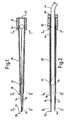
- Figure 1 is a longitudinal section through a thoracic drain introducer shown in the closed condition,
- Figure 2 is a longitudinal section of the thoracic drain introducer shown in Figure 1 in an open condition,
- Figure 3 is a cross-section on the line A-A in Figure 1,
- Figure 4 is a cross-section on the line B-B in Figure 1,
- Figure 5 is a cross-section on the line C-C in Figure 1,
- Figure 6 is a cross-section on the line A-A in Figure 2,
- Figure 7 is a cross-section on the line B-B in Figure 2,
- Figure 8 is a cross-section on the line C-C in Figure 2,
- Figure 9 is a longitudinal section through a trocar blade forming part of the appliance shown in Figure 1 but in the open condition,
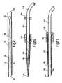
- Figure 10 is a longitudinal section through an alternative form of thoracic drain introducer shown in a closed condition.
- Figure 11 is a longitudinal section through the thoracic drain introducer shown in Figure 10, in the open condition,
- Figure 12 is a longitudinal section through a radiological intervention introducer shown in the closed condition, and
- Figure 13 is a longitudinal section through the radiological intervention introducer of Figure 12, shown in the open condition.
- Referring to the thoracic drain introducer which is illustrated in Figures 1 to 9, basically this comprises a
trocar 10 and anexpander 12. Thetrocar 10 is generally tubular, and in fact is made from a stainless steel or plastics tube. As is clear from Figures 1, 2 and 9, the trocar is of appreciable length, and the bore of the tube is larger in diameter, than the outside diameter of the thoracic drain tube which is to be used with it. For instance, if the introducer is to be used with a size 28F standard catheter, of 9.3 millimetres outside diameter, the bore of the tube from which the trocar is made, may be 12.4 millimetres. The overall length of the trocar may be in the order of 240 millimetres. - As is apparent from Figure 9, the tube from which the trocar is made, is divided into two
components openings 18. Each of theopenings 18 extends through most of the length of the tube from thedistal end 20, but near to the proximal end 22, each opening 18 terminates in a stress-relievingcircular hole 24 and beyond that, the tube is not cut away. It is to be noted that each opening 18 also tapers inwardly from the distal to the proximal end of the tube, so that where it joins thehole 24, it is quite narrow, whereas at thedistal end 20, it is relatively wide. There is also a small step in the width of theopening 18, about a third of the distance from thedistal end 20 to thehole 24. The shape of theopening 18 results in the formation of the twotrocar components hole 24, they together subtend almost the entire 360° around the longitudinal axis. However, eachcomponent - The proximal end of the trocar tube is bonded into a short
cylindrical plastics holder 30, which provides a high degree of rigidity to that end of the tube, leaving the major part of the length of the trocar tube extending cantilever fashion from the body. Further, thebody 30 provides a hand grip for the appliance. Along rubber sleeve 28 is fitted around the major part of the length of the trocar tube, and the proximal end of this sleeve is received in a counter bore 32 in thebody 30. As illustrated in Figures 1 and 2, thesleeve 28 extends forwardly of thestep 26 in theopenings 18, but terminates an appreciable distance short of thedistal end 20 of the appliance. Thesleeve 28 is, in the free condition, of considerably smaller diameter than the outside diameter of the tube from which the trocar is made, so that the sleeve exercises an inward constraining force on thetrocar components components step 26 in theopenings 18 are pressed into engagement with each other, as clearly shown in Figures 1 and 3. Thus the rubber sleeve provides a radial inward constraining force on thecomponents sleeve 28 adopts an elliptical form as illustrated in Figure 4. Adjacent to thebody 30, thesleeve 28 is fully distended, to accommodate the larger ends of thecomponents - This produces the closed condition of the appliance, illustrated in Figure 1 wherein the distal end parts of the
components components distal end 20 is forced through the skin. The cutting edges together extend across the full width of thecomponents - In the closed condition, the trocar tapers throughout its effective length between the
body 30 and thedistal end 20, so that its cross-sectional area is diminishing throughout the length between thebody 30 and thepointed end 20. The diminution of the vertical cross-section as shown in Figure 1, is greater than the dimunition in the horizontal cross-section, but there is no cross-sectional dimension of the trocar which increases to any significant extent from the proximal to the distal end in the closed condition. This assists in the insertion of the trocar through an incision made in the skin of a patient by the cutting edges, because as the tapering trocar is passed through the incision, the incision is gradually distended by the increasing cross-sectional area of the trocar. - The
expander 12 essentially comprises a thin metal orplastics tube 36 somewhat shorter than the trocar, and bonded at one end into the bore of a ring 38 (see Figure 2). The bore of theexpander tube 38 is just large enough to allow athoracic drain tube 40 of the size with which the appliance is intended to be used, to slide easily therethrough. Theexpander tube 36 has to remain substantially rigid, but given that requirement, it is otherwise made as thin walled as possible. In a typical example, where theexpander tube 36 is adapted to permit a 9.3 millimetres diameter drain tube to slide through it, the outside diameter of the expander may be 11 millimetres (i.e. the wall thickness is about 0.75 millimetres). - In use, the distal end of the
expander tube 36 is introduced into the proximal end of the trocar, passing through an inlet hole 42 in thebody 30, and then through the bore of the trocar tube. Once the forward end of the expander tube reaches the position at which thetrocar components expander tube 36 causes thetrocar components rubber sleeve 28. Eventually, the fully opened condition is arrived at as illustrated in Figure 2. Since the trocar components taper evenly towards each other from the proximal to the distal end, an appreciable longitudinal motion of theexpander tube 12 is required in order to open the trocar fully. This is advantageous, because it ensures that a steady force is required to be applied to the expander tube, in opening the trocar components. In practice, a movement of about 5 centimetres is required to carry out the opening motion where the trocar tube is about 240 millimetres long. - In the fully opened condition, the
ring 38 engages with the rear end of thebody 30, thus limiting the motion of the expander tube into the trocar, and thecomponents distal end 20. The existence of the taper can be noted by reference to the narrowannular gap 44 between the inside of the trocar components and the outside of the expander sleeve at the proximal end of the trocar. The condition of thetrocar components gap 44 at the proximal end of the trocar. - The manner in which the thoracic drain introducer shown in Figures 1 to 9 is used to carry out a drain tube introduction, will now be described to assist in understanding the invention. Before using the appliance on a patient, the
thoracic drain tube 40 is introduced through the proximal end of theexpander 12. The forward end of thetube 40 is cut off obliquely as illustrated in Figure 2. Prior to insertion of the drain, the site of insertion is cleaned under sterile conditions and local anaesthetic is injected into the intercostal space. Theexpander 12 with the drain tube (which is plugged at the other end) fitted into it, is pushed into the trocar as just described. Then thedistal end 20 of the trocar, still in the closed condition illustrated in Figure 1, is inserted through the skin and intercostal muscles into the thoracic cavity. The sharpened end of the trocar and the cutting edges form an incision through the skin to facilitate entry of the remainder of the trocar. However, entry of the trocar is also facilitated, because the thickness of the distal end is quite small in comparison to currently available trocars as used for thoracic drain insertion. Moreover, the gradual taper of thetrocar components - The trocar is prevented from being inserted beyond the desirable length by engagement of the end of the
rubber sleeve 28 with the skin. The person carrying out the operation will hold the trocar by thebody 30, and push the expander tube, by pressing on thering 38, through the trocar. As the rigid expander tube passes forwardly through thetrocar components ring 38 abuts against thebody 30. - It is a significant advantage that the insertion and expansion can be achieved with little or no tearing of the skin. To take a specific example; if the cutting edges make an incision approximately 1 centimetre wide, the periphery of the incision is 2 centimetres. The hole formed by expansion of the trocar may then have a periphery of about 3 centimetres, i.e. there is a 50% distending of the skin around the hole, and this may well be achieved without tearing.
- The
drain tube 40 can then be slid easily through theexpander 12, and through the opened forward portions of thecomponents - Finally, the
trocar 10 is withdrawn, by gripping thebody 30, and pulling it outwardly. Because thebody 30 engages with thering 38, both thetrocar 10 and theexpander 12 move together in this extraction direction, and slide over thethoracic drain tube 40. Since theforward portions drain tube 40, gripping it firmly. On the expansion of the trocar, the peripheral length of the opening in the skin may have been overstretched relatively to the outside diameter of the drain tube by say 25%, but this amount of overstretch is acceptable and will be taken up by contraction of the opening on withdrawal of the appliance. After the trocar has been completely removed from thedrain tube 40, the exposed part of the drain may then be further secured to the chest wall with adhesive tape, or other known means, and the drain connected to the underwater arm of an underwater seal drain. - In the foregoing description, the function of the
rubber sleeve 28 has been described as (i) providing the preloading force constraining thecomponents sleeve 28 has another function in that it covers theopenings 18 in the part of the trocar which does not enter the patient. This prevents the ingress of air through those openings and then through the tube passage through the trocar when the latter is being inserted. The sealing against ingress of air is essential in some instances and is further ensured by the distal end of thesleeve 28 pressing against the skin around the hole formed by the trocar during insertion and withdrawal of the applicance. - However, in addition to the use of a resilient sleeve, the
components expander 12, but the constraining force is provided by thecomponents rubber sleeve 28 is still required to seal against air ingress. Also, it is possible to use a combination of presetting the components into or towards the closed condition and a constraining sleeve. - It is also possible to flatten the distal extremities of the
components - Turning now to Figures 10 and 11, there is illustrated a thoracic drain introducer, which in principle is similar to that described with reference to Figures 1 to 9, the main difference being that the trocar is much shorter, since for some operations, it is preferred that the trocar should be as short as possible.
- Again, the applicance has a
tubular trocar 110, and a rigidtubular expander 112. Thetubular trocar 110 is divided by diametricallyopposed openings 118 into twotrocar components distal end 120. Moreover, the proximal end of the trocar tube is received in abody 130 and the rigidtubular expander 112 is received in aring 138. Athoracic drain tube 140 is also illustrated. - It is unnecessary to described the appliance illustrated in Figures 10 and 11 in greater detail, because it will be apparent, that the construction and function is very similar to that of the appliance illustrated in Figures 1 to 9.
- In Figures 12 and 13 there is illustrated a radiological intervention introducer, which again is quite similar in construction and use to the appliance shown in Figures 1 to 9, although in this instance, the bore of the expander can be smaller, because it is only intended to introduce appliances such as wires and cables rather than drain tubes through the skin of the patient.
- Again, there is a
tubular trocar 210 and a rigidtubular expander 212. Thetubular trocar 210 tapers rather more sharply than thetrocar 10 illustrated in Figure 1, but it has diametrically opposedopenings 218 dividing it intotrocar components distal end 220, which is sharpened and formed with cutting edges, to ahole 224 formed at the end of eachopening 218 near to the proximal end of the trocar tube. Moreover, as in previous constructions, the trocar tube is received in abody 230 which also provides a hand grip. It will be noted that thestep 226 in theopening 218 is about half way along the length of the trocar tube from thedistal end 220 to thebody 230, that is the forwardly extending parts of thecomponents - There is also a
rubber sleeve 228 surrounding the trocar components on the proximal side of thestep 226, and performing the functions of thesleeve 28 previously described. - The
tubular expander 212 extends from aring 238, and can be pushed into the trocar through thebody 230, for the purpose of expanding thecomponents sleeve 228. It will be noted from Figure 13 however, that in the fully open condition, where thering 238 abuts against thebody 230, the distal end of theexpander tube 212 is well forward of the forward termination of thesleeve 228. Indeed, the expander tube can be made long enough to extend to the distal end of the trocar to support thecomponents - The radiological intervention introducer illustrated in Figures 12 and 13 is used in a similar manner to that described with reference to Figures 1 to 9, excepting that after the
expander 212 has been fully inserted, in order to open up the incision formed through the skin of the patient, then instead of passing a drain tube through the bore of the expander, an operating tool, a wire, optical fibre or the like is passed through that bore into the required location within the patient. - In some instance, a guide wire will already have been passed through the skin of the patient into a desired location in an organ on which an operation is to be performed. The appliance illustrated in Figures 12 and 13 is then threaded over this guide wire and can be used as previously described, excepting that the location of the opening formed by the trocar is determined by the guide wire and the trocar, and any tube passed through the trocar, follows the guide wire to the organ on which the operation is being performed.
- For some operations, it will be possible to leave the introducerin-situ, until the operation has been completed. For other operations however, the introducer is withdrawn by pulling it away from the patient, thus extracting the
trocar components - The extreme simplicity of construction of the device in accordance with the invention, means that it can be produced relatively cheaply. Consequently, after a single use, the appliance can be discarded, rendering it a disposable item. It will be appreciated, that this eliminates the necessity for resterilisation of the appliance, and also ensures that there cannot be any cross-infection arising out of use of the appliance.
- It will also be appreciated, that the construction may be varied from that which is illustrated in the drawings, without departing from the scope of the invention. It will further be appreciated that any of the features described with reference to any one of the three preferred embodiments described above could be employed on either of the other two embodiments.
Claims (9)
- A surgical appliance for forming an opening through the skin of a patient or animal comprising a trocar (10, 110, 210) having a distal end (20, 120 200) which is intended to penetrate the skin and a generally parallel-sided tube divided through part only of its length from the distal end by two cut-away parts (18, 118, 218) of the wall of the tube into two component parts or portions (14, 16; 114, 116; 214 216) which, by virtue of the cut-away openings are adapted to move relatively to each other between a closed condition and an open condition, the two component parts or portions being preloaded into the closed condition, in which they converge towards the distal end as permitted by the openings in the wall of the tube, and an expander (12, 112, 212) which can be inserted into the trocar from the proximal end towards the distal end, and which, when so inserted, causes the trocar to expand, from the closed to the open condition,characterised in that a distendable sleeve (28, 228) is fitted around the two trocar component parts or portions (14, 16; 114, 116; 214, 216) the bore of the sleeve in its free condition being a close fit on the outside diameter of the tube and the length and location of the sleeve being such that it extends from the non-divided part of the tube over a significant length of the divided part of the tube, so that the sleeve performs the two functions of: providing by its distal end a stop to limit penetration of the trocar through the skin and preventing ingress of air through the openings formed between the component parts or portions when the latter are moved into the open condition.
- A surgical appliance as claimed in Claim 1,characterised in that the sleeve (28,228) in its free condition is of smaller bore than the outside diameter of the tube so that it applies an inward compressive force to the components or portions of the tube.
- A surgical appliance as claimed in Claim 1 or Claim 2,characterised in that the trocar component parts or portions (14,16; 114,116; 214,216) are deformed inwardly (i.e. towards each other) beyond the elastic limit of the material from which the tube is made, so that the component parts or portions adopt a "set" in the closed condition and part of the preloading is then provided by that permanent "set".
- A surgical appliance as claimed in any one of Claims 1 to 3,characterised in that the design of the trocar tube (10,110,210) is such that when it is in the open condition,there is no substantial increase in the cross-section of the trocar towards the distal end.
- A surgical appliance as claimed in any one of Claims 1 to 4,characterised in that the distal end (20,120,220) of the trocar is formed with one or more cutting edges adapted to make an incision in the skin as that end of the trocar is forced through the skin,the cutting edge extending across substantially the full width of the distal end of the trocar in the closed condition.
- A surgical appliance as claimed in any one of Claims 1 to 5,characterised in that the expander (12,112,212) comprises a rigid tube, the outside diameter of which is equal to the spacing between the trocar component parts or portions (14,16;114,116;214,216) when in the open condition, so that when the expander is inserted through the proximal end of the trocar,it engages with the insides of the trocar component parts or portions and forces them apart.
- A surgical appliance as claimed in any one of Claims 1 to 6,characterised in that the arrangement of the trocar component parts or portions is such that a longitudinal movement of at least two centimetres of the expander is required to move the component parts or portions from the closed condition to the open condition.
- A surgical appliance as claimed in any one of Claims 1 to 7,characterised in that the trocar components are parts of a single element, partially divided from each other by a slit or slits (18,118,218).
- A surgical appliance as claimed in any one of Claims 1 to 8,characterised in that each trocar component (14,16; 114,116; 214,216) has a blade-like configuration, the blades being bowed outwardly as seen in lateral cross-section, so that in their closed condition, the components contact each other along the longitudinal edges, and in the open condition, they approximate in cross-section to parts of an annulus.
Applications Claiming Priority (2)
| Application Number | Priority Date | Filing Date | Title |
|---|---|---|---|
| GB848424436AGB8424436D0 (en) | 1984-09-27 | 1984-09-27 | Surgical appliance |
| GB8424436 | 1984-09-27 |
Publications (3)
| Publication Number | Publication Date |
|---|---|
| EP0177177A2 EP0177177A2 (en) | 1986-04-09 |
| EP0177177A3 EP0177177A3 (en) | 1987-04-22 |
| EP0177177B1true EP0177177B1 (en) | 1991-07-03 |
Family
ID=10567357
Family Applications (1)
| Application Number | Title | Priority Date | Filing Date |
|---|---|---|---|
| EP85306189AExpiredEP0177177B1 (en) | 1984-09-27 | 1985-09-02 | A surgical appliance for forming an opening through the skin |
Country Status (5)
| Country | Link |
|---|---|
| US (1) | US4716901A (en) |
| EP (1) | EP0177177B1 (en) |
| JP (1) | JPS6185934A (en) |
| DE (1) | DE3583368D1 (en) |
| GB (1) | GB8424436D0 (en) |
Cited By (17)
| Publication number | Priority date | Publication date | Assignee | Title |
|---|---|---|---|---|
| US7449011B2 (en) | 2001-08-01 | 2008-11-11 | Tyco Healthcare Group Lp | Apparatus and method for providing percutaneous access and medicament to a target surgical site |
| US7479150B2 (en) | 2003-09-19 | 2009-01-20 | Tyco Healthcare Group Lp | Trocar insertion apparatus |
| US7713193B2 (en) | 2003-12-05 | 2010-05-11 | Onset Medical Corporation | Expandable percutaneous sheath |
| US7892203B2 (en) | 2004-09-09 | 2011-02-22 | Onset Medical Corporation | Expandable transluminal sheath |
| US7896897B2 (en) | 2002-11-22 | 2011-03-01 | Tyco Healthcare Group Lp | Sheath introduction apparatus and method |
| US8092481B2 (en) | 2005-06-03 | 2012-01-10 | Onset Medical Corporation | Expandable percutaneous sheath |
| US8540628B2 (en) | 2010-02-12 | 2013-09-24 | Covidien Lp | Expandable thoracic access port |
| US8574155B2 (en) | 2010-02-12 | 2013-11-05 | Covidien Lp | Expandable surgical access port |
| US8579810B2 (en) | 2010-02-12 | 2013-11-12 | Covidien Lp | Expandable thoracic access port |
| US8597277B2 (en) | 2004-09-09 | 2013-12-03 | Onset Medical Corporation | Expandable transluminal sheath |
| US8597180B2 (en) | 2010-08-12 | 2013-12-03 | Covidien Lp | Expandable thoracic access port |
| US8777849B2 (en) | 2010-02-12 | 2014-07-15 | Covidien Lp | Expandable thoracic access port |
| US8795326B2 (en) | 2007-10-05 | 2014-08-05 | Covidien Lp | Expanding seal anchor for single incision surgery |
| US8864658B2 (en) | 2010-08-12 | 2014-10-21 | Covidien Lp | Expandable surgical access port |
| US8961408B2 (en) | 2010-08-12 | 2015-02-24 | Covidien Lp | Expandable surgical access port |
| US9241735B2 (en) | 2003-12-05 | 2016-01-26 | Onset Medical Corporation | Expandable percutaneous sheath |
| US9247955B2 (en) | 2010-08-12 | 2016-02-02 | Covidien Lp | Thoracic access port |
Families Citing this family (249)
| Publication number | Priority date | Publication date | Assignee | Title |
|---|---|---|---|---|
| US5090408A (en)* | 1985-10-18 | 1992-02-25 | Bryan T. Spofford | Transtracheal catheter system and method |
| US5186168A (en)* | 1984-11-21 | 1993-02-16 | Spofford Bryan T | Transtracheal catheter system and method |
| US4877021A (en)* | 1985-05-14 | 1989-10-31 | Gary Higer | Emergency airway surgical device |
| GB8513702D0 (en)* | 1985-05-30 | 1985-07-03 | Gill S S | Expansible trocar |
| US6770074B2 (en)* | 1988-06-13 | 2004-08-03 | Gary Karlin Michelson | Apparatus for use in inserting spinal implants |
| EP0703757B1 (en) | 1988-06-13 | 2003-08-27 | Karlin Technology, Inc. | Apparatus for inserting spinal implants |
| US6277136B1 (en) | 1990-03-02 | 2001-08-21 | General Surgical Innovations, Inc. | Method for developing an anatomic space |
| US5514153A (en)* | 1990-03-02 | 1996-05-07 | General Surgical Innovations, Inc. | Method of dissecting tissue layers |
| US5295994A (en)* | 1991-11-15 | 1994-03-22 | Bonutti Peter M | Active cannulas |
| US5201756A (en)* | 1990-06-20 | 1993-04-13 | Danforth Biomedical, Inc. | Radially-expandable tubular elements for use in the construction of medical devices |
| US5389080A (en)* | 1990-07-26 | 1995-02-14 | Yoon; Inbae | Endoscopic portal for use in endoscopic procedures and methods therefor |
| US5199427A (en)* | 1990-10-19 | 1993-04-06 | Ballard Medical Products | Multi-layered transtracheal caatheter |
| US5218957A (en)* | 1990-10-19 | 1993-06-15 | Ballard Medical Products | Multi-layered transtracheal catheter |
| US5230332A (en)* | 1990-10-22 | 1993-07-27 | Ballard Medical Products | Methods and apparatus for a micro-tracheal catheter hub assembly |
| US5165420A (en)* | 1990-12-21 | 1992-11-24 | Ballard Medical Products | Bronchoalveolar lavage catheter |
| US5158569A (en)* | 1990-12-21 | 1992-10-27 | Ballard Medical Products | Catheter placement locking and sealing device |
| US5246012A (en)* | 1990-12-21 | 1993-09-21 | Ballard Medical Products | Bronchoalveolar lavage catheter |
| US5176659A (en)* | 1991-02-28 | 1993-01-05 | Mario Mancini | Expandable intravenous catheter and method of using |
| US5242409A (en)* | 1991-05-16 | 1993-09-07 | Applied Medical Resources Corporation | Flexible access device |
| US5183464A (en)* | 1991-05-17 | 1993-02-02 | Interventional Thermodynamics, Inc. | Radially expandable dilator |
| US5123905A (en)* | 1991-06-07 | 1992-06-23 | Kelman Charles D | Intraocular lens injector |
| US5339809A (en)* | 1991-12-04 | 1994-08-23 | Beck Jr Charles A | Method of inserting a cricothyroidal endotracheal device between the cricoid and thyroid cartilages for treatment of chronic respiratory disorders |
| US5230705A (en)* | 1992-03-13 | 1993-07-27 | Wilk Peter J | Method of intravenous catheterization device |
| US5246424A (en)* | 1992-03-13 | 1993-09-21 | Wilk Peter J | Device and method for use in obtaining access to an internal body organ |
| GR930100244A (en)* | 1992-06-30 | 1994-02-28 | Ethicon Inc | Flexible endoscopic surgical port |
| US5383886A (en)* | 1992-10-13 | 1995-01-24 | Kensey Nash Corporation | Methods and instruments for performing medical procedures percutaneously without a trocar |
| US5246425A (en)* | 1992-09-21 | 1993-09-21 | Daniel Hunsberger | Trocar and cannula assembly |
| US5580344A (en)* | 1992-10-22 | 1996-12-03 | Hasson; Harrith M. | Incision converter & method of using the same |
| US5814073A (en)* | 1996-12-13 | 1998-09-29 | Bonutti; Peter M. | Method and apparatus for positioning a suture anchor |
| US6338730B1 (en) | 1993-02-04 | 2002-01-15 | Peter M. Bonutti | Method of using expandable cannula |
| US5961499A (en)* | 1993-02-04 | 1999-10-05 | Peter M. Bonutti | Expandable cannula |
| US5674240A (en)* | 1993-02-04 | 1997-10-07 | Peter M. Bonutti | Expandable cannula |
| US5320611A (en)* | 1993-02-04 | 1994-06-14 | Peter M. Bonutti | Expandable cannula having longitudinal wire and method of use |
| US5814058A (en)* | 1993-03-05 | 1998-09-29 | Innerdyne, Inc. | Method and apparatus employing conformable sleeve for providing percutaneous access |
| US5431676A (en) | 1993-03-05 | 1995-07-11 | Innerdyne Medical, Inc. | Trocar system having expandable port |
| ES2126675T3 (en)* | 1993-05-28 | 1999-04-01 | Viktor Krutten | SURGICAL INSTRUMENT FOR APPLICATION FOR CATHETERS OR SIMILAR. |
| JPH07477A (en)* | 1993-06-11 | 1995-01-06 | Katsuya Takasu | Ear meridian point sticking needle and pierce |
| US5304119A (en)* | 1993-06-24 | 1994-04-19 | Monsanto Company | Instrument for injecting implants through animal hide |
| JP3759178B2 (en)* | 1994-07-11 | 2006-03-22 | テルモ株式会社 | Trocar tube and trocar provided with the same |
| US5460170A (en)* | 1994-08-23 | 1995-10-24 | Hammerslag; Julius G. | Adjustable surgical retractor |
| US5570700A (en)* | 1994-10-03 | 1996-11-05 | Vogeler; Douglas M. | Elliptical biopsy punch |
| FR2726691B1 (en)* | 1994-11-08 | 1997-01-24 | Thomson Csf | LARGE-DIMENSIONAL PHOTODETECTOR AND METHOD FOR PRODUCING SUCH A PHOTODETECTOR |
| US5624459A (en)* | 1995-01-26 | 1997-04-29 | Symbiosis Corporation | Trocar having an improved cutting tip configuration |
| WO1996025889A1 (en)* | 1995-02-22 | 1996-08-29 | Jacques Michael Casparian | Dilator/hair implanter device |
| US5707359A (en)* | 1995-11-14 | 1998-01-13 | Bufalini; Bruno | Expanding trocar assembly |
| US5776110A (en)* | 1996-01-26 | 1998-07-07 | United States Surgical Corporation | Thoracic port |
| US5817062A (en)* | 1996-03-12 | 1998-10-06 | Heartport, Inc. | Trocar |
| US5792044A (en) | 1996-03-22 | 1998-08-11 | Danek Medical, Inc. | Devices and methods for percutaneous surgery |
| US20040176763A1 (en)* | 1996-03-22 | 2004-09-09 | Foley Kevin T. | Methods for percutaneous surgery |
| US5782916A (en)* | 1996-08-13 | 1998-07-21 | Galt Laboratories, Inc. | Device for maintaining urinary continence |
| US5718717A (en)* | 1996-08-19 | 1998-02-17 | Bonutti; Peter M. | Suture anchor |
| AU4029197A (en)* | 1996-09-06 | 1998-03-26 | Gore Enterprise Holdings, Inc. | Medical evacuation and irrigation system |
| US5902282A (en)* | 1996-12-26 | 1999-05-11 | Johnson & Johnson Medical, Inc. | Step-down catheter |
| WO1998029026A2 (en)* | 1996-12-30 | 1998-07-09 | Imagyn Medical Technologies, Inc. | Expandable access device and method of constructing and using same |
| GB9707997D0 (en) | 1997-04-21 | 1997-06-11 | Walker Justin R A | Surgical implement |
| US6175758B1 (en) | 1997-07-15 | 2001-01-16 | Parviz Kambin | Method for percutaneous arthroscopic disc removal, bone biopsy and fixation of the vertebrae |
| US6030364A (en)* | 1997-10-03 | 2000-02-29 | Boston Scientific Corporation | Apparatus and method for percutaneous placement of gastro-intestinal tubes |
| AU9326498A (en) | 1997-11-24 | 1999-06-10 | Johnson & Johnson Research Pty. Limited | Biopsy instrument with continuous tissue receiving chamber |
| US5985803A (en) | 1997-12-05 | 1999-11-16 | The Lubrizol Corporation | Polyethoxylated alcohol-based phosphonates for metal working lubricants |
| US6045551A (en) | 1998-02-06 | 2000-04-04 | Bonutti; Peter M. | Bone suture |
| US5899854A (en)* | 1998-04-20 | 1999-05-04 | University Of New Mexico | Speculum and method for inserting an elongated instrument into an animal's body |
| US6464999B1 (en) | 1998-06-17 | 2002-10-15 | Galt Incorporated | Bioadhesive medical devices |
| US6245052B1 (en) | 1998-07-08 | 2001-06-12 | Innerdyne, Inc. | Methods, systems, and kits for implanting articles |
| US6187000B1 (en)* | 1998-08-20 | 2001-02-13 | Endius Incorporated | Cannula for receiving surgical instruments |
| US7799036B2 (en) | 1998-08-20 | 2010-09-21 | Zimmer Spine, Inc. | Method and apparatus for securing vertebrae |
| US7641670B2 (en)* | 1998-08-20 | 2010-01-05 | Zimmer Spine, Inc. | Cannula for receiving surgical instruments |
| EP1194074A4 (en)* | 1999-05-19 | 2002-09-11 | Innerdyne Medical Inc | SYSTEM AND METHOD TO ENABLE VASCULAR ACCESS |
| US6692462B2 (en)* | 1999-05-19 | 2004-02-17 | Mackenzie Andrew J. | System and method for establishing vascular access |
| US6368343B1 (en) | 2000-03-13 | 2002-04-09 | Peter M. Bonutti | Method of using ultrasonic vibration to secure body tissue |
| US6447516B1 (en) | 1999-08-09 | 2002-09-10 | Peter M. Bonutti | Method of securing tissue |
| US6635073B2 (en) | 2000-05-03 | 2003-10-21 | Peter M. Bonutti | Method of securing body tissue |
| US9138222B2 (en) | 2000-03-13 | 2015-09-22 | P Tech, Llc | Method and device for securing body tissue |
| US7094251B2 (en) | 2002-08-27 | 2006-08-22 | Marctec, Llc. | Apparatus and method for securing a suture |
| US10327880B2 (en) | 2000-04-14 | 2019-06-25 | Attenuex Technologies, Inc. | Attenuation device for use in an anatomical structure |
| US6585746B2 (en) | 2000-04-20 | 2003-07-01 | Philip L. Gildenberg | Hair transplantation method and apparatus |
| US7056321B2 (en)* | 2000-08-01 | 2006-06-06 | Endius, Incorporated | Method of securing vertebrae |
| US7985247B2 (en)* | 2000-08-01 | 2011-07-26 | Zimmer Spine, Inc. | Methods and apparatuses for treating the spine through an access device |
| US7204851B2 (en)* | 2000-08-30 | 2007-04-17 | Sdgi Holdings, Inc. | Method and apparatus for delivering an intervertebral disc implant |
| US6986772B2 (en)* | 2001-03-01 | 2006-01-17 | Michelson Gary K | Dynamic lordotic guard with movable extensions for creating an implantation space posteriorly in the lumbar spine |
| AU2002247230B9 (en) | 2001-03-01 | 2007-05-10 | Warsaw Orthopedic, Inc. | Dynamic lordotic guard with movable extensions for creating an implantation space posteriorly in the lumbar spine and method for use thereof |
| US6896680B2 (en)* | 2001-03-01 | 2005-05-24 | Gary K. Michelson | Arcuate dynamic lordotic guard with movable extensions for creating an implantation space posteriorly in the lumbar spine |
| DE60230247D1 (en)* | 2001-04-16 | 2009-01-22 | Cytyc Corp | RADIAL EXPANDABLE DILATOR |
| US7144393B2 (en)* | 2001-05-15 | 2006-12-05 | Dipoto Gene P | Structure for receiving surgical instruments |
| US6719765B2 (en) | 2001-12-03 | 2004-04-13 | Bonutti 2003 Trust-A | Magnetic suturing system and method |
| US7029482B1 (en)* | 2002-01-22 | 2006-04-18 | Cardica, Inc. | Integrated anastomosis system |
| US9155544B2 (en) | 2002-03-20 | 2015-10-13 | P Tech, Llc | Robotic systems and methods |
| US7261688B2 (en) | 2002-04-05 | 2007-08-28 | Warsaw Orthopedic, Inc. | Devices and methods for percutaneous tissue retraction and surgery |
| US8142365B2 (en)* | 2002-05-31 | 2012-03-27 | Vidacare Corporation | Apparatus and method for accessing the bone marrow of the sternum |
| US11298202B2 (en) | 2002-05-31 | 2022-04-12 | Teleflex Life Sciences Limited | Biopsy devices and related methods |
| US9451968B2 (en)* | 2002-05-31 | 2016-09-27 | Vidacare LLC | Powered drivers, intraosseous devices and methods to access bone marrow |
| US11337728B2 (en) | 2002-05-31 | 2022-05-24 | Teleflex Life Sciences Limited | Powered drivers, intraosseous devices and methods to access bone marrow |
| US7811260B2 (en) | 2002-05-31 | 2010-10-12 | Vidacare Corporation | Apparatus and method to inject fluids into bone marrow and other target sites |
| US7850620B2 (en)* | 2002-05-31 | 2010-12-14 | Vidacare Corporation | Biopsy devices and related methods |
| EP2039298B1 (en) | 2002-05-31 | 2017-10-25 | Vidacare LLC | Apparatus to access bone marrow |
| US10973545B2 (en) | 2002-05-31 | 2021-04-13 | Teleflex Life Sciences Limited | Powered drivers, intraosseous devices and methods to access bone marrow |
| US7951089B2 (en)* | 2002-05-31 | 2011-05-31 | Vidacare Corporation | Apparatus and methods to harvest bone and bone marrow |
| US9314228B2 (en)* | 2002-05-31 | 2016-04-19 | Vidacare LLC | Apparatus and method for accessing the bone marrow |
| US9072543B2 (en) | 2002-05-31 | 2015-07-07 | Vidacare LLC | Vascular access kits and methods |
| US8668698B2 (en) | 2002-05-31 | 2014-03-11 | Vidacare Corporation | Assembly for coupling powered driver with intraosseous device |
| US8641715B2 (en) | 2002-05-31 | 2014-02-04 | Vidacare Corporation | Manual intraosseous device |
| US8690791B2 (en) | 2002-05-31 | 2014-04-08 | Vidacare Corporation | Apparatus and method to access the bone marrow |
| US20070049945A1 (en) | 2002-05-31 | 2007-03-01 | Miller Larry J | Apparatus and methods to install, support and/or monitor performance of intraosseous devices |
| US10973532B2 (en) | 2002-05-31 | 2021-04-13 | Teleflex Life Sciences Limited | Powered drivers, intraosseous devices and methods to access bone marrow |
| US7004947B2 (en)* | 2002-06-24 | 2006-02-28 | Endius Incorporated | Surgical instrument for moving vertebrae |
| US7473222B2 (en)* | 2002-06-26 | 2009-01-06 | Warsaw Orthopedic, Inc. | Instruments and methods for minimally invasive tissue retraction and surgery |
| US6945933B2 (en)* | 2002-06-26 | 2005-09-20 | Sdgi Holdings, Inc. | Instruments and methods for minimally invasive tissue retraction and surgery |
| US7329268B2 (en) | 2002-07-02 | 2008-02-12 | Warsaw Orthopedic, Inc. | Expandable percutaneous sheath |
| US7309334B2 (en) | 2002-07-23 | 2007-12-18 | Von Hoffmann Gerard | Intracranial aspiration catheter |
| US8425549B2 (en) | 2002-07-23 | 2013-04-23 | Reverse Medical Corporation | Systems and methods for removing obstructive matter from body lumens and treating vascular defects |
| US6648888B1 (en) | 2002-09-06 | 2003-11-18 | Endius Incorporated | Surgical instrument for moving a vertebra |
| WO2004039235A2 (en)* | 2002-10-25 | 2004-05-13 | Endius Incorporated | Apparatus and methods for shielding body structures during surgery |
| ES2570595T3 (en)* | 2002-10-31 | 2016-05-19 | Smiths Group Plc | Dilator |
| AU2003295934B2 (en) | 2002-11-23 | 2009-02-26 | Frey, George A. | Distraction and retraction system for spinal surgery |
| US6915804B2 (en)* | 2002-12-03 | 2005-07-12 | University Of Florida | Tracheotomy surgical device |
| EP1599143B1 (en)* | 2003-01-31 | 2014-01-29 | Simpson, Philip J. | System for rapid placement of chest tubes |
| US7811293B2 (en)* | 2003-01-31 | 2010-10-12 | Philip J. Simpson | System and method for rapid placement of chest tubes |
| US7497864B2 (en) | 2003-04-30 | 2009-03-03 | Marctec, Llc. | Tissue fastener and methods for using same |
| US20050143690A1 (en)* | 2003-05-01 | 2005-06-30 | High Kenneth A. | Cystotomy catheter capture device and methods of using same |
| US7645232B2 (en)* | 2003-05-16 | 2010-01-12 | Zimmer Spine, Inc. | Access device for minimally invasive surgery |
| US9504477B2 (en) | 2003-05-30 | 2016-11-29 | Vidacare LLC | Powered driver |
| DE602004018342D1 (en)* | 2003-08-26 | 2009-01-22 | Zimmer Spine Inc | ACCESS SYSTEMS FOR MINIMALLY INVASIVE SURGERY |
| US7226451B2 (en)* | 2003-08-26 | 2007-06-05 | Shluzas Alan E | Minimally invasive access device and method |
| US20050090822A1 (en)* | 2003-10-24 | 2005-04-28 | Dipoto Gene | Methods and apparatus for stabilizing the spine through an access device |
| US7655012B2 (en)* | 2003-10-02 | 2010-02-02 | Zimmer Spine, Inc. | Methods and apparatuses for minimally invasive replacement of intervertebral discs |
| US20050090899A1 (en)* | 2003-10-24 | 2005-04-28 | Dipoto Gene | Methods and apparatuses for treating the spine through an access device |
| US7731737B2 (en)* | 2003-10-24 | 2010-06-08 | Zimmer Spine, Inc. | Methods and apparatuses for fixation of the spine through an access device |
| CN101536926B (en) | 2004-01-26 | 2012-07-18 | 维达保健公司 | Manual interosseous device |
| US7815642B2 (en)* | 2004-01-26 | 2010-10-19 | Vidacare Corporation | Impact-driven intraosseous needle |
| US7344495B2 (en)* | 2004-01-27 | 2008-03-18 | Arvik Enterprises, Llc | Surgical retractor apparatus for use with a surgical port |
| US7195592B2 (en)* | 2004-01-27 | 2007-03-27 | Sundaram Ravikumar | Surgical retractor apparatus for use with a surgical port |
| WO2005072402A2 (en)* | 2004-01-29 | 2005-08-11 | Cannuflow, Inc. | Atraumatic arthroscopic instrument sheath |
| US20060041270A1 (en)* | 2004-05-07 | 2006-02-23 | Jay Lenker | Medical access sheath |
| US20060052812A1 (en)* | 2004-09-07 | 2006-03-09 | Michael Winer | Tool for preparing a surgical site for an access device |
| US20060135962A1 (en)* | 2004-09-09 | 2006-06-22 | Kick George F | Expandable trans-septal sheath |
| WO2006042241A2 (en) | 2004-10-08 | 2006-04-20 | Nuvasive, Inc. | Surgical access system and related methods |
| US9463012B2 (en) | 2004-10-26 | 2016-10-11 | P Tech, Llc | Apparatus for guiding and positioning an implant |
| US9271766B2 (en) | 2004-10-26 | 2016-03-01 | P Tech, Llc | Devices and methods for stabilizing tissue and implants |
| US9173647B2 (en) | 2004-10-26 | 2015-11-03 | P Tech, Llc | Tissue fixation system |
| US20060089646A1 (en) | 2004-10-26 | 2006-04-27 | Bonutti Peter M | Devices and methods for stabilizing tissue and implants |
| US8998848B2 (en)* | 2004-11-12 | 2015-04-07 | Vidacare LLC | Intraosseous device and methods for accessing bone marrow in the sternum and other target areas |
| US20060253102A1 (en)* | 2004-12-21 | 2006-11-09 | Nance Edward J | Non-expandable transluminal access sheath |
| US9089323B2 (en) | 2005-02-22 | 2015-07-28 | P Tech, Llc | Device and method for securing body tissue |
| US20060212062A1 (en)* | 2005-03-16 | 2006-09-21 | David Farascioni | Radially expandable access system including trocar seal |
| US20060259061A1 (en)* | 2005-04-22 | 2006-11-16 | Kick George F | Expandable sheath for percutaneous upper gastrointestinal tract access |
| WO2007038429A1 (en) | 2005-09-27 | 2007-04-05 | Endius, Inc. | Methods and apparatuses for stabilizing the spine through an access device |
| US20070078466A1 (en)* | 2005-09-30 | 2007-04-05 | Restoration Robotics, Inc. | Methods for harvesting follicular units using an automated system |
| US7962192B2 (en) | 2005-09-30 | 2011-06-14 | Restoration Robotics, Inc. | Systems and methods for aligning a tool with a desired location or object |
| US10299871B2 (en) | 2005-09-30 | 2019-05-28 | Restoration Robotics, Inc. | Automated system and method for hair removal |
| US20070156096A1 (en)* | 2005-11-10 | 2007-07-05 | Terumo Kabushiki Kaisha | Puncture device |
| US7967820B2 (en) | 2006-02-07 | 2011-06-28 | P Tech, Llc. | Methods and devices for trauma welding |
| US8496657B2 (en) | 2006-02-07 | 2013-07-30 | P Tech, Llc. | Methods for utilizing vibratory energy to weld, stake and/or remove implants |
| US11253296B2 (en) | 2006-02-07 | 2022-02-22 | P Tech, Llc | Methods and devices for intracorporeal bonding of implants with thermal energy |
| US11278331B2 (en) | 2006-02-07 | 2022-03-22 | P Tech Llc | Method and devices for intracorporeal bonding of implants with thermal energy |
| US9439642B2 (en) | 2006-02-07 | 2016-09-13 | P Tech, Llc | Methods and devices for utilizing bondable materials |
| US20070233089A1 (en)* | 2006-02-17 | 2007-10-04 | Endius, Inc. | Systems and methods for reducing adjacent level disc disease |
| US20070208366A1 (en)* | 2006-03-03 | 2007-09-06 | Richard Pellegrino | Minimally invasive tissue expander systems and methods |
| US7585547B2 (en)* | 2006-04-13 | 2009-09-08 | Solopower, Inc. | Method and apparatus to form thin layers of materials on a base |
| US11246638B2 (en) | 2006-05-03 | 2022-02-15 | P Tech, Llc | Methods and devices for utilizing bondable materials |
| JP5226197B2 (en)* | 2006-08-25 | 2013-07-03 | オリンパス株式会社 | Endoscope guide tube and endoscope apparatus |
| US8944069B2 (en) | 2006-09-12 | 2015-02-03 | Vidacare Corporation | Assemblies for coupling intraosseous (IO) devices to powered drivers |
| EP3189787B1 (en) | 2006-09-12 | 2019-01-09 | Teleflex Medical Devices S.à.r.l. | Medical procedures trays and related methods |
| EP2068743B1 (en)* | 2006-09-12 | 2017-03-15 | Vidacare LLC | Medical procedures trays, kits and related methods |
| EP2073728B1 (en)* | 2006-09-12 | 2018-11-07 | Teleflex Medical Devices S.à.r.l. | Biopsy device |
| US8974410B2 (en) | 2006-10-30 | 2015-03-10 | Vidacare LLC | Apparatus and methods to communicate fluids and/or support intraosseous devices |
| US7819842B2 (en)* | 2006-11-21 | 2010-10-26 | Medtronic, Inc. | Chronically implantable guide tube for repeated intermittent delivery of materials or fluids to targeted tissue sites |
| US8337518B2 (en) | 2006-12-20 | 2012-12-25 | Onset Medical Corporation | Expandable trans-septal sheath |
| US8652154B2 (en) | 2006-12-28 | 2014-02-18 | Orthovita, Inc. | Non-resorbable implantable guides |
| US8617185B2 (en) | 2007-02-13 | 2013-12-31 | P Tech, Llc. | Fixation device |
| US8066717B2 (en) | 2007-03-19 | 2011-11-29 | Restoration Robotics, Inc. | Device and method for harvesting and implanting follicular units |
| WO2009002677A1 (en) | 2007-06-26 | 2008-12-31 | Restoration Robotics, Inc. | Follicular unit harvesting tools including devices and their use for severing connective tissue |
| US8118826B2 (en)* | 2007-09-27 | 2012-02-21 | Swan Valley Medical, Incorporated | Method of performing a suprapubic transurethral cystostomy and associated procedures and apparatus therefor |
| US8382785B2 (en)* | 2007-09-27 | 2013-02-26 | Swan Valley Medical Incorporated | Apparatus and method for performing cystotomy procedures |
| BRPI0818608A2 (en) | 2007-10-05 | 2015-04-22 | Synthes Gmbh | Sequential directional dilatation system for dilating from a nerve of a patient's anatomy, and method for forming an access opening through a psoas muscle to a patient's spine using a dilatation system |
| US20090163942A1 (en)* | 2007-12-20 | 2009-06-25 | Cuevas Brian J | Tracheostomy punch dilator |
| US8215309B2 (en)* | 2008-02-15 | 2012-07-10 | Single Jr Gordon W | Percutaneous emergent cricothyroidotomy airway device |
| WO2009114523A1 (en)* | 2008-03-14 | 2009-09-17 | Synthes Usa, Llc | Nested expandable sleeve implant |
| US8226664B2 (en) | 2008-03-18 | 2012-07-24 | Restoration Robotics, Inc. | Biological unit removal tools with movable retention member |
| US8968192B2 (en)* | 2008-06-06 | 2015-03-03 | Warsaw Orthopedic, Inc. | Systems and methods for tissue retraction |
| US20100082042A1 (en)* | 2008-09-30 | 2010-04-01 | Drews Michael J | Biological unit removal tool with occluding member |
| US8790387B2 (en) | 2008-10-10 | 2014-07-29 | Edwards Lifesciences Corporation | Expandable sheath for introducing an endovascular delivery device into a body |
| US8690936B2 (en)* | 2008-10-10 | 2014-04-08 | Edwards Lifesciences Corporation | Expandable sheath for introducing an endovascular delivery device into a body |
| US8226554B2 (en)* | 2008-10-30 | 2012-07-24 | Warsaw Orthopedic, Inc. | Retractor assemblies for surgery in a patient |
| WO2010068467A1 (en) | 2008-11-25 | 2010-06-17 | Attenuex Technologies, Inc. | Implant with high vapor pressure medium |
| US8992558B2 (en)* | 2008-12-18 | 2015-03-31 | Osteomed, Llc | Lateral access system for the lumbar spine |
| CA2757870C (en)* | 2009-04-30 | 2016-02-02 | Cook Medical Technologies Llc | System and method for fiducial deployment |
| US9072542B2 (en)* | 2009-12-18 | 2015-07-07 | Cook Medical Technologies Llc | System and method for fiducial deployment |
| US8298246B2 (en) | 2010-04-01 | 2012-10-30 | Restoration Robotics, Inc. | Follicular unit removal tool with pivoting retention member |
| US8728162B2 (en) | 2010-04-15 | 2014-05-20 | Osteomed, Llc | Direct lateral spine system instruments, implants and associated methods |
| US8128639B2 (en) | 2010-05-20 | 2012-03-06 | Restoration Robotics, Inc. | Tools and methods for harvesting follicular units |
| US9155503B2 (en) | 2010-10-27 | 2015-10-13 | Cadwell Labs | Apparatus, system, and method for mapping the location of a nerve |
| US9241701B2 (en) | 2010-11-11 | 2016-01-26 | Depuy Mitek, Inc. | Cannula system and method for partial thickness rotator cuff repair |
| DE102010060877B4 (en) | 2010-11-29 | 2013-08-29 | Reiner Kunz | trocar |
| US9498289B2 (en) | 2010-12-21 | 2016-11-22 | Restoration Robotics, Inc. | Methods and systems for directing movement of a tool in hair transplantation procedures |
| US9119665B2 (en) | 2011-03-21 | 2015-09-01 | Covidien Lp | Thoracic access port including foldable anchor |
| US9907582B1 (en) | 2011-04-25 | 2018-03-06 | Nuvasive, Inc. | Minimally invasive spinal fixation system and related methods |
| US9039610B2 (en) | 2011-05-19 | 2015-05-26 | Covidien Lp | Thoracic access port |
| US8838208B2 (en) | 2011-06-28 | 2014-09-16 | Cook Medical Technologies Llc | Fiducial deployment needle system |
| US8636656B2 (en) | 2011-08-16 | 2014-01-28 | Warsaw Orthopedic, Inc. | Retractor assemblies with blade drive mechanisms |
| US9808232B2 (en)* | 2011-11-01 | 2017-11-07 | DePuy Synthes Products, Inc. | Dilation system |
| CA2797624A1 (en) | 2011-12-07 | 2013-06-07 | Covidien Lp | Thoracic access assembly |
| JP2013179951A (en)* | 2012-02-29 | 2013-09-12 | Denso Corp | Hair transplantation needle member |
| US8894563B2 (en) | 2012-08-10 | 2014-11-25 | Attenuex Technologies, Inc. | Methods and systems for performing a medical procedure |
| US9498249B2 (en)* | 2012-11-21 | 2016-11-22 | P Tech, Llc | Expandable access systems and methods |
| US9295401B2 (en) | 2012-11-27 | 2016-03-29 | Cadwell Laboratories, Inc. | Neuromonitoring systems and methods |
| US10076377B2 (en) | 2013-01-05 | 2018-09-18 | P Tech, Llc | Fixation systems and methods |
| US9522264B2 (en) | 2013-02-26 | 2016-12-20 | Cook Medical Technologies Llc | Ratchet-slide handle and system for fiducial deployment |
| US9271752B2 (en) | 2013-03-13 | 2016-03-01 | Swan Valley Medical Incorporated | Method and apparatus for placing a cannula in a bladder |
| US10098585B2 (en) | 2013-03-15 | 2018-10-16 | Cadwell Laboratories, Inc. | Neuromonitoring systems and methods |
| GB201319259D0 (en)* | 2013-10-31 | 2013-12-18 | Davies Iain | Trocar and cannula |
| EP3151764B1 (en) | 2014-06-09 | 2023-02-01 | Cook Medical Technologies LLC | Screw-driven handles and systems for fiducial deployment |
| JP6302573B2 (en) | 2014-06-16 | 2018-03-28 | クック・メディカル・テクノロジーズ・リミテッド・ライアビリティ・カンパニーCook Medical Technologies Llc | Plunger-driven collet handle and fiducial deployment system |
| AU2015355303B2 (en) | 2014-12-03 | 2018-11-01 | Cook Medical Technologies Llc | Endoscopic ultrasound fiducial needle stylet handle assembly |
| US10918829B2 (en) | 2015-01-22 | 2021-02-16 | Boston Scientific Scimed, Inc. | Fully compliant large bore expandable sheath |
| US10433793B1 (en) | 2015-03-27 | 2019-10-08 | Cadwell Laboratories, Inc. | Methods and systems for simultaneous review of brain activity and physical manifestations of users |
| US12194256B2 (en) | 2015-04-10 | 2025-01-14 | Edwards Lifesciences Corporation | Expandable sheath |
| US10792471B2 (en) | 2015-04-10 | 2020-10-06 | Edwards Lifesciences Corporation | Expandable sheath |
| US10327896B2 (en) | 2015-04-10 | 2019-06-25 | Edwards Lifesciences Corporation | Expandable sheath with elastomeric cross sectional portions |
| US10076352B2 (en) | 2015-05-29 | 2018-09-18 | Restoration Robotics, Inc. | Implantation needle |
| US10058393B2 (en) | 2015-10-21 | 2018-08-28 | P Tech, Llc | Systems and methods for navigation and visualization |
| DE102016101462B4 (en)* | 2016-01-27 | 2019-01-17 | Karl Storz Se & Co. Kg | Trocar sleeve, trocar system and method for producing a trocar sleeve |
| JP6543581B2 (en)* | 2016-02-12 | 2019-07-10 | 京セラ株式会社 | Trocar |
| WO2018039228A1 (en) | 2016-08-23 | 2018-03-01 | Stryker European Holdings I, Llc | Instrumentation for the implantation of spinal implants |
| US11241297B2 (en) | 2016-12-12 | 2022-02-08 | Cadwell Laboratories, Inc. | System and method for high density electrode management |
| US9935395B1 (en) | 2017-01-23 | 2018-04-03 | Cadwell Laboratories, Inc. | Mass connection plate for electrical connectors |
| US10987128B2 (en) | 2017-03-22 | 2021-04-27 | Covidien Lp | Cannula assembly |
| US11026669B2 (en)* | 2017-07-13 | 2021-06-08 | Medtronic Vascular, Inc. | Collapsible dilator |
| CA2993590A1 (en) | 2017-09-06 | 2019-03-06 | Xpan Inc. | Radially expandable cannula system |
| JP6979525B2 (en)* | 2017-12-13 | 2021-12-15 | コンメッド コーポレーション | Lumbar Access Portal Saver |
| WO2019161175A1 (en) | 2018-02-15 | 2019-08-22 | Boston Scientific Scimed, Inc. | Introducer with expandable capabilities |
| EP3545857B1 (en) | 2018-03-30 | 2024-01-03 | Stryker European Operations Holdings LLC | Lateral access retractor and core insertion |
| US11517239B2 (en) | 2018-04-05 | 2022-12-06 | Cadwell Laboratories, Inc. | Systems and methods for processing and displaying electromyographic signals |
| US11596337B2 (en) | 2018-04-24 | 2023-03-07 | Cadwell Laboratories, Inc | Methods and systems for operating an intraoperative neurophysiological monitoring system in conjunction with electrocautery procedures |
| US11253182B2 (en) | 2018-05-04 | 2022-02-22 | Cadwell Laboratories, Inc. | Apparatus and method for polyphasic multi-output constant-current and constant-voltage neurophysiological stimulation |
| US11992339B2 (en) | 2018-05-04 | 2024-05-28 | Cadwell Laboratories, Inc. | Systems and methods for dynamic neurophysiological stimulation |
| US11443649B2 (en) | 2018-06-29 | 2022-09-13 | Cadwell Laboratories, Inc. | Neurophysiological monitoring training simulator |
| US11786695B2 (en) | 2018-07-25 | 2023-10-17 | Edwards Lifesciences Corporation | Methods of making an expandable sheath |
| US11185684B2 (en) | 2018-09-18 | 2021-11-30 | Cadwell Laboratories, Inc. | Minimally invasive two-dimensional grid electrode |
| US11517245B2 (en) | 2018-10-30 | 2022-12-06 | Cadwell Laboratories, Inc. | Method and system for data synchronization |
| US11471087B2 (en) | 2018-11-09 | 2022-10-18 | Cadwell Laboratories, Inc. | Integrity verification system for testing high channel count neuromonitoring recording equipment |
| US11317841B2 (en) | 2018-11-14 | 2022-05-03 | Cadwell Laboratories, Inc. | Method and system for electrode verification |
| US11529107B2 (en) | 2018-11-27 | 2022-12-20 | Cadwell Laboratories, Inc. | Methods for automatic generation of EEG montages |
| US11128076B2 (en) | 2019-01-21 | 2021-09-21 | Cadwell Laboratories, Inc. | Connector receptacle |
| WO2020163625A1 (en) | 2019-02-07 | 2020-08-13 | Solace Therapeutics, Inc. | Pressure attenuation device |
| US11564674B2 (en) | 2019-11-27 | 2023-01-31 | K2M, Inc. | Lateral access system and method of use |
| US11141191B2 (en) | 2020-01-15 | 2021-10-12 | Covidien Lp | Surgical access assembly |
| CA3171410A1 (en) | 2020-03-13 | 2021-09-16 | Xpan Inc. | Radially expandable cannula devices, and systems and methods for using them |
| WO2022178523A1 (en)* | 2021-02-19 | 2022-08-25 | Nxt Biomedical, Llc | Lymphatic access, drainage, and shunting |
| US12251130B2 (en) | 2021-05-03 | 2025-03-18 | Covidien Lp | Surgical access device having a balloon and methods for manufacturing the same |
| CN118986246B (en)* | 2024-10-23 | 2025-03-04 | 湖南省华芯医疗器械有限公司 | Detection assembly and endoscope |
Family Cites Families (8)
| Publication number | Priority date | Publication date | Assignee | Title |
|---|---|---|---|---|
| GB632812A (en)* | 1947-03-14 | 1949-12-05 | Walter Joseph Tindall | Device for implanting or inserting hormone products, medicaments or the like in the body |
| US3688773A (en)* | 1970-04-16 | 1972-09-05 | Sol Weiss | Device for performing a tracheostomy and other surgical procedures |
| US3662754A (en)* | 1970-05-04 | 1972-05-16 | William X Halloran | Injection apparatus |
| US3788318A (en)* | 1972-06-12 | 1974-01-29 | S Kim | Expandable cannular, especially for medical purposes |
| US3789852A (en)* | 1972-06-12 | 1974-02-05 | S Kim | Expandable trochar, especially for medical purposes |
| JPS5540258B2 (en)* | 1972-09-19 | 1980-10-16 | ||
| US3817250A (en)* | 1972-10-24 | 1974-06-18 | Int Medical Devices Inc | Instrument for performing a tracheostomy and other surgical procedures |
| US3877429A (en)* | 1973-11-30 | 1975-04-15 | David L Rasumoff | Catheter placement device |
- 1984
- 1984-09-27GBGB848424436Apatent/GB8424436D0/enactivePending
- 1985
- 1985-09-02DEDE8585306189Tpatent/DE3583368D1/ennot_activeExpired - Fee Related
- 1985-09-02EPEP85306189Apatent/EP0177177B1/ennot_activeExpired
- 1985-09-25JPJP60212036Apatent/JPS6185934A/enactivePending
- 1985-09-25USUS06/779,810patent/US4716901A/ennot_activeExpired - Fee Related
Cited By (24)
| Publication number | Priority date | Publication date | Assignee | Title |
|---|---|---|---|---|
| US8591466B2 (en) | 2001-08-01 | 2013-11-26 | Covidien Lp | Apparatus and method for providing percutaneous access and medicament to a target surgical site |
| US7449011B2 (en) | 2001-08-01 | 2008-11-11 | Tyco Healthcare Group Lp | Apparatus and method for providing percutaneous access and medicament to a target surgical site |
| US7896897B2 (en) | 2002-11-22 | 2011-03-01 | Tyco Healthcare Group Lp | Sheath introduction apparatus and method |
| US8753368B2 (en) | 2002-11-22 | 2014-06-17 | Covidien Lp | Sheath introduction apparatus and method |
| US7479150B2 (en) | 2003-09-19 | 2009-01-20 | Tyco Healthcare Group Lp | Trocar insertion apparatus |
| US7780692B2 (en) | 2003-12-05 | 2010-08-24 | Onset Medical Corporation | Expandable percutaneous sheath |
| US8282664B2 (en) | 2003-12-05 | 2012-10-09 | Onset Medical Corporation | Expandable percutaneous sheath |
| US9241735B2 (en) | 2003-12-05 | 2016-01-26 | Onset Medical Corporation | Expandable percutaneous sheath |
| US7713193B2 (en) | 2003-12-05 | 2010-05-11 | Onset Medical Corporation | Expandable percutaneous sheath |
| US7892203B2 (en) | 2004-09-09 | 2011-02-22 | Onset Medical Corporation | Expandable transluminal sheath |
| US8348892B2 (en) | 2004-09-09 | 2013-01-08 | Onset Medical Corporation | Expandable transluminal sheath |
| US8764704B2 (en) | 2004-09-09 | 2014-07-01 | Onset Medical Corporation | Expandable transluminal sheath |
| US8597277B2 (en) | 2004-09-09 | 2013-12-03 | Onset Medical Corporation | Expandable transluminal sheath |
| US8092481B2 (en) | 2005-06-03 | 2012-01-10 | Onset Medical Corporation | Expandable percutaneous sheath |
| US8795326B2 (en) | 2007-10-05 | 2014-08-05 | Covidien Lp | Expanding seal anchor for single incision surgery |
| US8579810B2 (en) | 2010-02-12 | 2013-11-12 | Covidien Lp | Expandable thoracic access port |
| US8574155B2 (en) | 2010-02-12 | 2013-11-05 | Covidien Lp | Expandable surgical access port |
| US8777849B2 (en) | 2010-02-12 | 2014-07-15 | Covidien Lp | Expandable thoracic access port |
| US8540628B2 (en) | 2010-02-12 | 2013-09-24 | Covidien Lp | Expandable thoracic access port |
| US8597180B2 (en) | 2010-08-12 | 2013-12-03 | Covidien Lp | Expandable thoracic access port |
| US8864658B2 (en) | 2010-08-12 | 2014-10-21 | Covidien Lp | Expandable surgical access port |
| US8961408B2 (en) | 2010-08-12 | 2015-02-24 | Covidien Lp | Expandable surgical access port |
| US9168031B2 (en) | 2010-08-12 | 2015-10-27 | Covidien Lp | Expandable thoracic access port |
| US9247955B2 (en) | 2010-08-12 | 2016-02-02 | Covidien Lp | Thoracic access port |
Also Published As
| Publication number | Publication date |
|---|---|
| US4716901A (en) | 1988-01-05 |
| EP0177177A3 (en) | 1987-04-22 |
| DE3583368D1 (en) | 1991-08-08 |
| GB8424436D0 (en) | 1984-10-31 |
| EP0177177A2 (en) | 1986-04-09 |
| JPS6185934A (en) | 1986-05-01 |
Similar Documents
| Publication | Publication Date | Title |
|---|---|---|
| EP0177177B1 (en) | A surgical appliance for forming an opening through the skin | |
| US5139511A (en) | Expansible cannula | |
| EP1113837B1 (en) | Catheter introducer with clamping wings | |
| US4995866A (en) | Combined needle and dilator apparatus | |
| US4582056A (en) | Endocardial lead extraction apparatus and method | |
| US6592553B2 (en) | Introducer assembly and method therefor | |
| EP0162982A2 (en) | Catheter sheath | |
| US10368885B2 (en) | Suction evacuation sheath | |
| US6613038B2 (en) | Method of using expandable cannula | |
| CN101917916B (en) | Catheter tunneler | |
| US6171282B1 (en) | Soft cannula and methods for use | |
| EP0480653A1 (en) | Surgical access sheath | |
| JPH05184683A (en) | Fixation of dilator for segmentally removed type insertion sheath | |
| CN108135636B (en) | Catheter extirpation | |
| JP3233953B2 (en) | Catheter device | |
| KR102038477B1 (en) | Thread insert tool | |
| US20120277777A1 (en) | Vein stripping device | |
| EP0085101A1 (en) | Catheter-needle assembly and method for drainage of fluid collections | |
| US3685513A (en) | Indwelling catheter with breakaway needle and lanyard advancing means | |
| CN208988976U (en) | Dilating drainage external member | |
| JP2019527586A (en) | Catheter apparatus, needle assembly and kit | |
| US20170056045A1 (en) | Catheter extraction | |
| US20150257785A1 (en) | Cuffed Fluid Line Extraction Device for Extraction of Tissue Ingrowth Cuffs and Fluid Lines from a Body and Associated Methods of Use | |
| CN108463177B (en) | Percutaneous access systems and methods | |
| JPS5841540A (en) | Surgical apparatus |
Legal Events
| Date | Code | Title | Description |
|---|---|---|---|
| PUAI | Public reference made under article 153(3) epc to a published international application that has entered the european phase | Free format text:ORIGINAL CODE: 0009012 | |
| AK | Designated contracting states | Kind code of ref document:A2 Designated state(s):CH DE FR GB IT LI SE | |
| PUAL | Search report despatched | Free format text:ORIGINAL CODE: 0009013 | |
| AK | Designated contracting states | Kind code of ref document:A3 Designated state(s):CH DE FR GB IT LI SE | |
| 17P | Request for examination filed | Effective date:19870608 | |
| 17Q | First examination report despatched | Effective date:19890427 | |
| GRAA | (expected) grant | Free format text:ORIGINAL CODE: 0009210 | |
| AK | Designated contracting states | Kind code of ref document:B1 Designated state(s):CH DE FR GB IT LI SE | |
| PG25 | Lapsed in a contracting state [announced via postgrant information from national office to epo] | Ref country code:IT Free format text:LAPSE BECAUSE OF FAILURE TO SUBMIT A TRANSLATION OF THE DESCRIPTION OR TO PAY THE FEE WITHIN THE PRESCRIBED TIME-LIMIT;WARNING: LAPSES OF ITALIAN PATENTS WITH EFFECTIVE DATE BEFORE 2007 MAY HAVE OCCURRED AT ANY TIME BEFORE 2007. THE CORRECT EFFECTIVE DATE MAY BE DIFFERENT FROM THE ONE RECORDED. Effective date:19910703 | |
| REF | Corresponds to: | Ref document number:3583368 Country of ref document:DE Date of ref document:19910808 | |
| ET | Fr: translation filed | ||
| PLBE | No opposition filed within time limit | Free format text:ORIGINAL CODE: 0009261 | |
| STAA | Information on the status of an ep patent application or granted ep patent | Free format text:STATUS: NO OPPOSITION FILED WITHIN TIME LIMIT | |
| 26N | No opposition filed | ||
| PGFP | Annual fee paid to national office [announced via postgrant information from national office to epo] | Ref country code:SE Payment date:19920831 Year of fee payment:8 | |
| PGFP | Annual fee paid to national office [announced via postgrant information from national office to epo] | Ref country code:GB Payment date:19920901 Year of fee payment:8 | |
| PGFP | Annual fee paid to national office [announced via postgrant information from national office to epo] | Ref country code:CH Payment date:19920907 Year of fee payment:8 | |
| PGFP | Annual fee paid to national office [announced via postgrant information from national office to epo] | Ref country code:FR Payment date:19920928 Year of fee payment:8 | |
| PGFP | Annual fee paid to national office [announced via postgrant information from national office to epo] | Ref country code:DE Payment date:19921030 Year of fee payment:8 | |
| PG25 | Lapsed in a contracting state [announced via postgrant information from national office to epo] | Ref country code:GB Effective date:19930902 | |
| PG25 | Lapsed in a contracting state [announced via postgrant information from national office to epo] | Ref country code:SE Effective date:19930903 | |
| PG25 | Lapsed in a contracting state [announced via postgrant information from national office to epo] | Ref country code:LI Effective date:19930930 Ref country code:CH Effective date:19930930 | |
| GBPC | Gb: european patent ceased through non-payment of renewal fee | Effective date:19930902 | |
| PG25 | Lapsed in a contracting state [announced via postgrant information from national office to epo] | Ref country code:FR Free format text:LAPSE BECAUSE OF NON-PAYMENT OF DUE FEES Effective date:19940531 | |
| REG | Reference to a national code | Ref country code:CH Ref legal event code:PL | |
| PG25 | Lapsed in a contracting state [announced via postgrant information from national office to epo] | Ref country code:DE Effective date:19940601 | |
| REG | Reference to a national code | Ref country code:FR Ref legal event code:ST | |
| EUG | Se: european patent has lapsed | Ref document number:85306189.3 Effective date:19940410 |