EP0175096A1 - Device for the removal of solid bodies or concrements from body vessels - Google Patents
Device for the removal of solid bodies or concrements from body vesselsDownload PDFInfo
- Publication number
- EP0175096A1 EP0175096A1EP85109361AEP85109361AEP0175096A1EP 0175096 A1EP0175096 A1EP 0175096A1EP 85109361 AEP85109361 AEP 85109361AEP 85109361 AEP85109361 AEP 85109361AEP 0175096 A1EP0175096 A1EP 0175096A1
- Authority
- EP
- European Patent Office
- Prior art keywords
- channel
- suction channel
- pressure
- catheter
- nozzle
- Prior art date
- Legal status (The legal status is an assumption and is not a legal conclusion. Google has not performed a legal analysis and makes no representation as to the accuracy of the status listed.)
- Granted
Links
Images
Classifications
- A—HUMAN NECESSITIES
- A61—MEDICAL OR VETERINARY SCIENCE; HYGIENE
- A61B—DIAGNOSIS; SURGERY; IDENTIFICATION
- A61B17/00—Surgical instruments, devices or methods
- A61B17/32—Surgical cutting instruments
- A61B17/3203—Fluid jet cutting instruments
- A—HUMAN NECESSITIES
- A61—MEDICAL OR VETERINARY SCIENCE; HYGIENE
- A61M—DEVICES FOR INTRODUCING MEDIA INTO, OR ONTO, THE BODY; DEVICES FOR TRANSDUCING BODY MEDIA OR FOR TAKING MEDIA FROM THE BODY; DEVICES FOR PRODUCING OR ENDING SLEEP OR STUPOR
- A61M1/00—Suction or pumping devices for medical purposes; Devices for carrying-off, for treatment of, or for carrying-over, body-liquids; Drainage systems
- A61M1/84—Drainage tubes; Aspiration tips
- A61M1/85—Drainage tubes; Aspiration tips with gas or fluid supply means, e.g. for supplying rinsing fluids or anticoagulants
- A—HUMAN NECESSITIES
- A61—MEDICAL OR VETERINARY SCIENCE; HYGIENE
- A61B—DIAGNOSIS; SURGERY; IDENTIFICATION
- A61B17/00—Surgical instruments, devices or methods
- A61B17/22—Implements for squeezing-off ulcers or the like on inner organs of the body; Implements for scraping-out cavities of body organs, e.g. bones; for invasive removal or destruction of calculus using mechanical vibrations; for removing obstructions in blood vessels, not otherwise provided for
- A61B17/22004—Implements for squeezing-off ulcers or the like on inner organs of the body; Implements for scraping-out cavities of body organs, e.g. bones; for invasive removal or destruction of calculus using mechanical vibrations; for removing obstructions in blood vessels, not otherwise provided for using mechanical vibrations, e.g. ultrasonic shock waves
- A61B17/22012—Implements for squeezing-off ulcers or the like on inner organs of the body; Implements for scraping-out cavities of body organs, e.g. bones; for invasive removal or destruction of calculus using mechanical vibrations; for removing obstructions in blood vessels, not otherwise provided for using mechanical vibrations, e.g. ultrasonic shock waves in direct contact with, or very close to, the obstruction or concrement
- A—HUMAN NECESSITIES
- A61—MEDICAL OR VETERINARY SCIENCE; HYGIENE
- A61M—DEVICES FOR INTRODUCING MEDIA INTO, OR ONTO, THE BODY; DEVICES FOR TRANSDUCING BODY MEDIA OR FOR TAKING MEDIA FROM THE BODY; DEVICES FOR PRODUCING OR ENDING SLEEP OR STUPOR
- A61M1/00—Suction or pumping devices for medical purposes; Devices for carrying-off, for treatment of, or for carrying-over, body-liquids; Drainage systems
- A61M1/80—Suction pumps
- A61M1/804—Suction pumps using Laval or Venturi jet pumps
Definitions
- the inventionrelates to a device for removing solids or deposits from body vessels. This can involve the removal of blood thrombi, which are usually softened and dissolved with a solvent (lysis). The dissolved blood thrombi are washed away by the bloodstream. However, lime residues, connective tissue structures and coagulation lumps remain, which are still dangerous and whose removal is extremely difficult. Other solids or deposits, such as kidney stones, gallstones or calyx stones, are also tried to be softened with a solvent so that they dissolve. In difficult cases, you try to break up these stones with ultrasound so that the debris can come off naturally. Even then, disturbing residues can remain.
- a solventlysis
- the object of the inventionis to enable the complete removal of solids or deposits from body vessels.
- a device Solved type described abovewhich is characterized by a catheter with a suction channel and a pressure channel which opens at a nozzle which is directed into the suction channel.
- the catheteris inserted into the blood vessel and positioned in front of the thrombus in such a way that the thrombus lies directly in front of the opening of the suction channel.
- the suction channelis subjected to negative pressure.
- the suction channelcan be connected to a vacuum pump. The vacuum now pulls the thrombus forward and into the opening of the suction channel.
- a blockage of the suction channelis avoided in that a pressure fluid is pressed through the pressure channel and the associated nozzle, so that the liquid jet emerging from the nozzle drives the thrombus or parts thereof into the suction channel.
- the pressure channelcan be connected to a high pressure pump for this purpose.
- the conditionsare particularly favorable when the pressure channel at the free end of the catheter extends beyond the opening of the suction channel and when the nozzle is arranged in front of the opening of the suction channel and is directed essentially parallel to the axis of the suction channel.
- the nozzlecovers part of the opening of the suction channel, but the effect of the liquid jet emerging from the nozzle is improved.
- both channelscan be connected to one another by nozzle-like openings which are oriented in such a way that the jets emerging from them support transport in the suction channel.
- the catheteritself can only have a small diameter.
- the cross section of the suction channelis larger than the cross section of the pressure channel.
- the liquid transported through the pressure channelcan be conveyed at a correspondingly high pressure, e.g. with a pressure of up to 30 bar.
- the pressure fluid in the area of the nozzlesstill has a pressure of 5 to 20 bar.
- pressure regulators in the suction channel and / or in the pressurecan be used channel or on the vacuum pump and / or the high pressure pump.
- the device shownincludes a catheter 1 with a suction channel 2 and a pressure channel 3.
- the suction channel 2 and the pressure channel 3are made in one piece, at least in the region of the section of the catheter 1 that can be inserted into the blood vessel, as shown in FIG. 2. Beyond this section, suction channel 2 and pressure channel 3 can be made in one piece or as separate lines be educated.
- a suction line 4connects to the suction channel 2 and leads to a vacuum pump 5.
- a pressure control valve 6 and a sight glass 7 with a pressure indicator 8are arranged in the suction line 4.
- a pressure line 9is connected to the pressure channel 3 and leads to a high pressure pump 10.
- the high pressure pumpis designed for a pressure of approx. 30 bar.
- a pressure control valve 11 and a pressure display 12are located in the pressure line 9.
- FIGS. 2 and 3A comparison of FIGS. 2 and 3 reveals that in the region of the section of the catheter 1 to be inserted into the blood vessel, the suction channel 2 and the pressure channel 3 are guided parallel to one another.
- the cross-section of the suction channel 2is considerably larger than the cross-section of the pressure channel 3.
- the pressure channel 3extends up to the free opening 13 of the suction channel 2 and ends there in a tongue 14 partially covering this opening 13.
- nozzle-like openings 17which, in the embodiment shown, are oriented obliquely to the axis of the catheter in such a way that the jets emerging therefrom support the transport in the suction channel 2.
- the direction of the jets emerging from the nozzle 15 or the openings 17are indicated by arrows.
- the device shownworks as follows: the catheter 1 is inserted into the blood vessel until its front end with the tongue 14 lies directly in front of the thrombus. After switching on the vacuum pump 5, the thrombus is sucked into the opening 13. Clogging of the opening 13 or the suction channel 2 is prevented if the high-pressure pump 10 is switched on and a liquid jet emerges from the nozzle 15, which drives the thrombus wholly or in part into the outlet channel 2. When the thrombus or its parts are transported further through the suction channel 2, partial jets from the nozzle-like openings 17 hit it, which not only support the transport in the suction channel 2 but also, if necessary, further divide the thrombus or its parts.
- the flow conditions in the cathetercan be adapted to the particular circumstances.
- a visual inspection of the extracted materialis possible via the sight glass 7.
- This catheter 1is particularly suitable for removing kidney stones, gall stones and the like.
- Its pressure channel 3 with tongue 14consists of a cannula 18 which is longitudinally displaceable in an associated guide channel 19 of the catheter 1. With dashed lines, the cannula 18 is shown in the extended position, with a between the tongue 14 shown with dashed lines and the opening 13 of the suction channel 2 with ge dashed lines shown stone 20 is held.
- the end of the cathetercan also be used to "catch" a stone, which is then clamped in the manner shown.
- the liquid jet emerging from the nozzle 15smashes the stone 20, the debris of which is suctioned off. Larger pieces of debris can be caught again and crushed and removed in the manner described.
Landscapes
- Health & Medical Sciences (AREA)
- Surgery (AREA)
- Life Sciences & Earth Sciences (AREA)
- Heart & Thoracic Surgery (AREA)
- General Health & Medical Sciences (AREA)
- Biomedical Technology (AREA)
- Engineering & Computer Science (AREA)
- Animal Behavior & Ethology (AREA)
- Public Health (AREA)
- Veterinary Medicine (AREA)
- Medical Informatics (AREA)
- Molecular Biology (AREA)
- Nuclear Medicine, Radiotherapy & Molecular Imaging (AREA)
- Oral & Maxillofacial Surgery (AREA)
- Pulmonology (AREA)
- Vascular Medicine (AREA)
- Anesthesiology (AREA)
- Hematology (AREA)
- Surgical Instruments (AREA)
- External Artificial Organs (AREA)
- Crushing And Grinding (AREA)
- Massaging Devices (AREA)
- Refuse Collection And Transfer (AREA)
Abstract
Translated fromGerman
Description
Translated fromGermanDie Erfindung betrifft eine Vorrichtung zum Entfernen von Festkörpern oder Ablagerungen aus Körpergefäßen. Dabei kann es sich um das Entfernen von Blutthromben handeln, die üblicherweise mit einem Lösungsmittel (Lyse) angeweicht und aufgelöst werden. Die aufgelösten Blutthromben werden vom Blutstrom weggespült. Es verbleiben allerdings Kalkreste, Bindegewebsstrukturen und Gerinnungsklümpchen, die nach wie vor gefährlich sind und deren Entfernung große Schwierigkeiten bereitet. Andere Festkörper oder Ablagerungen, wie Nierensteine, Gallensteine oder Klaksteine versucht man auch mit einem Lösungsmittel anzuweichen, damit sie sich auflösen. In schwierigen Fällen versucht man, diese Steine mit Ultraschall zu zertrümmern, damit die Trümmer auf natürliche Weise abgehen können. Auch dann können aber störende Reste verbleiben.The invention relates to a device for removing solids or deposits from body vessels. This can involve the removal of blood thrombi, which are usually softened and dissolved with a solvent (lysis). The dissolved blood thrombi are washed away by the bloodstream. However, lime residues, connective tissue structures and coagulation lumps remain, which are still dangerous and whose removal is extremely difficult. Other solids or deposits, such as kidney stones, gallstones or calyx stones, are also tried to be softened with a solvent so that they dissolve. In difficult cases, you try to break up these stones with ultrasound so that the debris can come off naturally. Even then, disturbing residues can remain.
Aufgabe der Erfindung ist es, die vollständige Entfernung von Festkörpern oder Ablagerungen aus Körpergefäßen zu ermöglichen.The object of the invention is to enable the complete removal of solids or deposits from body vessels.
Diese Aufgabe wird mit einer Vorrichtung der eingangs beschriebenen Gattung gelöst, die gekennzeichnet ist durch einen Katheter mit einem Saugkanal und einem Druckkanal, der an einer Düse mündet, die in den Saugkanal gerichtet ist. Zum Entfernen von Blutthromben wird der Katheter in das Blutgefäß eingeschoben und so vor dem Thrombus in Position gebracht, daß der Thrombus unmittelbar vor der Öffnung des Saugkanals liegt. Dann wird der Saugkanal mit Unterdruck beaufschlagt. Dazu kann der Saugkanal an eine Vakuumpumpe anschließbar sein. Der Unterdruck zieht nunmehr den Thrombus vor und in die Öffnung des Saugkanals. Eine Verstopfung des Saugkanals wird dadurch vermieden, daß eine Druckflüssigkeit durch den Druckkanal und die zugeordnete Düse gepreßt wird, so daß der aus der Düse austretende Flüssigkeitsstrahl den Thrombus oder Teile davon in den Saugkanal hineintreibt. Es versteht sich, daß der Druckkanal dazu an eine Hochdruckpumpe anschließbar ist.This task is accomplished with a device Solved type described above, which is characterized by a catheter with a suction channel and a pressure channel which opens at a nozzle which is directed into the suction channel. To remove blood thrombi, the catheter is inserted into the blood vessel and positioned in front of the thrombus in such a way that the thrombus lies directly in front of the opening of the suction channel. Then the suction channel is subjected to negative pressure. For this purpose, the suction channel can be connected to a vacuum pump. The vacuum now pulls the thrombus forward and into the opening of the suction channel. A blockage of the suction channel is avoided in that a pressure fluid is pressed through the pressure channel and the associated nozzle, so that the liquid jet emerging from the nozzle drives the thrombus or parts thereof into the suction channel. It is understood that the pressure channel can be connected to a high pressure pump for this purpose.
Besonders günstig werden die Verhältnisse dann, wenn der Druckkanal am freien Ende des Katheters sich bis über die Öffnung des Saugkanals erstreckt und wenn die Düse vor der Öffnung des Saugkanals angeordnet und im wesentlichen parallel zur Achse des Saugkanals gerichtet ist. Dabei deckt die Düse zwar einen Teil der Öffnung des Saugkanals ab, die Wirkung des aus der Düse austretenden Flüssigkeitsstrahls wird jedoch verbessert. Zusätzlich können beide Kanäle durch düsenartige Öffnungen miteinander verbunden sein, die so ausgerichtet sind, daß die daraus austretenden Strahlen den Transport im Saugkanal unterstützen.The conditions are particularly favorable when the pressure channel at the free end of the catheter extends beyond the opening of the suction channel and when the nozzle is arranged in front of the opening of the suction channel and is directed essentially parallel to the axis of the suction channel. The nozzle covers part of the opening of the suction channel, but the effect of the liquid jet emerging from the nozzle is improved. In addition, both channels can be connected to one another by nozzle-like openings which are oriented in such a way that the jets emerging from them support transport in the suction channel.
Grundsätzlich kann man auf diese Weise auch andere Festkörper, wie Nierensteine, Gallensteine oder dergleichen entfernen, wobei diese Steine allerdings zunächst vor die Öffnung des Saugkanals und unter die Düse des Druckkanals gebracht werden müssen. Das ist leichter, wenn der Druckkanal mit seiner sich über die Öffnung des Saugkanals erstreckenden Zunge als Kanüle ausgebildet ist, die längsverschieblich in einem Führungskanal des Katheters angeordnet ist. Dann kann ein Stein zwischen Öffnung des Saugkanals und Zunge eingefangen und eingespannt werden. Unter der Wirkung des aus der Düse in der Zunge austretenden Flüssigkeitsstrahls wird der Stein zertrümmert. Die Trümmer werden dann abgesaugt. Größere Trümmer können wieder eingefangen und weiter zerkleinert werden.In principle, other solid bodies, such as kidney stones, gallstones or the like, can also be removed in this way, although these stones first have to be brought in front of the opening of the suction channel and under the nozzle of the pressure channel. This is easier if the pressure channel, with its tongue extending over the opening of the suction channel, is designed as a cannula, which is arranged to be longitudinally displaceable in a guide channel of the catheter. A stone can then be caught and clamped between the opening of the suction channel and the tongue. The stone is shattered under the action of the liquid jet emerging from the nozzle in the tongue. The debris is then suctioned off. Larger debris can be caught again and further crushed.
Wegen der geringen Abmessungen von Blutgefäßen kann auch der Katheter selbst nur einen kleinen Durchmesser aufweisen. Für den Transport des abgesaugten Materials ist es zweckmäßig, wenn der Querschnitt des Saugkanals größer ist als der Querschnitt des Druckkanals. Dafür kann die durch den Druckkanal transportierte Flüssigkeit mit entsprechend hohem Druck gefördert werden, z.B. mit einem Druck von bis zu 30 bar. Selbst unter Berücksichtigung der Leitungsverluste zwischen Hochdruckpumpe und Düse am Ende des Katheters kann davon ausgegangen werden, daß die Druckflüssigkeit im Bereich der Düsen noch einen Druck von 5 bis 20 bar besitzt.Because of the small dimensions of blood vessels, the catheter itself can only have a small diameter. For the transport of the extracted material, it is expedient if the cross section of the suction channel is larger than the cross section of the pressure channel. For this purpose, the liquid transported through the pressure channel can be conveyed at a correspondingly high pressure, e.g. with a pressure of up to 30 bar. Even taking into account the line losses between the high-pressure pump and the nozzle at the end of the catheter, it can be assumed that the pressure fluid in the area of the nozzles still has a pressure of 5 to 20 bar.
Um eine individuelle Anpassung der Strömungsverhältnisse im Bereich des Katheters zu ermöglichen, können Druckregler im Saugkanal und/oder im Druckkanal bzw. an der Vakuumpumpe und/oder der Hochdruckpumpe vorgesehen werden.In order to enable an individual adjustment of the flow conditions in the area of the catheter, pressure regulators in the suction channel and / or in the pressure can be used channel or on the vacuum pump and / or the high pressure pump.
Schließlich ist es auch möglich, das abgesaugte Gut optisch zu kontrollieren, wenn zwischen Saugkanal und Vakuumpumpe ein Schauglas für das abgesaugte Gut angeordnet ist.Finally, it is also possible to visually check the extracted goods if a sight glass for the extracted goods is arranged between the suction channel and the vacuum pump.
Im folgenden wird ein in der Zeichnung dargestelltes Ausführungsbeispiel der Erfindung erläutert; es zeigen:
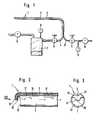
- Fig. 1 in schematischer Darstellung eine Vorrichtung zum Absaugen von Blutthromben aus Blutgefäßen,
- Fig. 2 in vergrößerter Darstellung und teilweise einen Schnitt durch einen Katheter des Gegenstandes nach Fig. 1,
- Fig. 3 eine Stirnansicht in Richtung des Pfeils III auf den Gegenstand nach Fig. 2.
- Fig. 4 eine andere Ausführung des Gegenstandes nach Fig. 2.
- 1 is a schematic representation of a device for suctioning blood thrombi from blood vessels,
- 2 is an enlarged view and partially a section through a catheter of the object of FIG. 1,
- 3 shows an end view in the direction of arrow III on the object according to FIG. 2.
- 4 shows another embodiment of the object according to FIG. 2.
Zu der dargestellten Vorrichtung gehört ein Katheter 1 mit einem Saugkanal 2 und einem Druckkanal 3. Der Saugkanal 2 und der Druckkanal 3 sind zumindest im Bereich des in das Blutgefäß einführbaren Teilstücks des Katheters 1 einstückig ausgeführt, wie das in Fig. 2 dargestellt ist. Über dieses Teilstück hinaus können Saugkanal 2 und Druckkanal 3 einstückig oder als gesonderte Leitungen ausgebildet sein. Bei der Ausführung nach Fig. 1 schließt an den Saugkanal 2 eine Saugleitung 4 an, die zu einer Vakuumpumpe 5 führt. In der Saugleitung 4 sind ein Druckregelventil 6 sowie ein Schauglas 7 mit einer Druckanzeige 8 angeordnet.The device shown includes a catheter 1 with a
An den Druckkanal 3 ist eine Druckleitung 9 angeschlossen, die zu einer Hochdruckpumpe 10 führt. Die Hochdruckpumpe ist für einen Druck von ca. 30 bar ausgelegt. In der Druckleitung 9 befindet sich ein Druckregelventil 11 und eine Druckanzeige 12.A pressure line 9 is connected to the
Aus einem Vergleich der Fig. 2 und 3 entnimmt man, daß im Bereich des in das Blutgefäß einzuführenden Teilstücks des Katheters 1 der Saugkanal 2 und der Druckkanal 3 parallel zueinander geführt sind. Der Querschnitt des Saugkanals 2 ist erheblich größer als der Querschnitt des Druckkanals 3. Der Druckkanal 3 ist bis über die freie Öffnung 13 des Saugkanals 2 geführt und endet dort in einer diese Öffnung 13 teilweise abdeckenden Zunge 14. An der Unterseite der Zunge 14 befindet sich eine Düse 15, die so ausgerichtet ist, daß die daraus austretenden Strahlen im wesentlichen in den Saugkanal 2 gerichtet sind. Außerdem sind in der gemeinsamen Wandung 16 zwischen Saugkanal 2 und Druckkanal 3 mehrere düsenartige Öffnungen 17, die bei der dargestellten Ausführung schräg zur Achse des Katheters so ausgerichtet sind, daß die daraus austretenden Strahlen den Transport im Saugkanal 2 unterstützen. Die Richtung der aus der Düse 15 bzw. den Öffnungen 17 austretenden Strahlen sind jeweils durch Pfeile angedeutet.A comparison of FIGS. 2 and 3 reveals that in the region of the section of the catheter 1 to be inserted into the blood vessel, the
Die dargestellte Vorrichtung funktioniert wie folgt: der Katheter 1 wird in das Blutgefäß eingeschoben, bis sein vorderes Ende mit der Zunge 14 unmittelbar vor dem Thrombus liegt. Nach Einschalten der Vakuumpumpe 5 wird der Thrombus in die Öffnung 13 eingesaugt. Eine Verstopfung der Öffnung 13 bzw. des Saugkanals 2 wird verhindert, wenn die Hochdruckpumpe 10 eingeschaltet wird und aus der Düse 15 ein Flüssigkeitsstrahl austritt, der den Thrombus ganz oder in Teilen in den Auskanal 2 hineintreibt. Beim Weitertransport des Thrombus oder seiner Teile durch den Saugkanal 2 treffen Teilstrahlen aus den düsenartigen Öffnungen 17 darauf, die nicht nur den Transport im Saugkanal 2 unterstützen sondern ggf. auch den Thrombus oder seine Teile weiterzerteilen.The device shown works as follows: the catheter 1 is inserted into the blood vessel until its front end with the
Durch Verstellung der Druckregelventile 6 bzw. 11 können die Strömungsverhältnisse im Katheter den jeweiligen Umständen angepaßt werden. Über das Schauglas 7 ist eine optische Kontrolle des abgesaugten Gutes möglich.By adjusting the pressure control valves 6 and 11, the flow conditions in the catheter can be adapted to the particular circumstances. A visual inspection of the extracted material is possible via the sight glass 7.
Bei der in Fig. 4 dargestellten Ausführung bezeichnen gleiche Bezugszeichen gleiche Teile. Dieser Katheter 1 ist insbesondere zum Entfernen von Nierensteinen, Gallensteinen und dergleichen geeignet. Sein Druckkanal 3 mit Zunge 14 besteht aus einer Kanüle 18, die in einem zugeordneten Führungskanal 19 des Katheters 1 längs verschieblich ist. Mit gestrichelten Linien ist die Kanüle 18 in ausgefahrener Stellung dargestellt, wobei zwischen der mit gestrichelten Linien dargestellten Zunge 14 und der Öffnung 13 des Saugkanals 2 ein mit gestrichelten Linien dargestellter Stein 20 gehalten ist. In der ausgefahrenen Stellung der Kanüle 18 kann das Ende des Katheters auch zum "Einfangen" eines Steins eingesetzt werden, der anschließend in der dargestellten Weise eingespannt wird. Der aus der Düse 15 austretende Flüssigkeitsstrahl zertrümmert den Stein 20, dessen Trümmer abgesaugt werden. Größere Trümmerstücke können wieder eingefangen und in der beschriebenen Weise zerkleinert und entfernt werden.In the embodiment shown in FIG. 4, the same reference numerals designate the same parts. This catheter 1 is particularly suitable for removing kidney stones, gall stones and the like. Its
Claims (9)
Translated fromGermanPriority Applications (1)
| Application Number | Priority Date | Filing Date | Title |
|---|---|---|---|
| AT85109361TATE39056T1 (en) | 1984-09-06 | 1985-07-25 | DEVICE FOR REMOVAL OF SOLIDS OR DEPOSITS FROM BODY VESSELS. |
Applications Claiming Priority (2)
| Application Number | Priority Date | Filing Date | Title |
|---|---|---|---|
| DE19848426270UDE8426270U1 (en) | 1984-09-06 | 1984-09-06 | DEVICE FOR REMOVING SOLID BODIES OR DEPOSITS FROM BODY VESSELS |
| DE8426270U | 1984-09-06 |
Publications (2)
| Publication Number | Publication Date |
|---|---|
| EP0175096A1true EP0175096A1 (en) | 1986-03-26 |
| EP0175096B1 EP0175096B1 (en) | 1988-12-07 |
Family
ID=6770448
Family Applications (1)
| Application Number | Title | Priority Date | Filing Date |
|---|---|---|---|
| EP85109361AExpiredEP0175096B1 (en) | 1984-09-06 | 1985-07-25 | Device for the removal of solid bodies or concrements from body vessels |
Country Status (5)
| Country | Link |
|---|---|
| US (1) | US4690672A (en) |
| EP (1) | EP0175096B1 (en) |
| JP (1) | JPS6168035A (en) |
| AT (1) | ATE39056T1 (en) |
| DE (2) | DE8426270U1 (en) |
Cited By (17)
| Publication number | Priority date | Publication date | Assignee | Title |
|---|---|---|---|---|
| US4825865A (en)* | 1987-05-01 | 1989-05-02 | Jerry Zelman | Apparatus and method for extracting cataract tissue |
| WO1990005493A1 (en)* | 1988-11-15 | 1990-05-31 | Svedman Paal | Surgical instrument |
| EP0442579A1 (en)* | 1990-02-14 | 1991-08-21 | Cordis Europa N.V. | Drainage catheter |
| US5057098A (en)* | 1987-05-01 | 1991-10-15 | Ophthalmocare, Inc. | Apparatus and method for extracting cataract tissue |
| US5112339A (en)* | 1990-06-18 | 1992-05-12 | Ophthalmocare, Inc. | Apparatus for extracting cataractous tissue |
| US5139504A (en)* | 1987-05-01 | 1992-08-18 | Ophthalmocare, Inc. | Apparatus, system, and method for softening and extracting cataractous tissue |
| EP0527312A1 (en)* | 1991-08-14 | 1993-02-17 | Convergenza Ag | Rinsing catheter |
| EP0533432A1 (en)* | 1991-09-17 | 1993-03-24 | Yamauchi, Teiyu | Catheter device |
| WO1994001157A1 (en)* | 1992-07-03 | 1994-01-20 | Harald Mang | Tracheal or tracheotomy tube and breathing installations fitted therewith |
| US5322504A (en)* | 1992-05-07 | 1994-06-21 | United States Surgical Corporation | Method and apparatus for tissue excision and removal by fluid jet |
| WO1995012421A1 (en)* | 1993-11-04 | 1995-05-11 | Ruggio Joseph M | Apparatus and method for aspirating intravascular, pulmonary and cardiac obstructions |
| US5453088A (en)* | 1993-04-13 | 1995-09-26 | Cordis Corporation | Hydrodynamic suction catheter |
| US5527330A (en)* | 1994-08-18 | 1996-06-18 | United States Surgical Corporation | Fluid cutting instrument |
| US5562692A (en)* | 1993-07-26 | 1996-10-08 | Sentinel Medical, Inc. | Fluid jet surgical cutting tool |
| US5591184A (en)* | 1994-10-13 | 1997-01-07 | Sentinel Medical, Inc. | Fluid jet surgical cutting instrument |
| US5735815A (en)* | 1993-07-26 | 1998-04-07 | Sentinel Medical, Inc. | Method of using fluid jet surgical cutting tool |
| US10363061B2 (en) | 2002-10-25 | 2019-07-30 | Hydrocision, Inc. | Nozzle assemblies for liquid jet surgical instruments and surgical instruments for employing the nozzle assemblies |
Families Citing this family (132)
| Publication number | Priority date | Publication date | Assignee | Title |
|---|---|---|---|---|
| US4772260A (en)* | 1986-05-02 | 1988-09-20 | Heyden Eugene L | Rectal catheter |
| DE3715418A1 (en)* | 1986-05-08 | 1987-11-12 | Olympus Optical Co | LITHOTOM |
| JPS6363450A (en)* | 1986-09-03 | 1988-03-19 | トノクラ医科工業株式会社 | Water jet operation apparatus |
| JPH0751062Y2 (en)* | 1989-01-13 | 1995-11-22 | 晴夫 高瀬 | Suction tube for removing biological tissue |
| US5797907A (en)* | 1989-11-06 | 1998-08-25 | Mectra Labs, Inc. | Electrocautery cutter |
| US5505210A (en)* | 1989-11-06 | 1996-04-09 | Mectra Labs, Inc. | Lavage with tissue cutting cannula |
| US5409013A (en)* | 1989-11-06 | 1995-04-25 | Mectra Labs, Inc. | Tissue removal assembly |
| US5335671A (en)* | 1989-11-06 | 1994-08-09 | Mectra Labs, Inc. | Tissue removal assembly with provision for an electro-cautery device |
| US5135484A (en)* | 1990-05-09 | 1992-08-04 | Pioneering Technologies, Inc. | Method of removing plaque from vessels |
| US6676627B1 (en)* | 1990-08-06 | 2004-01-13 | Possis Medical, Inc. | Crossflow thrombectomy catheter and system |
| US6984239B1 (en)* | 1990-08-06 | 2006-01-10 | Possis Medical, Inc. | Thrombectomy and tissue removal method |
| CA2048120A1 (en)* | 1990-08-06 | 1992-02-07 | William J. Drasler | Thrombectomy method and device |
| US5496267A (en)* | 1990-11-08 | 1996-03-05 | Possis Medical, Inc. | Asymmetric water jet atherectomy |
| US5129910A (en)* | 1991-07-26 | 1992-07-14 | The Regents Of The University Of California | Stone expulsion stent |
| DE4201992A1 (en)* | 1992-01-25 | 1993-07-29 | Hp Medica Gmbh Fuer Medizintec | HIGH PRESSURE LIQUID DISPENSOR FOR DISPENSING STERILE LIQUID |
| JP2580816Y2 (en)* | 1992-02-26 | 1998-09-17 | 晴夫 高瀬 | Suction tube for sucking tissue such as fat |
| AU5666694A (en)* | 1992-11-13 | 1994-06-08 | William J. Drasler | Thrombectomy and tissue removal method and device |
| US6193672B1 (en) | 1993-05-11 | 2001-02-27 | Mectra Labs, Inc. | Lavage |
| US6723069B1 (en)* | 1994-02-16 | 2004-04-20 | Novoste Corporation | Electrophysiology positioning catheter |
| US6135977A (en)* | 1994-02-16 | 2000-10-24 | Possis Medical, Inc. | Rheolytic catheter |
| US6017333A (en)* | 1995-04-13 | 2000-01-25 | Bailey; Robert W. | Irrigating laparoscopic cannula |
| US5846219A (en)* | 1994-05-26 | 1998-12-08 | Vancaillie; Thierry G. | Variable backflow suction-hydraulic curet |
| US6729334B1 (en)* | 1994-06-17 | 2004-05-04 | Trudell Medical Limited | Nebulizing catheter system and methods of use and manufacture |
| EP0954244A1 (en)* | 1994-07-01 | 1999-11-10 | SciMed Life Systems, Inc. | Intravascular device utilizing fluid to extract occlusive material |
| US5527332A (en)* | 1994-11-02 | 1996-06-18 | Mectra Labs, Inc. | Tissue cutter for surgery |
| US5520635A (en)* | 1994-12-16 | 1996-05-28 | Gelbfish; Gary A. | Method and associated device for removing clot |
| US5928218A (en)* | 1994-12-16 | 1999-07-27 | Gelbfish; Gary A. | Medical material removal method and associated instrumentation |
| US5871462A (en)* | 1995-06-07 | 1999-02-16 | Hydrocision, Inc. | Method for using a fluid jet cutting system |
| US5713878A (en)* | 1995-06-07 | 1998-02-03 | Surgi-Jet Corporation | Hand tightenable high pressure connector |
| US5944686A (en)* | 1995-06-07 | 1999-08-31 | Hydrocision, Inc. | Instrument for creating a fluid jet |
| US6216573B1 (en) | 1995-06-07 | 2001-04-17 | Hydrocision, Inc. | Fluid jet cutting system |
| US5843022A (en)* | 1995-10-25 | 1998-12-01 | Scimied Life Systems, Inc. | Intravascular device utilizing fluid to extract occlusive material |
| US7879022B2 (en)* | 1998-02-06 | 2011-02-01 | Medrad, Inc. | Rapid exchange fluid jet thrombectomy device and method |
| US6224570B1 (en)* | 1998-02-06 | 2001-05-01 | Possis Medical, Inc. | Rheolytic thrombectomy catheter and method of using same |
| US5989210A (en)* | 1998-02-06 | 1999-11-23 | Possis Medical, Inc. | Rheolytic thrombectomy catheter and method of using same |
| US9586023B2 (en) | 1998-02-06 | 2017-03-07 | Boston Scientific Limited | Direct stream hydrodynamic catheter system |
| US6527979B2 (en) | 1999-08-27 | 2003-03-04 | Corazon Technologies, Inc. | Catheter systems and methods for their use in the treatment of calcified vascular occlusions |
| US6290689B1 (en) | 1999-10-22 | 2001-09-18 | Corazón Technologies, Inc. | Catheter devices and methods for their use in the treatment of calcified vascular occlusions |
| US6375635B1 (en) | 1999-05-18 | 2002-04-23 | Hydrocision, Inc. | Fluid jet surgical instruments |
| US6709427B1 (en)* | 1999-08-05 | 2004-03-23 | Kensey Nash Corporation | Systems and methods for delivering agents into targeted tissue of a living being |
| JP2003522560A (en) | 1999-08-27 | 2003-07-29 | コラゾン テクノロジーズ, インコーポレイテッド | Catheter devices and their use in treating calcified vascular occlusion |
| US6533767B2 (en) | 2000-03-20 | 2003-03-18 | Corazon Technologies, Inc. | Methods for enhancing fluid flow through an obstructed vascular site, and systems and kits for use in practicing the same |
| US6451017B1 (en) | 2000-01-10 | 2002-09-17 | Hydrocision, Inc. | Surgical instruments with integrated electrocautery |
| US6511493B1 (en) | 2000-01-10 | 2003-01-28 | Hydrocision, Inc. | Liquid jet-powered surgical instruments |
| WO2001070320A1 (en) | 2000-03-20 | 2001-09-27 | Corazon Technologies, Inc. | Methods and systems for enhancing fluid flow through an obstructed vascular site |
| US6540733B2 (en)* | 2000-12-29 | 2003-04-01 | Corazon Technologies, Inc. | Proton generating catheters and methods for their use in enhancing fluid flow through a vascular site occupied by a calcified vascular occlusion |
| ES2290293T3 (en)* | 2001-04-27 | 2008-02-16 | Hydrocision, Inc. | HIGH PRESSURE PUMPING CARTRIDGES FOR MEDICAL AND SURGICAL PUMPING AND INFUSION APPLICATIONS. |
| DE60232664D1 (en)* | 2001-08-08 | 2009-07-30 | Hydrocision Inc | MEDICAL DEVICE WITH A HANDPIECE WITH A HIGH PRESSURE QUICK COUPLING |
| US20050021075A1 (en)* | 2002-12-30 | 2005-01-27 | Bonnette Michael J. | Guidewire having deployable sheathless protective filter |
| DE60221294T2 (en) | 2001-11-21 | 2008-04-03 | HydroCision, Inc., Billerica | SURGICAL LIQUID LIGHT INSTRUMENTS WITH CHANNEL OPENINGS ALONG THE BEAM |
| US6790196B2 (en) | 2001-12-18 | 2004-09-14 | Scimed Life Systems, Inc. | Aspirating devices for removal of thrombus/lipid from a body lumen |
| US7189250B2 (en)* | 2002-01-10 | 2007-03-13 | Scimed Life Systems, Inc. | Aspirating balloon catheter for treating vulnerable plaque |
| US7815596B2 (en)* | 2002-02-28 | 2010-10-19 | Cordis Corporation | Localized fluid delivery having a porous applicator and methods for using the same |
| US20030187495A1 (en) | 2002-04-01 | 2003-10-02 | Cully Edward H. | Endoluminal devices, embolic filters, methods of manufacture and use |
| US7179269B2 (en) | 2002-05-20 | 2007-02-20 | Scimed Life Systems, Inc. | Apparatus and system for removing an obstruction from a lumen |
| US20040093012A1 (en) | 2002-10-17 | 2004-05-13 | Cully Edward H. | Embolic filter frame having looped support strut elements |
| CA2502984A1 (en)* | 2002-10-25 | 2004-05-06 | Hydrocision, Inc. | Surgical devices incorporating liquid jet assisted tissue manipulation and methods for their use |
| US8162966B2 (en) | 2002-10-25 | 2012-04-24 | Hydrocision, Inc. | Surgical devices incorporating liquid jet assisted tissue manipulation and methods for their use |
| JP4409179B2 (en) | 2003-01-22 | 2010-02-03 | ニプロ株式会社 | Thrombus aspiration catheter with improved suction and crossability |
| US7794408B2 (en) | 2003-03-28 | 2010-09-14 | Ethicon, Inc. | Tissue collection device and methods |
| US20060129091A1 (en) | 2004-12-10 | 2006-06-15 | Possis Medical, Inc. | Enhanced cross stream mechanical thrombectomy catheter with backloading manifold |
| US8034003B2 (en) | 2003-09-11 | 2011-10-11 | Depuy Mitek, Inc. | Tissue extraction and collection device |
| US7611473B2 (en) | 2003-09-11 | 2009-11-03 | Ethicon, Inc. | Tissue extraction and maceration device |
| US7220269B1 (en)* | 2003-11-06 | 2007-05-22 | Possis Medical, Inc. | Thrombectomy catheter system with occluder and method of using same |
| JP2005147350A (en)* | 2003-11-19 | 2005-06-09 | Nikkiso Co Ltd | Microjet generator and thrombolysis device |
| US7740626B2 (en)* | 2003-11-21 | 2010-06-22 | Terumo Kabushiki Kaisha | Laser induced liquid jet generating apparatus |
| GB2411359A (en)* | 2004-02-28 | 2005-08-31 | David Hoyle | Vascular descaler |
| DE102004020855B4 (en)* | 2004-04-28 | 2009-06-10 | Erbe Elektromedizin Gmbh | Applicator for waterjet surgery |
| US7572244B2 (en)* | 2004-08-02 | 2009-08-11 | Medrad, Inc. | Miniature cross stream thrombectomy catheter |
| US20060100606A1 (en)* | 2004-11-10 | 2006-05-11 | Dobak John D Iii | Method and device for liposuction |
| US20060100569A1 (en)* | 2004-11-11 | 2006-05-11 | Depuy Mitek, Inc | Methods and devices for selective bulk removal and precision sculpting of tissue |
| US7632242B2 (en) | 2004-12-09 | 2009-12-15 | Boston Scientific Scimed, Inc. | Catheter including a compliant balloon |
| US20060129086A1 (en)* | 2004-12-13 | 2006-06-15 | Depuy Mitek, Inc. | Interchangeable tissue macerating and sculpting methods and devices |
| EP1707152A3 (en)* | 2005-03-29 | 2007-08-08 | Terumo Kabushiki Kaisha | Laser induced liquid jet generating device |
| GB2427142B (en)* | 2005-06-13 | 2010-10-20 | Single Use Surgical Ltd | Multi lumen suction irrigator |
| US20070060878A1 (en)* | 2005-09-01 | 2007-03-15 | Possis Medical, Inc. | Occlusive guidewire system having an ergonomic handheld control mechanism and torqueable kink-resistant guidewire |
| US8012117B2 (en) | 2007-02-06 | 2011-09-06 | Medrad, Inc. | Miniature flexible thrombectomy catheter |
| US20080188793A1 (en)* | 2007-02-06 | 2008-08-07 | Possis Medical, Inc. | Miniature flexible thrombectomy catheter |
| US8162878B2 (en)* | 2005-12-05 | 2012-04-24 | Medrad, Inc. | Exhaust-pressure-operated balloon catheter system |
| US7846175B2 (en)* | 2006-04-03 | 2010-12-07 | Medrad, Inc. | Guidewire and collapsable filter system |
| CN101460101A (en)* | 2006-04-25 | 2009-06-17 | 海德鲁西昂公司 | Electroformed liquid jet surgical instrument |
| US7951161B2 (en)* | 2006-05-09 | 2011-05-31 | Medrad, Inc. | Atherectomy system having a variably exposed cutter |
| US20080234722A1 (en)* | 2006-06-14 | 2008-09-25 | Possis Medical, Inc. | Inferior vena cava filter on guidewire |
| US9149609B2 (en)* | 2006-10-16 | 2015-10-06 | Embolitech, Llc | Catheter for removal of an organized embolic thrombus |
| CN101657163A (en)* | 2006-12-29 | 2010-02-24 | 史密夫和内修有限公司 | Wound bed preparation |
| EP2104460A2 (en)* | 2006-12-29 | 2009-09-30 | Vascure Ltd. | Atherectomy methods and apparatus |
| US8986326B2 (en) | 2007-01-26 | 2015-03-24 | Olympus Medical Systems Corp. | Gasper and grasping tool |
| EP3689274A1 (en) | 2007-02-05 | 2020-08-05 | Boston Scientific Limited | Thrombectomy system |
| US9254144B2 (en)* | 2007-03-30 | 2016-02-09 | Covidien Lp | Methods and apparatus for thrombectomy system |
| CA2685563A1 (en)* | 2007-04-30 | 2008-11-06 | Andrew Technologies Llc | Liposuction based on tissue liquefaction |
| US8366700B2 (en)* | 2007-04-30 | 2013-02-05 | Andrew Technologies, Llc | Liposuction of visceral fat using tissue liquefaction |
| US8974418B2 (en)* | 2007-06-12 | 2015-03-10 | Boston Scientific Limited | Forwardly directed fluid jet crossing catheter |
| US20080319386A1 (en)* | 2007-06-20 | 2008-12-25 | Possis Medical, Inc. | Forwardly directable fluid jet crossing catheter |
| JP2009072294A (en)* | 2007-09-19 | 2009-04-09 | Senko Medical Instr Mfg Co Ltd | Suction catheter |
| US9827084B2 (en) | 2007-10-26 | 2017-11-28 | Embolitech, Llc | Intravascular guidewire filter system for pulmonary embolism protection and embolism removal or maceration |
| WO2009079539A1 (en)* | 2007-12-17 | 2009-06-25 | Medrad, Inc. | Rheolytic thrombectomy catheter with self-inflation distal balloon |
| GB0724836D0 (en)* | 2007-12-20 | 2008-01-30 | Smith & Nephew | Waste control apparatus |
| EP2227285A4 (en)* | 2007-12-26 | 2013-07-31 | Medrad Inc | Rheolytic thrombectomy catheter with self-inflating proximal balloon with drug infusion capabilities |
| US8647294B2 (en) | 2008-03-20 | 2014-02-11 | Medrad, Inc. | Direct stream hydrodynamic catheter system |
| EA201001745A1 (en)* | 2008-05-20 | 2011-08-30 | Изиглайд Лтд. | ENDOSCOPIC DEVICE WITH CLEANING BY MEANS OF CURRENT MEDIUM |
| US9510854B2 (en) | 2008-10-13 | 2016-12-06 | Boston Scientific Scimed, Inc. | Thrombectomy catheter with control box having pressure/vacuum valve for synchronous aspiration and fluid irrigation |
| EP2395929A4 (en)* | 2009-02-11 | 2014-02-26 | Mark Mallaby | Neurovascular microcatheter device, system and methods for use thereof |
| WO2010146159A1 (en)* | 2009-06-18 | 2010-12-23 | Medizinische Universität Graz | Apparatus and method for sucking a fluid to be sucked |
| US8398579B2 (en) | 2009-12-16 | 2013-03-19 | Medrad, Inc. | Catheter including composite guide and methods for use of the same |
| US9308024B2 (en)* | 2010-03-11 | 2016-04-12 | Kci Licensing, Inc. | Tissue debridement systems and methods |
| US8475482B2 (en) | 2011-02-17 | 2013-07-02 | Gyrus Ent L.L.C. | Surgical instrument with distal suction capability |
| US9993585B2 (en)* | 2011-11-11 | 2018-06-12 | University Of Virginia Patent Foundation | Method suction device and related method thereof |
| US9204887B2 (en) | 2012-08-14 | 2015-12-08 | W. L. Gore & Associates, Inc. | Devices and systems for thrombus treatment |
| US20140228869A1 (en)* | 2013-02-13 | 2014-08-14 | Medrad, Inc. | Thrombectomy catheter |
| US20140277006A1 (en)* | 2013-03-14 | 2014-09-18 | Medrad, Inc. | Thrombectomy catheters, systems and methods |
| JP5597737B2 (en)* | 2013-03-15 | 2014-10-01 | 株式会社 先端医療開発 | Aspiration catheter |
| US9782195B2 (en)* | 2013-11-20 | 2017-10-10 | Board Of Regents Of The University Of Nebraska | Fluid jet arterial surgical device |
| US9248221B2 (en) | 2014-04-08 | 2016-02-02 | Incuvate, Llc | Aspiration monitoring system and method |
| US9433427B2 (en) | 2014-04-08 | 2016-09-06 | Incuvate, Llc | Systems and methods for management of thrombosis |
| US9883877B2 (en) | 2014-05-19 | 2018-02-06 | Walk Vascular, Llc | Systems and methods for removal of blood and thrombotic material |
| WO2015196156A1 (en)* | 2014-06-20 | 2015-12-23 | Boston Scientific Limited | Thrombectomy catheter system |
| US9730773B2 (en) | 2015-04-22 | 2017-08-15 | Maxillent Ltd. | Bone graft injection methods |
| WO2017019572A1 (en) | 2015-07-24 | 2017-02-02 | Ichor Vascular Inc. | Embolectomy system and methods of making same |
| US10702292B2 (en) | 2015-08-28 | 2020-07-07 | Incuvate, Llc | Aspiration monitoring system and method |
| US10561440B2 (en) | 2015-09-03 | 2020-02-18 | Vesatek, Llc | Systems and methods for manipulating medical devices |
| US20170100142A1 (en) | 2015-10-09 | 2017-04-13 | Incuvate, Llc | Systems and methods for management of thrombosis |
| US10226263B2 (en) | 2015-12-23 | 2019-03-12 | Incuvate, Llc | Aspiration monitoring system and method |
| US10492805B2 (en) | 2016-04-06 | 2019-12-03 | Walk Vascular, Llc | Systems and methods for thrombolysis and delivery of an agent |
| US10492821B2 (en) | 2016-06-24 | 2019-12-03 | Hydrocision, Inc. | Selective tissue removal treatment device |
| US10485568B2 (en) | 2016-06-24 | 2019-11-26 | Hydrocision, Inc. | Selective tissue removal treatment device |
| CN107865683A (en)* | 2016-09-27 | 2018-04-03 | 惠州科赛医疗有限公司 | Nozzle, water knife apparatus, nozzle forming method and water knife apparatus forming method |
| US10716880B2 (en) | 2018-06-15 | 2020-07-21 | Incuvate, Llc | Systems and methods for aspiration and monitoring |
| US11678905B2 (en) | 2018-07-19 | 2023-06-20 | Walk Vascular, Llc | Systems and methods for removal of blood and thrombotic material |
| CN111481262A (en)* | 2020-05-29 | 2020-08-04 | 上海融脉医疗科技有限公司 | A thrombus removal catheter structure |
| US12274458B2 (en) | 2021-02-15 | 2025-04-15 | Walk Vascular, Llc | Systems and methods for removal of blood and thrombotic material |
| JP2024506374A (en) | 2021-02-15 | 2024-02-13 | ウォーク バスキュラー, エルエルシー | System and method for removing blood and thrombotic material |
| US12280222B2 (en) | 2023-08-28 | 2025-04-22 | Incuvate, Llc | Systems and methods for injection and aspiration |
Citations (4)
| Publication number | Priority date | Publication date | Assignee | Title |
|---|---|---|---|---|
| US3542031A (en)* | 1968-06-24 | 1970-11-24 | Marshall B Taylor | Vacuum curette |
| DE2230283A1 (en)* | 1972-06-16 | 1974-01-03 | Fiesser Heinz Ulrich | DEVICE FOR REMOVAL OF URETIC STONES |
| DE2447513A1 (en)* | 1974-10-04 | 1976-04-08 | Henke Sass Wolf Gmbh | Suction curette for uterus evacuation or curettage - with continuous flushing of suction inlet especially with saline |
| DE3029042A1 (en)* | 1980-07-31 | 1982-02-18 | Storz, Karl, 7200 Tuttlingen | Blockage prevention for surgical drainage tube - uses support for cannula with pump, periodically injecting flushing liq. into drainage region |
Family Cites Families (5)
| Publication number | Priority date | Publication date | Assignee | Title |
|---|---|---|---|---|
| US1902418A (en)* | 1931-11-02 | 1933-03-21 | Jensen Salsbery Lab Inc | Surgical instrument |
| US2147652A (en)* | 1935-07-27 | 1939-02-21 | Rodney S Kennison | Nozzle |
| US2804075A (en)* | 1955-11-14 | 1957-08-27 | Ruth O Borden | Non-clogging surgical aspirator |
| US3429313A (en)* | 1966-02-01 | 1969-02-25 | Ram Domestic Products Co | Medical drainage pump |
| JPS5352685U (en)* | 1976-10-08 | 1978-05-06 |
- 1984
- 1984-09-06DEDE19848426270Upatent/DE8426270U1/ennot_activeExpired
- 1985
- 1985-07-25EPEP85109361Apatent/EP0175096B1/ennot_activeExpired
- 1985-07-25DEDE8585109361Tpatent/DE3566612D1/ennot_activeExpired
- 1985-07-25ATAT85109361Tpatent/ATE39056T1/ennot_activeIP Right Cessation
- 1985-09-05JPJP60195003Apatent/JPS6168035A/enactiveGranted
- 1986
- 1986-10-21USUS06/921,872patent/US4690672A/ennot_activeExpired - Lifetime
Patent Citations (4)
| Publication number | Priority date | Publication date | Assignee | Title |
|---|---|---|---|---|
| US3542031A (en)* | 1968-06-24 | 1970-11-24 | Marshall B Taylor | Vacuum curette |
| DE2230283A1 (en)* | 1972-06-16 | 1974-01-03 | Fiesser Heinz Ulrich | DEVICE FOR REMOVAL OF URETIC STONES |
| DE2447513A1 (en)* | 1974-10-04 | 1976-04-08 | Henke Sass Wolf Gmbh | Suction curette for uterus evacuation or curettage - with continuous flushing of suction inlet especially with saline |
| DE3029042A1 (en)* | 1980-07-31 | 1982-02-18 | Storz, Karl, 7200 Tuttlingen | Blockage prevention for surgical drainage tube - uses support for cannula with pump, periodically injecting flushing liq. into drainage region |
Cited By (25)
| Publication number | Priority date | Publication date | Assignee | Title |
|---|---|---|---|---|
| US5057098A (en)* | 1987-05-01 | 1991-10-15 | Ophthalmocare, Inc. | Apparatus and method for extracting cataract tissue |
| US5139504A (en)* | 1987-05-01 | 1992-08-18 | Ophthalmocare, Inc. | Apparatus, system, and method for softening and extracting cataractous tissue |
| US4825865A (en)* | 1987-05-01 | 1989-05-02 | Jerry Zelman | Apparatus and method for extracting cataract tissue |
| WO1990005493A1 (en)* | 1988-11-15 | 1990-05-31 | Svedman Paal | Surgical instrument |
| US5320599A (en)* | 1990-02-14 | 1994-06-14 | Cordis Corporation | Drainage catheter |
| EP0442579A1 (en)* | 1990-02-14 | 1991-08-21 | Cordis Europa N.V. | Drainage catheter |
| US5785678A (en)* | 1990-02-14 | 1998-07-28 | Cordis Corporation | Drainage catheter and method of using |
| US5395315A (en)* | 1990-02-14 | 1995-03-07 | Cordis Corporation | Drainage catheter |
| US5112339A (en)* | 1990-06-18 | 1992-05-12 | Ophthalmocare, Inc. | Apparatus for extracting cataractous tissue |
| EP0527312A1 (en)* | 1991-08-14 | 1993-02-17 | Convergenza Ag | Rinsing catheter |
| US5318518A (en)* | 1991-08-14 | 1994-06-07 | Hp Medica Gesellschaft Mbh Fur Medizintechnische Systeme | Irrigating catheter |
| EP0533432A1 (en)* | 1991-09-17 | 1993-03-24 | Yamauchi, Teiyu | Catheter device |
| US5322504A (en)* | 1992-05-07 | 1994-06-21 | United States Surgical Corporation | Method and apparatus for tissue excision and removal by fluid jet |
| AU677212B2 (en)* | 1992-07-03 | 1997-04-17 | Harald Mang | Tracheal or tracheotomy tube and breathing installations fitted therewith |
| WO1994001157A1 (en)* | 1992-07-03 | 1994-01-20 | Harald Mang | Tracheal or tracheotomy tube and breathing installations fitted therewith |
| US5453088A (en)* | 1993-04-13 | 1995-09-26 | Cordis Corporation | Hydrodynamic suction catheter |
| US5853384A (en)* | 1993-07-26 | 1998-12-29 | Surgijet, Inc. | Fluid jet surgical cutting tool and aspiration device |
| US5562692A (en)* | 1993-07-26 | 1996-10-08 | Sentinel Medical, Inc. | Fluid jet surgical cutting tool |
| US5735815A (en)* | 1993-07-26 | 1998-04-07 | Sentinel Medical, Inc. | Method of using fluid jet surgical cutting tool |
| WO1995012421A1 (en)* | 1993-11-04 | 1995-05-11 | Ruggio Joseph M | Apparatus and method for aspirating intravascular, pulmonary and cardiac obstructions |
| US5476450A (en)* | 1993-11-04 | 1995-12-19 | Ruggio; Joseph M. | Apparatus and method for aspirating intravascular, pulmonary and cardiac obstructions |
| US5527330A (en)* | 1994-08-18 | 1996-06-18 | United States Surgical Corporation | Fluid cutting instrument |
| US5591184A (en)* | 1994-10-13 | 1997-01-07 | Sentinel Medical, Inc. | Fluid jet surgical cutting instrument |
| US10363061B2 (en) | 2002-10-25 | 2019-07-30 | Hydrocision, Inc. | Nozzle assemblies for liquid jet surgical instruments and surgical instruments for employing the nozzle assemblies |
| US11432838B2 (en) | 2002-10-25 | 2022-09-06 | Hydrocision, Inc. | Nozzle assemblies for liquid jet surgical instruments and surgical instruments for employing the nozzle assemblies |
Also Published As
| Publication number | Publication date |
|---|---|
| EP0175096B1 (en) | 1988-12-07 |
| DE3566612D1 (en) | 1989-01-12 |
| US4690672A (en) | 1987-09-01 |
| JPS6168035A (en) | 1986-04-08 |
| JPH0566132B2 (en) | 1993-09-21 |
| DE8426270U1 (en) | 1985-02-14 |
| ATE39056T1 (en) | 1988-12-15 |
Similar Documents
| Publication | Publication Date | Title |
|---|---|---|
| EP0175096B1 (en) | Device for the removal of solid bodies or concrements from body vessels | |
| DE69630626T2 (en) | Catheter with filter and device for the removal of thrombi | |
| DE69533677T2 (en) | DEVICE FOR REMOVING FABRICS FROM THE BODY | |
| EP0527312B1 (en) | Rinsing catheter | |
| DE69507686T2 (en) | Device for cutting and dilating blood vessels | |
| DE69031733T2 (en) | DEVICE FOR PREVENTING SKIN WEAR IN A DEVICE FOR SUCTIONING FAT | |
| WO2001091827A1 (en) | Liposuction device | |
| EP0345518B1 (en) | Plastic suction cup | |
| DE3326648C2 (en) | Balloon catheter | |
| EP2251142B1 (en) | Disposable nozzle | |
| DE4004837C1 (en) | ||
| DE3835553C1 (en) | Method for automatic emptying and highly selective isolation of different fluids via the head space of a vessel in which the fluids are present in layered formation and apparatus for carrying out the method and for cleaning the vessel | |
| DE2729566C3 (en) | Stone catcher | |
| DE4209005A1 (en) | Instrument for removing layer of tissue - is formed by jet of water emitted through specially shaped needle | |
| DE2417580A1 (en) | METHOD AND DEVICE FOR DIRECTING A JET OF LIQUID, CONTAINING SOLID ABRASION PARTICLES, ON THE SURFACE OF A WORKPIECE | |
| WO1997017010A1 (en) | Method and device for rinsing | |
| DE2542426A1 (en) | DEVICE FOR FILTERING A FLUID | |
| DE202018006303U1 (en) | shaft instrument | |
| DE69409542T2 (en) | NOZZLE FOR SURFACE TREATMENT AND DEVICE AND METHOD FOR SURFACE TREATMENT WITH SUCH A NOZZLE | |
| EP1049500B1 (en) | Device for washing-out the bladder | |
| CH587044A5 (en) | Surgical apparatus for removing animal tissue - has pump providing pressurised pulsating stream of liquid | |
| CH660943A5 (en) | DEVICE FOR RELEASING BONES. | |
| DE10352296B4 (en) | End piece and method for the vacuum extraction of particle-laden liquids | |
| CH666016A5 (en) | METHOD OF SPLICING TEXTILE YARNS AND DEVICE FOR CARRYING OUT THE METHOD. | |
| DD239114A1 (en) | DEVICE FOR CHOLEDOCHOLITHIASIS OPERATIONS |
Legal Events
| Date | Code | Title | Description |
|---|---|---|---|
| PUAI | Public reference made under article 153(3) epc to a published international application that has entered the european phase | Free format text:ORIGINAL CODE: 0009012 | |
| AK | Designated contracting states | Kind code of ref document:A1 Designated state(s):AT BE CH DE FR GB IT LI LU NL SE | |
| 17P | Request for examination filed | Effective date:19860714 | |
| 17Q | First examination report despatched | Effective date:19871127 | |
| GRAA | (expected) grant | Free format text:ORIGINAL CODE: 0009210 | |
| AK | Designated contracting states | Kind code of ref document:B1 Designated state(s):AT BE CH DE FR GB IT LI LU NL SE | |
| REF | Corresponds to: | Ref document number:39056 Country of ref document:AT Date of ref document:19881215 Kind code of ref document:T | |
| REF | Corresponds to: | Ref document number:3566612 Country of ref document:DE Date of ref document:19890112 | |
| ET | Fr: translation filed | ||
| ITF | It: translation for a ep patent filed | ||
| GBT | Gb: translation of ep patent filed (gb section 77(6)(a)/1977) | ||
| PLBE | No opposition filed within time limit | Free format text:ORIGINAL CODE: 0009261 | |
| STAA | Information on the status of an ep patent application or granted ep patent | Free format text:STATUS: NO OPPOSITION FILED WITHIN TIME LIMIT | |
| 26N | No opposition filed | ||
| ITTA | It: last paid annual fee | ||
| PGFP | Annual fee paid to national office [announced via postgrant information from national office to epo] | Ref country code:LU Payment date:19930723 Year of fee payment:9 | |
| PGFP | Annual fee paid to national office [announced via postgrant information from national office to epo] | Ref country code:SE Payment date:19930726 Year of fee payment:9 | |
| EPTA | Lu: last paid annual fee | ||
| PG25 | Lapsed in a contracting state [announced via postgrant information from national office to epo] | Ref country code:LU Free format text:LAPSE BECAUSE OF NON-PAYMENT OF DUE FEES Effective date:19940725 | |
| PG25 | Lapsed in a contracting state [announced via postgrant information from national office to epo] | Ref country code:SE Effective date:19940726 | |
| EUG | Se: european patent has lapsed | Ref document number:85109361.7 Effective date:19950210 | |
| EUG | Se: european patent has lapsed | Ref document number:85109361.7 | |
| REG | Reference to a national code | Ref country code:CH Ref legal event code:PUE Owner name:DIPL.-ING. ELMAR M. VELTRUP TRANSFER- CORDIS CORPO | |
| REG | Reference to a national code | Ref country code:GB Ref legal event code:IF02 | |
| PGFP | Annual fee paid to national office [announced via postgrant information from national office to epo] | Ref country code:NL Payment date:20040704 Year of fee payment:20 | |
| PGFP | Annual fee paid to national office [announced via postgrant information from national office to epo] | Ref country code:FR Payment date:20040708 Year of fee payment:20 | |
| PGFP | Annual fee paid to national office [announced via postgrant information from national office to epo] | Ref country code:AT Payment date:20040713 Year of fee payment:20 | |
| PGFP | Annual fee paid to national office [announced via postgrant information from national office to epo] | Ref country code:GB Payment date:20040721 Year of fee payment:20 | |
| PGFP | Annual fee paid to national office [announced via postgrant information from national office to epo] | Ref country code:CH Payment date:20040729 Year of fee payment:20 | |
| PGFP | Annual fee paid to national office [announced via postgrant information from national office to epo] | Ref country code:DE Payment date:20040806 Year of fee payment:20 | |
| PGFP | Annual fee paid to national office [announced via postgrant information from national office to epo] | Ref country code:BE Payment date:20040909 Year of fee payment:20 | |
| PG25 | Lapsed in a contracting state [announced via postgrant information from national office to epo] | Ref country code:GB Free format text:LAPSE BECAUSE OF EXPIRATION OF PROTECTION Effective date:20050724 | |
| PG25 | Lapsed in a contracting state [announced via postgrant information from national office to epo] | Ref country code:NL Free format text:LAPSE BECAUSE OF EXPIRATION OF PROTECTION Effective date:20050725 | |
| BE20 | Be: patent expired | Owner name:*VELTRUP ELMAR Effective date:20050725 | |
| REG | Reference to a national code | Ref country code:GB Ref legal event code:PE20 | |
| REG | Reference to a national code | Ref country code:CH Ref legal event code:PL | |
| NLV7 | Nl: ceased due to reaching the maximum lifetime of a patent | Effective date:20050725 | |
| BE20 | Be: patent expired | Owner name:*VELTRUP ELMAR Effective date:20050725 |