EP0173547B1 - Container for accommodating two kinds of liquids - Google Patents
Container for accommodating two kinds of liquidsDownload PDFInfo
- Publication number
- EP0173547B1 EP0173547B1EP85305958AEP85305958AEP0173547B1EP 0173547 B1EP0173547 B1EP 0173547B1EP 85305958 AEP85305958 AEP 85305958AEP 85305958 AEP85305958 AEP 85305958AEP 0173547 B1EP0173547 B1EP 0173547B1
- Authority
- EP
- European Patent Office
- Prior art keywords
- skirt
- lid
- small cup
- cup
- main body
- Prior art date
- Legal status (The legal status is an assumption and is not a legal conclusion. Google has not performed a legal analysis and makes no representation as to the accuracy of the status listed.)
- Expired - Lifetime
Links
- 239000007788liquidSubstances0.000titleclaimsdescription34
- 238000007789sealingMethods0.000claimsdescription13
- 230000000994depressogenic effectEffects0.000claimsdescription4
- 230000000881depressing effectEffects0.000claimsdescription3
- 230000002093peripheral effectEffects0.000claimsdescription2
- 239000000203mixtureSubstances0.000description6
- 239000000853adhesiveSubstances0.000description5
- 230000001070adhesive effectEffects0.000description5
- XLYOFNOQVPJJNP-UHFFFAOYSA-NwaterSubstancesOXLYOFNOQVPJJNP-UHFFFAOYSA-N0.000description5
- 235000011389fruit/vegetable juiceNutrition0.000description4
- 229910052500inorganic mineralInorganic materials0.000description4
- 238000000034methodMethods0.000description4
- 239000011707mineralSubstances0.000description4
- 239000000654additiveSubstances0.000description3
- 230000000694effectsEffects0.000description3
- 229910052751metalInorganic materials0.000description3
- 239000002184metalSubstances0.000description3
- 235000015041whiskyNutrition0.000description3
- 244000248349Citrus limonSpecies0.000description2
- 235000005979Citrus limonNutrition0.000description2
- 230000000996additive effectEffects0.000description2
- 235000013532brandyNutrition0.000description2
- 238000002788crimpingMethods0.000description2
- 238000006073displacement reactionMethods0.000description2
- 230000002708enhancing effectEffects0.000description2
- 239000011521glassSubstances0.000description2
- 238000004519manufacturing processMethods0.000description2
- 238000012986modificationMethods0.000description2
- 230000004048modificationEffects0.000description2
- 238000012856packingMethods0.000description2
- 238000003825pressingMethods0.000description2
- 238000003860storageMethods0.000description2
- 229910000838Al alloyInorganic materials0.000description1
- 239000004698PolyethyleneSubstances0.000description1
- 229910052782aluminiumInorganic materials0.000description1
- XAGFODPZIPBFFR-UHFFFAOYSA-NaluminiumChemical compound[Al]XAGFODPZIPBFFR-UHFFFAOYSA-N0.000description1
- 238000011109contaminationMethods0.000description1
- 238000001816coolingMethods0.000description1
- 230000007423decreaseEffects0.000description1
- 230000003247decreasing effectEffects0.000description1
- 230000006866deteriorationEffects0.000description1
- 238000002474experimental methodMethods0.000description1
- 239000000796flavoring agentSubstances0.000description1
- 235000019634flavorsNutrition0.000description1
- 235000013305foodNutrition0.000description1
- 239000000463materialSubstances0.000description1
- 239000004033plasticSubstances0.000description1
- 229920003023plasticPolymers0.000description1
- 239000002985plastic filmSubstances0.000description1
- 229920000728polyesterPolymers0.000description1
- 229920001225polyester resinPolymers0.000description1
- 239000004645polyester resinSubstances0.000description1
- -1polyethylenePolymers0.000description1
- 229920000573polyethylenePolymers0.000description1
- 230000002265preventionEffects0.000description1
- 239000000565sealantSubstances0.000description1
- 238000010008shearingMethods0.000description1
- 239000007787solidSubstances0.000description1
- 229920003002synthetic resinPolymers0.000description1
- 239000000057synthetic resinSubstances0.000description1
- 239000005029tin-free steelSubstances0.000description1
Images


Classifications
- B—PERFORMING OPERATIONS; TRANSPORTING
- B65—CONVEYING; PACKING; STORING; HANDLING THIN OR FILAMENTARY MATERIAL
- B65D—CONTAINERS FOR STORAGE OR TRANSPORT OF ARTICLES OR MATERIALS, e.g. BAGS, BARRELS, BOTTLES, BOXES, CANS, CARTONS, CRATES, DRUMS, JARS, TANKS, HOPPERS, FORWARDING CONTAINERS; ACCESSORIES, CLOSURES, OR FITTINGS THEREFOR; PACKAGING ELEMENTS; PACKAGES
- B65D81/00—Containers, packaging elements, or packages, for contents presenting particular transport or storage problems, or adapted to be used for non-packaging purposes after removal of contents
- B65D81/32—Containers, packaging elements, or packages, for contents presenting particular transport or storage problems, or adapted to be used for non-packaging purposes after removal of contents for packaging two or more different materials which must be maintained separate prior to use in admixture
- B65D81/3216—Rigid containers disposed one within the other
- B65D81/3222—Rigid containers disposed one within the other with additional means facilitating admixture
Definitions
- the present inventionrelates to a container for liquids, more particularly to one for accommodating two kinds of liquids separately from each other until the contents are in use.
- Japanese Examined Utility Model Publication (Kokoku) No. 53-18138proposes a container in which a small cup-like plug accommodating one component therein is fit into an upper free opening of a main body accommodating another component.
- a lid provided with a cuttercovers an upper free opening of the plug. In use, the lid is pressed so the cutter breaks a thin bottom wall of the plug, whereby the component in the plug falls into the main body to mix together with it.
- This containerhowever, has the drawback in that the assembly of the plug and the lid requires great care due to their delicate structure. This makes automation of the production process difficult. In addition, the plug cannot be removed at once, making dispensing of the content troublesome.
- Japanese Examined Utility Model Publication (Kokoku) No. 52-51103discloses a container similar to the above, in which a cap provided with a cutter is utilized in place of the lid of the abovesaid container.
- the capis screwed down around a neck of a main body accommodating a first component and breaks a bottom wall of a plug accommodating a second component.
- This containerhas the same drawbacks as stated before.
- Japanese Unexamined Utility Model Publication (Kokai) No. 55-7788discloses a can for coffee in which a top wall is constituted as a double structure having inner and outer plates and the latter is provided with a knife for breaking the inner plate.
- the outer plateis pressed or struck down toward the inner plate.
- the knifebreaks the latter and an additive contained in a space between the two plates falls down into coffee contained in the can body.
- the canis turned upside down and a bottom wall thereof is opened in a usual manner.
- This canis not used for accommodating a liquid type additive in the space of the top wall due to lack of sealability between the inner and outer plates. Even for powdery or solid type additives, there may be a risk of contamination.
- the broken opening of the inner plateis small, the coffee mixture tends to remain in the space between the two plates upon pouring.
- Japanese Unexamined Utility Model Publication (Kokai) No. 58-21566proposes a container for two kinds of liquids comprising a cup-like main body for a first liquid and an inverted cup-like lid for a second liquid having an inward projection at a center of a bottom wall thereof. A diaphragm is sealingly provided between the two.
- this containeris simple in structure, manufacture is very difficult.
- the lid and the main bodymust be joined with the thin diaphragm therebetween while the liquids are contained therein.
- Japanese Unexamined Utility Model Publication (Kokai) No. 59-109678discloses a container comprising a main body for a first liquid and an easy removable lid with a tab.
- a small cup for a second liquidis attached to an inside surface of the lid.
- a bottom wall of the small cuphas a weakened line along the width thereof formed by a cut reinforced with an adhesive.
- the lidis raised up in a cantilever manner by the tab, whereby the lid is bent upward and simultaneously the bottom wall of the small cup is broken along the weakened line.
- This containerhowever, has a drawback in that a relatively large force is required to cause the breakage of the small cup because it occurs only after the lid is bent.
- US-A-4221291discloses a bottle with a compartmented closure which fits into the bottle neck with an outer skirt fitting over the neck rim, and contains a second liquid between a deformable outer top cap and a bottom wall which can be broken away in hinged fashion.
- An actuating rodprojects from the bottom wall up to the cap, so that presssure on the cap ruptures the bottom wall.
- the present inventionaddresses the problem of providing a container for two kinds of liquid that is easy to assemble, and provides reliable and consistent means for letting one liquid mix with the other as well as complete dispensing thereafter.
- a container for holding two kinds of liquids separatelycomprising:
- the skirt of the small cupmay be bent inwards along the entire periphery of a lower part thereof to engage with the entire periphery of the upper end of the main body and may be provided with a tab integrally extending from a part of the lower end thereof.
- the skirt of the small cuppreferably has at least two pairs of slits and/or score lines extending upward from the lower end of the skirt, while the slits and/or score lines of each pair is positioned in symmetry with each other relative to a diameter of the small cup passing through the tab.
- the slits and/or score linesare preferably inclined relative to a height thereof.
- the skirt of the small cupmay be provided with a notch at a position in the lower end thereof diametrically opposite to the tab.
- the lidhas a skirt extending downward from the entire periphery thereof.
- a height of the skirtis larger than that of the skirt of the small cup.
- a lower end of the latter skirtis spaced outward from an outer wall of the main body and resiliently displaceable close to and apart from the outer wall of the main body.
- a lower end of the skirt of the lidis bent inward to form a plurality of protrusions.
- a diameter of an imaginary circle passing through the innermost edge of the protrusionsis smaller than that of an imaginary circle along the lower edge of the skirt of the small cup.
- the main bodyhas at least a rib constituting a thread around a neck portion thereof.
- the skirt of the lidis threadedly engageable, along the inwardly bent portion thereof, with the rib to provide a liquid-tight sealing of the container.
- the skirt of the small cuppreferably has a plurality of slits extending upward from the lower end of the skirt.
- a main body 1is of a cup shape having a beaded upper edge 1a and is made, for example, of glass.
- the main body 1contains therein a first liquid A (e.g., mineral water or juice).
- a small cup 2is fitted in an upper free opening of the main body 1, which is made of a thin metal sheet of aluminum or the like and contains therein a second liquid (e.g., whisky, brandy, or other spirit).
- the small cup 2consists of a receptacle portion 3 having a smaller diameter toward a bottom wall thereof, a flange 4 extending outward from the entire periphery of an upper end of the receptacle portion 3, a skirt 5 extending downward from the entire periphery of an outer edge of the flange 4, and a tab 6 extending outward from a part of the lower edge of the skirt 5.
- the small cup 2sealingly covers the upper side of the main body 1 by engaging the flange 4 on the beaded edge 1a a of the main body 1 and inwardly crimping the skirt 5 along a lower periphery of the beaded edge 1a.
- a sealant 7may be applied between the beaded edge 1a a and the flange 4 and/or the skirt 5.
- the skirt 5has two pairs of slits 18 and a pair of score lines 19 extending upward from a lower end of the skirt 5 for easy removal of the small cup 2 from the main body 1, as shown in Figure 7.
- the slits 18 and score lines 19are preferably provided at symmetrical points on the skirt 6 relative to a diameter passing through the tab 6, more preferably in the vicinity of a root of the tab 6 and/or at the points where another diameter perpendicular to the symmetry line intersects the skirt 5.
- the number of pairs of the slits and/or the score linesis preferably more than three.
- the "score line”stands for a narrow groove provided on one side of a surface not reaching the opposite side of the surface.
- a notch 20is provided on the skirt 5 at a position diametrically opposite to the tab 6 ( Figure 9).
- a height h of the notch 20is preferably less than half a height of the skirt H for ensuring the sealing effect.
- a lid 8is provided for covering an upper free opening of the small cup 2.
- the lid 8is preferably made of a single or multi-layered synthetic resin sheet such as polyester or polyethylene, at least one of the layers having a good gas-barrier property, and is fixed on the flange 4 by means of heat sealing or an adhesive.
- a projection 9protrudes downward until a tip thereof reaches the vicinity of a bottom wall 3a of the receptacle portion 3.
- the projection 9is preferably of an elongated conical shape but may be of other shapes as well provided they are rigid in structure. In this embodiment, though the projection 9 is formed integrally with the lid 8, it may be manufactured separately from the latter and attached thereto by melt-adhesion or press-fitting.
- the lid 8has a corrugation 4a for facilitating deformation thereof to sufficiently lower the projection 9 when the depressing force is applied to the lid 8.
- a specified area 12is provided in the bottom wall 3a of the receptacle portion 3 partly bordered by a score line 11 for being easily broken by the pressing down of the projection 9.
- a recess 13is provided for receiving the tip of the depressed projection 9, whereby the projection 9 can effectively break the score line 11 when pressed down without lateral movement relative to the bottom wall 3a, even with slippage between the tip of the projection and the bottom wall 3a.
- the pattern and cut depth of the score tine 11may be arbitrarily determined, however, a part thereof to be broken at first preferably has a smaller radius of curvature to minimize breakage energy. Also, the score line 11 may have a pattern completely encircling the area 12. In this case, however, the recess 13 is preferably deviated from the center of the area 12 in order to prevent complete breakage along the score line and falling down of the broken piece into the main body.
- the first liquid Ais filled in the main body 1 in a known manner. Hot packing is the most preferable when the first liquid A is mineral water, juice, or the like from the viewpoint of prevention of the quality deterioration of the contents and the ease of the process.
- the small cup 2is fit to the upper free opening of the main body 1 while the receptacle portion 3 is inserted therein. Then, the skirt 5 is bent inward along a lower edge of the entire periphery of the beaded edge 1a a of the main body 1 so that the liquid-tight sealing is obtained above the main body 1.
- the second liquid Bis filled in the small cup 2 and the lid 8 is fit thereon while the projection 9 is directed downward.
- a liquid-tight seal between the small cup 2 and the lid 8is obtained by heat sealing or adhering the periphery of the lid 8 to the flange 4.
- the second liquid Bis filled in the small cup 2
- the lidis applied and sealed thereon
- the main body 1is filled with the first liquid A, covered with the small cup 2
- the liquid-tight seal therebetweenis attained by crimping the skirt 5 along the lower edge of the beaded edge 1a of the main body 1, as stated before.
- a covering label(not shown) indicating the contents, instructions for opening, and/or a trademark is preferably laid on the lid 8.
- a certain spacemay be provided between the center portions of the covering label and the lid 8.
- the covering labelis removed, if existing, and the lid 8 is depressed at the center portion downward by a finger so that a depression force is applied on the recess 13 of the bottom wall 3a of the small cup 2 by the tip of the projection 9.
- the score line 11 in the vicinity of the recess 13is broken.
- the breakage of the residual part of the score line 11follows thereto.
- the second liquid B contained in the small cup 3easily flows down and mixes with the first liquid A in the main body 1.
- the tab 6is pulled forward and then lifted upward by a finger, whereby the score line 19 provided in the vicinity of the root of the tab 6 begins to break.
- the breakagereaches the flange 4 beyond the skirt 5, the interior of the main body 1 is released from the slight vacuum usually created by cooling after hot packing.
- the force pulling up the tab 6works to remove the small cup 2 upward from the main body 1, whereby the lower end of the skirt 5 in the vicinity of the tab 6 climbs over the beaded edge 1a.
- the receptacle portion 3has a tapered profile with a smaller diameter directing downward and there is a sufficient gap between an outer wall of the small cup 2 and an inner wall of the main body 1, the small cup 2 can be easily and completely dismounted from the main body 1 along with the lid 8.
- the mixture of the liquids A and Bis not only easily poured to another receptacle but also one can drink it directly from the main body 1.
- the slit 18(or score line 19) is preferably inclined to a vertical line Y-Y along height H of the skirt 18 at an angle 6, where 8 is 30° ⁇ 8 ⁇ 60°, preferably about 45°.
- a height hmust be less than 1/2 of H as is the case of the notch 20.
- the V-shaped deformation of the slitcan be effected even by minimum force. Further, in the region closer to the tab relative to a center of the small cup, a stretching force is exerted to the skirt and, contrary thereto, in the region further from the tab, a compressive force is exerted. That is, provision of the slits 18 or score lines 19 is effective for decreasing the stretching force required for the removal of the small cup.
- the following tableshows the difference of forces necessary for removing the small cup from the main body between containers having small cups with slits of different inclination and number.
- the force caused by pulling up the tabis more effectively exerted thereon than the case of the perpendicular slit.
- the notchis also effective for opening operation of the container.
- liquids A and Bare mineral water and whisky, respectively, a whisky-and-water drink is obtained. If a lemon juice and a spirit are adopted, one can enjoy a lemon cocktail at any place and any time.
- the dimensions of the containerare as follows:
- the small cupis not limited to one having a tapered profile as shown in this embodiment, but may be of another shape provided a gap sufficient to remove the small cup from the main body is formed between the inner wall of the latter and the small cup.
- the structure according to this embodimentis very simple, a conventional process can be utilized for assembly thereof. Since the small cup can easily and completely be removed from the main body together with the lid, one can drink, at a desired rate, the mixture directly from the main body, emptying the main body completely. Since the small cup is accommodated within the main body, damage during transportation and storage can be minimized.
- the second embodimentcomprises a main body 21, a small cup 22, and a lid 28 corresponding, respectively, to the main body 1, the small cup 2, and the lid 8 of the first embodiment.
- the main body 21is a cup-shaped receptacle for accommodating a first liquid A, such as mineral water or juice.
- the main body 21is preferably made of glass or plastic and has a beaded edge 21a around the entire periphery of an upper free opening thereof.
- the small cup 22is preferably made of a thin metal sheet or a plastic sheet or a combination thereof and is provided with a receptacle portion 23 for accommodating a second liquid B, such as whisky, brandy, or another spirit.
- a flange 24extends outward from the entire periphery of the receptacle portion 23, and a skirt 25 extends downward from the entire periphery of the flange 24.
- the small cup 22is fit in the free opening of the main body 21 while the flange 24 is placed on an upper end 44 of the main body 21.
- a middle portion of the skirt 25is bent inward along a lower end of the beaded edge 21a by means of a crimper (not shown), whereby the interior of the main body 21 is sealed from the outer air.
- a suitable sealing element 27may be placed between the flange 24 and the upper end 44 of the main body 21. In place of the sealing element 27, a releasable adhesive may be applied thereto, provided it does not affect the contents.
- the skirt 25is different from the first embodiment in that it is provided with a plurality of slits 38 extending upward from the entire periphery of a lower end of the skirt 25, as illustrated in Figure 15, and lacks a tab for pulling up the small cup.
- a lower edge 25a of the skirt 25is expanded outward from an outer wall of the main body 21 and is easily resiliently displaceable in the direction indicated by an arrow X due to a function of the slits 38 when external force is applied thereon.
- the flexible lid 28preferably made of a thin metal sheet such as aluminum alloy or tin-free steel, covers an upper free opening of the small cup 22 by liquid-tight contact of an inner surace of a top wall 45 of the lid 28 with the flange 24 of the small cup 22 via an annular sealing element 41.
- the lid 28is provided with a projection 29 at a center thereof and annular corrugations on a top wall 45 thereof for easy downward displacement of the projection 29, as is the case of the first embodiment.
- the bottom wall 23a of the receptacle portion 23 of the small cup 22is provided with a specified area (not indicated) partly encircled by a score line and a recess which, respectively, are identical to those 12, 11, and 13 of the first embodiment.
- the lid 28expands so that a periphery portion of the top wall 45 extends outward over the flange 24 of the small cup 22 and downward from the entire periphery to form a skirt 28a covering an upper outer wall 21 b of the main body 21.
- the skirt 28ahas a plurality of inner protrusions 28b at proper distances from each other, each of which is formed by a deeply bent part of a periphery of a lower end of the skirt 28a ( Figure 17).
- a diameter d 1 of an imaginary circle passing through all the protrusions 28bmust be smaller than a diameter d 2 of another imaginary circle along a lower edge 25a of the skirt 25 of the small cup 22.
- the height h 1 from a top wall 45 to the upper edge of the protrusion 28bmust be larger than a height h 2 of the skirt 25.
- a plurality of spiral ribs 40are provided on the upper outer wall 21 b of the main body 21.
- the ribs 40are arranged at a pitch corresponding to that of the protrusion 28b.
- a level at which the ribs 40 are arrangedis decided so that, when the lid 28 is capped on the main body 21, a first screw engagement of the protrusion 28b with a lower surface of the rib 40 is achievable by twisting of the lid 28 in the proper direction.
- the assembly of the second embodimentis similar to that of the first except for capping of the lid 28.
- the cappingis carried out by fitting the small cup 22 already covered with the lid 28 on the main body 21 and twisting the lid 28 in the proper direction for screw engagement of the protrusion 28b with the rib 40 until the annular sealing element 41 provided between the inner surface of the top wall 45 of the lid 28 and the upper surface of the flange 24 is sufficiently pressed by the both of them to form a liquid-tight seal.
- the protrusion 28brides over the lower edge 25a of the skirt 25, while resiliently displacing it in the direction indicated by the arrow X in Figure 16. This displacement of the skirt 25 is enhanced by provision of the slits 38, even though the small cup 22 is made of a rather rigid material.
- the opening operation of the containeris carried out by pressing down the projection 29 to break the bottom wall 23a of the receptacle portion 23 and unscrewing the lid 28 in the direction reverse to that when assembling the container.
- the small cup 22is removed from the main body 21 together with the lid 28 due to hooking engagement of the protrusion 28b with the lower edge 25a of the skirt 25.
- the lid 28 with the small cup 22 attached theretocan be capped on the main body 21 in the same manner as stated above.
- the lid 28may be constituted by two pieces, i.e., a disc member 46 and an annular member 48.
- the projection 29is also prepared separately from the disc member 46 and fit in a recess 49 on the disc member 46.
- the two members 46 and 48are fixed by an adhesive such as polyester resin in peripheral regions 47 and 46a of the annular member 48 and the disc member 46, respectively.
Landscapes
- Engineering & Computer Science (AREA)
- Mechanical Engineering (AREA)
- Closures For Containers (AREA)
Description
- The present invention relates to a container for liquids, more particularly to one for accommodating two kinds of liquids separately from each other until the contents are in use.
- It is a widely used technique in such fields as photographic developers or adhesives to store two kinds of liquids separately from each other for mixing just before use. Recently, such the technique has also become popular in the food industry for maintaining flavor and aroma of individual components.
- Japanese Examined Utility Model Publication (Kokoku) No. 53-18138 proposes a container in which a small cup-like plug accommodating one component therein is fit into an upper free opening of a main body accommodating another component. A lid provided with a cutter covers an upper free opening of the plug. In use, the lid is pressed so the cutter breaks a thin bottom wall of the plug, whereby the component in the plug falls into the main body to mix together with it. This container, however, has the drawback in that the assembly of the plug and the lid requires great care due to their delicate structure. This makes automation of the production process difficult. In addition, the plug cannot be removed at once, making dispensing of the content troublesome.
- Japanese Examined Utility Model Publication (Kokoku) No. 52-51103 discloses a container similar to the above, in which a cap provided with a cutter is utilized in place of the lid of the abovesaid container. The cap is screwed down around a neck of a main body accommodating a first component and breaks a bottom wall of a plug accommodating a second component. This container has the same drawbacks as stated before.
- Japanese Unexamined Utility Model Publication (Kokai) No. 55-7788 discloses a can for coffee in which a top wall is constituted as a double structure having inner and outer plates and the latter is provided with a knife for breaking the inner plate. In use, the outer plate is pressed or struck down toward the inner plate. The knife breaks the latter and an additive contained in a space between the two plates falls down into coffee contained in the can body. Finally, the can is turned upside down and a bottom wall thereof is opened in a usual manner. This can, however, is not used for accommodating a liquid type additive in the space of the top wall due to lack of sealability between the inner and outer plates. Even for powdery or solid type additives, there may be a risk of contamination. Moreover, since the broken opening of the inner plate is small, the coffee mixture tends to remain in the space between the two plates upon pouring.
- Japanese Unexamined Utility Model Publication (Kokai) No. 58-21566 proposes a container for two kinds of liquids comprising a cup-like main body for a first liquid and an inverted cup-like lid for a second liquid having an inward projection at a center of a bottom wall thereof. A diaphragm is sealingly provided between the two. Although this container is simple in structure, manufacture is very difficult. The lid and the main body must be joined with the thin diaphragm therebetween while the liquids are contained therein.
- Japanese Unexamined Utility Model Publication (Kokai) No. 59-109678 discloses a container comprising a main body for a first liquid and an easy removable lid with a tab. A small cup for a second liquid is attached to an inside surface of the lid. A bottom wall of the small cup has a weakened line along the width thereof formed by a cut reinforced with an adhesive. In use, the lid is raised up in a cantilever manner by the tab, whereby the lid is bent upward and simultaneously the bottom wall of the small cup is broken along the weakened line. This container, however, has a drawback in that a relatively large force is required to cause the breakage of the small cup because it occurs only after the lid is bent.
- US-A-4221291 discloses a bottle with a compartmented closure which fits into the bottle neck with an outer skirt fitting over the neck rim, and contains a second liquid between a deformable outer top cap and a bottom wall which can be broken away in hinged fashion. An actuating rod projects from the bottom wall up to the cap, so that presssure on the cap ruptures the bottom wall.
- The present invention addresses the problem of providing a container for two kinds of liquid that is easy to assemble, and provides reliable and consistent means for letting one liquid mix with the other as well as complete dispensing thereafter.
- According to the invention, there is provided a container for holding two kinds of liquids separately, comprising:
- a main container body for holding a first liquid, having an upper end opening;
- a small cup for holding a second liquid, having a flange extending outwardly from substantially all of its upper periphery, a skirt extending downwardly from an outer part of the flange substantially all round it, and a bottom wall having a specified area at least partially bordered by a score line, the small cup being fitted into the upper opening of
- the main container body with the flange and skirt engaging around an upper periphery thereof, and
- a flexible lid for sealing an upper opening of the small cup, whereby the small cup may be broken at the specified area by depressing the lid;
characterised in that the lid has a projection extending towards the specified area for breaking the small cup, and the specified area has a recess for receiving a tip end of the projection when the lid is depressed. - The skirt of the small cup may be bent inwards along the entire periphery of a lower part thereof to engage with the entire periphery of the upper end of the main body and may be provided with a tab integrally extending from a part of the lower end thereof.
- The skirt of the small cup preferably has at least two pairs of slits and/or score lines extending upward from the lower end of the skirt, while the slits and/or score lines of each pair is positioned in symmetry with each other relative to a diameter of the small cup passing through the tab.
- The slits and/or score lines are preferably inclined relative to a height thereof.
- The skirt of the small cup may be provided with a notch at a position in the lower end thereof diametrically opposite to the tab.
- In another aspect of the present invention, the lid has a skirt extending downward from the entire periphery thereof. A height of the skirt is larger than that of the skirt of the small cup. A lower end of the latter skirt is spaced outward from an outer wall of the main body and resiliently displaceable close to and apart from the outer wall of the main body. A lower end of the skirt of the lid is bent inward to form a plurality of protrusions. A diameter of an imaginary circle passing through the innermost edge of the protrusions is smaller than that of an imaginary circle along the lower edge of the skirt of the small cup. The main body has at least a rib constituting a thread around a neck portion thereof. The skirt of the lid is threadedly engageable, along the inwardly bent portion thereof, with the rib to provide a liquid-tight sealing of the container.
- The skirt of the small cup preferably has a plurality of slits extending upward from the lower end of the skirt.
- Other objects and advantages of the present invention will be apparent from the description of the preferred embodiments of the present invention with reference to the accompanying drawings: wherein
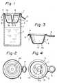
- Figure 1 is a side sectional view of a first embodiment of a container according to the present invention;
- Figure 2 is a top view of the first embodiment shown in Figure 1;
- Figures 3 and 4 are side sectional and top views of a small cup of the first embodiment, respectively;
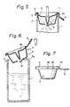
- Figure 5 is an explanatory view illustrating the breakage operation of the small cup;
- Figure 6 is an explanatory view illustration the removal operation of the small cup from a main body;
- Figure 7 is a side view of the small cup;
- Figure 8 is an enlarged partial view of a skirt of the small cup illustrating a slit provided thereon;
- Figure 9 is a front view of the small cup illustrating a notch provided on the skirt;
- Figures 10 through 13 are top view of the small cup illustrating various positions of the slits and/orthe notch on the skirt of the small cup, respectively;
- Figure 14 is a side sectional view of a second embodiment of a container according to the present invention;
- Figure 15 is a perspective view of a small cup of the second embodiment shown in Figure 14;
- Figure 16 is an enlarged partial view illustrating the connection between the respective parts of the container of the second embodiment;
- Figure 17 is a perspective view of a lid of the second embodiment;
- Figure 18 is a perspective view of a main body of the second embodiment; and
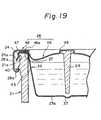
- Figure 19 is an enlarged partial view of a modification of the second embodiment illustrating the connection between the respective parts thereof.
- In a first embodiment of a container according to the present invention illustrated in Figures 1 through 7, a
main body 1 is of a cup shape having a beadedupper edge 1a and is made, for example, of glass. Themain body 1 contains therein a first liquid A (e.g., mineral water or juice). Asmall cup 2 is fitted in an upper free opening of themain body 1, which is made of a thin metal sheet of aluminum or the like and contains therein a second liquid (e.g., whisky, brandy, or other spirit). Thesmall cup 2 consists of areceptacle portion 3 having a smaller diameter toward a bottom wall thereof, aflange 4 extending outward from the entire periphery of an upper end of thereceptacle portion 3, askirt 5 extending downward from the entire periphery of an outer edge of theflange 4, and atab 6 extending outward from a part of the lower edge of theskirt 5. Thesmall cup 2 sealingly covers the upper side of themain body 1 by engaging theflange 4 on thebeaded edge 1a a of themain body 1 and inwardly crimping theskirt 5 along a lower periphery of thebeaded edge 1a. For enhancing the liquid-tight sealing, asealant 7 may be applied between thebeaded edge 1a a and theflange 4 and/or theskirt 5. - The
skirt 5 has two pairs ofslits 18 and a pair ofscore lines 19 extending upward from a lower end of theskirt 5 for easy removal of thesmall cup 2 from themain body 1, as shown in Figure 7. Theslits 18 and scorelines 19 are preferably provided at symmetrical points on theskirt 6 relative to a diameter passing through thetab 6, more preferably in the vicinity of a root of thetab 6 and/or at the points where another diameter perpendicular to the symmetry line intersects theskirt 5. The number of pairs of the slits and/or the score lines is preferably more than three. Here, the "score line" stands for a narrow groove provided on one side of a surface not reaching the opposite side of the surface. - A
notch 20 is provided on theskirt 5 at a position diametrically opposite to the tab 6 (Figure 9). A height h of thenotch 20 is preferably less than half a height of the skirt H for ensuring the sealing effect. - A
lid 8 is provided for covering an upper free opening of thesmall cup 2. Thelid 8 is preferably made of a single or multi-layered synthetic resin sheet such as polyester or polyethylene, at least one of the layers having a good gas-barrier property, and is fixed on theflange 4 by means of heat sealing or an adhesive. - In a center of the
lid 8, aprojection 9 protrudes downward until a tip thereof reaches the vicinity of abottom wall 3a of thereceptacle portion 3. Theprojection 9 is preferably of an elongated conical shape but may be of other shapes as well provided they are rigid in structure. In this embodiment, though theprojection 9 is formed integrally with thelid 8, it may be manufactured separately from the latter and attached thereto by melt-adhesion or press-fitting. - The
lid 8 has acorrugation 4a for facilitating deformation thereof to sufficiently lower theprojection 9 when the depressing force is applied to thelid 8. - A specified
area 12 is provided in thebottom wall 3a of thereceptacle portion 3 partly bordered by ascore line 11 for being easily broken by the pressing down of theprojection 9. In the specifiedarea 12, arecess 13 is provided for receiving the tip of thedepressed projection 9, whereby theprojection 9 can effectively break thescore line 11 when pressed down without lateral movement relative to thebottom wall 3a, even with slippage between the tip of the projection and thebottom wall 3a. - The pattern and cut depth of the
score tine 11 may be arbitrarily determined, however, a part thereof to be broken at first preferably has a smaller radius of curvature to minimize breakage energy. Also, thescore line 11 may have a pattern completely encircling thearea 12. In this case, however, therecess 13 is preferably deviated from the center of thearea 12 in order to prevent complete breakage along the score line and falling down of the broken piece into the main body. - Next, assembly of the container will be explained.
- At first, the first liquid A is filled in the
main body 1 in a known manner. Hot packing is the most preferable when the first liquid A is mineral water, juice, or the like from the viewpoint of prevention of the quality deterioration of the contents and the ease of the process. - The
small cup 2 is fit to the upper free opening of themain body 1 while thereceptacle portion 3 is inserted therein. Then, theskirt 5 is bent inward along a lower edge of the entire periphery of thebeaded edge 1a a of themain body 1 so that the liquid-tight sealing is obtained above themain body 1. - Thereafter, the second liquid B is filled in the
small cup 2 and thelid 8 is fit thereon while theprojection 9 is directed downward. A liquid-tight seal between thesmall cup 2 and thelid 8 is obtained by heat sealing or adhering the periphery of thelid 8 to theflange 4. - Alternatively, at first, the second liquid B is filled in the
small cup 2, the lid is applied and sealed thereon, and, thereafter, themain body 1 is filled with the first liquid A, covered with thesmall cup 2, and, finally, the liquid-tight seal therebetween is attained by crimping theskirt 5 along the lower edge of thebeaded edge 1a of themain body 1, as stated before. - During assembly, a covering label (not shown) indicating the contents, instructions for opening, and/or a trademark is preferably laid on the
lid 8. To avoid undesirable depression of theprojection 9 during storage, a certain space may be provided between the center portions of the covering label and thelid 8. - In use, the covering label is removed, if existing, and the
lid 8 is depressed at the center portion downward by a finger so that a depression force is applied on therecess 13 of thebottom wall 3a of thesmall cup 2 by the tip of theprojection 9. Thereby, thescore line 11 in the vicinity of therecess 13 is broken. Then, as a result of the increased shearing force caused by further downward movement of theprojection 9, the breakage of the residual part of thescore line 11 follows thereto. - Due to the above-mentioned breakage of the
area 12, the second liquid B contained in thesmall cup 3 easily flows down and mixes with the first liquid A in themain body 1. After the mixture of the two liquids A and B, thetab 6 is pulled forward and then lifted upward by a finger, whereby thescore line 19 provided in the vicinity of the root of thetab 6 begins to break. When the breakage reaches theflange 4 beyond theskirt 5, the interior of themain body 1 is released from the slight vacuum usually created by cooling after hot packing. The force pulling up thetab 6 works to remove thesmall cup 2 upward from themain body 1, whereby the lower end of theskirt 5 in the vicinity of thetab 6 climbs over thebeaded edge 1a. This is followed by widening of the width of theslits 18 and by releasing of the tight engagement between theskirt 5 and thebeaded edge 1a. Thenotch 20 enhances the easy removal of theskirt 5 from themain body 1 at the final stage of the operation. In this embodiment, since thereceptacle portion 3 has a tapered profile with a smaller diameter directing downward and there is a sufficient gap between an outer wall of thesmall cup 2 and an inner wall of themain body 1, thesmall cup 2 can be easily and completely dismounted from themain body 1 along with thelid 8. Thus, the mixture of the liquids A and B is not only easily poured to another receptacle but also one can drink it directly from themain body 1. - The effect of the
slit 18 and/or thescore line 19 will be explained in more detail as follows with reference to Figure 8. - The slit 18 (or score line 19) is preferably inclined to a vertical line Y-Y along height H of the
skirt 18 at anangle 6, where 8 is 30°<8<60°, preferably about 45°. A height h must be less than 1/2 of H as is the case of thenotch 20. According to the inventors' experiment, when a force is imparted on aportion 15 where theslit 18 is to be provided by pulling up thetab 6 in the direction indicated by an arrow F, the largest stress is generated in the direction of Z-Z (9=45°) and subsequently decreases in the directions of Y-Y and X-X. Thus, if the slit is provided in the direction of Z-Z or Z'-Z', the V-shaped deformation of the slit can be effected even by minimum force. Further, in the region closer to the tab relative to a center of the small cup, a stretching force is exerted to the skirt and, contrary thereto, in the region further from the tab, a compressive force is exerted. That is, provision of theslits 18 or scorelines 19 is effective for decreasing the stretching force required for the removal of the small cup. The following table shows the difference of forces necessary for removing the small cup from the main body between containers having small cups with slits of different inclination and number.
- According to the inclined slit or score line, the force caused by pulling up the tab is more effectively exerted thereon than the case of the perpendicular slit. Further, the notch is also effective for opening operation of the container.
- For example, if the liquids A and B are mineral water and whisky, respectively, a whisky-and-water drink is obtained. If a lemon juice and a spirit are adopted, one can enjoy a lemon cocktail at any place and any time.
- According to one example of the present invention, the dimensions of the container are as follows:

- The small cup is not limited to one having a tapered profile as shown in this embodiment, but may be of another shape provided a gap sufficient to remove the small cup from the main body is formed between the inner wall of the latter and the small cup.
- Since the structure according to this embodiment is very simple, a conventional process can be utilized for assembly thereof. Since the small cup can easily and completely be removed from the main body together with the lid, one can drink, at a desired rate, the mixture directly from the main body, emptying the main body completely. Since the small cup is accommodated within the main body, damage during transportation and storage can be minimized.
- A second embodiment of the present invention will be explained with reference to Figures 14 through 19.
- The second embodiment comprises a
main body 21, asmall cup 22, and alid 28 corresponding, respectively, to themain body 1, thesmall cup 2, and thelid 8 of the first embodiment. Themain body 21 is a cup-shaped receptacle for accommodating a first liquid A, such as mineral water or juice. Themain body 21 is preferably made of glass or plastic and has a beadededge 21a around the entire periphery of an upper free opening thereof. Thesmall cup 22 is preferably made of a thin metal sheet or a plastic sheet or a combination thereof and is provided with areceptacle portion 23 for accommodating a second liquid B, such as whisky, brandy, or another spirit. Aflange 24 extends outward from the entire periphery of thereceptacle portion 23, and askirt 25 extends downward from the entire periphery of theflange 24. Thesmall cup 22 is fit in the free opening of themain body 21 while theflange 24 is placed on anupper end 44 of themain body 21. A middle portion of theskirt 25 is bent inward along a lower end of thebeaded edge 21a by means of a crimper (not shown), whereby the interior of themain body 21 is sealed from the outer air. For enhancing the sealing effect, asuitable sealing element 27 may be placed between theflange 24 and theupper end 44 of themain body 21. In place of the sealingelement 27, a releasable adhesive may be applied thereto, provided it does not affect the contents. - The
skirt 25 is different from the first embodiment in that it is provided with a plurality ofslits 38 extending upward from the entire periphery of a lower end of theskirt 25, as illustrated in Figure 15, and lacks a tab for pulling up the small cup. - As shown in Figures 14 and 16, a
lower edge 25a of theskirt 25 is expanded outward from an outer wall of themain body 21 and is easily resiliently displaceable in the direction indicated by an arrow X due to a function of theslits 38 when external force is applied thereon. - The
flexible lid 28, preferably made of a thin metal sheet such as aluminum alloy or tin-free steel, covers an upper free opening of thesmall cup 22 by liquid-tight contact of an inner surace of atop wall 45 of thelid 28 with theflange 24 of thesmall cup 22 via anannular sealing element 41. - The
lid 28 is provided with aprojection 29 at a center thereof and annular corrugations on atop wall 45 thereof for easy downward displacement of theprojection 29, as is the case of the first embodiment. - Also, the
bottom wall 23a of thereceptacle portion 23 of thesmall cup 22 is provided with a specified area (not indicated) partly encircled by a score line and a recess which, respectively, are identical to those 12, 11, and 13 of the first embodiment. - As shown in Figure 16, the
lid 28 expands so that a periphery portion of thetop wall 45 extends outward over theflange 24 of thesmall cup 22 and downward from the entire periphery to form askirt 28a covering an upper outer wall 21 b of themain body 21. Theskirt 28a has a plurality ofinner protrusions 28b at proper distances from each other, each of which is formed by a deeply bent part of a periphery of a lower end of theskirt 28a (Figure 17). When themain body 21 and thesmall cup 22 are sealingly engaged with each other, a diameter d1 of an imaginary circle passing through all theprotrusions 28b must be smaller than a diameter d2 of another imaginary circle along alower edge 25a of theskirt 25 of thesmall cup 22. Further, the height h1 from atop wall 45 to the upper edge of theprotrusion 28b must be larger than a height h2 of theskirt 25. - As shown in Figure 18, a plurality of
spiral ribs 40 are provided on the upper outer wall 21 b of themain body 21. Theribs 40 are arranged at a pitch corresponding to that of theprotrusion 28b. A level at which theribs 40 are arranged is decided so that, when thelid 28 is capped on themain body 21, a first screw engagement of theprotrusion 28b with a lower surface of therib 40 is achievable by twisting of thelid 28 in the proper direction. - The assembly of the second embodiment is similar to that of the first except for capping of the
lid 28. The capping is carried out by fitting thesmall cup 22 already covered with thelid 28 on themain body 21 and twisting thelid 28 in the proper direction for screw engagement of theprotrusion 28b with therib 40 until theannular sealing element 41 provided between the inner surface of thetop wall 45 of thelid 28 and the upper surface of theflange 24 is sufficiently pressed by the both of them to form a liquid-tight seal. During the capping operation, theprotrusion 28b rides over thelower edge 25a of theskirt 25, while resiliently displacing it in the direction indicated by the arrow X in Figure 16. This displacement of theskirt 25 is enhanced by provision of theslits 38, even though thesmall cup 22 is made of a rather rigid material. - According to the second embodiment of the present invention, the opening operation of the container is carried out by pressing down the
projection 29 to break thebottom wall 23a of thereceptacle portion 23 and unscrewing thelid 28 in the direction reverse to that when assembling the container. By pulling up thelid 28, thesmall cup 22 is removed from themain body 21 together with thelid 28 due to hooking engagement of theprotrusion 28b with thelower edge 25a of theskirt 25. If one wishes to store any undrunk mixture after opening the container, thelid 28 with thesmall cup 22 attached thereto can be capped on themain body 21 in the same manner as stated above. Thus, even if the container falls, the contents are safely kept without leakage because thelid 28 and themain body 21 are liquid-tightly sealed by the screw engagement of therib 40 and theprotrusion 28b. - As shown in Figure 19, the
lid 28 may be constituted by two pieces, i.e., adisc member 46 and anannular member 48. In this modification, theprojection 29 is also prepared separately from thedisc member 46 and fit in arecess 49 on thedisc member 46. The twomembers peripheral regions annular member 48 and thedisc member 46, respectively.


Claims (7)
characterised in that the lid (8, 28) has a projection (9, 29) extending towards the specified area (12), for breaking the small cup (2, 22), and the specified area (12) has a recess (13,33) for receiving a tip end of the projection (9, 29) when the lid is depressed.
Applications Claiming Priority (10)
| Application Number | Priority Date | Filing Date | Title |
|---|---|---|---|
| JP127349/84 | 1984-08-22 | ||
| JP12734984UJPS6143170U (en) | 1984-08-22 | 1984-08-22 | liquid storage container |
| JP127790/84 | 1984-08-23 | ||
| JP12779084UJPS6143171U (en) | 1984-08-23 | 1984-08-23 | two-component storage container |
| JP14515584UJPH021267Y2 (en) | 1984-09-26 | 1984-09-26 | |
| JP145155/84 | 1984-09-26 | ||
| JP1984146896UJPH0219409Y2 (en) | 1984-09-28 | 1984-09-28 | |
| JP146896/84 | 1984-09-28 | ||
| JP60130812AJPS624056A (en) | 1985-06-18 | 1985-06-18 | Two liquid housing vessel |
| JP130812/85 | 1985-06-18 |
Publications (3)
| Publication Number | Publication Date |
|---|---|
| EP0173547A2 EP0173547A2 (en) | 1986-03-05 |
| EP0173547A3 EP0173547A3 (en) | 1987-11-11 |
| EP0173547B1true EP0173547B1 (en) | 1990-06-13 |
Family
ID=27527135
Family Applications (1)
| Application Number | Title | Priority Date | Filing Date |
|---|---|---|---|
| EP85305958AExpired - LifetimeEP0173547B1 (en) | 1984-08-22 | 1985-08-22 | Container for accommodating two kinds of liquids |
Country Status (3)
| Country | Link |
|---|---|
| US (1) | US4634003A (en) |
| EP (1) | EP0173547B1 (en) |
| DE (1) | DE3578159D1 (en) |
Cited By (5)
| Publication number | Priority date | Publication date | Assignee | Title |
|---|---|---|---|---|
| WO2014066704A1 (en)* | 2012-10-24 | 2014-05-01 | Genmark Diagnostics, Inc. | Integrated multiplex target analysis |
| US9222623B2 (en) | 2013-03-15 | 2015-12-29 | Genmark Diagnostics, Inc. | Devices and methods for manipulating deformable fluid vessels |
| US9498778B2 (en) | 2014-11-11 | 2016-11-22 | Genmark Diagnostics, Inc. | Instrument for processing cartridge for performing assays in a closed sample preparation and reaction system |
| US9598722B2 (en) | 2014-11-11 | 2017-03-21 | Genmark Diagnostics, Inc. | Cartridge for performing assays in a closed sample preparation and reaction system |
| US10005080B2 (en) | 2014-11-11 | 2018-06-26 | Genmark Diagnostics, Inc. | Instrument and cartridge for performing assays in a closed sample preparation and reaction system employing electrowetting fluid manipulation |
Families Citing this family (86)
| Publication number | Priority date | Publication date | Assignee | Title |
|---|---|---|---|---|
| DE3764371D1 (en)* | 1986-02-03 | 1990-09-27 | Toess Steigmuehle Ag | CONTAINER AND ITS APPLICATION. |
| GB2211479B (en)* | 1987-10-29 | 1992-02-26 | Price E J | Drinks container |
| GB2211478B (en)* | 1987-10-29 | 1992-01-22 | Price E J | Drinks container |
| US5384139A (en)* | 1988-06-24 | 1995-01-24 | Denis France | Method for the preservation of food compositions of the pancake, fritter and similar paste type |
| DE3872242D1 (en)* | 1988-12-14 | 1992-07-23 | Niederrheinische Blechwarenfab | PACKAGING FOR TWO-COMPONENT PRODUCTS. |
| GB2238767B (en)* | 1989-12-06 | 1993-10-20 | Femcare Ltd | Medical sponge system |
| US5035320A (en)* | 1990-05-07 | 1991-07-30 | Clifford Plone | Dispenser system with elongated selectively activatable dispensing pusher |
| US5147337A (en)* | 1990-05-07 | 1992-09-15 | Clifford Plone | Medicament dispenser |
| US5114011A (en)* | 1990-08-31 | 1992-05-19 | Robbins Edward S Iii | Container assemblies with additive cups |
| AU659617B2 (en)* | 1990-08-31 | 1995-05-25 | Edward S. Robbins Iii | Collapsible container and related method and apparatus |
| WO1993017928A1 (en)* | 1992-03-02 | 1993-09-16 | Isidro Genesca Romeu | Container for mixing a soluble powder extract and water |
| US5447236A (en)* | 1994-03-22 | 1995-09-05 | The Pillsbury Company | Multiple compartment package |
| US5514394A (en)* | 1994-07-29 | 1996-05-07 | Lenahan; Robert F. | Cereal package |
| US5741534A (en)* | 1994-08-26 | 1998-04-21 | Alice H. Chung | Packaged food product using partitioned receptacles with removable thin partition walls and method of making it |
| US5885635A (en)* | 1996-02-20 | 1999-03-23 | Canning Concepts, Inc. | Apparatus for dispersing a substance in a liquid beverage |
| WO1997029965A1 (en) | 1996-02-20 | 1997-08-21 | Canning Concepts, Inc. | Apparatus for dispensing a substance |
| DE19621774C2 (en)* | 1996-05-30 | 1999-11-18 | Juergen Otto | Device for preparing a mixture of an active substance and a diluent, and method for filling a cartridge for such a device |
| FR2759975B1 (en)* | 1997-02-25 | 1999-07-09 | Michel Bras | PROCESS FOR ASSEMBLING TWO CONTAINERS OF TWO SUBSTANCES INTENDED TO BE MIXED THEN CONSUMED |
| FR2759980A1 (en)* | 1997-02-25 | 1998-08-28 | Bras Michel | Container for mixable food ingredients |
| US6193058B1 (en) | 1999-03-05 | 2001-02-27 | Canberra Corportion | System for dispensing premeasured quantities of concentrated materials |
| US6159513A (en)* | 1999-05-27 | 2000-12-12 | Mott's, Inc. | Package and method for packaging and preparing a mixed drink |
| IL133778A (en)* | 1999-12-29 | 2003-03-12 | Nechama Shaki | Aroma-preserving canister for coffee and other granulated products |
| US6290100B1 (en) | 2000-06-30 | 2001-09-18 | Canberra Corporation | Concentrate cartridge for a diluting and dispensing container |
| US20050087458A1 (en)* | 2000-10-31 | 2005-04-28 | Richards Randall G. | Compartmentalized storage system for temporarily storing and subsequently mixing at least two different substances |
| US6302268B1 (en)* | 2000-11-24 | 2001-10-16 | Daniel Reuven Michaeli | Salad container having insert chamber |
| US6533113B2 (en) | 2000-12-01 | 2003-03-18 | Brett Moscovitz | System, devices and methods for storing and mixing substances |
| US6527110B2 (en) | 2000-12-01 | 2003-03-04 | Brett Moscovitz | Device for storing and dispensing a substance by mating with a container and associated methods |
| US20020157970A1 (en)* | 2001-04-26 | 2002-10-31 | Carlson Stephen G. | Beverage flavor dispensing cap |
| FR2826942A1 (en) | 2001-07-05 | 2003-01-10 | Brevet Michel Sarl | WALL FOR CLOSING A CONTAINER AND METHODS FOR ASSEMBLING CONTAINERS USING SUCH A WALL |
| US7850005B2 (en) | 2001-07-05 | 2010-12-14 | Interpharm Development | Separation container with interdisposed membrane |
| WO2003034038A2 (en)* | 2001-10-19 | 2003-04-24 | Monogen, Inc. | Flow control metering system and method for controlling filtration of liquid-based specimens |
| US6976578B1 (en)* | 2002-05-07 | 2005-12-20 | Antony Austin Kenihan | Dispensing lid closure for beverage container and method of making and using the closure |
| US7482116B2 (en) | 2002-06-07 | 2009-01-27 | Dna Genotek Inc. | Compositions and methods for obtaining nucleic acids from sputum |
| ES2255353B1 (en)* | 2003-07-29 | 2007-02-16 | Griffith Laboratories, S.A. | CONTAINER COVER FOR PACKAGING. |
| JP4519841B2 (en)* | 2003-07-30 | 2010-08-04 | エルエム、ベタイリグングス、アクチエンゲゼルシャフト | Synthetic resin beverage bottles with capsules |
| US7086549B2 (en)* | 2004-01-16 | 2006-08-08 | Illinois Tool Works Inc. | Fluid supply assembly |
| US7665672B2 (en)* | 2004-01-16 | 2010-02-23 | Illinois Tool Works Inc. | Antistatic paint cup |
| US7165732B2 (en)* | 2004-01-16 | 2007-01-23 | Illinois Tool Works Inc. | Adapter assembly for a fluid supply assembly |
| US7380680B2 (en) | 2004-01-16 | 2008-06-03 | Illinois Tool Works Inc. | Fluid supply assembly |
| US20050258271A1 (en)* | 2004-05-18 | 2005-11-24 | Kosmyna Michael J | Disposable paint cup |
| US7766250B2 (en) | 2004-06-01 | 2010-08-03 | Illinois Tool Works Inc. | Antistatic paint cup |
| US7354074B2 (en)* | 2004-06-03 | 2008-04-08 | Illinois Tool Works Inc. | Adapter assembly for a fluid supply assembly |
| US7757972B2 (en)* | 2004-06-03 | 2010-07-20 | Illinois Tool Works Inc. | Conversion adapter for a fluid supply assembly |
| US7353964B2 (en)* | 2004-06-10 | 2008-04-08 | Illinois Tool Works Inc. | Fluid supply assembly |
| GB0423237D0 (en)* | 2004-10-19 | 2004-11-24 | Pandrol Ltd | Railway track construction shims and method of constructing railway track |
| US20060113201A1 (en)* | 2004-12-01 | 2006-06-01 | Milojko Micic | Refillable drink bottle with replaceable concentrate container |
| CA2595531A1 (en)* | 2005-01-31 | 2006-08-03 | Illinois Tool Works Inc. | Fluid supply assembly with measuring guide |
| WO2006083871A2 (en)* | 2005-02-01 | 2006-08-10 | Guataplast, S.A. | Limited use-disposable salad container assembly |
| EP1874648B1 (en)* | 2005-04-19 | 2009-10-28 | Ekberg Emballage AB | Closure arrangement |
| US9211030B2 (en)* | 2005-10-20 | 2015-12-15 | Conagra Foods Rdm, Inc. | Steam cooking apparatus |
| US8302528B2 (en) | 2005-10-20 | 2012-11-06 | Conagra Foods Rdm, Inc. | Cooking method and apparatus |
| US9132951B2 (en) | 2005-11-23 | 2015-09-15 | Conagra Foods Rdm, Inc. | Food tray |
| CA2527770C (en) | 2005-11-21 | 2014-07-22 | Steven M. Parsons | Food tray |
| DE202005018847U1 (en)* | 2005-12-01 | 2007-04-12 | Hassia Verpackung Ag | Packaging for liquids for insertion in drinks preparation appliances consists of beaker-like lower part, lid connected to upper edge of beaker, cavity in bottom of lower part with puncturable, membrane-like bottom |
| GB0601018D0 (en)* | 2006-01-18 | 2006-03-01 | Carbonite Corp | Inserts for multiple component containers |
| US7681726B2 (en)* | 2006-08-15 | 2010-03-23 | O'donnell Brian | Apparatus for internal mixture of substances |
| US8453833B2 (en)* | 2006-08-15 | 2013-06-04 | Granite State Product Development LLC | Apparatus for internal mixture of substances |
| US20080099506A1 (en)* | 2006-10-25 | 2008-05-01 | Yo! Brands, Llc | Liquid dispenser having multi-chamber interior liquid containment space |
| ATE498559T1 (en)* | 2006-11-14 | 2011-03-15 | Carbonite Corp | CLOSURES FOR MULTI-COMPONENT CONTAINERS |
| US7780028B2 (en)* | 2006-12-28 | 2010-08-24 | Todd Michael Hoffine | Cooling tray |
| US20080298168A1 (en)* | 2007-05-18 | 2008-12-04 | Jill Portman | Mixing vessels system and related methods |
| USD584963S1 (en) | 2007-05-22 | 2009-01-20 | Yo! Brands, Llc | Liquid dispenser |
| DE102007045299A1 (en)* | 2007-09-21 | 2009-04-02 | Construction Research & Technology Gmbh | Packaging for 2-component products |
| US20090114650A1 (en)* | 2007-11-01 | 2009-05-07 | Houston Jr Michael Roderick | Compartment container |
| US8496983B2 (en)* | 2008-09-23 | 2013-07-30 | Guateplast S.A. | Combined particulate solid and liquid container and method of using same |
| US8302816B2 (en) | 2008-10-15 | 2012-11-06 | Sim Jae K | Spray bottle with refill cartridge |
| US8157131B2 (en) | 2008-10-15 | 2012-04-17 | Sim Jae K | Spray bottle with refill cartridge |
| US8528784B2 (en) | 2008-10-15 | 2013-09-10 | Jae K. Sim | Spray bottle with refill cartridge |
| US20100116698A1 (en)* | 2008-11-12 | 2010-05-13 | Ashok Em Sudhakar | Container cover with integrated compartments |
| US20100310730A1 (en)* | 2009-03-04 | 2010-12-09 | Chad Steelberg | User Selectable Flavored Drink |
| US8453834B2 (en) | 2009-09-18 | 2013-06-04 | Granite State Product Development LLC | Apparatus for internal mixture of substances |
| USD630905S1 (en) | 2010-03-25 | 2011-01-18 | Dart Industries Inc. | Container for salad |
| US8430137B2 (en) | 2010-08-24 | 2013-04-30 | Jae K. Sim | Refill cap cartridge |
| JP6193850B2 (en) | 2011-06-19 | 2017-09-06 | アボゲン,インコーポレイティド | Devices, solutions and methods for sample collection |
| AT12840U1 (en)* | 2011-08-29 | 2012-12-15 | Constantia Teich Gmbh | CONTAINER FOR THE SEPARATE PACKAGING OF TWO PRODUCTS |
| GB2501755B (en)* | 2012-05-04 | 2016-02-17 | Dewan Syed Ahsanur Reza | A storing and mixing device |
| US20140322706A1 (en) | 2012-10-24 | 2014-10-30 | Jon Faiz Kayyem | Integrated multipelx target analysis |
| US20140345232A1 (en)* | 2013-05-26 | 2014-11-27 | Yi-Ming Tseng | Apparatus and method for manufacturing a package that includes edible substances |
| EP3169599A4 (en)* | 2014-07-15 | 2017-06-28 | Vinnovate Pty Ltd. | Container cap |
| USD804300S1 (en) | 2015-11-12 | 2017-12-05 | The J. M. Smucker Company | Container |
| MX2020009777A (en)* | 2018-03-21 | 2020-12-11 | Aptargroup Inc | Dispensing system. |
| JP7413381B2 (en) | 2018-11-20 | 2024-01-15 | スペクトラム・ソリューションズ・エルエルシー | Sample collection system with sealing cap and valve |
| CN110171641A (en)* | 2019-04-09 | 2019-08-27 | 平湖市华登杯业有限公司 | Disposable beverage cup |
| US11701094B2 (en) | 2019-06-20 | 2023-07-18 | Spectrum Solutions L.L.C. | Sample collection system including valve and plug assemblies |
| WO2022243751A1 (en)* | 2021-05-18 | 2022-11-24 | Тигран АРУТЮНЯН | Disposable cup |
| KR102686240B1 (en)* | 2022-08-25 | 2024-07-19 | 김재관 | Liquor Cocktail Maker |
Citations (1)
| Publication number | Priority date | Publication date | Assignee | Title |
|---|---|---|---|---|
| US4221291A (en)* | 1978-06-20 | 1980-09-09 | General Foods Corporation | Container having separate storage facilities for two materials |
Family Cites Families (5)
| Publication number | Priority date | Publication date | Assignee | Title |
|---|---|---|---|---|
| US2631722A (en)* | 1949-10-12 | 1953-03-17 | Colgate Palmolive Peet Co | Package of pastelike material |
| US2721552A (en)* | 1954-03-29 | 1955-10-25 | Nosik William Andre | Multiple chamber container |
| DE2248784A1 (en)* | 1972-10-05 | 1974-04-18 | Diener Berthold | Two component plastics stored in plastics vessel - which is not subject to buckling and thus well adapted for mixing the components |
| US4264007A (en)* | 1978-06-20 | 1981-04-28 | General Foods Corporation | Container having separate storage facilities for two materials |
| US4233325A (en)* | 1979-09-13 | 1980-11-11 | International Flavors & Fragrances Inc. | Ice cream package including compartment for heating syrup |
- 1985
- 1985-08-20USUS06/767,431patent/US4634003A/ennot_activeExpired - Fee Related
- 1985-08-22DEDE8585305958Tpatent/DE3578159D1/ennot_activeExpired - Lifetime
- 1985-08-22EPEP85305958Apatent/EP0173547B1/ennot_activeExpired - Lifetime
Patent Citations (1)
| Publication number | Priority date | Publication date | Assignee | Title |
|---|---|---|---|---|
| US4221291A (en)* | 1978-06-20 | 1980-09-09 | General Foods Corporation | Container having separate storage facilities for two materials |
Cited By (9)
| Publication number | Priority date | Publication date | Assignee | Title |
|---|---|---|---|---|
| WO2014066704A1 (en)* | 2012-10-24 | 2014-05-01 | Genmark Diagnostics, Inc. | Integrated multiplex target analysis |
| US9222623B2 (en) | 2013-03-15 | 2015-12-29 | Genmark Diagnostics, Inc. | Devices and methods for manipulating deformable fluid vessels |
| US9410663B2 (en) | 2013-03-15 | 2016-08-09 | Genmark Diagnostics, Inc. | Apparatus and methods for manipulating deformable fluid vessels |
| US9453613B2 (en) | 2013-03-15 | 2016-09-27 | Genmark Diagnostics, Inc. | Apparatus, devices, and methods for manipulating deformable fluid vessels |
| US10391489B2 (en) | 2013-03-15 | 2019-08-27 | Genmark Diagnostics, Inc. | Apparatus and methods for manipulating deformable fluid vessels |
| US10807090B2 (en) | 2013-03-15 | 2020-10-20 | Genmark Diagnostics, Inc. | Apparatus, devices, and methods for manipulating deformable fluid vessels |
| US9498778B2 (en) | 2014-11-11 | 2016-11-22 | Genmark Diagnostics, Inc. | Instrument for processing cartridge for performing assays in a closed sample preparation and reaction system |
| US9598722B2 (en) | 2014-11-11 | 2017-03-21 | Genmark Diagnostics, Inc. | Cartridge for performing assays in a closed sample preparation and reaction system |
| US10005080B2 (en) | 2014-11-11 | 2018-06-26 | Genmark Diagnostics, Inc. | Instrument and cartridge for performing assays in a closed sample preparation and reaction system employing electrowetting fluid manipulation |
Also Published As
| Publication number | Publication date |
|---|---|
| EP0173547A2 (en) | 1986-03-05 |
| EP0173547A3 (en) | 1987-11-11 |
| US4634003A (en) | 1987-01-06 |
| DE3578159D1 (en) | 1990-07-19 |
Similar Documents
| Publication | Publication Date | Title |
|---|---|---|
| EP0173547B1 (en) | Container for accommodating two kinds of liquids | |
| US4779764A (en) | Pouring stopper | |
| CA2162982C (en) | Sealed container | |
| US4715510A (en) | Set up piece for mounting on a can, containing a beverage | |
| EP0447091B1 (en) | Container with measuring cup closure | |
| US6357619B1 (en) | Domed cup lids especially for use with frozen carbonated beverages | |
| US5678720A (en) | Lid for disposable containers of differing sizes | |
| US4591050A (en) | Two-component package | |
| US4762241A (en) | Container with supplemental opening for extracting contents | |
| RU2114036C1 (en) | Plastic cap for vessel | |
| US4869390A (en) | Spill proof cup | |
| KR960000812B1 (en) | Pressure venting closure cap for a container spout | |
| IE49079B1 (en) | Container closures incorporating nestable pouring spouts | |
| GB2375531A (en) | Container lid | |
| KR19980017992A (en) | Cap detachable from container for disposal | |
| US4483450A (en) | Container and removable lid therefor | |
| KR20030051715A (en) | Container-closure arrangement | |
| PL178296B1 (en) | Capping closure | |
| EP0549017A2 (en) | Container and closure assembly | |
| JPH0440268B2 (en) | ||
| US2659511A (en) | Bottle cap | |
| US3915360A (en) | Container with tear-out portion | |
| JPH021266Y2 (en) | ||
| AU645214B2 (en) | Closure | |
| EP0124669A2 (en) | An improved tamper-resistant fitment for a container |
Legal Events
| Date | Code | Title | Description |
|---|---|---|---|
| PUAI | Public reference made under article 153(3) epc to a published international application that has entered the european phase | Free format text:ORIGINAL CODE: 0009012 | |
| AK | Designated contracting states | Kind code of ref document:A2 Designated state(s):DE FR GB | |
| PUAL | Search report despatched | Free format text:ORIGINAL CODE: 0009013 | |
| AK | Designated contracting states | Kind code of ref document:A3 Designated state(s):DE FR GB | |
| 17P | Request for examination filed | Effective date:19880206 | |
| 17Q | First examination report despatched | Effective date:19890203 | |
| GRAA | (expected) grant | Free format text:ORIGINAL CODE: 0009210 | |
| AK | Designated contracting states | Kind code of ref document:B1 Designated state(s):DE FR GB | |
| REF | Corresponds to: | Ref document number:3578159 Country of ref document:DE Date of ref document:19900719 | |
| ET | Fr: translation filed | ||
| PLBE | No opposition filed within time limit | Free format text:ORIGINAL CODE: 0009261 | |
| STAA | Information on the status of an ep patent application or granted ep patent | Free format text:STATUS: NO OPPOSITION FILED WITHIN TIME LIMIT | |
| 26N | No opposition filed | ||
| PGFP | Annual fee paid to national office [announced via postgrant information from national office to epo] | Ref country code:FR Payment date:19970805 Year of fee payment:13 | |
| PGFP | Annual fee paid to national office [announced via postgrant information from national office to epo] | Ref country code:GB Payment date:19970812 Year of fee payment:13 | |
| PGFP | Annual fee paid to national office [announced via postgrant information from national office to epo] | Ref country code:DE Payment date:19970829 Year of fee payment:13 | |
| PG25 | Lapsed in a contracting state [announced via postgrant information from national office to epo] | Ref country code:GB Free format text:LAPSE BECAUSE OF NON-PAYMENT OF DUE FEES Effective date:19980822 | |
| GBPC | Gb: european patent ceased through non-payment of renewal fee | Effective date:19980822 | |
| PG25 | Lapsed in a contracting state [announced via postgrant information from national office to epo] | Ref country code:FR Free format text:LAPSE BECAUSE OF NON-PAYMENT OF DUE FEES Effective date:19990430 | |
| PG25 | Lapsed in a contracting state [announced via postgrant information from national office to epo] | Ref country code:DE Free format text:LAPSE BECAUSE OF NON-PAYMENT OF DUE FEES Effective date:19990601 | |
| REG | Reference to a national code | Ref country code:FR Ref legal event code:ST |