EP0172536B1 - Injection molding process for molten plastic - Google Patents
Injection molding process for molten plasticDownload PDFInfo
- Publication number
- EP0172536B1 EP0172536B1EP85110263AEP85110263AEP0172536B1EP 0172536 B1EP0172536 B1EP 0172536B1EP 85110263 AEP85110263 AEP 85110263AEP 85110263 AEP85110263 AEP 85110263AEP 0172536 B1EP0172536 B1EP 0172536B1
- Authority
- EP
- European Patent Office
- Prior art keywords
- pressure
- cavity
- molten resin
- resin
- prescribed
- Prior art date
- Legal status (The legal status is an assumption and is not a legal conclusion. Google has not performed a legal analysis and makes no representation as to the accuracy of the status listed.)
- Expired - Lifetime
Links
- 238000001746injection mouldingMethods0.000titleclaimsdescription15
- 229920003023plasticPolymers0.000titledescription8
- 239000011347resinSubstances0.000claimsdescription60
- 229920005989resinPolymers0.000claimsdescription60
- 238000002347injectionMethods0.000claimsdescription7
- 239000007924injectionSubstances0.000claimsdescription7
- 230000035515penetrationEffects0.000claims1
- 238000000465mouldingMethods0.000description10
- 238000000034methodMethods0.000description7
- 230000003247decreasing effectEffects0.000description5
- 238000010438heat treatmentMethods0.000description5
- 238000010276constructionMethods0.000description4
- 229920000426MicroplasticPolymers0.000description2
- 238000001816coolingMethods0.000description2
- 125000006850spacer groupChemical group0.000description2
- 230000007423decreaseEffects0.000description1
- 239000000463materialSubstances0.000description1
- 239000007787solidSubstances0.000description1
- 230000008961swellingEffects0.000description1
- 230000001360synchronised effectEffects0.000description1
Images


Classifications
- B—PERFORMING OPERATIONS; TRANSPORTING
- B29—WORKING OF PLASTICS; WORKING OF SUBSTANCES IN A PLASTIC STATE IN GENERAL
- B29C—SHAPING OR JOINING OF PLASTICS; SHAPING OF MATERIAL IN A PLASTIC STATE, NOT OTHERWISE PROVIDED FOR; AFTER-TREATMENT OF THE SHAPED PRODUCTS, e.g. REPAIRING
- B29C45/00—Injection moulding, i.e. forcing the required volume of moulding material through a nozzle into a closed mould; Apparatus therefor
- B29C45/17—Component parts, details or accessories; Auxiliary operations
- B29C45/76—Measuring, controlling or regulating
- B29C45/77—Measuring, controlling or regulating of velocity or pressure of moulding material
- B—PERFORMING OPERATIONS; TRANSPORTING
- B29—WORKING OF PLASTICS; WORKING OF SUBSTANCES IN A PLASTIC STATE IN GENERAL
- B29C—SHAPING OR JOINING OF PLASTICS; SHAPING OF MATERIAL IN A PLASTIC STATE, NOT OTHERWISE PROVIDED FOR; AFTER-TREATMENT OF THE SHAPED PRODUCTS, e.g. REPAIRING
- B29C45/00—Injection moulding, i.e. forcing the required volume of moulding material through a nozzle into a closed mould; Apparatus therefor
- B29C45/17—Component parts, details or accessories; Auxiliary operations
- B29C45/46—Means for plasticising or homogenising the moulding material or forcing it into the mould
Definitions
- the present inventionrelates to an injection molding process comprising the steps of: clamping a male die and a female die together with a prescribed clamping force to provide at least one cavity of a prescribed extruded area therebetween; subsequently injecting a molten resin at a prescribed injection pressure into said cavity to fill said cavity with said molten resin; and subsequently holding said molten resin filled in said cavity at a prescribed holding pressure to solidify the resin within the cavity to produce a molded article.
- a conventional process for injection moldingis well known in the art.
- a plastic pelletis fed into a hopper of an injection molding machine such as an extruder.
- the plastic pelletis carried in a cylinder having a piston or a screw carrier and heated to produce a molten plastic.
- the molten plasticis extruded via a nozzle into a die assembly.
- the molten plasticis then maintained or held in the die assembly to provide a mold product.
- a plunger pressurei.e. an injection pressure, is created on the piston or screw in the cylinder while an internal resin pressure for molten plastic occurs in the die assembly.
- Fig. 1shows a graph of the plunger pressure of the piston or screw of the conventional extruder vs. the internal resin pressure within a cavity defined in the die assembly when a molding is produced according to the conventional injection process.
- the plunger pressure of the extruderis increased to a maximum ram pressure upon filling the molten resin into the die assembly.
- the plunger pressureis decreased to the intermediate pressure and then to a minimum ram pressure.
- the internal resin pressure according to the conventional molding processhas a synchronous pressure variation to that of the plunger pressure. The internal resin pressure is therefore increased upon filling the molten resin into the die assembly, substantially following a trace of the plunger pressure.
- the internal resin pressurethen gradually decreases upon holding and cooling the molten resin in the die assembly since the molten resin is gradually cooled and solidified with a slight shrinkage of the resin.
- Such pressure changeis considered to result from various factors such as, for example, the plunger pressure generated by a hydraulic pressure system, the volume or capacity of the cavity in the mold assembly, the flow resistance of molten resin against a passage from the nozzle to the cavity, a diameter of a gate facing to the cavity and the like.
- the most important factor to be consideredis that a volume of the cavity to be extruded does not change upon filling and holding the molten plastic in the die assembly by the predetermined mold clamping force.
- a filling timeis also effective to prevent the mold surface when cooled from flashing.
- the value of the EA x IRPthat is, the MCFmax exceeds the mold clamping force of the die assembly, as shown in Fig. 5, a space or gap 3 appears between surfaces 1a and 2a of respective male and female dies 1 and 2 with an opening amount h .
- the molten resin Mtherefore enters the gap 3 to cause a flash Ma to occur on a molded article. This would result in poor products and sometimes in interruption of the molding.
- the die assembly according to the inventioncan contain two cavities as compared with the one cavity of a conventional die assembly with the same clamping force.
- the flow ratei.e., filling velocity of the molten resin within the cavity is decreased and, accordingly, it takes a long time for the molten resin to reach the distal end of the cavity, so that during the movement a thin or shallow layer of the molten resin in contact with the die assembly is well cooled and solidified to form a thin hardened layer.
- the inside of the thin hardened layeris in a molten condition, and the holding pressure is applied through the interior molten resin to the entire solid resin.
- Fig. 2is a cross-sectional view of a die assembly generally designated by the reference 10, and an injection molding machine such as an extruder generally designated by the reference 50.
- the die assembly 10is substantially identical in construction with a conventional one known to those skilled in the art, and will be described briefly.
- the die assembly 10comprises a male die 12 and a female die 14 between which a cavity 16 is provided to fill a molten resin.
- the cavity 16, in this embodiment,is in the form of a shallow cup.
- the female die 14therefore is mounted on a fixed bottom plate 18 through a spacer 20.
- the bottom plate 18is adjustable in position disposed on a base (not shown), while the male die 12 is mounted on a movable bottom plate 22 through a spacer 24.
- the movable bottom plate 22is also accessably disposed on the base.
- a pair of ejector plates 26 and 28are movably mounted on the ejector guides (not shown) provided between the die 12 and plate 22, with an ejector pin 30 extending from the ejector plates 26 and 28 away from the bottom plate 22.
- the movable bottom plate 22is slidably guided on the base such that the ejector pin 30 causes the mold product to eject from the cavity.
- the fixed bottom plate 18has mounted thereon a locating ring 32 and a manifold 34 interfacing the extruder 50 to the die assembly 10.
- a runner bush 36is mounted between the female die 14 and the manifold 34, and a torpedo spreader 38 extends into and through the runner bush 36.
- the female die 14, the runner bush 36 and the manifold 34have formed therein a runner 40 communicating with a gate 42 which faces the cavity 16.
- the die assembly 10has two cavities 16 each of which has a conventional cavity size with the characteristics shown in Fig. 6.
- the die assembly 10has an extruded area twice that of the conventional die assembly. Molten resin from the extruder 50 is simultaneously injected into each of the cavities 16.
- the gate 42 facing each cavity 16has a diameter greater than 1.6 times, for example, that of a gate in the conventional die assembly.
- the extruder 50is also substantially identical in construction with a conventional one known to those skilled in the art, and will be described briefly.
- a plunger 52which is reciprocally actuated by a hydraulic cylinder 54 is slidably received in a heating barrel 56 which is heated by a heater 58.
- a hopper 60is mounted on the heating barrel 56 adjacent to one end thereof, and a nozzle 62 is provided at the other end or tip of the heating barrel 56.
- a screw rod for carrying the molten resinmay be used. The screw rod is rotatably mounted within the heating barrel 56 so as to produce the plunger or ram pressure.
- An injection moldingis performed by the above-described die assembly 10 and the extruder 50.
- the plunger pressurei.e., the pressure applied by the plunger 52 to the molten resin within the heating barrel 56
- the hydraulic pressure in the hydraulic cylinder 54is the same as a conventional one
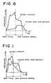
- the injection moldingis performed in a pattern of pressure change as shown in Fig. 6.
- the internal resin pressureis sufficiently low upon the filling, and the internal resin pressure higher than the pressure upon the filling is maintained upon the pressure holding.
- the internal resin pressure on the pressure holdingshould be increased to a level higher than that required for increasing a filling density of a molded article.
- the molten resinreaches the distal end of the cavity by means of the filling stage shown in Fig. 3.
- the filling rate or velocity of the molten resinis decreased.
- a thin layer of the resin in contact with the male and female dies 1 and 2is well cooled and solidified to form a thin hardened layer M1.
- the inside of the thin hardened layer M1is in a molten condition, and the holding pressure is applied to the entire resin through the interior molten layer M2.
- the thin hardened layer M1is formed, if the split surfaces 1a and 2a of the respective male and female dies 1 and 2 are moved away from each other to form between them a gap 3, the molten resin would not enter the gap 3, so that no flash would occur on the molded article.
- the resinis filled in the entire cavities at a relatively low internal resin pressure, it is possible to obtain molded articles with less possibility that internal stress is developed.
- the illustrated embodimenthas been described as being applied to such an injection molding construction and arrangement that the molded articles number twice that or those molded by the conventional molding method and the gate diameter is approximately 1.6 times that used in the conventional molding process
- the present inventionshould not be limited to this embodiment, but may be applied to any injection molding construction and arrangement, provided that as shown in Fig. 6 the molding is performed under the condition that internal resin pressure on filling is lower than the holding pressure. Accordingly, instead of the increase in the number of the molded articles, an extruded area of an article to be molded per se may be increased.
- the plungermay be decreased in feed rate, while the extruded area of the molded article per se is maintained as in the past.
- the filling speed or rate of the molten resinis decreased to allow the thin layer of the resin in contact with the die assembly to be formed into the thin hardened layer, so that should the dies be moved away from each other by the force exceeding the mold clamping capacity of the molding machine, no flash would be produced. Accordingly, as compared with the conventional molding method, should a molding machine having the same mold clamping capacity be utilized, it would be possible to mold an article having a greater extruded area. In addition, since the thin hardened layer is formed, no flash would be produced, should the molds be more or less inaccurate as to dimensions so that a gap initially exists between the split surfaces of the respective dies.
Landscapes
- Engineering & Computer Science (AREA)
- Manufacturing & Machinery (AREA)
- Mechanical Engineering (AREA)
- Injection Moulding Of Plastics Or The Like (AREA)
- Moulds For Moulding Plastics Or The Like (AREA)
Description
- The present invention relates to an injection molding process comprising the steps of:
clamping a male die and a female die together with a prescribed clamping force to provide at least one cavity of a prescribed extruded area therebetween;
subsequently injecting a molten resin at a prescribed injection pressure into said cavity to fill said cavity with said molten resin; and
subsequently holding said molten resin filled in said cavity at a prescribed holding pressure to solidify the resin within the cavity to produce a molded article. - A conventional process for injection molding is well known in the art. A plastic pellet is fed into a hopper of an injection molding machine such as an extruder. In the extruder, the plastic pellet is carried in a cylinder having a piston or a screw carrier and heated to produce a molten plastic. The molten plastic is extruded via a nozzle into a die assembly. The molten plastic is then maintained or held in the die assembly to provide a mold product. There are two types of pressures at the cylinder and the die assembly. A plunger pressure, i.e. an injection pressure, is created on the piston or screw in the cylinder while an internal resin pressure for molten plastic occurs in the die assembly.
- Fig. 1 shows a graph of the plunger pressure of the piston or screw of the conventional extruder vs. the internal resin pressure within a cavity defined in the die assembly when a molding is produced according to the conventional injection process. As shown in Fig. 1, the plunger pressure of the extruder is increased to a maximum ram pressure upon filling the molten resin into the die assembly. Upon holding and cooling the molten plastic the plunger pressure is decreased to the intermediate pressure and then to a minimum ram pressure. It should be noted that the internal resin pressure according to the conventional molding process has a synchronous pressure variation to that of the plunger pressure. The internal resin pressure is therefore increased upon filling the molten resin into the die assembly, substantially following a trace of the plunger pressure. The internal resin pressure then gradually decreases upon holding and cooling the molten resin in the die assembly since the molten resin is gradually cooled and solidified with a slight shrinkage of the resin. Such pressure change is considered to result from various factors such as, for example, the plunger pressure generated by a hydraulic pressure system, the volume or capacity of the cavity in the mold assembly, the flow resistance of molten resin against a passage from the nozzle to the cavity, a diameter of a gate facing to the cavity and the like. The most important factor to be considered is that a volume of the cavity to be extruded does not change upon filling and holding the molten plastic in the die assembly by the predetermined mold clamping force. A filling time is also effective to prevent the mold surface when cooled from flashing.
- An extruded area EA of the molten resin with an internal resin pressure IRP to a die assembly having a fixed mold clamping force MCF has an upper limit defined by:

- If the value of the EA x IRP, that is, the MCFmax exceeds the mold clamping force of the die assembly, as shown in Fig. 5, a space or
gap 3 appears betweensurfaces 1a and 2a of respective male and female dies 1 and 2 with an opening amounth. The molten resinM therefore enters thegap 3 to cause a flashMa to occur on a molded article. This would result in poor products and sometimes in interruption of the molding. On the other hand, in order to increase a filling density of the molded article to a value higher than a predetermined value, it is required to increase the internal resin pressure to a value higher than a predetermined value and, after all, the extruded area of the molten resin is limited by the mold clamping force of the die assembly. - An injection molding process as mentioned at the beginning is disclosed in German Offenlegungsschrift DE-OS 25 35 426. In this known injection molding process, after charging the mold, a dwell pressure of controlled variability is applied to the plastic material in the mold and the dwell pressure in a first stage is kept at a low value at which swelling of the mold is avoided and is raised to a higher value in a subsequent stage.
- It is therefore the object of the present invention to provide an increased output of an injection machine by using the process according to the present invention.
- This object is achieved by the features of the claim. As the extruded area is at least twice that of a conventional die assembly, the die assembly according to the invention can contain two cavities as compared with the one cavity of a conventional die assembly with the same clamping force.
- Because the internal resin pressure on the filling is low, the flow rate, i.e., filling velocity of the molten resin within the cavity is decreased and, accordingly, it takes a long time for the molten resin to reach the distal end of the cavity, so that during the movement a thin or shallow layer of the molten resin in contact with the die assembly is well cooled and solidified to form a thin hardened layer. The inside of the thin hardened layer is in a molten condition, and the holding pressure is applied through the interior molten resin to the entire solid resin. At this time, if the current force
 which exceeds the mold clamping force of the die assembly should be applied to the resin to move the male and female dies away from each other to define a gap between them, the molten resin would not enter the gap because of the presence of the thin hardened layer. Accordingly, no flash would occur on a molded product. Subsequently, the interior molten resin is also cooled and solidified.
- One way of carrying out the invention is described in detail below with reference to drawings which illustrate only one specific embodiment, in which:-
- Fig. 1 is a graph showing the characteristics of the conventional injection molding method;
- Fig. 2 is a cross-sectional view showing a die assembly and an injection molding machine, to which the present invention is applicable;
- Fig. 3 is a fragmentary enlarged cross-sectional view of a portion of a cavity encircled by (a) in Fig. 2, showing a condition of a filling stage;
- Fig. 4 is a view similar to Fig. 3, but showing a condition immediately after the filling;
- Fig. 5 is a view similar to Fig. 3, but showing a condition immediately after the filling in accordance with a conventional injection molding method; and
- Fig. 6 is a graph similar to Fig. 1, but showing the relationship between time and a plunger pressure and an internal resin pressure, in accordance with an embodiment of the present invention.
- An embodiment of the present invention will now be described with reference to Figs. 2 to 6 of the accompanying drawings. Fig. 2 is a cross-sectional view of a die assembly generally designated by the
reference 10, and an injection molding machine such as an extruder generally designated by thereference 50. - The die
assembly 10 is substantially identical in construction with a conventional one known to those skilled in the art, and will be described briefly. The dieassembly 10 comprises amale die 12 and afemale die 14 between which acavity 16 is provided to fill a molten resin. Thecavity 16, in this embodiment, is in the form of a shallow cup. Thefemale die 14 therefore is mounted on afixed bottom plate 18 through aspacer 20. Thebottom plate 18 is adjustable in position disposed on a base (not shown), while themale die 12 is mounted on amovable bottom plate 22 through aspacer 24. Themovable bottom plate 22 is also accessably disposed on the base. A pair ofejector plates die 12 andplate 22, with anejector pin 30 extending from theejector plates bottom plate 22. Themovable bottom plate 22 is slidably guided on the base such that theejector pin 30 causes the mold product to eject from the cavity. Thefixed bottom plate 18 has mounted thereon a locatingring 32 and amanifold 34 interfacing theextruder 50 to the dieassembly 10. Arunner bush 36 is mounted between thefemale die 14 and themanifold 34, and atorpedo spreader 38 extends into and through therunner bush 36. Thefemale die 14, therunner bush 36 and themanifold 34 have formed therein arunner 40 communicating with agate 42 which faces thecavity 16. In this embodiment, thedie assembly 10 has twocavities 16 each of which has a conventional cavity size with the characteristics shown in Fig. 6. In other words, the dieassembly 10 has an extruded area twice that of the conventional die assembly. Molten resin from theextruder 50 is simultaneously injected into each of thecavities 16. Thegate 42 facing eachcavity 16 has a diameter greater than 1.6 times, for example, that of a gate in the conventional die assembly. - The
extruder 50 is also substantially identical in construction with a conventional one known to those skilled in the art, and will be described briefly. Aplunger 52 which is reciprocally actuated by ahydraulic cylinder 54 is slidably received in aheating barrel 56 which is heated by aheater 58. Ahopper 60 is mounted on theheating barrel 56 adjacent to one end thereof, and anozzle 62 is provided at the other end or tip of theheating barrel 56. Alternatively, a screw rod for carrying the molten resin may be used. The screw rod is rotatably mounted within theheating barrel 56 so as to produce the plunger or ram pressure. An injection molding is performed by the above-describeddie assembly 10 and theextruder 50. In this case, if the plunger pressure, i.e., the pressure applied by theplunger 52 to the molten resin within theheating barrel 56 is the same as that in the conventional extruder, in other words, if the hydraulic pressure in thehydraulic cylinder 54 is the same as a conventional one, the injection molding is performed in a pattern of pressure change as shown in Fig. 6. Specifically, the internal resin pressure is sufficiently low upon the filling, and the internal resin pressure higher than the pressure upon the filling is maintained upon the pressure holding. The internal resin pressure on the pressure holding should be increased to a level higher than that required for increasing a filling density of a molded article. - When the molding is performed in such a pattern of pressure change, the molten resin reaches the distal end of the cavity by means of the filling stage shown in Fig. 3. However, as described above, because the internal resin pressure on the filling is low, the filling rate or velocity of the molten resin is decreased. As shown in Fig. 4, a thin layer of the resin in contact with the male and female dies 1 and 2 is well cooled and solidified to form a thin hardened layer M₁. The inside of the thin hardened layer M₁ is in a molten condition, and the holding pressure is applied to the entire resin through the interior molten layer M₂. In this manner, because the thin hardened layer M₁ is formed, if the split surfaces 1a and 2a of the respective male and female dies 1 and 2 are moved away from each other to form between them a
gap 3, the molten resin would not enter thegap 3, so that no flash would occur on the molded article. In addition, since the resin is filled in the entire cavities at a relatively low internal resin pressure, it is possible to obtain molded articles with less possibility that internal stress is developed. - Although the illustrated embodiment has been described as being applied to such an injection molding construction and arrangement that the molded articles number twice that or those molded by the conventional molding method and the gate diameter is approximately 1.6 times that used in the conventional molding process, the present invention should not be limited to this embodiment, but may be applied to any injection molding construction and arrangement, provided that as shown in Fig. 6 the molding is performed under the condition that internal resin pressure on filling is lower than the holding pressure. Accordingly, instead of the increase in the number of the molded articles, an extruded area of an article to be molded per se may be increased. In addition, the plunger may be decreased in feed rate, while the extruded area of the molded article per se is maintained as in the past.
- As described above, in accordance with the present invention, since the injection is performed in such a condition that the internal resin pressure on the filling is lower than the internal resin pressure on the pressure holding, the filling speed or rate of the molten resin is decreased to allow the thin layer of the resin in contact with the die assembly to be formed into the thin hardened layer, so that should the dies be moved away from each other by the force exceeding the mold clamping capacity of the molding machine, no flash would be produced. Accordingly, as compared with the conventional molding method, should a molding machine having the same mold clamping capacity be utilized, it would be possible to mold an article having a greater extruded area. In addition, since the thin hardened layer is formed, no flash would be produced, should the molds be more or less inaccurate as to dimensions so that a gap initially exists between the split surfaces of the respective dies.


Claims (1)
- An injection molding process comprising the steps of:(a) clamping a male die (12) and a female die (14) together with a prescribed clamping force (MCF) to provide at least one cavity (16) of a prescribed extruded area (EA) therebetween;(b) subsequently injecting a molten resin (M) at a prescribed injection pressure into said cavity (16) to fill said cavity (16) with said molten resin (M); and(c) subsequently holding said molten resin (M) filled in said cavity (16) at a prescribed holding pressure to solidify the resin (M) within the cavity (16) to produce a molded article;characterized in that:(d) during said filling step (b) the injection pressure is controlled so as to increase an internal resin pressure (IRP) gradually whilst moving said molten resin (M) within said cavity (16) at such a speed that the portion of said molten resin (M) in contact with the surfaces of said cavity (16) is solidified to form during the filling step a thin hardened layer (M₁) on the cavity surfaces, which layer is hard enough to prevent penetration of molten resin into a gap between the dies (12, 14); and(e) said pressure holding step (c) is effected so as to continue increasing the internal resin pressure (IRP) to a maximum at the beginning of said pressure holding step (c) and to maintain said maximum level substantially throughout said pressure holding step (c), whereby the force defined by the extruded area (EA), which is at least twice that of a conventional die assembly with the same clamping force, multiplied by the internal resin pressure (IRP) exceeds said clamping force (MCF) during the pressure holding step (c).
Applications Claiming Priority (2)
| Application Number | Priority Date | Filing Date | Title |
|---|---|---|---|
| JP59170705AJPH0684031B2 (en) | 1984-08-16 | 1984-08-16 | Injection molding method |
| JP170705/84 | 1984-08-16 |
Publications (3)
| Publication Number | Publication Date |
|---|---|
| EP0172536A2 EP0172536A2 (en) | 1986-02-26 |
| EP0172536A3 EP0172536A3 (en) | 1988-03-09 |
| EP0172536B1true EP0172536B1 (en) | 1992-06-03 |
Family
ID=15909864
Family Applications (1)
| Application Number | Title | Priority Date | Filing Date |
|---|---|---|---|
| EP85110263AExpired - LifetimeEP0172536B1 (en) | 1984-08-16 | 1985-08-16 | Injection molding process for molten plastic |
Country Status (7)
| Country | Link |
|---|---|
| US (2) | US4882117A (en) |
| EP (1) | EP0172536B1 (en) |
| JP (1) | JPH0684031B2 (en) |
| KR (1) | KR900007345B1 (en) |
| DE (1) | DE3586151T2 (en) |
| HK (1) | HK87993A (en) |
| ZA (1) | ZA856233B (en) |
Families Citing this family (14)
| Publication number | Priority date | Publication date | Assignee | Title |
|---|---|---|---|---|
| JPS62204451A (en)* | 1986-03-03 | 1987-09-09 | Daicel Chem Ind Ltd | Plastic substrate for optical disk and its production |
| JPH0733044B2 (en)* | 1986-11-12 | 1995-04-12 | 三菱マテリアル株式会社 | Injection molding method |
| JPH0741648B2 (en)* | 1990-12-28 | 1995-05-10 | 日プラ株式会社 | In-mold labeling container with thread bottom and manufacturing method thereof |
| JPH0664016A (en)* | 1992-08-24 | 1994-03-08 | Matsushita Electric Ind Co Ltd | Resin molding condition control device and control method |
| EP0642910A1 (en)* | 1992-12-27 | 1995-03-15 | Nissha Printing Co., Ltd. | Insert molded article, and apparatus and method for producing the insert molded article |
| JP3512595B2 (en)* | 1996-11-07 | 2004-03-29 | 株式会社リコー | Molding method of plastic molded article and mold for molding plastic molded article |
| JPH07256722A (en)* | 1994-03-24 | 1995-10-09 | Fanuc Ltd | Injection molding control method in injection molding machine |
| US5766526B1 (en)* | 1994-04-20 | 1999-08-24 | Fuji Photo Film Co Ltd | Method and apparatus for injection molding |
| JP3385491B2 (en)* | 1994-06-21 | 2003-03-10 | コニカ株式会社 | Injection molding method |
| JP3246434B2 (en) | 1998-02-13 | 2002-01-15 | 三菱マテリアル株式会社 | Injection molding method, injection mold and valve gate device |
| JP3225914B2 (en)* | 1998-02-13 | 2001-11-05 | 三菱マテリアル株式会社 | Valve gate device and injection mold provided with this valve gate device |
| US20060082010A1 (en)* | 2004-10-19 | 2006-04-20 | Saggese Stefano M | Intelligent molding environment and method of controlling applied clamp tonnage |
| CN101863104A (en)* | 2010-05-26 | 2010-10-20 | 大连理工大学 | Injection molding process of plastic microfluidic chip |
| CN102574319B (en)* | 2010-06-25 | 2014-09-10 | 日精树脂工业株式会社 | Molding method of injection molding machine |
Family Cites Families (22)
| Publication number | Priority date | Publication date | Assignee | Title |
|---|---|---|---|---|
| US2685708A (en)* | 1951-01-29 | 1954-08-10 | Aircraft Marine Prod Inc | Molding method |
| FR1116870A (en)* | 1955-04-27 | 1956-05-14 | Low pressure injection molding process, in particular for the manufacture of laminated parts | |
| DE1779504B2 (en)* | 1968-08-21 | 1972-05-31 | Eckert & Ziegler Gmbh, 8832 Weissenburg | METHOD FOR PROCESSING HEAT-RESISTANT PLASTICS, IN PARTICULAR THERMAL PLASTICS FROM THE AMINOPLASTIC FAMILY ON INJECTION MOLDING MACHINES |
| DE2300171A1 (en)* | 1973-01-03 | 1974-07-11 | Bucher Guyer Ag Masch | PROCESS FOR REGULATING THE CURING TIME OF THE PLASTIC COMPOUND IN THE FORM OF INJECTION MOLDING MACHINE |
| JPS5729257B2 (en)* | 1973-11-21 | 1982-06-22 | ||
| DE2532429C3 (en)* | 1975-07-19 | 1981-12-17 | G. Bauknecht Gmbh, 7000 Stuttgart | Method and device for injection molding a plastic compound with variable injection speed |
| DE2535426A1 (en)* | 1975-08-08 | 1977-02-24 | Demag Kunststofftech | Pressure controlled injection moulder for highly accurate prods. - holds post injection load temporarily below that causing breathing |
| US4325896A (en)* | 1975-10-08 | 1982-04-20 | Solid Controls, Inc. | Electro-hydraulic ram control apparatus |
| DE2612176A1 (en)* | 1976-03-23 | 1977-10-06 | Ver Foerderung Inst Kunststoff | Injection moulding thermosetting and elastomeric materials - preventing spew fin formation by delaying sec. press. until viscosity has increased |
| US4313901A (en)* | 1976-06-10 | 1982-02-02 | Resistoflex Corporation | Isothermal transfer molding |
| DE2723071A1 (en)* | 1977-05-21 | 1978-11-30 | Linde Ag | INJECTION MOLDING |
| US4131596A (en)* | 1977-08-22 | 1978-12-26 | Logic Devices, Inc. | Sensing system and method for plastic injection molding |
| US4237089A (en)* | 1978-07-19 | 1980-12-02 | Sunds Ab | Method of reducing internal stresses and improving the mechanical properties of injection molded thermoplastic resins |
| AU506115B1 (en)* | 1978-11-22 | 1979-12-13 | Owens-Illinois, Inc | Multistep molding of plastic articles |
| US4309379A (en)* | 1978-12-21 | 1982-01-05 | Hooker Chemicals & Plastics Corp. | Method and apparatus for runnerless injection-compression molding thermosetting materials |
| JPS55142632A (en)* | 1979-03-31 | 1980-11-07 | Toyota Motor Corp | Low-pressure injecting method using screw inlying injection molding machine |
| CH642905A5 (en)* | 1979-07-16 | 1984-05-15 | Netstal Ag Maschf Giesserei | INJECTION MOLDING MACHINE. |
| JPS5774135A (en)* | 1980-10-29 | 1982-05-10 | Toshiba Mach Co Ltd | High pressure injection molding method and device therefor |
| JPS59165634A (en)* | 1983-03-11 | 1984-09-18 | Mitsubishi Heavy Ind Ltd | Injection molding method |
| JPS5964336A (en)* | 1983-07-08 | 1984-04-12 | Toshiba Mach Co Ltd | Method and apparatus for controlling injection process of injection molding machine |
| US4609516A (en)* | 1984-02-17 | 1986-09-02 | Continental Pet Technologies, Inc. | Method of forming laminated preforms |
| US5093740A (en)* | 1991-02-28 | 1992-03-03 | Raytheon Company | Optical beam steerer having subaperture addressing |
- 1984
- 1984-08-16JPJP59170705Apatent/JPH0684031B2/ennot_activeExpired - Lifetime
- 1985
- 1985-06-14KRKR1019850004207Apatent/KR900007345B1/ennot_activeExpired
- 1985-08-16DEDE8585110263Tpatent/DE3586151T2/ennot_activeExpired - Lifetime
- 1985-08-16EPEP85110263Apatent/EP0172536B1/ennot_activeExpired - Lifetime
- 1985-08-16ZAZA856233Apatent/ZA856233B/enunknown
- 1988
- 1988-06-28USUS07/212,149patent/US4882117A/ennot_activeExpired - Lifetime
- 1988-08-17USUS07/233,904patent/US4826641A/ennot_activeExpired - Lifetime
- 1993
- 1993-08-26HKHK879/93Apatent/HK87993A/ennot_activeIP Right Cessation
Also Published As
| Publication number | Publication date |
|---|---|
| EP0172536A3 (en) | 1988-03-09 |
| HK87993A (en) | 1993-09-03 |
| KR860001702A (en) | 1986-03-22 |
| DE3586151T2 (en) | 1992-12-03 |
| JPH0684031B2 (en) | 1994-10-26 |
| JPS6149820A (en) | 1986-03-11 |
| EP0172536A2 (en) | 1986-02-26 |
| US4882117A (en) | 1989-11-21 |
| DE3586151D1 (en) | 1992-07-09 |
| KR900007345B1 (en) | 1990-10-08 |
| ZA856233B (en) | 1986-04-30 |
| US4826641A (en) | 1989-05-02 |
Similar Documents
| Publication | Publication Date | Title |
|---|---|---|
| EP0172536B1 (en) | Injection molding process for molten plastic | |
| US3737272A (en) | Improved injection mold apparatus for the production of substantially cup-shaped and sleeve-shaped thermoplastic containers | |
| EP0640460B1 (en) | Method for producing a thin film | |
| US2828507A (en) | Injection molding press having valved gate | |
| US4980115A (en) | Method for making an injection-molded product having a partly thin portion | |
| EP0100603A1 (en) | Stabilised core injection molding | |
| US5968439A (en) | Method for simultaneous injection and compression | |
| US5922266A (en) | Injection molding | |
| US5948327A (en) | Lens injection-compression-molding method | |
| US4342717A (en) | Injection moulding method and apparatus with mould runner reservoir and shot extension | |
| US4256689A (en) | Injection moulding method and apparatus with mould runner reservoir and shot extension | |
| US3969461A (en) | Transfer molding thermosetting polymeric material | |
| JP3185197B2 (en) | Injection molding method | |
| US4370123A (en) | Apparatus for runnerless injection compression molding of thermosetting materials | |
| MXPA03000142A (en) | Method and apparatus for injection molding. | |
| US3374502A (en) | Sprue bushing and nozzle assembly | |
| US3911075A (en) | Transfer molding thermosetting polymeric material | |
| JPH0768601A (en) | Runnerless mold | |
| JP3357141B2 (en) | Resin molding equipment | |
| JP2678933B2 (en) | Injection molding equipment | |
| US5480606A (en) | Method and apparatus for reverse gated compression molding of thermoplastic material | |
| JP2736664B2 (en) | Manufacturing method of injection molded products | |
| USRE28158E (en) | Displacement molding plastic articles | |
| US3954362A (en) | Transfer molding thermosetting polymeric material | |
| US3632281A (en) | Plastic-molding machine |
Legal Events
| Date | Code | Title | Description |
|---|---|---|---|
| PUAI | Public reference made under article 153(3) epc to a published international application that has entered the european phase | Free format text:ORIGINAL CODE: 0009012 | |
| AK | Designated contracting states | Designated state(s):DE FR GB | |
| 17P | Request for examination filed | Effective date:19861103 | |
| PUAL | Search report despatched | Free format text:ORIGINAL CODE: 0009013 | |
| AK | Designated contracting states | Kind code of ref document:A3 Designated state(s):DE FR GB | |
| 17Q | First examination report despatched | Effective date:19890518 | |
| RAP1 | Party data changed (applicant data changed or rights of an application transferred) | Owner name:MITSUBISHI MATERIALS CORPORATION | |
| GRAA | (expected) grant | Free format text:ORIGINAL CODE: 0009210 | |
| AK | Designated contracting states | Kind code of ref document:B1 Designated state(s):DE FR GB | |
| ET | Fr: translation filed | ||
| REF | Corresponds to: | Ref document number:3586151 Country of ref document:DE Date of ref document:19920709 | |
| PLBE | No opposition filed within time limit | Free format text:ORIGINAL CODE: 0009261 | |
| STAA | Information on the status of an ep patent application or granted ep patent | Free format text:STATUS: NO OPPOSITION FILED WITHIN TIME LIMIT | |
| 26N | No opposition filed | ||
| REG | Reference to a national code | Ref country code:GB Ref legal event code:IF02 | |
| PGFP | Annual fee paid to national office [announced via postgrant information from national office to epo] | Ref country code:GB Payment date:20040730 Year of fee payment:20 | |
| PGFP | Annual fee paid to national office [announced via postgrant information from national office to epo] | Ref country code:DE Payment date:20040805 Year of fee payment:20 | |
| PGFP | Annual fee paid to national office [announced via postgrant information from national office to epo] | Ref country code:FR Payment date:20040809 Year of fee payment:20 | |
| PG25 | Lapsed in a contracting state [announced via postgrant information from national office to epo] | Ref country code:GB Free format text:LAPSE BECAUSE OF EXPIRATION OF PROTECTION Effective date:20050815 | |
| REG | Reference to a national code | Ref country code:GB Ref legal event code:PE20 |