EP0170895B1 - Improved electrodeionization apparatus and method - Google Patents
Improved electrodeionization apparatus and methodDownload PDFInfo
- Publication number
- EP0170895B1 EP0170895B1EP85108378AEP85108378AEP0170895B1EP 0170895 B1EP0170895 B1EP 0170895B1EP 85108378 AEP85108378 AEP 85108378AEP 85108378 AEP85108378 AEP 85108378AEP 0170895 B1EP0170895 B1EP 0170895B1
- Authority
- EP
- European Patent Office
- Prior art keywords
- liquid
- compartments
- ion
- depletion
- stage
- Prior art date
- Legal status (The legal status is an assumption and is not a legal conclusion. Google has not performed a legal analysis and makes no representation as to the accuracy of the status listed.)
- Expired
Links
- 238000009296electrodeionizationMethods0.000titleclaimsdescription39
- 238000000034methodMethods0.000titleclaimsdescription36
- 239000007788liquidSubstances0.000claimsdescription96
- 150000002500ionsChemical class0.000claimsdescription49
- 239000012528membraneSubstances0.000claimsdescription37
- 125000006850spacer groupChemical group0.000claimsdescription37
- 239000011324beadSubstances0.000claimsdescription20
- XLYOFNOQVPJJNP-UHFFFAOYSA-NwaterSubstancesOXLYOFNOQVPJJNP-UHFFFAOYSA-N0.000claimsdescription17
- 238000005342ion exchangeMethods0.000claimsdescription15
- NWUYHJFMYQTDRP-UHFFFAOYSA-N1,2-bis(ethenyl)benzene;1-ethenyl-2-ethylbenzene;styreneChemical compoundC=CC1=CC=CC=C1.CCC1=CC=CC=C1C=C.C=CC1=CC=CC=C1C=CNWUYHJFMYQTDRP-UHFFFAOYSA-N0.000claimsdescription13
- 150000001450anionsChemical class0.000claimsdescription11
- 150000001768cationsChemical class0.000claimsdescription11
- 239000003792electrolyteSubstances0.000claimsdescription11
- 239000003456ion exchange resinSubstances0.000claimsdescription10
- 229920003303ion-exchange polymerPolymers0.000claimsdescription10
- 239000003957anion exchange resinSubstances0.000claimsdescription7
- 230000000694effectsEffects0.000claimsdescription7
- 239000000203mixtureSubstances0.000claimsdescription7
- 239000003729cation exchange resinSubstances0.000claimsdescription6
- 230000000717retained effectEffects0.000claimsdescription5
- 238000012546transferMethods0.000claimsdescription3
- 239000008247solid mixtureSubstances0.000claims2
- 229920002536Scavenger resinPolymers0.000claims1
- GPRLSGONYQIRFK-UHFFFAOYSA-NhydronChemical compound[H+]GPRLSGONYQIRFK-UHFFFAOYSA-N0.000claims1
- 230000000779depleting effectEffects0.000description27
- 239000000463materialSubstances0.000description20
- 239000000047productSubstances0.000description9
- 125000000129anionic groupChemical class0.000description5
- 125000002091cationic groupChemical class0.000description5
- 239000011347resinSubstances0.000description5
- 229920005989resinPolymers0.000description5
- CHRJZRDFSQHIFI-UHFFFAOYSA-N1,2-bis(ethenyl)benzene;styreneChemical compoundC=CC1=CC=CC=C1.C=CC1=CC=CC=C1C=CCHRJZRDFSQHIFI-UHFFFAOYSA-N0.000description4
- FAPWRFPIFSIZLT-UHFFFAOYSA-MSodium chlorideChemical compound[Na+].[Cl-]FAPWRFPIFSIZLT-UHFFFAOYSA-M0.000description4
- 238000000909electrodialysisMethods0.000description4
- 239000012530fluidSubstances0.000description4
- 239000002245particleSubstances0.000description4
- 239000003643water by typeSubstances0.000description4
- LSNNMFCWUKXFEE-UHFFFAOYSA-MBisulfiteChemical groupOS([O-])=OLSNNMFCWUKXFEE-UHFFFAOYSA-M0.000description3
- 238000010276constructionMethods0.000description3
- 238000013461designMethods0.000description3
- 125000000524functional groupChemical group0.000description3
- -1hydroxyl ionsChemical class0.000description3
- 230000010287polarizationEffects0.000description3
- 125000001453quaternary ammonium groupChemical group0.000description3
- 150000003839saltsChemical class0.000description3
- 239000011780sodium chlorideSubstances0.000description3
- VYPSYNLAJGMNEJ-UHFFFAOYSA-NSilicium dioxideChemical compoundO=[Si]=OVYPSYNLAJGMNEJ-UHFFFAOYSA-N0.000description2
- 238000011001backwashingMethods0.000description2
- 238000010586diagramMethods0.000description2
- 239000000835fiberSubstances0.000description2
- 229910052739hydrogenInorganic materials0.000description2
- 239000001257hydrogenSubstances0.000description2
- 238000004519manufacturing processMethods0.000description2
- 239000002516radical scavengerSubstances0.000description2
- 230000000452restraining effectEffects0.000description2
- 238000000926separation methodMethods0.000description2
- 239000007787solidSubstances0.000description2
- 239000012498ultrapure waterSubstances0.000description2
- 238000011144upstream manufacturingMethods0.000description2
- 239000002699waste materialSubstances0.000description2
- QJZYHAIUNVAGQP-UHFFFAOYSA-N3-nitrobicyclo[2.2.1]hept-5-ene-2,3-dicarboxylic acidChemical compoundC1C2C=CC1C(C(=O)O)C2(C(O)=O)[N+]([O-])=OQJZYHAIUNVAGQP-UHFFFAOYSA-N0.000description1
- 229920003934Aciplex®Polymers0.000description1
- UFHFLCQGNIYNRP-UHFFFAOYSA-NHydrogenChemical compound[H][H]UFHFLCQGNIYNRP-UHFFFAOYSA-N0.000description1
- 239000002033PVDF binderSubstances0.000description1
- 239000004698PolyethyleneSubstances0.000description1
- 238000005349anion exchangeMethods0.000description1
- 239000012267brineSubstances0.000description1
- 238000005341cation exchangeMethods0.000description1
- 230000005465channelingEffects0.000description1
- 238000004140cleaningMethods0.000description1
- 238000004891communicationMethods0.000description1
- 238000005056compactionMethods0.000description1
- 230000002860competitive effectEffects0.000description1
- 239000000356contaminantSubstances0.000description1
- 239000008367deionised waterSubstances0.000description1
- 229910021641deionized waterInorganic materials0.000description1
- 238000005115demineralizationMethods0.000description1
- 230000002328demineralizing effectEffects0.000description1
- 238000010612desalination reactionMethods0.000description1
- 238000005516engineering processMethods0.000description1
- 239000000945fillerSubstances0.000description1
- 239000002509fulvic acidSubstances0.000description1
- 239000004021humic acidSubstances0.000description1
- 239000003014ion exchange membraneSubstances0.000description1
- 229920005610ligninPolymers0.000description1
- 238000004811liquid chromatographyMethods0.000description1
- 239000011244liquid electrolyteSubstances0.000description1
- 239000012263liquid productSubstances0.000description1
- 238000012423maintenanceMethods0.000description1
- 238000005374membrane filtrationMethods0.000description1
- BVWUEIUNONATML-UHFFFAOYSA-Nn-benzylethenamineChemical compoundC=CNCC1=CC=CC=C1BVWUEIUNONATML-UHFFFAOYSA-N0.000description1
- 229920000573polyethylenePolymers0.000description1
- 238000000746purificationMethods0.000description1
- 238000011160researchMethods0.000description1
- 238000007789sealingMethods0.000description1
- 239000000377silicon dioxideSubstances0.000description1
- MKWYFZFMAMBPQK-UHFFFAOYSA-Jsodium feredetateChemical compound[Na+].[Fe+3].[O-]C(=O)CN(CC([O-])=O)CCN(CC([O-])=O)CC([O-])=OMKWYFZFMAMBPQK-UHFFFAOYSA-J0.000description1
- HPALAKNZSZLMCH-UHFFFAOYSA-Msodium;chloride;hydrateChemical compoundO.[Na+].[Cl-]HPALAKNZSZLMCH-UHFFFAOYSA-M0.000description1
- 239000000126substanceSubstances0.000description1
- 229920001864tanninPolymers0.000description1
- 239000001648tanninSubstances0.000description1
- 235000018553tanninNutrition0.000description1
Images


Classifications
- C—CHEMISTRY; METALLURGY
- C02—TREATMENT OF WATER, WASTE WATER, SEWAGE, OR SLUDGE
- C02F—TREATMENT OF WATER, WASTE WATER, SEWAGE, OR SLUDGE
- C02F1/00—Treatment of water, waste water, or sewage
- C02F1/46—Treatment of water, waste water, or sewage by electrochemical methods
- C02F1/469—Treatment of water, waste water, or sewage by electrochemical methods by electrochemical separation, e.g. by electro-osmosis, electrodialysis, electrophoresis
- C02F1/4693—Treatment of water, waste water, or sewage by electrochemical methods by electrochemical separation, e.g. by electro-osmosis, electrodialysis, electrophoresis electrodialysis
- C02F1/4695—Treatment of water, waste water, or sewage by electrochemical methods by electrochemical separation, e.g. by electro-osmosis, electrodialysis, electrophoresis electrodialysis electrodeionisation
- B—PERFORMING OPERATIONS; TRANSPORTING
- B01—PHYSICAL OR CHEMICAL PROCESSES OR APPARATUS IN GENERAL
- B01D—SEPARATION
- B01D61/00—Processes of separation using semi-permeable membranes, e.g. dialysis, osmosis or ultrafiltration; Apparatus, accessories or auxiliary operations specially adapted therefor
- B01D61/42—Electrodialysis; Electro-osmosis ; Electro-ultrafiltration; Membrane capacitive deionization
- B01D61/44—Ion-selective electrodialysis
- B01D61/46—Apparatus therefor
- B01D61/48—Apparatus therefor having one or more compartments filled with ion-exchange material, e.g. electrodeionisation
- B—PERFORMING OPERATIONS; TRANSPORTING
- B01—PHYSICAL OR CHEMICAL PROCESSES OR APPARATUS IN GENERAL
- B01J—CHEMICAL OR PHYSICAL PROCESSES, e.g. CATALYSIS OR COLLOID CHEMISTRY; THEIR RELEVANT APPARATUS
- B01J47/00—Ion-exchange processes in general; Apparatus therefor
- B01J47/02—Column or bed processes
- B01J47/06—Column or bed processes during which the ion-exchange material is subjected to a physical treatment, e.g. heat, electric current, irradiation or vibration
- B01J47/08—Column or bed processes during which the ion-exchange material is subjected to a physical treatment, e.g. heat, electric current, irradiation or vibration subjected to a direct electric current
- C—CHEMISTRY; METALLURGY
- C02—TREATMENT OF WATER, WASTE WATER, SEWAGE, OR SLUDGE
- C02F—TREATMENT OF WATER, WASTE WATER, SEWAGE, OR SLUDGE
- C02F1/00—Treatment of water, waste water, or sewage
- C02F1/42—Treatment of water, waste water, or sewage by ion-exchange
- C—CHEMISTRY; METALLURGY
- C02—TREATMENT OF WATER, WASTE WATER, SEWAGE, OR SLUDGE
- C02F—TREATMENT OF WATER, WASTE WATER, SEWAGE, OR SLUDGE
- C02F1/00—Treatment of water, waste water, or sewage
- C02F1/46—Treatment of water, waste water, or sewage by electrochemical methods
- C02F1/4604—Treatment of water, waste water, or sewage by electrochemical methods for desalination of seawater or brackish water
- C—CHEMISTRY; METALLURGY
- C02—TREATMENT OF WATER, WASTE WATER, SEWAGE, OR SLUDGE
- C02F—TREATMENT OF WATER, WASTE WATER, SEWAGE, OR SLUDGE
- C02F2201/00—Apparatus for treatment of water, waste water or sewage
- C02F2201/46—Apparatus for electrochemical processes
- C02F2201/461—Electrolysis apparatus
- C02F2201/46105—Details relating to the electrolytic devices
- C02F2201/46115—Electrolytic cell with membranes or diaphragms
- C—CHEMISTRY; METALLURGY
- C02—TREATMENT OF WATER, WASTE WATER, SEWAGE, OR SLUDGE
- C02F—TREATMENT OF WATER, WASTE WATER, SEWAGE, OR SLUDGE
- C02F2201/00—Apparatus for treatment of water, waste water or sewage
- C02F2201/46—Apparatus for electrochemical processes
- C02F2201/461—Electrolysis apparatus
- C02F2201/46105—Details relating to the electrolytic devices
- C02F2201/4612—Controlling or monitoring
- C02F2201/46125—Electrical variables
- C02F2201/4613—Inversing polarity
- C—CHEMISTRY; METALLURGY
- C02—TREATMENT OF WATER, WASTE WATER, SEWAGE, OR SLUDGE
- C02F—TREATMENT OF WATER, WASTE WATER, SEWAGE, OR SLUDGE
- C02F2209/00—Controlling or monitoring parameters in water treatment
- C02F2209/05—Conductivity or salinity
Definitions
- This inventionrelates to a novel electrodeionization apparatus and method adapted to transfer ions in a liquid under the influence of a polar field. More specifically, this invention relates to an electrodeionization apparatus and method adapted to purify aqueous liquids to effect the production of high purity water.
- the first apparatus and method for treating liquids by electrodeionizationwas described by Kollsman in U.S. Patent Nos. 2,689,826 and 2,815,320.
- the first of these patentsdescribes an apparatus and process for the removal of ions within a liquid mixture in a depleting chamber through a series of anionic and cationic diaphragms into a second volume of liquid in a concentration chamber under the influence of an electrical potential which causes the preselected ions to travel in a predetermined direction.
- the volume of the liquid being treatedis depleted of ions while the volume of the second liquid becomes enriched with the transferred ions and carries them in concentrated form.
- the second of these patentsdescribes the use of macroporous beads formed of ion exchange resins as a filler material positioned between the anionic or cationic diaphragms.
- This ion exchange resinacts as a path for ion transfer and also serves as an increased conductivity bridge between the membranes for the movement of ions.
- These patentsrepresent the primary structural framework and theory of electrodeionization as a technique.
- electrodeionizationrefers to the process wherein an ion exchange material is positioned between the anionic and cationic diaphragms.
- electrodialysisrelates to such a process which does not utilize ion exchange resins between the anionic and cationic diaphragms.
- the present inventionprovides a method and apparatus capable of continuously producing water of up to about 10 mega-ohm cm quality or higher over long periods of time while avoiding serious reduction of ion exchange resin performance and avoiding the build-up of particulates and scale within the electrodeionization apparatus.
- the apparatusincludes a plurality of electrodeionization compartments whose thickness, width and configuration are controlled and which contain ion exchange materials such as beads, fibers or the like.
- the electrodeionization ion depleting compartments wherein liquid is depleted of ionsare formed from a spacer having a hollow central portion divided by ribs to define subcompartments.
- the ion exchange resin beads within the subcompartmentsare retained in the subcompartments by bonding or physically restraining a cationic permeable membrane to one surface of the depleting compartments and to the ribs and bonding or physically restraining an anionic permeable membrane to the opposing surface of the depleting compartment to the ribs, thereby to define the subcompartments.
- the concentration compartments into which ions migrate from the depleting compartmentsare free of ion exchange beads.
- the electrodeionization apparatuscan comprise a single stage or a-plurality of stages in series wherein the process voltage can be controlled independently in each stage, if desired.
- the inventionrelates to an electrodeionizition apparatus according to claim 1.
- the inventionfurther relates to a process for removing ions from a liquid by means of said apparatus.
- each electrodeionization electrical stageincludes an anode and a cathode, and their compartments, series of concentration compartments which include means for causing turbulent flow of liquid passing therethrough and a series of depletion compartments that contain an ion exchange material such as a mixture of anion exchange resin and cation exchange resin.
- the depletion compartmentsare formed so that the ion exchange resin mixture is housed within independent discrete subcompartments each of which has a width of preferably between 1.27 and 3.81 cm (0.5 and 1.5 inches).
- the discrete subcompartmentsare formed by securing, such as by bonding, both the anion permeable membrane and the cation permeable membrane to the periphery of the depletion compartment and to ribs which extend across the thickness of and along the entire length of the depletion compartment so that each subcompartment is defined by a pair of ribs, the anion permeable exchange membrane and the cation permeable membrane. It has been found, in accordance with this invention that the thickness and width of the depletion compartments are critical to achieving efficient operation of the electrodeionization apparatus.
- the solid ion exchange material positioned within the subcompartmentsare constrained from moving between subcompartments by the ribs and ion permeable membranes.
- suitable solid ion exchange materialsinclude fibers or beads or the like.
- typical bead diameteris 2.54 x 0.4 cm (0.4 inches) or less, preferably between 2.54 x .033 and 2.54 x .012 cm (.033 and .012 inches) in diameter [.510 to .207 mm (20 to 50 mesh)].
- the electrodeionization apparatuscan comprise one or a plurality of stages.
- an anodeis positioned at an opposite end of a stack of depleting and concentrating compartments from an end at which a cathode is positioned.
- Each anode and cathodeis provided with an adjacent electrode spacer and an ion permeable membrane wherein an electrolyte passes through the electrode spacer.
- the remaining portion of each stagecomprises a series of alternating depletion and concentrating compartments constructed as set forth herein.
- the liquid to be depleted of ionscan be passed in parallel through each depleting compartment in each stage and a second liquid can be passed through each concentrating compartment in parallel in each stage in order to effect removal of ions from the first liquid in the depleting compartments into the second liquid in the concentrating compartments.
- the liquid removed from the depleting compartments in an upstream stagecan be directed in series into the depleting compartments in the next adjacent downstream stage.
- the liquid removed from the concentrating compartments of an upstream stagecan be directed in series to the concentrating compartments in the next adjacent downstream stage.
- Electrolytecan be passed through the spacer adjacent each electrode in the electrodeionization apparatus and is removed from the electrodeionization apparatus. Other possible liquid flow arrangements will be discussed in detail with reference to Figures 10 and 11.
- the thickness of the subcompartmentmust be between 0.127 and 0.635 cm (0.25 and 0.05 inches), preferably between 2.54 x .06 and 2.54 x .125 cm (.06 and .125 inches).
- the width of the subcompartmentmust be between 0.762 and 10.16 cm (0.3 and 4 inches), preferably between 2.54 x .5 and 2.54 x 1.5 cm (.5 and 1.5 inches).
- the longer the subcompartment lengththe greater the ion removal from the liquid therein.
- the length of the subcompartmentsare between 2.54 x 5 and 2.54 x 70 cm (5 inches and 70 inches).
- the subcompartmentscan contain 100% anion exchange material, 100% cation exchange material or a mixture of the two. When it is desired to remove only a particular anion or particular cation, 100% of the appropriate ion exchange material is used. Usually it is desired to remove both cations and anions in order to produce a purified liquid product. When utilizing strong acid-base resin materials such as beads, the ratio of anion exchange resin beads to cation exchange resin beads generally are about 60 to 40 by volume.
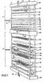
- FIG. 1A multistage electrodeionization apparatus is shown in Figure 1.
- the electrodeionization apparatus 10comprises a first stage 12 and a second stage 14.
- the first stage 12includes an end plate 13 having an expandable bladder 15 and an inlet 16 for fluid to expand the bladder 15.
- Adjacent the endplate 13is an endblock 17 to house electrode 9 and provide desired manifolding.
- An electrode spacer 18is positioned adjacent to the end block 17 and includes a screen 19 which effects turbulent flow of liquid passing through the electrode spacer 18.
- An ion permeable membrane 20is sealed to the periphery 21 of electrode spacer 18.
- a spacer 22 formed of flexible materialincludes a screen 24. The spacer 22 and screen 24 comprise the concentrating compartment of the electrodeionization apparatus of this invention.
- the depleting compartment structure of this inventioncomprises an ion permeable membrane 26, a spacer formed of rigid material 28 and an ion permeable membrane 30.
- the ion permeable membranes 26 and 30are sealed to the periphery 32 of the spacer 28 on opposite surfaces of the spacer 28.
- Mixed ion exchange resin beads 34are housed within a central space which includes ribs (not shown) and are retained therein by the membranes 26 and 30.
- the unit which comprises spacers 22 and 28 and membranes 26 and 30are repeated usually between about 5 and about 100 times in order to provide reasonable liquid flow through capacity in stage 12.
- a spacer 38 formed of flexible material and ion exchange membrane 40 sealed to the periphery of spacer 38forms the end concentrating compartment.
- An electrode spacer 42is positioned adjacent the middle block 44 and end electrode 46.
- Stage 14is identical in structure to stage 12 but can have more or fewer cell pairs and includes electrode spacer 48 and membrane 50 attached to the periphery of electrode spacer 48.
- An electrode 52is provided in middle block 44.
- the repeating unit in stage 14comprises a spacer 54 formed of flexible material as well as a spacer 56 formed of rigid material to which are secured such as by bonding or by mechanical means membranes 58 and 60.
- a spacer 61 formed of flexible materialthen is provided followed by a membrane 63, an electrode spacer 65, and endblock 66 and electrode 67, an end plate 68 and a flexible bladder 70 which is inflated by means of fluid passing through conduit 72. Flowthrough of liquid in the concentrating and depleting compartments as well as in the electrode compartment will be explained with reference to the remaining figures.
- the electrodeionization apparatusis retained in place by bolts 73 and 74 as well as by bolts on the opposing end of the apparatus 10 that extend along the entire length of the apparatus 10.
- the number of repeating units in the second stage 14is usually about 5 and about 100, preferably between about 20 and about 60.
- Liquid to be purifiedenters inlet 75, passes through depletion compartments 28, is then passed through depletion compartments 56 and is recovered from outlet 77. Concentrating liquid is passed through outlet 79 through concentrating compartments 22 and 54 and thence through outlet 81 to drain. Liquid electrolyte is circulated through electrode compartments 19, 46, 52 and 67 from inlets 82 and is discarded to drain through outlets 78.
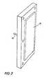
- the end plate 13includes a bladder 15 and conduit 16 through which fluid can enter in order to expand bladder 15.
- Bolt holesare provided around the periphery of the end plate in order to pass bolts thereto and to secure the entire apparatus during use.
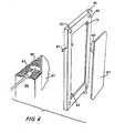
- the electrode structureis shown which comprises a rigid block 66 and an electrode 67.
- the end block 66is provided with electrolyte feed inlet 82 and electrolyte waste outlet 78.
- Electrode 67includes a connector 85 which contacts the exterior electrical connection 87 as shown in the detail portion of Figure 4.
- the block 66includes an inlet 75 and outlet 77 for depletion compartments and inlet 79 and outlet 81 for concentration compartments.
- the electrode spacer 65includes electrolyte inlet 82 and electrolyte outlet 78 and a screen 90 for effecting turbulence of liquid passing therethrough.
- the spacer formed of flexible materiale.g. spacer 38
- the spacer formed of flexible materialincludes a liquid inlet 79 and a liquid outlet 81 which provide liquid communication to the interior of spacer 38 in which is positioned a screen 95 in order to effect turbulent liquid flow.
- the outlet 99permits passage of liquid into the adjacent depleting compartments and inlet 97 permits liquid removal from the adjacent depleting compartment without admixture of the purified liquid with the liquid in the concentrating compartment formed in spacer 38.
- the depleting compartmentcomprises a rigid spacer, e.g. spacer 28, and an anion permeable membrane 30 and cation permeable membrane 26.
- the ion exchange materials 34are housed within subcompartments formed by the membranes 26 and 30, the walls 105 of the spacer 28 and the ribs 99.
- the membranes 26 and 30are sealed along their entire length to the ribs 99 and to the walls 105.
- the membranes 26 and 30are also sealed to the periphery of the rigid spacer 28 so that the individual subcompartment 98 are effectively isolated from each other.
- Liquid to be purifiedenters inlet 75, passes along conduit 100, through inlets 101 and into the subcompartments 98 wherein they are subjected to an electrical voltage in order to pass anions through membrane 30 and cations through membrane 26.
- the purified liquidthen passes through outlets 102 and spacer outlet 77 wherein it is collected in accordance with the explanation of Figure 2.
- the middle electrode block 44includes electrodes 52 and 46 each having electrical connectors 85 and 87 as shown in Figure 4.
- the connection for electrode 46is not shown in Figure 9 but is positioned on the wall 104 in the same manner as shown for electrode 52.
- Inlet 108is provided for electrolyte for electrode 46 and outlet 107 is provided for waste electrolyte utilized with electrode 52.
- the same arrangementis provided on wall 104 for the electrolyte inlet and outlet (not shown).
- Figure 10is a schematic illustration of various flows of the electrode streams of an electrodeionization apparatus assuming two electrical stages.
- inlet liquidis passed into each electrode compartment and removed therefrom in parallel.
- inlet liquidis passed into each anode compartment; removed therefrom, passed to the cathode compartment in the same electrical stage and removed from the apparatus.
- inlet liquidis passed into an anode compartment of the first stage, directed to an anode compartment in a second. electrical stage, passed to the cathode compartment of the second electrical stage, passed to the cathode compartment of the first electrical stage and then removed from the apparatus.
- liquidis passed in parallel to the anode compartment and cathode compartment of a second electrical stage.
- Liquid from the cathode compartmentis removed from the apparatus while liquid removed from the anode compartment is passed sequentially to the anode compartment and cathode compartment of an adjacent electrical stage.
- liquidis passed sequentially to the anode compartment of a first stage, the anode compartment of a second stage, the cathode compartment of the second stage and removed from the aperture.
- a second liquid stream product from a first stage depleting compartmentis passed through the cathode compartment of the second stage.
- Figure 11is a schematic illustration of various flow configurations of depleting and concentrating compartments assuming two electrical stages.
- two liquid streamsare cocurrently passed in parallel; one to all the depletion compartments sequentially and the other through the concentration compartments sequentially.
- the liquid streamare flowed as in embodiment (a) except that they are flowed countercurrently.
- a portion of the depletion stream from the first stageis cycled into the concentration stream and flowed countercurrent through the concentration compartments sequentially.
- a portion of the depletion stream from the first stage exiting from alternating depletion compartmentsare passed directly to the concentration compartment of a second stage concentration compartment.
- the first stage concentrating compartmentis fed from the original feed.
- the depleting compartmentsare fed concurrently while the first and second stage concentrating compartments are fed separately from the original feed.
- the apparatusis operated periodically during the process under conditions to polarize water in the depleting compartments therein to form hydrogen and hydroxyl ions.
- operating voltageabove about 1.5 volts/cell pair will effect water polarization.
- the hydrogen ionsare selectively removed from the depletion compartments through the cation permeable membranes thereby to decrease the pH of the water in the concentrating compartment to about 5 or less.
- any scale formed in the concentration compartmentsis dissolved.
- the low pH effluent from the anode compartmentthen can be directed to the cathode-compartment in order to dissolve any scale formed therein.
- product from the depletion compartmentsis discarded because of its elevated pH.
- the effluent from the electrode compartments formed during the scale removal stepis discarded. Normal operating voltages then are resumed and the product from the depletion compartments is recovered.
- the apparatuscan be backwashed to remove small particles retained within the apparatus, particularly within the depletion compartments. Since the inlets to the subcompartments are smaller than the size of the ion exchange materials therein, only the smaller particles are removed therefrom during backwashing.
- Backwashingmerely comprises passing cleansing liquid into the apparatus through the normally used liquid outlet(s) and removing the cleansing liquid through the normally used liquid inlet(s).
- the liquid to be purifiedcan be pretreated prior to electrodeionization to remove specific contaminants such as organics.
- a softener-scavenger systemcan be employed wherein the softener can include a cation exchange resin and/or an anion exchange resin to remove specific ions.
- the scavengercan comprise.an anion exchange resin in order to remove foulants that foul the anion resin such as organics including tannins and malignans, humic acid, fulvic acids and lignins.
- the ion exchange resinscan be regenerated with brine (NaCl) efficiently and simply.
- Suitable anion permeable membranesinclude a homogeneous type web supported styrene - divinylbenzene based with sulfonic acid or quaternary ammonium functional groups sold under the identifications CR61-CZL-386 and AR 103-QZL-386 by Ionics Inc.; a heterogeneous type web supported using styrene - divinylbenzene based resins in a polyvinylidene fluoride binder sold under the identifications MC-3470 and MA-3475 by Sybron/ lonac; homogeneous type unsupported - sulfonated styrene and quaternized vinylbenzylamine grafts of polyethylene sheet sold under the name, Raipore by RAI Research Corporation; a homogeneous type web supported styrene - divinylbenzene based with sulfonic acid or quaternary ammonium functional groups sold under the name Neosepta by Tokuyama Sod
- the process of this inventioncan be controlled by measuring product water conductivity from all or any one of the stages and adjusting the process parameters including process voltage, liquid flow velocities, temperatures, pressures, and electrical current accordingly.
- the followingis a description of two methods for controlling the demineralization of an electrodeionization system.
- the methodscan be used separately or in combination in a single or multi-electrical staged system.
- the first methodsenses the resistivity and temperature of the feed water and the appropriate cell pair voltage is applied to demineralize the liquid to the desired fraction salt removal.
- the second methodsenses the product resistivity and temperature that is used to control the voltage of the stage to produce water of the desired quality.
- This type of voltage controlcan be used to provide product water of a pre- selected quality.
- An example of a two-stage systemis as follows: The first stage is operated at a variable voltage based on the feed water quality (about 0.5 to 2.0 volts per cell pair) appropriate to achieve approxinately 7080 percent salt removal by using a predetermined resistivity/ temperature/percent salt removal relationship. The automatically applied voltage permits operation below the polarization point, thus assuring efficient operation without scaling.
- the second stageis operated at a variable voltage based on the product water quality (about 0.5 to 2.0 volts per cell pair), appropriate to provide water of a pre-selected quality. Since the feed water to the second stage is product water from the first, the second stage feed is less prone to scaling. For this reason polarization in the second stage is acceptable, and the voltage can therefore be varied to any degree to provide the required product quality.
Landscapes
- Chemical & Material Sciences (AREA)
- Chemical Kinetics & Catalysis (AREA)
- Water Supply & Treatment (AREA)
- Engineering & Computer Science (AREA)
- Life Sciences & Earth Sciences (AREA)
- Health & Medical Sciences (AREA)
- Organic Chemistry (AREA)
- Analytical Chemistry (AREA)
- Molecular Biology (AREA)
- Electrochemistry (AREA)
- General Chemical & Material Sciences (AREA)
- Hydrology & Water Resources (AREA)
- Environmental & Geological Engineering (AREA)
- Urology & Nephrology (AREA)
- Separation Using Semi-Permeable Membranes (AREA)
- Water Treatment By Electricity Or Magnetism (AREA)
Description
- This invention relates to a novel electrodeionization apparatus and method adapted to transfer ions in a liquid under the influence of a polar field. More specifically, this invention relates to an electrodeionization apparatus and method adapted to purify aqueous liquids to effect the production of high purity water.
- The purification of a liquid by reducing the concentration of ions or molecules in the liquid has been an area of substantial technological interest. Many techniques have been used to purify and isolate liquids or to obtain concentrated pools of specific ions or molecules from a liquid mixture. The most well known processes include electrodialysis, liquid chromatography, membrane filtration and ion exchange. A lesser known methodology is electrodeionization, occasionally mistermed filled cell electrodialysis. Although electrodeionization has the potential to be quite effective in removing ions from liquid, it has never been developed to the degree that it is competitive either structurally or operationally with the better known separation techniques. This is due primarily to the inconsistencies of structural design and unpredictable variances incurred by the presently known modes of use. This lack of structural design precision and nonpredictability of results have reduced the use of electrodeionization to the point where it is relatively unknown even to practitioners skilled in separation methodologies.
- The first apparatus and method for treating liquids by electrodeionization was described by Kollsman in U.S. Patent Nos. 2,689,826 and 2,815,320. The first of these patents describes an apparatus and process for the removal of ions within a liquid mixture in a depleting chamber through a series of anionic and cationic diaphragms into a second volume of liquid in a concentration chamber under the influence of an electrical potential which causes the preselected ions to travel in a predetermined direction. The volume of the liquid being treated is depleted of ions while the volume of the second liquid becomes enriched with the transferred ions and carries them in concentrated form. The second of these patents describes the use of macroporous beads formed of ion exchange resins as a filler material positioned between the anionic or cationic diaphragms. This ion exchange resin acts as a path for ion transfer and also serves as an increased conductivity bridge between the membranes for the movement of ions. These patents represent the primary structural framework and theory of electrodeionization as a technique. The term electrodeionization refers to the process wherein an ion exchange material is positioned between the anionic and cationic diaphragms. The term electrodialysis relates to such a process which does not utilize ion exchange resins between the anionic and cationic diaphragms. Despite the fact that the Kollsman technique has been available for over 25 years, this technology has not been developed even to the point of practical use. This is due in no small part to the lack of structural designs and the unavailability of operational mode parameters which afford reliable operation of the electrodeionization apparatus. Illustrative of prior art attempts to use the combination of electrodialysis and ion exchange materials to resins to purify saline from brackish water are described in U.S. Ratent Nos. 2,794,777; 2,796,395; 2,947,688; 3,384,568 and 4,165,273. Attempts to improve electrodeionization apparatus are shown in U.S. Patent Nos. 3,149,061; 3,291,713; 3,515,664; 3,562,139; 3,993,517 and 4,284,492.
- Despite the contributions of the prior art, no reliable electrodeionization apparatus has been produced. The typical resin fouling and membrane scaling problems of electrodeionization remain unalleviated. presently described electrodeionization apparatus remain unsuitable for desalination or for the production of high purity water. Hard waters, silica-containing waters and highly saline brackish waters, and waters containing colloidal particles and foulants still represent liquids that cannot be consistently and reliably purified by presently known electrodeionization apparatus and modes of operation. Extensive maintenance and cleaning of these apparatus remain necessary, the quality and volume of the purified liquids remain erratic and the ability to produce at least 1 mega-ohm centimeter quality water consistently and in sufficient volume remain unachieved.
- Accordingly, it would be desirable to provide a method and apparatus utilizing electrodeionization capable of producing a high purity deionized water over long periods of time without the need for shutting down the apparatus either because of reduction of ion exchange resin performance or because of particle or scale build-up. Furthermore, it would be desirable to provide such a method and apparatus which can be operated efficiently with low energy requirements and high liquid throughput.
- The present invention provides a method and apparatus capable of continuously producing water of up to about 10 mega-ohm cm quality or higher over long periods of time while avoiding serious reduction of ion exchange resin performance and avoiding the build-up of particulates and scale within the electrodeionization apparatus. The apparatus includes a plurality of electrodeionization compartments whose thickness, width and configuration are controlled and which contain ion exchange materials such as beads, fibers or the like. The electrodeionization ion depleting compartments wherein liquid is depleted of ions are formed from a spacer having a hollow central portion divided by ribs to define subcompartments. The ion exchange resin beads within the subcompartments are retained in the subcompartments by bonding or physically restraining a cationic permeable membrane to one surface of the depleting compartments and to the ribs and bonding or physically restraining an anionic permeable membrane to the opposing surface of the depleting compartment to the ribs, thereby to define the subcompartments. The concentration compartments into which ions migrate from the depleting compartments are free of ion exchange beads. The electrodeionization apparatus can comprise a single stage or a-plurality of stages in series wherein the process voltage can be controlled independently in each stage, if desired.
- Figure 1 is an exploded view of a multistage electrodeionization apparatus of this invention.
- Figure 2 is a schematic view illustrating the operation of the apparatus of this invention.
- Figure 3 is a pictorial view of a closing mechanism useful in the apparatus of this invention.
- Figure 4 is a pictorial view of an electrode structure useful in the apparatus of this invention.
- Figure 5 is a pictorial view of a spacer construction positioned adjacent an electrode of the apparatus of this invention.
- Figure 6 is a pictorial view of a flexible spacer construction which includes the concentration chambers of the apparatus of this invention.
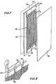
- Figure 7 is a pictorial view showing the depletion chambers of the apparatus of this invention.
- Figure 8 is a detailed view of the liquid inlet means to the structure of Figure 7.
- Figure 9 is a pictorial view of an interior electrode assembly utilized in the plural stage embodiment of the apparatus of this invention.
- Figure 10 is a schematic diagram showing possible liquid flow paths of electrode stream flows between electrical stages of this invention.
- Figure 11 is a schematic diagram showing possible liquid flow paths for depletion and concentration compartments for each electrical stage.
- The invention relates to an electrodeionizition apparatus according to claim 1. The invention further relates to a process for removing ions from a liquid by means of said apparatus.
- In accordance with this invention, an electrodeionization apparatus is provided wherein each electrodeionization electrical stage includes an anode and a cathode, and their compartments, series of concentration compartments which include means for causing turbulent flow of liquid passing therethrough and a series of depletion compartments that contain an ion exchange material such as a mixture of anion exchange resin and cation exchange resin. The depletion compartments are formed so that the ion exchange resin mixture is housed within independent discrete subcompartments each of which has a width of preferably between 1.27 and 3.81 cm (0.5 and 1.5 inches). The discrete subcompartments are formed by securing, such as by bonding, both the anion permeable membrane and the cation permeable membrane to the periphery of the depletion compartment and to ribs which extend across the thickness of and along the entire length of the depletion compartment so that each subcompartment is defined by a pair of ribs, the anion permeable exchange membrane and the cation permeable membrane. It has been found, in accordance with this invention that the thickness and width of the depletion compartments are critical to achieving efficient operation of the electrodeionization apparatus. The solid ion exchange material positioned within the subcompartments are constrained from moving between subcompartments by the ribs and ion permeable membranes. Representative suitable solid ion exchange materials include fibers or beads or the like. When employing ion exchange beads, typical bead diameter is 2.54 x 0.4 cm (0.4 inches) or less, preferably between 2.54 x .033 and 2.54 x .012 cm (.033 and .012 inches) in diameter [.510 to .207 mm (20 to 50 mesh)].
- The electrodeionization apparatus can comprise one or a plurality of stages. In each stage, an anode is positioned at an opposite end of a stack of depleting and concentrating compartments from an end at which a cathode is positioned. Each anode and cathode is provided with an adjacent electrode spacer and an ion permeable membrane wherein an electrolyte passes through the electrode spacer. The remaining portion of each stage comprises a series of alternating depletion and concentrating compartments constructed as set forth herein. The liquid to be depleted of ions can be passed in parallel through each depleting compartment in each stage and a second liquid can be passed through each concentrating compartment in parallel in each stage in order to effect removal of ions from the first liquid in the depleting compartments into the second liquid in the concentrating compartments. When a plurality of stages are utilized, the liquid removed from the depleting compartments in an upstream stage can be directed in series into the depleting compartments in the next adjacent downstream stage. Similarly, the liquid removed from the concentrating compartments of an upstream stage can be directed in series to the concentrating compartments in the next adjacent downstream stage. Electrolyte can be passed through the spacer adjacent each electrode in the electrodeionization apparatus and is removed from the electrodeionization apparatus. Other possible liquid flow arrangements will be discussed in detail with reference to Figures 10 and 11.
- As stated above it is essential that the subcompartments in the depleting compartments have a controlled thickness and width in order to sustain high efficiency for ion depletion over long periods. The thickness of the subcompartment must be between 0.127 and 0.635 cm (0.25 and 0.05 inches), preferably between 2.54 x .06 and 2.54 x .125 cm (.06 and .125 inches). The width of the subcompartment must be between 0.762 and 10.16 cm (0.3 and 4 inches), preferably between 2.54 x .5 and 2.54 x 1.5 cm (.5 and 1.5 inches). There is no limit on the length of the compartment other than as dictated by practical construction and fluid pressure loss considerations. Obviously, the longer the subcompartment length, the greater the ion removal from the liquid therein. Generally, the length of the subcompartments are between 2.54 x 5 and 2.54 x 70 cm (5 inches and 70 inches). The subcompartments can contain 100% anion exchange material, 100% cation exchange material or a mixture of the two. When it is desired to remove only a particular anion or particular cation, 100% of the appropriate ion exchange material is used. Usually it is desired to remove both cations and anions in order to produce a purified liquid product. When utilizing strong acid-base resin materials such as beads, the ratio of anion exchange resin beads to cation exchange resin beads generally are about 60 to 40 by volume. By utilizing the subcompartment structure in the depleting compartments, efficient mixing of the liquid and the beads therein is attained while avoiding channeling of the liquid through the depleting compartments as well as avoiding compaction or movement of the beads within a portion of the volume of the depleting compartment. Thus, efficient interchange of the ions and the liquid in the depleting compartment with the ions in the beads to effect ion removal from the liquid in the depleting compartment is attained. Furthermore, it has been found that by controlling the geometry of the subcompartments as set forth herein, relatively low energy requirements for the electrodeionization apparatus can be utilized even over long periods to attain desired liquid purity.
- This invention will now be described with reference to the accompanying drawings. A multistage electrodeionization apparatus is shown in Figure 1.
- Referring to Figure 1, the electrodeionization apparatus 10 comprises a
first stage 12 and asecond stage 14. Thefirst stage 12 includes anend plate 13 having anexpandable bladder 15 and aninlet 16 for fluid to expand thebladder 15. Adjacent theendplate 13 is anendblock 17 tohouse electrode 9 and provide desired manifolding. Anelectrode spacer 18 is positioned adjacent to theend block 17 and includes ascreen 19 which effects turbulent flow of liquid passing through theelectrode spacer 18. An ionpermeable membrane 20 is sealed to theperiphery 21 ofelectrode spacer 18. Aspacer 22 formed of flexible material includes ascreen 24. Thespacer 22 andscreen 24 comprise the concentrating compartment of the electrodeionization apparatus of this invention. The depleting compartment structure of this invention comprises an ionpermeable membrane 26, a spacer formed ofrigid material 28 and an ionpermeable membrane 30. The ionpermeable membranes periphery 32 of thespacer 28 on opposite surfaces of thespacer 28. Mixed ionexchange resin beads 34 are housed within a central space which includes ribs (not shown) and are retained therein by themembranes spacers membranes stage 12. Aspacer 38 formed of flexible material andion exchange membrane 40 sealed to the periphery ofspacer 38 forms the end concentrating compartment. Anelectrode spacer 42 is positioned adjacent themiddle block 44 andend electrode 46. Stage 14 is identical in structure to stage 12 but can have more or fewer cell pairs and includeselectrode spacer 48 andmembrane 50 attached to the periphery ofelectrode spacer 48. Anelectrode 52 is provided inmiddle block 44. The repeating unit instage 14 comprises aspacer 54 formed of flexible material as well as aspacer 56 formed of rigid material to which are secured such as by bonding or bymechanical means membranes spacer 61 formed of flexible material then is provided followed by amembrane 63, anelectrode spacer 65, andendblock 66 andelectrode 67, anend plate 68 and aflexible bladder 70 which is inflated by means of fluid passing throughconduit 72. Flowthrough of liquid in the concentrating and depleting compartments as well as in the electrode compartment will be explained with reference to the remaining figures. The electrodeionization apparatus is retained in place by bolts 73 and 74 as well as by bolts on the opposing end of the apparatus 10 that extend along the entire length of the apparatus 10. The number of repeating units in thesecond stage 14 is usually about 5 and about 100, preferably between about 20 and about 60.- By independently varying voltage, electrical current can be controlled in each stage to provide good economy and efficiency for the overall electrodeionization process. Alternatively, a
single stage 14 can be utilized as the apparatus of this invention or additional stages can also be utilized. In any event, the flow rate of liquid through the depleting and concentrating compartments and the operating voltage utilized in a particular stage is controlled to maximize efficiency for the overall apparatus in terms of ion removal and electrical power utilized. - Referring to Figure 2, the flowpaths of the liquids in the various compartment are explained. Liquid to be purified enters
inlet 75, passes throughdepletion compartments 28, is then passed throughdepletion compartments 56 and is recovered fromoutlet 77. Concentrating liquid is passed throughoutlet 79 through concentratingcompartments outlet 81 to drain. Liquid electrolyte is circulated throughelectrode compartments - Referring to Figure 3, the
end plate 13 includes abladder 15 andconduit 16 through which fluid can enter in order to expandbladder 15. Bolt holes are provided around the periphery of the end plate in order to pass bolts thereto and to secure the entire apparatus during use. - Referring to Figure 4, the electrode structure is shown which comprises a
rigid block 66 and anelectrode 67. Theend block 66 is provided with electrolyte feed inlet 82 and electrolyte waste outlet 78.Electrode 67 includes aconnector 85 which contacts the exteriorelectrical connection 87 as shown in the detail portion of Figure 4. Theblock 66 includes aninlet 75 andoutlet 77 for depletion compartments andinlet 79 andoutlet 81 for concentration compartments. - Referring to Figure 5, the
electrode spacer 65 includes electrolyte inlet 82 and electrolyte outlet 78 and ascreen 90 for effecting turbulence of liquid passing therethrough. - Referring to Figure 6, the spacer formed of flexible material,
e.g. spacer 38, includes aliquid inlet 79 and aliquid outlet 81 which provide liquid communication to the interior ofspacer 38 in which is positioned ascreen 95 in order to effect turbulent liquid flow. Theoutlet 99 permits passage of liquid into the adjacent depleting compartments andinlet 97 permits liquid removal from the adjacent depleting compartment without admixture of the purified liquid with the liquid in the concentrating compartment formed inspacer 38. - Referring to Figures 7 and 8, the structure of the depleting compartments of this invention is shown in detail. The depleting compartment comprises a rigid spacer,
e.g. spacer 28, and an anionpermeable membrane 30 and cationpermeable membrane 26. Theion exchange materials 34 are housed within subcompartments formed by themembranes walls 105 of thespacer 28 and theribs 99. Themembranes ribs 99 and to thewalls 105. Themembranes rigid spacer 28 so that theindividual subcompartment 98 are effectively isolated from each other. Liquid to be purified entersinlet 75, passes alongconduit 100, throughinlets 101 and into thesubcompartments 98 wherein they are subjected to an electrical voltage in order to pass anions throughmembrane 30 and cations throughmembrane 26. The purified liquid then passes throughoutlets 102 andspacer outlet 77 wherein it is collected in accordance with the explanation of Figure 2. - Referring to Figure 9, the
middle electrode block 44 includeselectrodes electrical connectors electrode 46 is not shown in Figure 9 but is positioned on thewall 104 in the same manner as shown forelectrode 52.Inlet 108 is provided for electrolyte forelectrode 46 andoutlet 107 is provided for waste electrolyte utilized withelectrode 52. The same arrangement is provided onwall 104 for the electrolyte inlet and outlet (not shown). - Figure 10, is a schematic illustration of various flows of the electrode streams of an electrodeionization apparatus assuming two electrical stages. In embodiment (a), inlet liquid is passed into each electrode compartment and removed therefrom in parallel. In embodiment (b), inlet liquid is passed into each anode compartment; removed therefrom, passed to the cathode compartment in the same electrical stage and removed from the apparatus. In embodiment (c), inlet liquid is passed into an anode compartment of the first stage, directed to an anode compartment in a second. electrical stage, passed to the cathode compartment of the second electrical stage, passed to the cathode compartment of the first electrical stage and then removed from the apparatus. In embodiment (d) liquid is passed in parallel to the anode compartment and cathode compartment of a second electrical stage. Liquid from the cathode compartment is removed from the apparatus while liquid removed from the anode compartment is passed sequentially to the anode compartment and cathode compartment of an adjacent electrical stage. In embodiment (e) liquid is passed sequentially to the anode compartment of a first stage, the anode compartment of a second stage, the cathode compartment of the second stage and removed from the aperture. A second liquid stream product from a first stage depleting compartment is passed through the cathode compartment of the second stage.
- Figure 11 is a schematic illustration of various flow configurations of depleting and concentrating compartments assuming two electrical stages. In embodiment (a) of Figure 11 two liquid streams are cocurrently passed in parallel; one to all the depletion compartments sequentially and the other through the concentration compartments sequentially. In embodiment (b) the liquid stream are flowed as in embodiment (a) except that they are flowed countercurrently. In embodiment (c) a portion of the depletion stream from the first stage is cycled into the concentration stream and flowed countercurrent through the concentration compartments sequentially. In embodiment (d) a portion of the depletion stream from the first stage exiting from alternating depletion compartments are passed directly to the concentration compartment of a second stage concentration compartment. The first stage concentrating compartment is fed from the original feed. In embodiment (e) the depleting compartments are fed concurrently while the first and second stage concentrating compartments are fed separately from the original feed.
- In one aspect of this invention, the apparatus is operated periodically during the process under conditions to polarize water in the depleting compartments therein to form hydrogen and hydroxyl ions. Generally, operating voltage above about 1.5 volts/cell pair will effect water polarization. The hydrogen ions are selectively removed from the depletion compartments through the cation permeable membranes thereby to decrease the pH of the water in the concentrating compartment to about 5 or less. By operating in this manner any scale formed in the concentration compartments is dissolved. The low pH effluent from the anode compartment then can be directed to the cathode-compartment in order to dissolve any scale formed therein. During this step product from the depletion compartments is discarded because of its elevated pH. The effluent from the electrode compartments formed during the scale removal step is discarded. Normal operating voltages then are resumed and the product from the depletion compartments is recovered.
- In another aspect of this invention, the apparatus can be backwashed to remove small particles retained within the apparatus, particularly within the depletion compartments. Since the inlets to the subcompartments are smaller than the size of the ion exchange materials therein, only the smaller particles are removed therefrom during backwashing. Backwashing merely comprises passing cleansing liquid into the apparatus through the normally used liquid outlet(s) and removing the cleansing liquid through the normally used liquid inlet(s).
- In a third aspect of this invention, the liquid to be purified can be pretreated prior to electrodeionization to remove specific contaminants such as organics. A softener-scavenger system can be employed wherein the softener can include a cation exchange resin and/or an anion exchange resin to remove specific ions. The scavenger can comprise.an anion exchange resin in order to remove foulants that foul the anion resin such as organics including tannins and malignans, humic acid, fulvic acids and lignins. The ion exchange resins can be regenerated with brine (NaCl) efficiently and simply.
- Any anion permeable membrane or cation permeable membrane having the strength to withstand the operating pressure differential, typically up to about 5 x 6.895 x 103 Pa (5 psi), can be utilized in the present invention. It should be pointed out that sealing of the membranes to the ribs forming the subcompartments permits the use of higher operating pressures and enhances the apparatus of the prior art since the assembly strength is thereby increased. Representative suitable anion permeable membranes include a homogeneous type web supported styrene - divinylbenzene based with sulfonic acid or quaternary ammonium functional groups sold under the identifications CR61-CZL-386 and AR 103-QZL-386 by Ionics Inc.; a heterogeneous type web supported using styrene - divinylbenzene based resins in a polyvinylidene fluoride binder sold under the identifications MC-3470 and MA-3475 by Sybron/ lonac; homogeneous type unsupported - sulfonated styrene and quaternized vinylbenzylamine grafts of polyethylene sheet sold under the name, Raipore by RAI Research Corporation; a homogeneous type web supported styrene - divinylbenzene based with sulfonic acid or quaternary ammonium functional groups sold under the name Neosepta by Tokuyama Soda Co. Ltd.; a homogeneous type web supported styrene - divinylbenzene based with sulfonic acid or quaternary ammonium functional groups sold under the name Aciplex by Asahi Chemical Industry Co. Ltd.
- The process of this invention can be controlled by measuring product water conductivity from all or any one of the stages and adjusting the process parameters including process voltage, liquid flow velocities, temperatures, pressures, and electrical current accordingly.
- The following is a description of two methods for controlling the demineralization of an electrodeionization system. The methods can be used separately or in combination in a single or multi-electrical staged system. The first method senses the resistivity and temperature of the feed water and the appropriate cell pair voltage is applied to demineralize the liquid to the desired fraction salt removal.
- The second method senses the product resistivity and temperature that is used to control the voltage of the stage to produce water of the desired quality. This type of voltage control can be used to provide product water of a pre- selected quality.
- An example of a two-stage system is as follows: The first stage is operated at a variable voltage based on the feed water quality (about 0.5 to 2.0 volts per cell pair) appropriate to achieve approxinately 7080 percent salt removal by using a predetermined resistivity/ temperature/percent salt removal relationship. The automatically applied voltage permits operation below the polarization point, thus assuring efficient operation without scaling. The second stage is operated at a variable voltage based on the product water quality (about 0.5 to 2.0 volts per cell pair), appropriate to provide water of a pre-selected quality. Since the feed water to the second stage is product water from the first, the second stage feed is less prone to scaling. For this reason polarization in the second stage is acceptable, and the voltage can therefore be varied to any degree to provide the required product quality.
Claims (15)
characterized in that each of said ion depletion compartments comprises a spacer having a hollow central portion divided by a plurality of ribs extending along the length of each of said ion depletion compartment to define a plurality of subcompartments, each of said subcompartments containing an ion exchange solid composition, which is retained in the subcompartments by bonding an ion permeable membrane and a cation permeable membrane to the spacer and to each of said ribs, along the length of said ribs, on opposite surfaces with respect to the spacer, each of said subcompartments having a width defined by the distance between said ribs of between 0.762 and 10.16 cm and a thickness between 0.127 and 0.635 cm, wherein the thickness of said subcompartments is defined by the distance between the anion permeable membrane and the cation permeable membrane.
Applications Claiming Priority (2)
| Application Number | Priority Date | Filing Date | Title |
|---|---|---|---|
| US62893084A | 1984-07-09 | 1984-07-09 | |
| US628930 | 1984-07-09 |
Publications (3)
| Publication Number | Publication Date |
|---|---|
| EP0170895A2 EP0170895A2 (en) | 1986-02-12 |
| EP0170895A3 EP0170895A3 (en) | 1986-10-08 |
| EP0170895B1true EP0170895B1 (en) | 1989-03-22 |
Family
ID=24520897
Family Applications (1)
| Application Number | Title | Priority Date | Filing Date |
|---|---|---|---|
| EP85108378AExpiredEP0170895B1 (en) | 1984-07-09 | 1985-07-05 | Improved electrodeionization apparatus and method |
Country Status (4)
| Country | Link |
|---|---|
| US (1) | US4632745B1 (en) |
| EP (1) | EP0170895B1 (en) |
| JP (1) | JPS61107906A (en) |
| DE (1) | DE3568946D1 (en) |
Cited By (30)
| Publication number | Priority date | Publication date | Assignee | Title |
|---|---|---|---|---|
| EP0346502A1 (en)* | 1988-05-31 | 1989-12-20 | Millipore Corporation | Electrodeionization method and apparatus |
| EP0417506A1 (en)* | 1989-09-08 | 1991-03-20 | Millipore Corporation | Electrodeionization and ultraviolet light treatment method for purifying water |
| EP0422453A3 (en)* | 1989-10-06 | 1991-05-08 | Millipore Corporation | Process for purifying water |
| EP0379116A3 (en)* | 1989-01-18 | 1991-06-12 | Millipore Corporation | Electrodeionization apparatus and module |
| DE4027526A1 (en)* | 1990-08-31 | 1992-03-05 | K D Pharma Gmbh | METHOD FOR REDUCING THE CONCENTRATION OF A SOLUTION ON A SPECIFIC ION OR A SPECIFIC GROUP OF IONS |
| GB2289059A (en)* | 1994-05-06 | 1995-11-08 | Atomic Energy Authority Uk | Electrochemical deionisation using electrochemical ion-exchange to remove ions from feed solution or in cathodic protection of reinforcing bars in concrete |
| US5512173A (en)* | 1993-04-21 | 1996-04-30 | Nippon Rensui Co. | Demineralization apparatus and cloth for packing diluting chamber of the demineralization apparatus |
| US5584981A (en)* | 1994-05-06 | 1996-12-17 | United Kingdom Atomic Energy Authority | Electrochemical deionization |
| US5954935A (en)* | 1994-05-30 | 1999-09-21 | Forschuugszentrum Julich GmbH | Electrolytic cell arrangement for the deionization of aqueous solutions |
| GB2355213A (en)* | 1999-05-07 | 2001-04-18 | United States Filter Corp | Apparatus and method of recirculating electrodeionisation |
| SG83198A1 (en)* | 1999-03-25 | 2001-09-18 | Organo Corp | An electrodeionization apparatus comprising sub-desalination chambers |
| US6338784B1 (en) | 1997-02-27 | 2002-01-15 | Asahi Glass Company Ltd. | Apparatus for producing deionized water |
| US6471867B2 (en) | 1999-12-10 | 2002-10-29 | Asahi Glass Company, Limited | Electro-regenerating type apparatus for producing deionized water |
| US6482304B1 (en) | 1999-05-07 | 2002-11-19 | Otv Societe Anonyme | Apparatus and method of recirculating electrodeionization |
| US7147785B2 (en) | 2000-09-28 | 2006-12-12 | Usfilter Corporation | Electrodeionization device and methods of use |
| US7329358B2 (en) | 2004-05-27 | 2008-02-12 | Siemens Water Technologies Holding Corp. | Water treatment process |
| US7371319B2 (en) | 2002-10-23 | 2008-05-13 | Siemens Water Technologies Holding Corp. | Production of water for injection using reverse osmosis |
| US7572359B2 (en) | 2001-10-15 | 2009-08-11 | Siemens Water Technologies Holding Corp. | Apparatus for fluid purification and methods of manufacture and use thereof |
| US7658828B2 (en) | 2005-04-13 | 2010-02-09 | Siemens Water Technologies Holding Corp. | Regeneration of adsorption media within electrical purification apparatuses |
| US7744760B2 (en) | 2006-09-20 | 2010-06-29 | Siemens Water Technologies Corp. | Method and apparatus for desalination |
| US7820024B2 (en) | 2006-06-23 | 2010-10-26 | Siemens Water Technologies Corp. | Electrically-driven separation apparatus |
| US8045849B2 (en) | 2005-06-01 | 2011-10-25 | Siemens Industry, Inc. | Water treatment system and process |
| US8114260B2 (en) | 2003-11-13 | 2012-02-14 | Siemens Industry, Inc. | Water treatment system and method |
| US9011660B2 (en) | 2007-11-30 | 2015-04-21 | Evoqua Water Technologies Llc | Systems and methods for water treatment |
| US9023185B2 (en) | 2006-06-22 | 2015-05-05 | Evoqua Water Technologies Llc | Low scale potential water treatment |
| US9592472B2 (en) | 2006-06-13 | 2017-03-14 | Evoqua Water Technologies Llc | Method and system for irrigation |
| US10252923B2 (en) | 2006-06-13 | 2019-04-09 | Evoqua Water Technologies Llc | Method and system for water treatment |
| US10625211B2 (en) | 2006-06-13 | 2020-04-21 | Evoqua Water Technologies Llc | Method and system for water treatment |
| US11820689B2 (en) | 2017-08-21 | 2023-11-21 | Evoqua Water Technologies Llc | Treatment of saline water for agricultural and potable use |
| US12180103B2 (en) | 2017-08-21 | 2024-12-31 | Evoqua Water Technologies Llc | Treatment of saline water for agricultural and potable use and for generation of disinfectant solution |
Families Citing this family (161)
| Publication number | Priority date | Publication date | Assignee | Title |
|---|---|---|---|---|
| US4931160A (en)* | 1987-05-11 | 1990-06-05 | Millipore Corporation | Electrodeionization method and apparatus |
| USRE35741E (en)* | 1984-07-09 | 1998-03-10 | Millipore Corporation | Process for purifying water |
| US4734181A (en)* | 1984-12-07 | 1988-03-29 | The Dow Chemical Company | Electrochemical cell |
| US4781809A (en)* | 1986-07-21 | 1988-11-01 | Ionics, Incorporated | Recovering free organic acids from solutions in which they occur with other organic matter |
| US4804451A (en)* | 1986-10-01 | 1989-02-14 | Millipore Corporation | Depletion compartment for deionization apparatus and method |
| US4747929A (en)* | 1986-10-01 | 1988-05-31 | Millipore Corporation | Depletion compartment and spacer construction for electrodeionization apparatus |
| JPH044817Y2 (en)* | 1987-08-11 | 1992-02-12 | ||
| JPH0620513B2 (en)* | 1988-06-03 | 1994-03-23 | ミリポア・コーポレイション | Electrodeionization method and apparatus |
| JPH0759296B2 (en)* | 1988-07-27 | 1995-06-28 | 栗田工業株式会社 | Pure water production equipment |
| US5254227A (en)* | 1989-06-16 | 1993-10-19 | Olin Corporation | Process for removing catalyst impurities from polyols |
| DE69120295T2 (en)* | 1990-12-17 | 1997-03-06 | Ionpure Filter Us Inc | ELECTRODEIONIZING DEVICE |
| DE69204187T2 (en)* | 1991-03-13 | 1996-01-25 | Ebara Corp | Electrically regenerable demineralization device. |
| JP2504885B2 (en)* | 1991-11-12 | 1996-06-05 | 日本原子力研究所 | Ion exchanger manufacturing method |
| US5292422A (en)* | 1992-09-15 | 1994-03-08 | Ip Holding Company | Modules for electrodeionization apparatus |
| DE4244060A1 (en)* | 1992-12-24 | 1994-06-30 | Gruenbeck Josef Wasseraufb | Process and plant for treating an aqueous solution by ion exchange |
| US5503729A (en)* | 1994-04-25 | 1996-04-02 | Ionics Incorporated | Electrodialysis including filled cell electrodialysis (electrodeionization) |
| JPH10500617A (en)* | 1994-05-20 | 1998-01-20 | ユー・エス・フィルター/アイオンピュア・インコーポレーテッド | Electrode-ionization devices with polarity reversal and double reversal and their use |
| AUPM807194A0 (en)* | 1994-09-09 | 1994-10-06 | Ici Australia Operations Proprietary Limited | Water treatment process |
| AUPM959994A0 (en)* | 1994-11-22 | 1994-12-15 | Ici Australia Operations Proprietary Limited | Water treatment process |
| US5935443A (en) | 1995-03-03 | 1999-08-10 | Alltech Associates, Inc. | Electrochemically regenerated ion neutralization and concentration devices and systems |
| AU710548B2 (en)* | 1995-03-03 | 1999-09-23 | Dionex Corporation | Apparatus/method for electrochemically modifying chromatographic material |
| TW426644B (en)* | 1996-03-21 | 2001-03-21 | Asahi Glass Co Ltd | Method and apparatus for producing deionized water |
| US5593563A (en) | 1996-04-26 | 1997-01-14 | Millipore Corporation | Electrodeionization process for purifying a liquid |
| US5681438A (en)* | 1996-05-31 | 1997-10-28 | Millipore Corporation | Membrane module assembly |
| US5868915A (en)* | 1996-09-23 | 1999-02-09 | United States Filter Corporation | Electrodeionization apparatus and method |
| ES2232850T3 (en)* | 1996-10-09 | 2005-06-01 | Societe Des Produits Nestle S.A. | DEMINERALIZATION OF PRODUCTS AND DAIRY DERIVATIVES. |
| EP0835609B1 (en)* | 1996-10-09 | 2004-06-23 | Societe Des Produits Nestle S.A. | Demineralisation of sweet cheese whey |
| NZ328836A (en)* | 1996-10-09 | 1999-02-25 | Nestle Sa | Process for demineralization of sweet whey by electrodeionization in an apparatus containing dilution and concentration departments |
| EP0835610B1 (en)* | 1996-10-09 | 2004-12-08 | Societe Des Produits Nestle S.A. | Demineralisation of milk products or milk derivatives |
| ES2353254T3 (en) | 1996-12-20 | 2011-02-28 | Siemens Water Technologies Corp. | WASHING PROCEDURE |
| WO1998051620A1 (en)* | 1997-05-09 | 1998-11-19 | Usf Filtration And Separations Group Inc. | Purification of a liquid stream |
| AUPO671597A0 (en)* | 1997-05-09 | 1997-06-05 | Crc For Waste Management And Pollution Control Limited | Electrochemical regeneration of ion exchange resin |
| US6641733B2 (en) | 1998-09-25 | 2003-11-04 | U. S. Filter Wastewater Group, Inc. | Apparatus and method for cleaning membrane filtration modules |
| US6017433A (en)* | 1997-11-12 | 2000-01-25 | Archer Daniels Midland Company | Desalting aqueous streams via filled cell electrodialysis |
| ATE413365T1 (en) | 1998-03-24 | 2008-11-15 | Ebara Corp | ELECTRICAL DENITIONIZER DEVICE |
| US6149788A (en)* | 1998-10-16 | 2000-11-21 | E-Cell Corporation | Method and apparatus for preventing scaling in electrodeionization units |
| US6284124B1 (en) | 1999-01-29 | 2001-09-04 | United States Filter Corporation | Electrodeionization apparatus and method |
| AUPP985099A0 (en) | 1999-04-20 | 1999-05-13 | Usf Filtration And Separations Group Inc. | Membrane filtration manifold system |
| US6254753B1 (en) | 1999-09-13 | 2001-07-03 | Leon Mir | High purity electrodeionization |
| US6187162B1 (en) | 1999-09-13 | 2001-02-13 | Leon Mir | Electrodeionization apparatus with scaling control |
| US6241867B1 (en) | 1999-09-13 | 2001-06-05 | Leon Mir | Electrodeionization apparatus and packing therefor |
| US6241866B1 (en) | 1999-09-13 | 2001-06-05 | Leon Mir | Electrodeionization apparatus with fixed ion exchange materials |
| US6296751B1 (en) | 1999-09-13 | 2001-10-02 | Leon Mir | Electrodeionization apparatus with scaling control |
| KR100692698B1 (en) | 1999-11-02 | 2007-03-09 | 쿠리타 고교 가부시키가이샤 | Electric deionizer and electric deionization treatment method using the same |
| US6284117B1 (en) | 1999-12-22 | 2001-09-04 | Nanogen, Inc. | Apparatus and method for removing small molecules and ions from low volume biological samples |
| AUPQ680100A0 (en) | 2000-04-10 | 2000-05-11 | Usf Filtration And Separations Group Inc. | Hollow fibre restraining system |
| DE60143351D1 (en) | 2000-05-10 | 2010-12-09 | Millipore Corp | IMPROVED ELECTRIC INSULATION MODULE |
| JP4497388B2 (en)* | 2000-05-15 | 2010-07-07 | オルガノ株式会社 | Electric deionized water production apparatus and deionized water production method |
| US6365023B1 (en) | 2000-06-22 | 2002-04-02 | Millipore Corporation | Electrodeionization process |
| GB0016846D0 (en) | 2000-07-10 | 2000-08-30 | United States Filter Corp | Electrodeionisation Apparatus |
| CN100522323C (en)* | 2000-08-11 | 2009-08-05 | 艾奥尼克斯公司 | Device and method for electrodialysis |
| AUPR064800A0 (en) | 2000-10-09 | 2000-11-02 | Usf Filtration And Separations Group Inc. | Improved membrane filtration system |
| AUPR143400A0 (en) | 2000-11-13 | 2000-12-07 | Usf Filtration And Separations Group Inc. | Modified membranes |
| DE10104771A1 (en)* | 2001-02-02 | 2002-08-08 | Basf Ag | Method and device for deionizing cooling media for fuel cells |
| AUPR421501A0 (en) | 2001-04-04 | 2001-05-03 | U.S. Filter Wastewater Group, Inc. | Potting method |
| US6709560B2 (en)* | 2001-04-18 | 2004-03-23 | Biosource, Inc. | Charge barrier flow-through capacitor |
| US6607647B2 (en) | 2001-04-25 | 2003-08-19 | United States Filter Corporation | Electrodeionization apparatus with expanded conductive mesh electrode and method |
| US6649037B2 (en) | 2001-05-29 | 2003-11-18 | United States Filter Corporation | Electrodeionization apparatus and method |
| AUPR584301A0 (en) | 2001-06-20 | 2001-07-12 | U.S. Filter Wastewater Group, Inc. | Membrane polymer compositions |
| WO2003009920A1 (en) | 2001-07-25 | 2003-02-06 | Biosource, Inc. | Electrode array for use in electrochemical cells |
| AUPR692401A0 (en) | 2001-08-09 | 2001-08-30 | U.S. Filter Wastewater Group, Inc. | Method of cleaning membrane modules |
| AUPR774201A0 (en) | 2001-09-18 | 2001-10-11 | U.S. Filter Wastewater Group, Inc. | High solids module |
| US7794577B2 (en)* | 2001-11-16 | 2010-09-14 | Ionics, Incorporated | Spacer for filled cell electrodialysis |
| EP1312408B1 (en) | 2001-11-16 | 2006-07-19 | US Filter Wastewater Group, Inc. | Method of cleaning membranes |
| PL374239A1 (en)* | 2001-12-21 | 2005-10-03 | Dow Global Technologies Inc. | Additive for rendering inert acidic or halogen-containing compounds contained in olefin polymers |
| US20050011409A1 (en)* | 2001-12-25 | 2005-01-20 | Yasuhide Isobe | Inorganic oxide |
| AUPR987802A0 (en) | 2002-01-08 | 2002-01-31 | Commonwealth Scientific And Industrial Research Organisation | Complexing resins and method for preparation thereof |
| US7094325B2 (en)* | 2002-02-02 | 2006-08-22 | Ionics, Incorporated | EDI and related stacks and method and apparatus for preparing such |
| US7247238B2 (en) | 2002-02-12 | 2007-07-24 | Siemens Water Technologies Corp. | Poly(ethylene chlorotrifluoroethylene) membranes |
| US6808608B2 (en)* | 2002-03-13 | 2004-10-26 | Dionex Corporation | Water purifier and method |
| US6758954B2 (en)* | 2002-04-11 | 2004-07-06 | U.S. Filter Corporation | Electrodeionization apparatus with resilient endblock |
| AUPS300602A0 (en) | 2002-06-18 | 2002-07-11 | U.S. Filter Wastewater Group, Inc. | Methods of minimising the effect of integrity loss in hollow fibre membrane modules |
| KR101002466B1 (en) | 2002-10-10 | 2010-12-17 | 지멘스 워터 테크놀로지스 코포레이션 | Back wash method |
| JP3956836B2 (en) | 2002-11-15 | 2007-08-08 | 栗田工業株式会社 | Electrodeionization equipment |
| AU2002953111A0 (en) | 2002-12-05 | 2002-12-19 | U. S. Filter Wastewater Group, Inc. | Mixing chamber |
| US6929748B2 (en)* | 2003-03-28 | 2005-08-16 | Chemitreat Pte Ltd | Apparatus and method for continuous electrodeionization |
| AU2003901583A0 (en) | 2003-04-04 | 2003-05-01 | Orica Australia Pty Ltd | A process |
| US7763157B2 (en)* | 2003-04-11 | 2010-07-27 | Millipore Corporation | Electrodeionization device |
| US7404884B2 (en)* | 2003-04-25 | 2008-07-29 | Siemens Water Technologies Holding Corp. | Injection bonded articles and methods |
| AU2003903507A0 (en)* | 2003-07-08 | 2003-07-24 | U. S. Filter Wastewater Group, Inc. | Membrane post-treatment |
| US7344629B2 (en)* | 2003-08-08 | 2008-03-18 | Pionetics Corporation | Selectable ion concentrations with electrolytic ion exchange |
| NZ545206A (en) | 2003-08-29 | 2009-03-31 | Siemens Water Tech Corp | Backwash |
| US7582198B2 (en) | 2003-11-13 | 2009-09-01 | Siemens Water Technologies Holding Corp. | Water treatment system and method |
| US7846340B2 (en) | 2003-11-13 | 2010-12-07 | Siemens Water Technologies Corp. | Water treatment system and method |
| US20050103717A1 (en) | 2003-11-13 | 2005-05-19 | United States Filter Corporation | Water treatment system and method |
| US7862700B2 (en) | 2003-11-13 | 2011-01-04 | Siemens Water Technologies Holding Corp. | Water treatment system and method |
| US8377279B2 (en) | 2003-11-13 | 2013-02-19 | Siemens Industry, Inc. | Water treatment system and method |
| TWI383955B (en) | 2003-11-13 | 2013-02-01 | Siemens Industry Inc | Method of providing drinking water and method of preparing purified water |
| US7083733B2 (en) | 2003-11-13 | 2006-08-01 | Usfilter Corporation | Water treatment system and method |
| US7604725B2 (en) | 2003-11-13 | 2009-10-20 | Siemens Water Technologies Holding Corp. | Water treatment system and method |
| CA2544626C (en) | 2003-11-14 | 2016-01-26 | U.S. Filter Wastewater Group, Inc. | Closed aeration and backwash device for use with membrane filtration module |
| US8758621B2 (en) | 2004-03-26 | 2014-06-24 | Evoqua Water Technologies Llc | Process and apparatus for purifying impure water using microfiltration or ultrafiltration in combination with reverse osmosis |
| JP2007535398A (en) | 2004-04-22 | 2007-12-06 | シーメンス ウォーター テクノロジース コーポレイション | Filtration device including membrane bioreactor and treatment tank for digesting organic substances, and waste liquid treatment method |
| US7291272B2 (en) | 2004-05-07 | 2007-11-06 | Orica Australia Pty Ltd. | Inorganic contaminant removal from water |
| CN102512986A (en) | 2004-07-02 | 2012-06-27 | 西门子工业公司 | Gas transfer membrane |
| EP1773477B1 (en) | 2004-07-05 | 2011-09-07 | Siemens Water Technologies Corp. | Hydrophilic membranes |
| AU2005266851B2 (en) | 2004-07-28 | 2011-06-02 | Ixom Operations Pty Ltd | Plug-flow regeneration process |
| JP4599113B2 (en)* | 2004-08-04 | 2010-12-15 | 株式会社東芝 | Impurity removal equipment |
| CN101052457B (en) | 2004-08-20 | 2012-07-04 | 西门子工业公司 | Square mbr manifold system |
| US20060042957A1 (en)* | 2004-08-27 | 2006-03-02 | Chunzhi He | Ion removal from particulate material using electrodeionization process and devices therefor |
| CN101043933B (en) | 2004-09-07 | 2012-09-05 | 西门子工业公司 | Reduction of backwash liquid waste |
| AU2005284677B2 (en) | 2004-09-14 | 2010-12-23 | Evoqua Water Technologies Llc | Methods and apparatus for removing solids from a membrane module |
| NZ553771A (en) | 2004-09-15 | 2010-11-26 | Siemens Water Tech Corp | Continuously variable aeration of membrane filtration system and flow control device when used in such application |
| US7591950B2 (en) | 2004-11-02 | 2009-09-22 | Siemens Water Technologies Corp. | Submerged cross-flow filtration |
| KR20070089981A (en) | 2004-12-03 | 2007-09-04 | 지멘스 워터 테크놀로지스 코포레이션 | Post-treatment of membrane |
| WO2006066350A1 (en) | 2004-12-24 | 2006-06-29 | Siemens Water Technologies Corp. | Simple gas scouring method and apparatus |
| WO2006066319A1 (en) | 2004-12-24 | 2006-06-29 | Siemens Water Technologies Corp. | Cleaning in membrane filtration systems |
| JP2006255651A (en)* | 2005-03-18 | 2006-09-28 | Kurita Water Ind Ltd | Pure water production equipment |
| US7955503B2 (en) | 2005-03-18 | 2011-06-07 | Kurita Water Industries Ltd. | Pure water producing apparatus |
| JP2008539054A (en) | 2005-04-29 | 2008-11-13 | シーメンス・ウォーター・テクノロジーズ・コーポレイション | Chemical cleaning for membrane filters |
| CN101222972B (en) | 2005-07-14 | 2014-12-03 | 伊沃夸水处理技术有限责任公司 | Monopersulfate treatment of membranes |
| US7780833B2 (en) | 2005-07-26 | 2010-08-24 | John Hawkins | Electrochemical ion exchange with textured membranes and cartridge |
| US8858796B2 (en) | 2005-08-22 | 2014-10-14 | Evoqua Water Technologies Llc | Assembly for water filtration using a tube manifold to minimise backwash |
| US20070138090A1 (en) | 2005-10-05 | 2007-06-21 | Jordan Edward J | Method and apparatus for treating wastewater |
| WO2007044345A2 (en) | 2005-10-05 | 2007-04-19 | Siemens Water Technologies Corp. | Method and apparatus for treating wastewater |
| US8562803B2 (en) | 2005-10-06 | 2013-10-22 | Pionetics Corporation | Electrochemical ion exchange treatment of fluids |
| CN100436338C (en)* | 2005-11-08 | 2008-11-26 | 邓佑 | Process and equipment for preparing pure water |
| ITRM20050666A1 (en)* | 2005-12-30 | 2007-06-30 | E C A S S R L | BLOCK OF ELECTROLYTIC MEMBRANE REACTORS WITH FOUR ROOMS. |
| US7455765B2 (en) | 2006-01-25 | 2008-11-25 | Siemens Water Technologies Corp. | Wastewater treatment system and method |
| KR20090034976A (en)* | 2006-07-14 | 2009-04-08 | 지멘스 워터 테크놀로지스 코포레이션 | Improved monopersulfate treatment of the membrane |
| JP4978098B2 (en) | 2006-08-02 | 2012-07-18 | 栗田工業株式会社 | Electrodeionization equipment |
| JP2008093628A (en)* | 2006-10-16 | 2008-04-24 | Kurita Water Ind Ltd | Cleaning method for electrodeionization equipment |
| WO2008048656A2 (en)* | 2006-10-18 | 2008-04-24 | Kinetico Incorporated | Electroregeneration apparatus and water treatment method |
| US8293098B2 (en) | 2006-10-24 | 2012-10-23 | Siemens Industry, Inc. | Infiltration/inflow control for membrane bioreactor |
| US7813106B2 (en) | 2006-12-19 | 2010-10-12 | General Electric Company | High current efficiency supercapacitor desalination devices and methods of making the same |
| US8318028B2 (en) | 2007-04-02 | 2012-11-27 | Siemens Industry, Inc. | Infiltration/inflow control for membrane bioreactor |
| US9764288B2 (en) | 2007-04-04 | 2017-09-19 | Evoqua Water Technologies Llc | Membrane module protection |
| WO2008130580A1 (en) | 2007-04-19 | 2008-10-30 | Trovion Pte Ltd. | Methods and apparatus for electrodeionization |
| CA2688455C (en) | 2007-05-29 | 2019-12-03 | Siemens Water Technologies Corp. | Pulsed random two phase gas/liquid flow for cleaning membrane surfaces |
| JP4954926B2 (en)* | 2008-03-18 | 2012-06-20 | 富士電機株式会社 | Water treatment device and fuel cell power generation device |
| WO2010009518A1 (en) | 2008-07-24 | 2010-01-28 | Siemens Water Technologies Corp. | Frame system for membrane filtration modules |
| JP2012500117A (en) | 2008-08-20 | 2012-01-05 | シーメンス ウォーター テクノロジース コーポレイション | Improving backwash energy efficiency of membrane filtration systems. |
| DE102009001512A1 (en)* | 2009-03-12 | 2010-09-16 | Evonik Degussa Gmbh | Production of high-purity suspensions containing precipitated silicas by electrodialysis |
| AU2010101488B4 (en) | 2009-06-11 | 2013-05-02 | Evoqua Water Technologies Llc | Methods for cleaning a porous polymeric membrane and a kit for cleaning a porous polymeric membrane |
| US20110147308A1 (en)* | 2009-12-21 | 2011-06-23 | Siemens Water Technologies Corp. | Charged Porous Polymeric Membranes and Their Preparation |
| WO2011136888A1 (en) | 2010-04-30 | 2011-11-03 | Siemens Industry, Inc | Fluid flow distribution device |
| US9169138B2 (en) | 2010-08-07 | 2015-10-27 | Saltworks Technologies Inc. | Apparatus for compression of a stack and for a water treatment system |
| WO2012019282A1 (en)* | 2010-08-07 | 2012-02-16 | Saltworks Technologies Inc. | Modular apparatus for a saltwater desalinating system, and method for using same |
| WO2012040412A1 (en) | 2010-09-24 | 2012-03-29 | Siemens Industry, Inc. | Fluid control manifold for membrane filtration system |
| US8496797B2 (en) | 2010-12-14 | 2013-07-30 | General Electric Company | Electrical deionization apparatus |
| WO2013048801A1 (en) | 2011-09-30 | 2013-04-04 | Siemens Industry, Inc. | Improved manifold arrangement |
| KR102177864B1 (en) | 2011-09-30 | 2020-11-13 | 에보쿠아 워터 테크놀로지스 엘엘씨 | Isolation valve |
| US9010361B2 (en) | 2011-10-27 | 2015-04-21 | Pentair Residential Filtration, Llc | Control valve assembly |
| US8961770B2 (en) | 2011-10-27 | 2015-02-24 | Pentair Residential Filtration, Llc | Controller and method of operation of a capacitive deionization system |
| US9637397B2 (en) | 2011-10-27 | 2017-05-02 | Pentair Residential Filtration, Llc | Ion removal using a capacitive deionization system |
| US8671985B2 (en) | 2011-10-27 | 2014-03-18 | Pentair Residential Filtration, Llc | Control valve assembly |
| US9695070B2 (en) | 2011-10-27 | 2017-07-04 | Pentair Residential Filtration, Llc | Regeneration of a capacitive deionization system |
| JP2012091174A (en)* | 2012-01-13 | 2012-05-17 | Kurita Water Ind Ltd | Method for cleaning electric deionizer |
| US9724645B2 (en) | 2012-02-02 | 2017-08-08 | Tangent Company Llc | Electrochemically regenerated water deionization |
| WO2014004645A1 (en) | 2012-06-28 | 2014-01-03 | Siemens Industry, Inc. | A potting method |
| KR20150054918A (en) | 2012-09-14 | 2015-05-20 | 에보쿠아 워터 테크놀로지스 엘엘씨 | A polymer blend for membranes |
| DE112013004713T5 (en) | 2012-09-26 | 2015-07-23 | Evoqua Water Technologies Llc | Membrane safety device |
| AU2013231145B2 (en) | 2012-09-26 | 2017-08-17 | Evoqua Water Technologies Llc | Membrane potting methods |
| AU2013323934A1 (en) | 2012-09-27 | 2015-02-26 | Evoqua Water Technologies Llc | Gas scouring apparatus for immersed membranes |
| AU2012241178B2 (en)* | 2012-10-17 | 2014-09-25 | Saltworks Technologies Inc. | Apparatus for compression of a stack and for a water treatment system |
| CA2890151A1 (en) | 2012-11-07 | 2014-05-15 | Exponential Technologies, Inc. | Pressure-gain combustion apparatus and method |
| EP3052221B1 (en) | 2013-10-02 | 2022-12-14 | Rohm & Haas Electronic Materials Singapore Pte. Ltd | Device for repairing a membrane filtration module |
| US9757695B2 (en) | 2015-01-03 | 2017-09-12 | Pionetics Corporation | Anti-scale electrochemical apparatus with water-splitting ion exchange membrane |
| US10322375B2 (en) | 2015-07-14 | 2019-06-18 | Evoqua Water Technologies Llc | Aeration device for filtration system |
| SG11201801842PA (en)* | 2015-09-30 | 2018-04-27 | Organo Corp | Water treatment apparatus and water treatment method |
| KR20210132921A (en)* | 2020-04-28 | 2021-11-05 | 주식회사 아모그린텍 | filter module for water-purifying device using gravity and water-purifying device including the same |
Family Cites Families (9)
| Publication number | Priority date | Publication date | Assignee | Title |
|---|---|---|---|---|
| GB815154A (en)* | 1956-02-20 | 1959-06-17 | Permutit Co Ltd | Improvements relating to electrodialysis processes |
| GB877239A (en)* | 1957-12-24 | 1961-09-13 | Permutit Co Ltd | Improvements relating to electrodialytic cells |
| NL243758A (en)* | 1958-09-26 | |||
| NL288721A (en)* | 1962-02-19 | |||
| GB1051659A (en)* | 1962-11-22 | |||
| US3291713A (en)* | 1964-05-27 | 1966-12-13 | Ionics | Removal of weakly basic substances from solution by electrodeionization |
| US3869376A (en)* | 1973-05-14 | 1975-03-04 | Alvaro R Tejeda | System for demineralizing water by electrodialysis |
| JPS5543808A (en)* | 1978-09-21 | 1980-03-27 | Matsushita Electric Industrial Co Ltd | Method of winding condenser |
| DE3238280A1 (en)* | 1982-10-15 | 1984-04-19 | Hans-Wilhelm Prof. Dr.-Ing. 1000 Berlin Lieber | Process for desalting solutions |
- 1985
- 1985-07-05EPEP85108378Apatent/EP0170895B1/ennot_activeExpired
- 1985-07-05DEDE8585108378Tpatent/DE3568946D1/ennot_activeExpired
- 1985-07-08JPJP60148467Apatent/JPS61107906A/enactiveGranted
- 1985-08-02USUS06762804patent/US4632745B1/ennot_activeExpired - Lifetime
Cited By (39)
| Publication number | Priority date | Publication date | Assignee | Title |
|---|---|---|---|---|
| EP0346502A1 (en)* | 1988-05-31 | 1989-12-20 | Millipore Corporation | Electrodeionization method and apparatus |
| EP0379116A3 (en)* | 1989-01-18 | 1991-06-12 | Millipore Corporation | Electrodeionization apparatus and module |
| EP0417506A1 (en)* | 1989-09-08 | 1991-03-20 | Millipore Corporation | Electrodeionization and ultraviolet light treatment method for purifying water |
| EP0422453A3 (en)* | 1989-10-06 | 1991-05-08 | Millipore Corporation | Process for purifying water |
| DE4027526A1 (en)* | 1990-08-31 | 1992-03-05 | K D Pharma Gmbh | METHOD FOR REDUCING THE CONCENTRATION OF A SOLUTION ON A SPECIFIC ION OR A SPECIFIC GROUP OF IONS |
| US5512173A (en)* | 1993-04-21 | 1996-04-30 | Nippon Rensui Co. | Demineralization apparatus and cloth for packing diluting chamber of the demineralization apparatus |
| GB2289059B (en)* | 1994-05-06 | 1997-08-06 | Atomic Energy Authority Uk | Electrochemical deionisation |
| US5584981A (en)* | 1994-05-06 | 1996-12-17 | United Kingdom Atomic Energy Authority | Electrochemical deionization |
| GB2289059A (en)* | 1994-05-06 | 1995-11-08 | Atomic Energy Authority Uk | Electrochemical deionisation using electrochemical ion-exchange to remove ions from feed solution or in cathodic protection of reinforcing bars in concrete |
| US5954935A (en)* | 1994-05-30 | 1999-09-21 | Forschuugszentrum Julich GmbH | Electrolytic cell arrangement for the deionization of aqueous solutions |
| US6338784B1 (en) | 1997-02-27 | 2002-01-15 | Asahi Glass Company Ltd. | Apparatus for producing deionized water |
| SG83198A1 (en)* | 1999-03-25 | 2001-09-18 | Organo Corp | An electrodeionization apparatus comprising sub-desalination chambers |
| GB2355213A (en)* | 1999-05-07 | 2001-04-18 | United States Filter Corp | Apparatus and method of recirculating electrodeionisation |
| US6482304B1 (en) | 1999-05-07 | 2002-11-19 | Otv Societe Anonyme | Apparatus and method of recirculating electrodeionization |
| GB2355213B (en)* | 1999-05-07 | 2003-01-15 | United States Filter Corp | Apparatus and method of recirculating electrodeionisation |
| US6471867B2 (en) | 1999-12-10 | 2002-10-29 | Asahi Glass Company, Limited | Electro-regenerating type apparatus for producing deionized water |
| US7147785B2 (en) | 2000-09-28 | 2006-12-12 | Usfilter Corporation | Electrodeionization device and methods of use |
| US7572359B2 (en) | 2001-10-15 | 2009-08-11 | Siemens Water Technologies Holding Corp. | Apparatus for fluid purification and methods of manufacture and use thereof |
| US8101058B2 (en) | 2001-10-15 | 2012-01-24 | Siemens Industry, Inc. | Apparatus for fluid purification |
| US7371319B2 (en) | 2002-10-23 | 2008-05-13 | Siemens Water Technologies Holding Corp. | Production of water for injection using reverse osmosis |
| US7501061B2 (en) | 2002-10-23 | 2009-03-10 | Siemens Water Technologies Holding Corp. | Production of water for injection using reverse osmosis |
| US8114260B2 (en) | 2003-11-13 | 2012-02-14 | Siemens Industry, Inc. | Water treatment system and method |
| US7481929B2 (en) | 2004-05-27 | 2009-01-27 | Siemens Water Technologies Holding Corp. | Water treatment system |
| US7329358B2 (en) | 2004-05-27 | 2008-02-12 | Siemens Water Technologies Holding Corp. | Water treatment process |
| US7658828B2 (en) | 2005-04-13 | 2010-02-09 | Siemens Water Technologies Holding Corp. | Regeneration of adsorption media within electrical purification apparatuses |
| US8045849B2 (en) | 2005-06-01 | 2011-10-25 | Siemens Industry, Inc. | Water treatment system and process |
| US10625211B2 (en) | 2006-06-13 | 2020-04-21 | Evoqua Water Technologies Llc | Method and system for water treatment |
| US10252923B2 (en) | 2006-06-13 | 2019-04-09 | Evoqua Water Technologies Llc | Method and system for water treatment |
| US9592472B2 (en) | 2006-06-13 | 2017-03-14 | Evoqua Water Technologies Llc | Method and system for irrigation |
| US9586842B2 (en) | 2006-06-22 | 2017-03-07 | Evoqua Water Technologies Llc | Low scale potential water treatment |
| US9023185B2 (en) | 2006-06-22 | 2015-05-05 | Evoqua Water Technologies Llc | Low scale potential water treatment |
| US7820024B2 (en) | 2006-06-23 | 2010-10-26 | Siemens Water Technologies Corp. | Electrically-driven separation apparatus |
| US8182693B2 (en) | 2006-09-20 | 2012-05-22 | Siemens Industry, Inc. | Method and apparatus for desalination |
| US7744760B2 (en) | 2006-09-20 | 2010-06-29 | Siemens Water Technologies Corp. | Method and apparatus for desalination |
| US9011660B2 (en) | 2007-11-30 | 2015-04-21 | Evoqua Water Technologies Llc | Systems and methods for water treatment |
| US9637400B2 (en) | 2007-11-30 | 2017-05-02 | Evoqua Water Technologies Llc | Systems and methods for water treatment |
| US11820689B2 (en) | 2017-08-21 | 2023-11-21 | Evoqua Water Technologies Llc | Treatment of saline water for agricultural and potable use |
| US12180103B2 (en) | 2017-08-21 | 2024-12-31 | Evoqua Water Technologies Llc | Treatment of saline water for agricultural and potable use and for generation of disinfectant solution |
| US12227442B2 (en) | 2017-08-21 | 2025-02-18 | Evoqua Water Technologies Llc | Treatment of saline water for agricultural and potable use |
Also Published As
| Publication number | Publication date |
|---|---|
| EP0170895A3 (en) | 1986-10-08 |
| US4632745B1 (en) | 1994-06-28 |
| JPS61107906A (en) | 1986-05-26 |
| US4632745A (en) | 1986-12-30 |
| DE3568946D1 (en) | 1989-04-27 |
| EP0170895A2 (en) | 1986-02-12 |
| JPH0472567B2 (en) | 1992-11-18 |
Similar Documents
| Publication | Publication Date | Title |
|---|---|---|
| EP0170895B1 (en) | Improved electrodeionization apparatus and method | |
| US4925541A (en) | Electodeionization apparatus and method | |
| US4931160A (en) | Electrodeionization method and apparatus | |
| US4747929A (en) | Depletion compartment and spacer construction for electrodeionization apparatus | |
| EP0422453B1 (en) | Process for purifying water | |
| USRE35741E (en) | Process for purifying water | |
| EP0379116B1 (en) | Electrodeionization apparatus and module | |
| US5116509A (en) | Electrodeionization and ultraviolet light treatment method for purifying water | |
| US4969983A (en) | Apparatus and process for the removal of acidic and basic gases from fluid mixtures using bipolar membranes | |
| EP1034833B1 (en) | Compartments for electrodeionization apparatus | |
| EP0563321B1 (en) | Electrodeionization apparatus | |
| US5211823A (en) | Process for purifying resins utilizing bipolar interface | |
| EP0803474B1 (en) | Electrodeionization apparatus and process for purifying a liquid | |
| JP4778664B2 (en) | Apparatus and method for electrodialysis | |
| EP2063977B1 (en) | Arrangement of ion exchange material within an electrodeionization apparatus | |
| JP2002527238A (en) | Method and apparatus for preventing scale formation in an electrodeionization unit | |
| JP2865389B2 (en) | Electric deionized water production equipment and frame used for it | |
| WO1997046491A1 (en) | Process for producing deionized water by electrical deionization technique | |
| WO1999039810A1 (en) | Electrodialysis apparatus | |
| US4737260A (en) | Membrane stack unit for multi-chamber electrodialysis | |
| EP0346502B1 (en) | Electrodeionization method and apparatus | |
| JPH0620513B2 (en) | Electrodeionization method and apparatus | |
| AU2013200835B2 (en) | Arrangement of ion exchange material within an electrodeionization apparatus |
Legal Events
| Date | Code | Title | Description |
|---|---|---|---|
| PUAI | Public reference made under article 153(3) epc to a published international application that has entered the european phase | Free format text:ORIGINAL CODE: 0009012 | |
| AK | Designated contracting states | Designated state(s):CH DE FR GB LI NL SE | |
| PUAL | Search report despatched | Free format text:ORIGINAL CODE: 0009013 | |
| AK | Designated contracting states | Kind code of ref document:A3 Designated state(s):CH DE FR GB LI NL SE | |
| 17P | Request for examination filed | Effective date:19870331 | |
| 17Q | First examination report despatched | Effective date:19870907 | |
| GRAA | (expected) grant | Free format text:ORIGINAL CODE: 0009210 | |
| AK | Designated contracting states | Kind code of ref document:B1 Designated state(s):CH DE FR GB LI NL SE | |
| REF | Corresponds to: | Ref document number:3568946 Country of ref document:DE Date of ref document:19890427 | |
| ET | Fr: translation filed | ||
| PLBE | No opposition filed within time limit | Free format text:ORIGINAL CODE: 0009261 | |
| STAA | Information on the status of an ep patent application or granted ep patent | Free format text:STATUS: NO OPPOSITION FILED WITHIN TIME LIMIT | |
| 26N | No opposition filed | ||
| EAL | Se: european patent in force in sweden | Ref document number:85108378.2 | |
| REG | Reference to a national code | Ref country code:GB Ref legal event code:IF02 | |
| PGFP | Annual fee paid to national office [announced via postgrant information from national office to epo] | Ref country code:NL Payment date:20040616 Year of fee payment:20 | |
| PGFP | Annual fee paid to national office [announced via postgrant information from national office to epo] | Ref country code:GB Payment date:20040630 Year of fee payment:20 | |
| PGFP | Annual fee paid to national office [announced via postgrant information from national office to epo] | Ref country code:FR Payment date:20040720 Year of fee payment:20 | |
| PGFP | Annual fee paid to national office [announced via postgrant information from national office to epo] | Ref country code:SE Payment date:20040721 Year of fee payment:20 | |
| PGFP | Annual fee paid to national office [announced via postgrant information from national office to epo] | Ref country code:CH Payment date:20040722 Year of fee payment:20 | |
| PGFP | Annual fee paid to national office [announced via postgrant information from national office to epo] | Ref country code:DE Payment date:20040831 Year of fee payment:20 | |
| PG25 | Lapsed in a contracting state [announced via postgrant information from national office to epo] | Ref country code:GB Free format text:LAPSE BECAUSE OF EXPIRATION OF PROTECTION Effective date:20050704 | |
| PG25 | Lapsed in a contracting state [announced via postgrant information from national office to epo] | Ref country code:NL Free format text:LAPSE BECAUSE OF EXPIRATION OF PROTECTION Effective date:20050705 | |
| REG | Reference to a national code | Ref country code:GB Ref legal event code:PE20 | |
| REG | Reference to a national code | Ref country code:CH Ref legal event code:PL | |
| EUG | Se: european patent has lapsed | ||
| NLV7 | Nl: ceased due to reaching the maximum lifetime of a patent | Effective date:20050705 |