EP0170727B1 - Integrated write-read memory - Google Patents
Integrated write-read memoryDownload PDFInfo
- Publication number
- EP0170727B1 EP0170727B1EP84115749AEP84115749AEP0170727B1EP 0170727 B1EP0170727 B1EP 0170727B1EP 84115749 AEP84115749 AEP 84115749AEP 84115749 AEP84115749 AEP 84115749AEP 0170727 B1EP0170727 B1EP 0170727B1
- Authority
- EP
- European Patent Office
- Prior art keywords
- transistor
- gate
- decoders
- redundancy
- normal
- Prior art date
- Legal status (The legal status is an assumption and is not a legal conclusion. Google has not performed a legal analysis and makes no representation as to the accuracy of the status listed.)
- Expired
Links
- 230000015654memoryEffects0.000titleclaimsabstractdescription50
- 239000011159matrix materialSubstances0.000claimsabstractdescription16
- 230000004913activationEffects0.000claimsdescription53
- 238000012546transferMethods0.000claimsdescription19
- 230000005669field effectEffects0.000claimsdescription9
- 239000003990capacitorSubstances0.000claimsdescription8
- 230000008859changeEffects0.000claimsdescription8
- 230000000694effectsEffects0.000claimsdescription4
- 230000003213activating effectEffects0.000claimsdescription3
- 230000000295complement effectEffects0.000claimsdescription3
- 230000009849deactivationEffects0.000claimsdescription2
- 238000000926separation methodMethods0.000claimsdescription2
- 230000002779inactivationEffects0.000claims2
- 241001484259LacunaSpecies0.000claims1
- 238000007599dischargingMethods0.000claims1
- 230000008520organizationEffects0.000claims1
- 230000001629suppressionEffects0.000claims1
- 230000000630rising effectEffects0.000description7
- 238000013461designMethods0.000description5
- 238000010586diagramMethods0.000description5
- 230000006399behaviorEffects0.000description3
- 230000002950deficientEffects0.000description3
- 230000008901benefitEffects0.000description2
- 230000007547defectEffects0.000description2
- 230000003111delayed effectEffects0.000description2
- 230000000903blocking effectEffects0.000description1
- 238000011161developmentMethods0.000description1
- 230000018109developmental processEffects0.000description1
- 230000006870functionEffects0.000description1
- 230000005764inhibitory processEffects0.000description1
- 230000003993interactionEffects0.000description1
- 238000000034methodMethods0.000description1
- 230000004048modificationEffects0.000description1
- 238000012986modificationMethods0.000description1
- 230000009467reductionEffects0.000description1
- 230000004044responseEffects0.000description1
- 230000000717retained effectEffects0.000description1
- 230000003068static effectEffects0.000description1
- 239000013589supplementSubstances0.000description1
Images


Classifications
- G—PHYSICS
- G11—INFORMATION STORAGE
- G11C—STATIC STORES
- G11C29/00—Checking stores for correct operation ; Subsequent repair; Testing stores during standby or offline operation
- G11C29/70—Masking faults in memories by using spares or by reconfiguring
- G11C29/78—Masking faults in memories by using spares or by reconfiguring using programmable devices
- G11C29/84—Masking faults in memories by using spares or by reconfiguring using programmable devices with improved access time or stability
Definitions
- the present inventionrelates to an integrated read-write memory according to the preamble of patent claim 1.
- Read-write memory of the above Kindare generally known and z. B. described in "1981 IEEE International Solid-State Circuits Conference", pp. 80, 81, 84 and 85.
- the effort required for the deactivation of the defective matrix line and the activation of the replacement line in circuit measures and thus in chip areashould be as low as possible.
- these measuresare associated with the least possible time delay in the operation of the memory. After all, the operation of the storage facility should not suffer any loss of reliability.
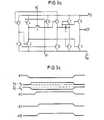
- Fig. 1the usual addressing principle of a known read-write memory z. B. shown using the row lines.
- each of the address lineswhich are inverse to one another in pairs, so that one of the address lines A o or ⁇ o , A, or A 1 , etc. is connected.
- theyare each redundant Row ez i , ez 2 etc. (or column) assigned and controlled by redundancy decoders RD 1 , RD 2 , etc., each controlled by the address lines A o , to Ap, ⁇ p provided per se for normal operation, that the individual redundancy decoder both through all address lines as well as through all the inverted address lines (i.e. A o , A o , A 1 , A 1 ' etc.) is applied.
- the addressing of the matrix with regard to the column linesis done in an analog manner using other address lines and decoders.
- a redundancy decoder RD 1 , RD 2 ?? previously programmed (due to the permanent change)is addressed by a corresponding address combination
- this signalis applied to a dedicated input of each normal decoder ND 1 , ND 2 , etc., so that the normal decoder selected by the address combination created is blocked.
- the addressed redundancy decoderactivates the matrix row or matrix column assigned to it and serving as a replacement.
- each of the row redundancy decoders RD v(or column redundancy decoder) contains a NOR gate, the inputs of which each one of the row address lines A o , ⁇ o .» Ap, ⁇ p (or column address lines) are assigned, the connection F between the individual input and the address line controlling it in each case being designed to be separable.
- 2are those of a first redundant line ez v or ez v and that of a further redundant line eZ v + 1 or ez v + 1 associated redundancy decoder shown and designated with RD v or RD v + 1 .
- each of the redundancy decoders RD vis assigned two AND gates, U v and U v * , each of which has two signal inputs. One of these two signal inputs of both AND gates U v , U v * is located at the output of the NOR gate representing the associated redundancy decoder RD v .
- each individual AND gate U vis applied to each of the row redundancy decoders RD v (or column redundancy decoder) provided at an input of an OR gate OG common to all redundancy decoders, while the other signal input of all AND gates U v is from a common one Clock signal 02 is controlled.
- the other input of each AND gate U v *is controlled by a common activation signal 03R.
- each AND gate U v *enables or closes one by means of a transfer transistor Tr v or T r v given connection between the relevant row redundancy decoder RD v (or column redundancy decoder) respectively assigned redundant row lines ez v , ez v (or column lines) and a data input or data output S / L or S / L common to the row or column.
- the clock signal 02 obtained in the manner just describedis delayed via the series connection of two further inverters I.
- Fig. 2ais the interaction between the individual redundancy decoders RD v and Normal decoders ND ⁇ shown. Any redundancy decoder RD v and any normal decoder ND ⁇ are shown.
- the OR gate OG shown in FIG. 2 and on the input side via the AND gates U v from the entirety of the redundancy decoders RD vis connected with its output signal 0k, called inhibit signal 0k, to an input of an AND gate U ** via an inverter. , at the other input of which is the clock signal 02.
- This AND gate U **which, like the OR gate OG, is assigned to all row redundancy decoders RD v together, controls the one input of m AND gates U ⁇ + , each with two inputs, one of which is connected to the one Output of the AND gate U ** and the other at the output of the AND gate U ⁇ - each assigned normal address decoder ND.
- Each of the m normal decoders ND L provided for normal operationis thus assigned one of these AND gates U ⁇ - which, as can be seen in FIG. 2a, corresponds to the AND gate U v * of the individual redundancy decoders RD v .
- each AND gate U ⁇ +only responds if a «1 is pending at the output of the NOR gate representing the normal decoder ND ⁇ , ie if there is no « 1 at any of the address inputs of the normal decoder ND ⁇ .
- the output of the AND gate U ⁇ +controls to the associated lines nz ⁇ and nz ⁇ , which are intended for normal operation, belonging to the transfer transistors Tr ⁇ or T r ⁇ , which is a release of a connection between these lines nz ⁇ , nz ⁇ , and form a data input or data output S / L, S / L within the memory matrix.
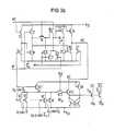
- the embodiment shown in FIG. 3 for the individual redundancy decoders RD v in MOS technologyis essentially the same in effect as that of a redundancy decoder RD v according to FIG. 2. However, it is even better adapted to the operation of a dynamic memory.
- the configurationlike the configuration of the additional circuit parts shown in FIGS. 3a and 3b, is preferably carried out using n-channel MOS technology, in particular if the remaining parts of the memory are also produced using this technology. Agreement is then given with regard to the configuration of the circuit parts forming the individual redundancy decoders.
- each row address line A 0 , A 0 , ?? Ap, ⁇ peach assigned a transistor T, the gate of which forms a signal input of the NOR gate contained in the relevant redundancy decoder RD v .
- the source connections of these transistors Tare common to a reference potential V ss , while their drain connections together form the output A of the NOR gate and are also connected via the source-drain path of a load transistor T1 controlled by a clock signal 01 to a supply connection supplying a supply potential V oo .
- the output A of the NOR gate contained in the respective redundancy decoder RD vlies by means of the source-drain path of a further transistor T2 at a node B, which forms the actual output of the relevant redundancy decoder RD v and which accordingly controls the transfer transistors Tr v and Tr v serves in a manner yet to be described, with this control switching the redundant row lines ez v and ez v associated with the relevant redundancy decoder RD v to the data input or output S / L and S / L.
- each of the redundancy decoders RD v providedhas a further MOS field-effect transistor T3, whose drain terminal is supplied to the clock signal 02, whose gate is placed v to the output B of the associated redundant decoder RD, and whose source terminal is connected through a branch of a first RS flip-flop FF1 to the reference potential V ss.
- RS flip-flop FF1corresponds to the electrical connection of the source connection of the respective transistor T3 to the drain of a first and the gate of a second transistor, which Form flop FF1.
- the two transistors forming the RS flip-flop FF1are cross-coupled in a known manner and, with their source connection, are common to the reference potential V ss .
- the transistor T3Due to the aforementioned connection of the transistor T3 to the one node of the RS flip-flop FF1, the second node of which is connected to the terminal for the supply potential V DD ) via a load transistor R connected as a resistor, the latter is capable of being connected to the to provide the relevant redundancy decoder RD v for the influencing of a normal decoder ND ⁇ to be replaced by the necessary bit signal 0k.
- This inhibit signal 0kis in each case supplied by the node formed by the source of the transistor T3 and the points of the RS flip-flop FF1 connected to it and is applied to one for all these RS flip-flops FF1 and thus for all redundancy decoders RD v common further node C is placed, which corresponds in its function to the OR gate OG in FIGS. 2 and 2a.
- a mareefes RS flip-flop FF2is connected to the sources of its two cross-coupled transistors is also the reference potential V ss and with its one node via a further transistor connected as a resistor R to the supply potential V DD.
- the other node of this RS flip-flop FF2is at the source of a transistor T4 corresponding to transistor T3. This is controlled at its drain by the clock 03R and at its gate by the node B of the associated transistor T2 and thus by the output of the associated redundancy decoder RD v .
- the node formed at the source of transistor T4is in turn connected to the gates of the associated transfer transistors Tr v and T r v placed, whereby the above-mentioned control of these two transfer transistors comes about.
- FIG. 3ashows a MOS circuit which is used to generate the activation signals 03R required for the application of the drain connection of the transistor T4 in FIG. 3 in the provided redundancy decoders RD v and which is adapted to the configuration of the redundancy decoder according to FIG. 3 .
- the clock signal 01 required to apply itis also provided for the normal operation of the memory. However, a signal can also be used which is generated specifically for this purpose by means of a clock generator.
- the clock signal 01is required to log. "0" goes before addresses reach the normal decoders ND ⁇ and the redundancy decoders RD v via the address lines A o .... ⁇ p and before the clock signal 02 reaches log. «1 switches.
- the time behavior of the clock signal 01 with regard to the signals on the address lines A o to Ap or ⁇ o to ⁇ pcan be seen from the time diagram according to FIG. 3c.
- the rising edge of the signals on the address lines A o , A 0 , ..., Ap, ⁇ pis delayed in time compared to the falling edge of clock signal 01, while the rising edge of clock signal 02 lies in time before the rising edge of activation signals 03 and 03R, whose rising edges can come at the same time.
- two transistors 1 and 2together form a first inverter, in which the switching transistor 1 controlled by the clock signal 01 with its source connection at the reference potential V ss and with its drain on the one hand via that of the clock signal 02 Controlled load transistor 2 is connected to the supply potential V DD and on the other hand forms the signal output of the first inverter with its source together with the drain of the transistor 1.
- This signal outputcontrols the switching transistor 3 of a second inverter, the load transistor 4 of which is controlled by the clock signal 01.
- the second inverter 3, 4corresponds entirely to the first inverter 1, 2.
- This inverter formed by a switching point between the two transistors 3 and 4 of the second inverteris a) connected via a transfer transistor 5 controlled by the clock signal 02 to the source of a transistor 12 controlled by the clock signal 01, the drain of which is connected to the supply potential V DD , and also b) by means of the transfer transistor 5 just mentioned to the gate of a further MOS field-effect transistor 6, the drain of which is acted on by the clock signal 02.
- the last-mentioned transistor 6is connected with its source connection on the one hand via the source-drain path of a transistor 10 controlled by the clock signal 01 to the reference potential V SS and also connected to the gates of two further transistors 7 and 8 whose drain connections are at the supply potential V DD .
- transistor 7it should be noted that its gate is connected to its own source terminal via a capacitor C.
- the source terminal of this transistor 7is connected to the reference potential V ss via the drain source path of a further transistor 9.
- the transistor 9is controlled at its gate by the output of the second inverter formed in the manner already described by the two transistors 3 and 4.
- the latteralso applies to a further transistor 11, the source of which is at the reference potential V SS and the drain of which is connected to the supply potential V DD via the transistor 8 already described.
- the clock 0 ⁇ 3R to be generatedcan be removed at a circuit point between the last two transistors 8 and 11.
- a first inverterconsisting of the two transistors 14 and 15, with its switching transistor 14 at the reference potential V ss and with its load transistor 15 at the supply potential V oo , is controlled with respect to its switching transistor 14 by the clock signal 01 and with respect to its load transistor 15 by the clock signal 02.
- the output of the first inverter given by a switching point between these two transistors 14 and 15controls the gate of the switching transistor 16 of a further inverter.
- the switching transistor 16is of the second inverter 17 to its source terminal also at the reference potential V ss, and its drain to the source terminal of the connection to the supply potential V oo forming and controlled by the clock signal 01 the load transistor. Similar to FIG.
- the inverter output given by a circuit point between the transistors 16 and 17is connected to a transfer transistor 18, the gate of which is controlled by the clock signal 02.
- the current-carrying connection of the transfer transistor 18 facing away from the second inverter 16, 17is connected, on the one hand, to the reference potential V ss via a transistor 20, controlled by the inhibit signal 0k supplied by a circuit according to FIG. 3 by the redundancy decoders RD v .
- itlies at the gate of a transistor 19, the drain of which is acted upon by the clock signal 02.
- the source of the last-mentioned transistor 19is connected to the reference potential V ss via the parallel connection of two further transistors 21 and 22, the gate of the transistor 21 being the inhibit signal 0k supplied by the redundancy decoders RD v and the gate of the other transistor 22 being the clock signal 01 is applied. Furthermore, the source of transistor 19 provides a node which is located at the gate of two further transistors 23 and 24 and at one pole of a capacitor C * . The other pole of the capacitor C * is connected to the source terminal of the transistor 23.
- the drain connections of the transistors 23 and 24are at the supply potential V DD and their source connections are each connected via a transistor 25 and 26, controlled by the output of the second inverter 16, 17, to the reference potential V ss .
- connection between the transistor 24 and the reference potential V ss-providing transistoris connected in parallel 26, the source-drain path of a controlled by the inhibit transistor 0k 27th
- the activation signal 03 required for the application of the normal decoder ND ⁇is supplied by a node between the transistors 24, 26 and 27.
- the normal decoder ND ⁇are designed in the manner also evident from FIG. 3b.
- a number p of MOS field effect transistors NT with their source connection at the reference potential V ss and via a common load transistor NT1 at the supply potential V DDform the NOR gate, which is contained in the normal decoder ND ⁇ .
- the gate of each of these transistors NTis assigned one of the address inputs A o or ⁇ o , ...... Ap or ⁇ p provided for activating the normal decoder ND ⁇ .
- the output A 'of the NOR gatethat is the node between the drains of the transistors NT connected in parallel and the source of the load transistor NT1 - controlled by the clock signal 01 - is in turn connected to a transfer transistor NT2, the gate of which is connected to the supply potential V DD and whose other connection leads to the gate of a further transistor NT3.
- the drain terminal of the transistor NT3is acted upon by the activation signal 03 and is therefore connected to the drain of the transistors 26 and 27 and to the source of the transistor 24.
- the source terminal of the transistor NT3is located at a node of a RS flip-flop FF3, whose foot points are to the reference potential V ss and the second node is connected via a load transistor connected as a resistor REF to the supply potential V DD.
- the RS flip-flops FF1 and FF2 in the individual redundancy decoders RD v and the RS flip-flop FF3 in the individual normal decoders ND ⁇serve to ensure the safety of the circuit and could in principle also be replaced by other circuits customary for this purpose.
- the transistor NT3which is acted upon by the activation signal 03 at its drain, forms with its source connection located at the RS flip-flop FF3 the output of the normal decoder ND ⁇ , which in turn is connected to the gates of the transfer transistors Tr ⁇ and Tr ⁇ to be controlled by the normal decoder ND ⁇ the connection of the lines nz ⁇ assigned to the normal decoder ND ⁇ and intended for normal operation nz Form ⁇ (or columns) with the associated data input or data output S / L or S / L.
- the connections Fthat is to say by the permanent modification to any redundancy decoder RD v
- the connections Fcan be used for each redundant row ez v either the transistor T for the address line A i or the transistor T for the address line A i (each time: 1 ⁇ i ⁇ p) are separated from decoder node A and programming of one or more redundancy decoders RD v is achieved in this way.
- redundancy decoders RD v and R v-1are programmed in FIG. 3.
- the advantages of the redundancy concept of the inventionare a lesser compared to the conventional solution space consumption, as the regular decoder ND ⁇ experienced by pasting the redundancy no change (signal SS in Figure 1. saving ⁇ of an input each normal decoder ND. Furthermore, in an advantageous manner a Time saving compared to the redundancy concept shown in FIG. 1 is achieved because suitable dimensioning of the advantageous circuits shown in FIGS. 3, 3a, 3b and also in FIGS. 2 and 2a ensures that the activation signal 03 remains deactivated even when that Inhibit signal 0k only goes high after a delay of approximately 1 ns compared to the rising edge of clock signal 02.
- the proposed redundancy conceptcan also be used if so-called center decoders are to be used as address decoders for addressing the memory cells.
- Theseare cell array arrangements which are divided into a left and a right half of the cell array, in which the address decoder simultaneously selects two pairs of bit lines.
- a bit line pairis spatially arranged on one side (left cell field half), the other on the other side (right cell field half) of the center decoder.
- This means that the center decoderis simultaneously responsible for addressing the corresponding rows in both halves of the entire cell field.
- the linescan e.g. B. can be designed as “folded” bit lines.
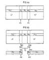
- Fig. 4aThe corresponding, known space allocation scheme is shown in Fig. 4a.
- the cell fieldis divided into a left half LZF and a right half RZF, between which a row of the above-mentioned center decoder MD ⁇ extends.
- these center decoders MD ⁇must act on the left half of the cell array LZF as well as on the right half of the cell array RZF, so that for each center decoder MD ⁇ both a left «switch» LS for addressing in the left half of the cell field LZF and a right «switch »RS ⁇ are provided for addressing in the right half of the cell field RZF.
- redundancy decoder RD vfor the redundancy line halves ez vi ,, ez vi arranged on the left and right, as in FIG. 4b as a redundancy decoder RD vi , RD vr shown.
- the left and right switches LS ⁇ RS ⁇which lie between the center decoders MD ⁇ and the left or right cell field half LZF, RZF, are activated by an activation signal 0 ⁇ 3 1 or 03 r .
- the purpose and design of the two circuits (not shown in the figures ) which generate the activation signals 0 ⁇ 3 1 , 0 ⁇ 3 rare analogous to the circuit part already described in FIG. 3b, which generates the activation signal 03 there.
- a corresponding logic circuit diagramis contained in Fig. 2a.
- an inhibition signal 0k ris used to suppress the activation signal 03 r .
- Both inhibit signals 0 ⁇ k 1 , 0 ⁇ k rare generated in the redundancy decoders RD vr or RD vr , analogously to the circuit according to FIG. 3.
- Both redundancy decoders RD vl , RD vrare identical in terms of circuitry to the redundancy decoders RD v known from FIG. 3.
- eachcorresponds to one line nz ⁇ of that intended for normal operation and in the two halves LZF and RZF divided cell array associated center decoder MD ⁇ functionally and in terms of circuitry of the NOR gate known from FIG. 3b together with the associated load transistor NTI of a normal decoder ND ⁇ .
- the left switch LS ⁇is connected to the center decoder MD ⁇ and the right switch RS ⁇ to the right.
- the connectionis made via a transfer transistor NT2 i , NT2 r , the gate of each transfer transistor NT2 i , NT2 being connected to the supply potential V DD .
- the two transfer transistors NT2 and NT2correspond to the transfer transistor NT2 known from FIG. 3b.
- the transfer transistor NT2is connected at its r the center decoder MD ⁇ remote from the current-carrying terminal connected to the gate of a transistor NT3, and the transfer transistor NT2 r in a corresponding manner to the gate of the transistor NT3.
- the two transistors NT3 and NT3 rcorrespond to the transistor NT3 of the normal decoder ND u shown in FIG. 3b and are accordingly acted upon at their drain connections by an activation signal 03 or ⁇ 3r corresponding to the activation signal 03, the generation of which has already been described.
- the RS flip-flop FF3known from FIG.
- 3bis represented twice - in the form of the RS flip-flop FF3, and the RS flip-flop FF3 r -, the RS flip-flop FF3, in the left switch LS ⁇ and the RS flip-flop FF3 r are contained in the right switch RS ⁇ .
- the inventionis applicable to both static and dynamic random access memories.
- itis also applicable to dynamic random access memories whose memory cells are constructed as one-transistor memory cells.
Landscapes
- For Increasing The Reliability Of Semiconductor Memories (AREA)
- Techniques For Improving Reliability Of Storages (AREA)
- Static Random-Access Memory (AREA)
- Memory System Of A Hierarchy Structure (AREA)
Abstract
Description
Translated fromGermanGegenstand der vorliegenden Erfindung ist ein integrierter Schreib-Lesespeicher nach dem Oberbegriff des Patentanspruches 1.The present invention relates to an integrated read-write memory according to the preamble of
Schreib-Lesespeicher der o. g. Art sind allgemein bekannt und z. B. in « 1981 IEEE International Solid-State Circuits Conference », S. 80, 81, 84 und 85 beschrieben. Dort handelt es sich um dynamische Schreib-Lesespeicher, deren einzelne Speicherzellen als Ein-Transistor-Speicherzeilen ausgebildet sind.Read-write memory of the above Kind are generally known and z. B. described in "1981 IEEE International Solid-State Circuits Conference", pp. 80, 81, 84 and 85. There are dynamic read-write memories, the individual memory cells of which are designed as one-transistor memory rows.
Entsprechende Schreib-Lesespeicher, insbesondere solche mit Aktivierung von Dekodern, sind auch aus «Japanese Journal of Applied Physics. Supplements, vol. 22 (1983) suppl. n° 22-1, Tokyo, Japan •, Seiten 63 bis 67, « Redundancy Techniques for Dynamic RAMS » bekannt.Corresponding read / write memories, in particular those with activation of decoders, are also from «Japanese Journal of Applied Physics. Supplements, vol. 22 (1983) suppl. n ° 22-1, Tokyo, Japan •, pages 63 to 67, “Redundancy Techniques for Dynamic RAMS”.
Bei mit Redundanz ausgestatteten Schreib-Lesespeichern ist die Möglichkeit gegeben, zu defekten Speicherzellen führende Spalten bzw. Zeilenleitungen der Speichermatrix elektrisch zu deaktivieren, d. h. funktionsunfähig zu machen und dafür eine identische redundante Matrixleitung zu aktivieren. Dies geschieht in der Regel durch Auftrennen von leitenden Verbindungen (fusible link), die den der redundanten Matrixleitung zugehörigen Adreßdekoder (Redundanzdekoder) im zunächst nicht aufgetrennten Zustand als nicht ausgewählt erscheinen läßt. Durch das Auftrennen wird infolge entsprechender Ausgestaltung des der redundanten Matrixleitung zugehörigen Redundanzdekoders in dem für den Normalbetrieb vorgesehenen Teil der Speichermatrix erreicht, daß aufgrund der Adressierung der ersetzten Spalte oder Zeile nur die nunmehr aktivierte entsprechende redundante Matrixleitung anspricht. Auf welche Art man dies in üblicher Weise erreicht, wird im folgenden anhand der Fig. 1 erläutert.In the case of read / write memories equipped with redundancy, there is the possibility of electrically deactivating columns or row lines of the memory matrix leading to defective memory cells; H. to make it inoperable and to activate an identical redundant matrix line. This is usually done by separating conductive connections (fusible link), which makes the address decoder (redundancy decoder) associated with the redundant matrix line appear unselected in the state that was initially not separated. As a result of the corresponding design of the redundancy decoder associated with the redundant matrix line in the part of the memory matrix provided for normal operation, the separation means that only the now activated corresponding redundant matrix line responds due to the addressing of the replaced column or row. The way in which this is achieved in the usual way is explained below with reference to FIG. 1.
Es ist verständlich, daß der für die Deaktivierung der defekten Matrixleitung und der Aktivierung der Ersatzleitung erforderliche Aufwand an Schaltungsmaßnahmen und damit an Chipfläche möglichst gering sein soll. Außerdem ist es erwünscht, daß diese Maßnahmen mit einer möglichst geringen Zeitverzögerung beim Betrieb des Speichers verbunden sind. Schließlich soll der Betrieb des Speichers keine Einbuße an Verläßlichkeit erleiden.It is understandable that the effort required for the deactivation of the defective matrix line and the activation of the replacement line in circuit measures and thus in chip area should be as low as possible. In addition, it is desirable that these measures are associated with the least possible time delay in the operation of the memory. After all, the operation of the storage facility should not suffer any loss of reliability.
Es ist deshalb Aufgabe der vorliegenden Erfindung, den bekannten Schreib-Lesespeicher derart weiterzubilden, daß diesen Forderungen Rechnung getragen wird, ohne daß dies mit störenden Nachteilen verbunden ist.It is therefore an object of the present invention to develop the known read-write memory in such a way that these requirements are taken into account without this being associated with disruptive disadvantages.
Diese Aufgabe wird bei einem integrierten Schreib-Lesespeicher der eingangs genannten Art durch die Merkmale des kennzeichnenden Teiles des Patentanspruches 1 gelöst.This object is achieved in an integrated random access memory of the type mentioned by the features of the characterizing part of
Vorteilhafte Weiterbildungen der Erfindung sind in jeweiligen Unteransprüchen gekennzeichnet.Advantageous developments of the invention are characterized in the respective subclaims.
Im folgenden wird nun die Erfindung anhand der Figuren 1 bis 5 näher erläutert.The invention is now explained in more detail below with reference to FIGS. 1 to 5.
Es zeigen :
- Fig. 1 das Redundanzprinzip nach dem Stande der Technik,
- Fig. 2 die erfindungsgemäße Verschaltung von Redundanzdekodern mit den zugehörigen Schreib-Leseleitungen der redundanten Zeilen und die Erzeugung zugehöriger Taktsignale, unter Verwendung von Logiksymbolen,
- Fig. 2a die erfindungsgemäße Verknüpfung eines Schaltungsteiles zur Auswahl einer redundanten Zeile mit einem Schaltungsteil zur Auswahl einer für den Normalbetrieb vorgesehenen Zeile, jeweils mit Logiksymbolen dargestellt,
- Fig. 3 die Realisierung der Schaltung nach Fig. 2 mittels MOS-Transistoren,
- Fig. 3a die erfindungsgemäße Erzeugung eines Aktivierungssignales ß3R,
- Fig. 3b die erfindungsgemäße Erzeugung eines
Aktivierungssignales 03 und dessen vorteilhafte Verschaltung mit einem Normaldekoder, - Fig. 3c ein Zeitdiagramm für die verwendeten Taktsignale,
- Fig. 4a eine schematische Darstellung eines bekannten Schreib-Lesespeichers mit Mittendekoder,
- Fig. 4b eine schematische Darstellung eines erfindungsgemäßen Schreib-Lesespeichers mit Mittendekoder und redundantem Speicherbereich,
- Fig. 5 einen Schaltplan zur erfindungsgemäßen Ausgestaltung von Mittendekodern und Schaltern.
- 1 shows the redundancy principle according to the prior art,
- 2 the interconnection of redundancy decoders according to the invention with the associated read / write lines of the redundant lines and the generation of associated clock signals using logic symbols,
- 2a shows the connection according to the invention of a circuit part for selecting a redundant line with a circuit part for selecting a line intended for normal operation, each represented with logic symbols,
- 3 the realization of the circuit according to FIG. 2 by means of MOS transistors,
- 3a the generation of an activation signal β3R according to the invention,
- 3b the generation of an
activation signal 03 according to the invention and its advantageous interconnection with a normal decoder, - 3c is a timing diagram for the clock signals used,
- 4a is a schematic representation of a known read-write memory with center decoder,
- 4b is a schematic representation of a read-write memory according to the invention with center decoder and redundant memory area,
- Fig. 5 is a circuit diagram for the inventive design of center decoders and switches.
Bezüglich der Bezugszeichen wurde folgende Konvention getroffen :
- der verwendete Index « µ » hat einen Wertebereich von 1 bis m (m = Gesamtzahl der für den Normalbetrieb vorgesehenen Zeilen),
- der Index « v einen Wertebereich von 1 bis n (n = Gesamtzahl der für den Redundanzfall vorgesehenen Ersatzzeilen) ; « 1 wird bei Bezeichnungen verwendet, die eine linke Zellenfeldhälfte betreffen,
- « r » entsprechend für eine rechte Zellenfeldhälfte,
- « p » steht für die Gesamtzahl von Adreßleitungen (ohne komplementäre Adreßleitungen).
- the index “µ” used has a value range from 1 to m (m = total number of lines intended for normal operation),
- the index «v a value range from 1 to n (n = total number of replacement lines intended for the redundancy case); «1 is used in terms that refer to a left half of the cell field,
- Correspondingly for a right half of the cell field,
- «P» stands for the total number of address lines (without complementary address lines).
In Fig. 1 ist das übliche Adressierprinzip eines bekannten Schreib-Lesespeichers z. B. anhand der Zeilenleitungen gezeigt. Die Normaldekoder ND1, ND2, ....... dienen der Adressierung der dem Normalbetrieb zugeordneten Normalzeilen nzi, nz2, ....., während die Dekoder RD1, RD2 neben möglichen weiteren Dekodern als Redundanzdekoder für die Beaufschlagung von in der Matrix vorgesehenen redundanten Zeilen ez1, eZ2 usw. vorgesehen sind. Es ist aus Fig. 1 ersichtlich, daß jeder Normaldekoder ND1, ND2 usw. an jedem Eingang von jeweils einer der paarweise zueinander inversen Adreßleitungen beaufschlagt wird, so daß immer eine der Adreßleitungen Ao oder Äo, A, oder A1, usw. angeschlossen ist. Im Gegensatz hierzu sind die jeweils einer redundanten Zeile ezi, ez2 usw. (bzw. Spalte) zugeordneten und durch je ein NOR-Gatter gegebenen Redundanzdekoder RD1, RD2, usw. derart durch die an sich für den Normalbetrieb vorgesehenen Adreßleitungen Ao, bis Ap, Äp gesteuert, daß der einzelne Redundanzdekoder sowohl durch alle Adressleitungen als auch durch alle hierzu invertierten Adreßleitungen (also Ao,
Es soll aber dann aufgrund der genannten bleibenden Änderung nur der durch diese Änderung aktivierte Redundanzdekoder ansprechen. Aus diesem Grund sind die Ausgänge aller vorgesehenen und einander gleichen Redundanzdekoder-NOR-Gatter RD1, RD2 usw. jeweils an je einen Eingang eines gemeinsamen weiteren NOR-Gatters N angeschlossen, dessen Ausgang über einen Inverter I an je einen weiteren Eingang aller der für den Normalbetrieb vorgesehenen Adreßdekoder ND1, ND2 usw. angeschlossen ist. Ist nun einer der Redundanzdekoder RD1, RD2...... aktiviert und damit durch die an den Adreßleitungen Ao,
Die Adressierung der Matrix hinsichtlich der Spaltenleitungen geschieht unter Verwendung anderer Adreßleitungen und Dekoder auf analoge Art.The addressing of the matrix with regard to the column lines is done in an analog manner using other address lines and decoders.
Wird bei einer Ausgestaltung der Adressierung entsprechend. Fig. 1 ein vorher (aufgrund der bleibenden Änderung) programmierter Redundanzdekoder RD1, RD2..... durch eine entsprechende Adreßkombination angesprochen, so wird durch diesen ausgewählten Redundanzdekoder RD1, RD2.... ein Sperrsignal SS = High (=logisch « 1 » ) erzeugt. Dieses Signal wird zusätzlich zu den Adressen an einen eigens hierfür vorgesehenen Eingang eines jeden Normaldekoders ND1, ND2 usw. gelegt, sodaß der durch die angelegte Adreßkombination ausgewählte Normaldekoder gesperrt wird. Andererseits aktiviert der angesprochene Redundanzdekoder die ihm jeweils zugeordnete und dem Ersatz dienende Matrixzeile bzw. Matrixspalte.If the addressing is configured accordingly. 1 a redundancy decoder RD1 , RD2 ..... previously programmed (due to the permanent change) is addressed by a corresponding address combination, a blocking signal SS = High () is selected by this selected redundancy decoder RD1 , RD2 ... = logical «1»). In addition to the addresses, this signal is applied to a dedicated input of each normal decoder ND1 , ND2 , etc., so that the normal decoder selected by the address combination created is blocked. On the other hand, the addressed redundancy decoder activates the matrix row or matrix column assigned to it and serving as a replacement.
Bei einem erfindungsgemäßen Schreib-Lesespeicher enthält nach Fig. 2 jeder der Zeilenredundanzdekoder RDv (bzw. Spaltenredundanzdekoder) ein NOR-Gatter, dessen Eingängen jeweils eine der insgesamt vorgesehenen, zueinander paarweise inversen Zeilenadressleitungen Ao, Äo....... Ap, Äp (bzw. Spaltenadreßleitungen) zugeordnet sind, wobei die Verbindung F zwischen dem einzelnen Eingang und der ihn jeweils steuernden Adreßleitung auftrennbar ausgestaltet ist. In Fig. 2 sind der einer ersten redundanten Zeile ezv bzw.
Die Erzeugung des Taktsignales 02 bzw. des Aktivierungssignales 03R (R = Redundanz) geschieht z. B. in der aus Fig. 2 ersichtlichen Weise, indem ein für den Betrieb aller Redundanzdekoder RDv der Speicherschaltung gemeinsam vorgegebenes Taktsignal 01 über eine Kette aus drei einander gleichen und hintereinandergeschalteten Invertern I zur Erzeugung des zur Mitsteuerung der UND-Gatter Uv vorgesehenen Taktsignales 02 dient. Zwecks Erzeugung des zur Mitsteuerung der UND-Gatter Uv* benötigten Aktivierungssignales 03R wird das auf die soeben beschriebene Weise erhaltene Taktsignal 02 über die Serienschaltung zweier weiterer Inverter I verzögert.The generation of the
In Fig. 2a ist nun das Zusammenspiel zwischen den einzelnen Redundanzdekodern RDv und den Normaldekodern NDµ gezeigt. Es sind ein beliebiger Redundanzdekoder RDv und ein beliebiger Normaldekoder NDµ dargestellt. Das aus Fig. 2 ersichtliche und eingangsseitig über die UND-Gatter Uv von der Gesamtheit der Redundanzdekoder RDv beaufschlagte ODER-Gatter OG liegt mit seinem Ausgangssignal 0k, genannt Inhibitsignal 0k, über einen Inverter am einen Eingang eines UND-Gatters U**, an dessen anderem Eingang das Taktsignal 02 liegt. Der Ausgang dieses UND-Gatters U**, das ebenso wie das ODER-Gatter OG allen Zeilenredundanzdekodern RDv gemeinsam zugeordnet ist, steuert den einen Eingang von m UND-Gattern Uµ+ mit jeweils zwei Eingängen, von denen der eine jeweils an dem Ausgang des UND-Gatters U** und der andere an dem Ausgang des dem UND-Gatter Uµ- jeweils zugeordneten Normaladreßdekoders ND, liegt. Jedem der m für den Normalbetrieb vorgesehenen Normaldekoder NDL ist somit jeweils eines dieser UND-Gatter Uµ- zugeordnet, das, wie aus Fig. 2a hervorgeht, dem UND-Gatter Uv* der einzelnen Redundanzdekoder RDv entspricht. Es wird dementsprechend an seinem anderen Eingang durch ein dem Aktivierungssignal 03R entsprechendes Aktivierungssignal 03 gesteuert. Dieses Aktivierungssignal 03 wird vom Ausgang des UND-Gatters U** geliefert. Jedes UND-Gatter Uµ+ spricht aber nur dann an, wenn am Ausgang des den Normaldekoder NDµ darstellenden NOR-Gatters eine « 1 anhängig ist, d. h. wenn an keinem der Adreßeingänge des Normaldekoders NDµ eine « 1 liegt. Der Ausgang des UND-Gatters Uµ+ steuert zu den zugehörigen Zeilen nzµ und
Hinsichtlich der Wirkung der in Fig. 2 bzw. 2a dargestellten Schaltung gemäß der Erfindung läßt sich nun folgendes feststellen : Da die in Fig. 2a gezeigte Schaltung für den Normaldekoder NDµ in getakteten Schreib-Lesespeichern allgemein angewendet wird und demgemäß das UND-Gatter Uw- zum Zwecke der Verbindung der ausgewählten Zeilen nzµ und
Die in Fig. 3 dargestellte Ausgestaltung für die einzelnen Redundanzdekoder RDv in MOS-Technik ist in der Wirkung der eines Redundanzdekoders RDv entsprechend Fig. 2 im wesentlichen gleich. Sie ist jedoch dem Betrieb eines dynamischen Speichers noch besser angepaßt. Bevorzugt erfolgt die Ausgestaltung - ebenso wie die Ausgestaltung der in Fig. 3a und 3b gezeigten ergänzenden Schaltungsteile - in n-Kanal-MOS-Technik, insbesondere wenn auch die übrigen Teile des Speichers in dieser Technik hergestellt sind. Hinsichtlich der Ausgestaltung der die einzelnen Redundanzdekoder bildenden Schaltungsteile ist dann Übereinstimmung gegeben.The embodiment shown in FIG. 3 for the individual redundancy decoders RDv in MOS technology is essentially the same in effect as that of a redundancy decoder RDv according to FIG. 2. However, it is even better adapted to the operation of a dynamic memory. The configuration, like the configuration of the additional circuit parts shown in FIGS. 3a and 3b, is preferably carried out using n-channel MOS technology, in particular if the remaining parts of the memory are also produced using this technology. Agreement is then given with regard to the configuration of the circuit parts forming the individual redundancy decoders.
Wie bei den in Fig. 3 dargestellten Redundanzdekodern RDv und RDv±1 ersichtlich, ist jeder Zeilenadreßleitung A0,
Zur Erzeugung des aus Fig. 2 bzw. 2a ersichtlichen Inhibitsignales 0̸k, das dort von dem ODER-Gatter OG geliefert wird, hat man im Falle der Redundanzdekoder RDv gemäß Fig. 3 bei jedem der vorgesehenen Redundanzdekoder RDv je einen weiteren MOS-Feldeffekttransistor T3, dessen Drainanschluß vom Taktsignal 02 beaufschlagt ist, dessen Gate an den Ausgang B des zugehörigen Redundanzdekoders RDv gelegt ist, und dessen Sourceanschluß über den einen Zweig eines ersten RS-Flip-Flops FF1 mit dem Bezugspotential Vss verbunden ist. Das vom Taktsignal 02 gesteuerte UND-Gatter Uv in Fig. 2 bzw. 2a entspricht in Fig. 3 der elektrischen Verbindung des Sourceanschlusses des jeweiligen Transistors T3 mit dem Drain eines ersten und dem Gate eines zweiten Transistors, die das genannte RS-Flip-Flop FF1 bilden. Die beiden das RS-Flip-Flop FF1 bildenden Transistoren sind in bekannter Weise kreuzgekoppelt und liegen mit ihrem Sourceanschluß gemeinsam am Bezugspotential Vss. Aufgrund der genannten Anschaltung des Transistors T3 an den einen Knoten des RS-Flip-Flops FF1, dessen zweiter Knoten über einen als Widerstand geschalteten Lasttransistor R mit der Klemme für das Versorgungspotential VDD) verbunden ist, ist dieser in der Lage, das von dem betreffenden Redundanzdekoder RDv für die Beeinflussung eines von ihm zu ersetzenden Normaldekoders NDµ notwendige Inhitbitsignal 0k zur Verfügung zu stellen. Dieses Inhibitsignal 0k wird jeweils durch den von der Source des Transistors T3 und dem aus den mit ihr verbundenen Stellen des RS-Flip-Flops FF1 gebildeten Knoten geliefert und auf einen für alle diese RS-Flip- Flops FF1 und damit für alle Redundanzdekoder RDv gemeinsamen weiteren Knoten C gelegt, der in seiner Funktion dem ODER-Gatter OG in den Fig. 2 und 2a entspricht.To generate the inhibit signal 0̸k shown in FIGS. 2 and 2a, which is supplied there by the OR gate OG, in the case of the redundancy decoder RDv according to FIG. 3, each of the redundancy decoders RDv provided has a further MOS field-effect transistor T3, whose drain terminal is supplied to the
Ein weitefes RS-Flip-Flop FF2 liegt mit den Sourceanschlüssen seiner beiden kreuzgekoppelten Transistoren ebenfalls am Bezugspotential Vss und mit seinem einen Knoten über einen weiteren als Widerstand geschalteten Transistor R am Versorgungspotential VDD. Der andere Knoten dieses RS-Flip-Flops FF2 liegt am Sourceanschluß eines dem Transistor T3 entsprechenden Transistors T4. Dieser wird an seinem Drain durch den Takt 03R und an seinem Gate durch den Knoten B des zugehörigen Transistors T2 und damit durch den Ausgang des zugehörigen Redundanzdekoders RDv gesteuert. Der am Sourceanschluß des Transistors T4 gebildete Knoten ist seinerseits an die Gates der zugehörigen Transfertransistoren Trv und
Man kann also, wie aus Fig. 3 ersichtlich, bei der dort gezeigten Ausgestaltung der Redundanzdekoder RDv auf eine explizite Realisierung des ODER-Gatters OG in Fig. 2 verzichten, da der Knoten C, der von den das Inhibitsignal 0k liefernden Kombinationen Transistor T3 und RS-Flip- Flop FF1 der Redundanzdekoder RDv gemeinsam beaufschlagt wird, ersichtlich im Verhalten dem Ausgang des ODER-Gatters OG entspricht. Zu erwähnen ist noch, daß die verwendeten Transistoren in der Schaltung gemäß Fig. 3, ebenso auch in Fig. 3a und 3b sämtlich selbstsperrend und vom gleichen Kanaltyp, insbesondere vom n-Kanaltyp, sind.As can be seen from FIG. 3, in the embodiment of the redundancy decoder RDv shown there, an explicit implementation of the OR gate OG in FIG. 2 can be dispensed with, since the node C, the transistor T3 which supplies the inhibit signal 0k, is combined and RS flip-flop FF1, the redundancy decoder RDv is acted upon together, evidently the behavior corresponds to the output of the OR gate OG. It should also be mentioned that the transistors used in the circuit according to FIG. 3, likewise also in FIGS. 3a and 3b, are all self-blocking and of the same channel type, in particular of the n-channel type.
In Fig. 3a ist eine MOS-Schaltung gezeigt, die zur Erzeugung des für die Beaufschlagung des Drainanschlusses des Transistors T4 in Fig. 3 in den vorgesehenen Redundanzdekodern RDv benötigten Aktivierungssignales 03R dient und die an die Ausgestaltung der Redundanzdekoder gemäß Fig. 3 angepaßt ist. Das zu ihrer Beaufschlagung benötigte Taktsignal 01 ist auch für den normalen Betrieb des Speichers vorgesehen. Es kann aber auch ein Signal verwendet werden, das eigens zu diesem Zweck mittels eines Taktgenerators erzeugt wird. Verlangt wird von dem Taktsignal 01, daß es auf log. « 0 » geht, bevor Adressen über die Adressleitungen Ao....Äp an die Normaldekoder NDµ und an die Redundanzdekoder RDv gelangen und bevor das Taktsignal 02 auf log. « 1 schaltet.3a shows a MOS circuit which is used to generate the activation signals 03R required for the application of the drain connection of the transistor T4 in FIG. 3 in the provided redundancy decoders RDv and which is adapted to the configuration of the redundancy decoder according to FIG. 3 . The
Das Zeitverhalten des Taktsignales 01 im Hinblick auf die Signale an den Adreßleitungen Ao bis Ap bzw. Äo bis Äp ist aus dem Zeitdiagramm gemäß Fig. 3c zu ersehen. Die ansteigende Flanke der Signale an den Adreßleitungen Ao,
Bei der in Fig. 3a dargestellten Schaltung zur Erzeugung des Aktivierungssignales 03R bilden zwei Transistoren 1 und 2 zusammen einen ersten Inverter, bei dem der vom Taktsignal 01 gesteuerte Schalttransistor 1 mit seinem Sourceanschluß am Bezugspotential Vss und mit seinem Drain einerseits über den vom Taktsignal 02 gesteuerten Lasttransistor 2 mit dem Versorgungspotential VDD verbunden ist und andererseits mit seiner Source zusammen mit dem Drain des Transistors 1 den Signalausgang des ersten Inverters bildet.In the circuit shown in FIG. 3a for generating the activation signal 03R, two
Dieser Signalausgang steuert den Schaittransistor 3 eines zweiten Inverters, dessen Lasttransistor 4 vom Taktsignal 01 gesteuert ist. Hinsichtlich der Anschaltung an das Bezugspotential Vss und das Versorgungspotential VDD entspricht der zweite Inverter 3, 4 völlig dem ersten Inverter 1, 2.This signal output controls the switching
Der durch einen Schaltungspunkt zwischen den beiden Transistoren 3 und 4 des zweiten Inverters gebildete Ausgang dieses Inverters ist a) über einen vom Taktsignal 02 gesteuerten Transfertransistor 5 an die Source eines vom Taktsignal 01 gesteuerten Transistors 12 geschaltet, dessen Drain mit dem Versorgungspotential VDD verbunden ist, und außerdem b) vermittels des soeben genannten Transfertransistors 5 an das Gate eines weiteren MOS-Feldeffekttransistors 6 gelegt, dessen Drain vom Taktsignal 02 beaufschlagt ist.The output of this inverter formed by a switching point between the two
Der zuletzt genannte Transistor 6 ist mit seinem Sourceanschluß einerseits über die Source-Drainstrecke eines vom Taktsignal 01 gesteuerten Transistors 10 an das Bezugspotential Vss gelegt und außerdem mit den Gates zweier weiterer Transistoren 7 und 8 verbunden, deren Drainanschlüsse am Versorgungspotential VDD liegen. Bei dem Transistor 7 ist dabei zu bemerken, daß dessen Gate über einen Kondensator C mit dem eigenen Sourceanschluß verbunden ist. Außerdem ist der Sourceanschluß dieses Transistors 7 über die Drain-Sourcestrecke eines weiteren Transistors 9 mit dem Bezugspotential Vss verbunden. Weiterhin ist dabei der Transistor 9 an seinem Gate vom Ausgang des in bereits beschriebener Weise von den beiden Transistoren 3 und 4 gebildeten zweiten Inverters gesteuert. Das letztere gilt auch für einen weiteren Transistor 11, dessen Source am Bezugspotential Vss liegt und dessen Drain über den bereits beschriebenen Transistor 8 mit dem Versorgungspotential VDD verbunden ist. Der zu erzeugende Takt 0̸3R ist an einem Schaltungspunkt zwischen den beiden zuletzt genannten Transistoren 8 und 11 abnehmbar.The last-mentioned transistor 6 is connected with its source connection on the one hand via the source-drain path of a
Die Schaltung für die Erzeugung des für die Normaldekoder NDµ benötigten Aktivierungssignales 03 ist in Kombination mit der Schaltung eines beliebigen Normaldekoders NDµ in Fig. 3b gezeigt, die nun beschrieben werden soll.The circuit for generating the
Ein aus den beiden Transistoren 14 und 15 bestehender, mit seinem Schalttransistor 14 am Bezugspotential Vss und mit seinem Lasttransistor 15 am Versorgungspotential Voo liegender erster Inverter ist bezüglich seines Schalttransistors 14 vom Taktsignal 01 und bezüglich seines Lasttransistors 15 durch das Taktsignal 02 gesteuert. Der durch einen Schaltungspunkt zwischen diesen beiden Transistoren 14 und 15 gegebene Ausgang des ersten Inverters steuert das Gate des Schalttransistors 16 eines weiteren Inverters. Dabei liegt der Schalttransistor 16 mit seinem Sourceanschluß ebenfalls am Bezugspotential Vss und mit seinem Drain am Sourceanschluß des die Verbindung zum Versorgungs- potential Voo bildenden und vom Taktsignal 01 gesteuerten Lasttransistors 17 des zweiten Inverters. Ähnlich wie bei Fig. 3a ist der durch einen Schaltungspunkt zwischen dem Transistor 16 und 17 gegebene Inverterausgang an einen Transfertransistor 18 gelegt, dessen Gate vom Taktsignal 02 gesteuert ist. Der dem zweiten Inverter 16, 17 abgewandte stromführende Anschluß des Transfertransistors 18 liegt einerseits über einen - von dem von einer Schaltung gemäß Fig. 3 von den Redundanzdekodern RDv gelieferten Inhibit- signal 0k gesteuerten - Transistor 20 am Bezugspotential Vss. Andererseits liegt er am Gate eines Transistors 19, dessen Drain durch das Taktsignal 02 beaufschlagt ist.A first inverter consisting of the two
Mit seiner Source ist der zuletzt genannte Transistor 19 über die Parallelschaltung zweier weiterer Transistoren 21 und 22 mit dem Bezugspotential Vss verbunden, wobei das Gate des Transistors 21 von dem von den Redundanzdekodern RDv gelieferten Inhibitsignal 0k und das Gate des anderen Transistors 22 vom Taktsignal 01 beaufschlagt ist. Ferner ist durch die Source des Transistors 19 ein Knoten gegeben, der am Gate zweier weiterer Transistoren 23 und 24 sowie am einen Pol eines Kondensators C* liegt. Der andere Pol des Kondensators C* ist mit dem Sourceanschluß des Transistors 23 verbunden. Die Drainanschlüsse der Transistoren 23 und 24 liegen am Versorgungspotential VDD und ihre Sourceanschlüsse über je einen vom Ausgang des zweiten Inverters 16, 17 gesteuerten Transistor 25 bzw. 26 am Bezugspotential Vss. Dabei ist dem die Verbindung zwischen dem Transistor 24 und dem Bezugspotential Vss bildenden Transistor 26 die Source-Drainstrecke eines durch das Inhibitsignal 0k gesteuerten Transistors 27 parallel geschaltet. Das für die Beaufschlagung der Normaldekoder NDµ erforderliche Aktivierungssignal 03 wird von einem Knoten zwischen den Transistoren 24, 26 und 27 geliefert.The source of the last-mentioned
Die Normaldekoder NDµ sind in der ebenfalls aus Fig. 3b ersichtlichen Weise gestaltet. Eine Anzahl p von mit ihrem Sourceanschluß am Bezugspotential Vss und über einen gemeinsamen Lasttransistor NT1 am Versorgungspotential VDD liegender MOS-Feldeffekttransistoren NT bilden das NOR-Gatter, das im Normaldekoder NDµ enthalten ist. Dem Gate jedes dieser Transistoren NT ist je ein der zur Aktivierung des Normaldekoders NDµ vorgesehener Adreßeingang Ao oder Äo, ...... Ap oder Äp jeweils zugeordnet. Der Ausgang A' des NOR-Gatters, also der Knoten zwischen den Drains der parallel geschalteten Transistoren NT und der Source des - vom Taktsignal 01 gesteuerten - Lasttransistors NT1, ist wiederum an einen Transfertransistor NT2 gelegt, dessen Gate mit dem Versorgungspotential VDD verbunden ist und dessen anderer Anschluß zum Gate eines weiteren Transistors NT3 führt. Der Drainanschluß des Transistors NT3 ist vom Aktivierungssignal 03 beaufschlagt und ist deshalb mit dem Drain der Transistoren 26 und 27 sowie mit der Source des Transistors 24 verbunden. Der Sourceanschluß des Transistors NT3 liegt am einen Knoten eines RS- Flip-Flops FF3, dessen Fußpunkte am Bezugspotential Vss liegen und dessen zweiter Knoten über einen als Widerstand geschalteten Lasttransistor NR mit dem Versorgungspotential VDD verbunden ist.The normal decoder NDμ are designed in the manner also evident from FIG. 3b. A number p of MOS field effect transistors NT with their source connection at the reference potential Vss and via a common load transistor NT1 at the supply potential VDD form the NOR gate, which is contained in the normal decoder NDµ. The gate of each of these transistors NT is assigned one of the address inputs Ao or Äo , ...... Ap or Äp provided for activating the normal decoder NDµ . The output A 'of the NOR gate, that is the node between the drains of the transistors NT connected in parallel and the source of the load transistor NT1 - controlled by the clock signal 01 - is in turn connected to a transfer transistor NT2, the gate of which is connected to the supply potential VDD and whose other connection leads to the gate of a further transistor NT3. The drain terminal of the transistor NT3 is acted upon by the
Die RS-Flip-Flops FF1 und FF2 bei den einzelnen Redundanzdekodern RDv und das RS-Flip- Flop FF3 bei den einzelnen Normaldekodern NDµ dienen der Sicherheit der Schaltung und könnten im Prinzip auch durch andere zu diesem Zweck übliche Schaltungen ersetzt werden. Der an dem vom Aktivierungssignal 03 an seinem Drain beaufschlagte Transistor NT3 bildet mit seinem am RS-Flip-Flop FF3 liegenden Sourceanschluß den Ausgang des Normaldekoders NDµ, der mit den Gates der von dem Normaldekoder NDµ zu steuernden Transfertransistoren Trµ und Trµ verbunden ist, die ihrerseits die Verbindung der dem Normaldekoder NDµ zugeordneten und für den Normalbetrieb vorgesehenen Zeilen nzµ und
Es kann nun im Zusammenhang mit den Figuren 3, 3a, 3b und 3c folgendes Verhalten der erfindungsgemäßen Schaltung gezeigt werden : Durch Auftrennen, beispielsweise mit Hilfe von Laserstrahlen, der Verbindungen F (also durch die bleibende Abänderung an einem beliebigen Redundanzdekoder RDv) kann für jede redundante Zeile ezv entweder der Transistor T für die Adreßleitung Ai oder der Transistor T für die Adreßleitung
Die Vorteile des erfindungsgemäßen Redundanzkonzepts sind ein im Vergleich zu der üblichen Lösung geringerer Platzverbrauch, da die regulären Dekoder NDµ durch das Einfugen der Redundanz keine Änderung erfahren (Signal SS in Fig 1. Einsparen eines Eingangs je Normaldekoder NDµ. Außerdem wird auf vorteilhafte Weise eine Zeitersparnis gegenüber dem in Fig. 1 gezeigten Redundanzkonzept erreicht, weil durch geeignete Dimensionierung der in den Figuren 3, 3a, 3b und auch der in den Figuren 2 und 2a dargestellten vorteilhaften Schaltungen gewährleistet ist, daß das Aktivierungssignal 03 auch dann deaktiviert bleibt, wenn das Inhibitsignal 0k erst nach einer etwa 1 ns betragenden Verzögerung gegenüber der Anstiegsflanke des Taktsignales 02 auf « high geht.The advantages of the redundancy concept of the invention are a lesser compared to the conventional solution space consumption, as the regular decoder NDμ experienced by pasting the redundancy no change (signal SS in Figure 1. savingμ of an input each normal decoder ND. Furthermore, in an advantageous manner a Time saving compared to the redundancy concept shown in FIG. 1 is achieved because suitable dimensioning of the advantageous circuits shown in FIGS. 3, 3a, 3b and also in FIGS. 2 and 2a ensures that the
Das vorgeschlagene Redundanzkonzept ist erfindungsgemäß auch dann anwendbar, wenn für die Adressierung der Speicherzellen als Adreßdekoder sog. Mittendekoder verwendet werden sollen. Hierbei handelt es sich um Zellenfeldanordnungen, die in eine linke und eine rechte Zellenfeldhälfte aufgeteilt sind, bei denen der Adreßdekoder gleichzeitig zwei Bitleitungspaare auswählt. Eine Bitleitungspaar ist räumlich auf der einen Seite (linke Zellenfeldhälfte), das andere auf der anderen Seite (rechte Zellenfeldhälfte) des Mittendekoders angeordnet. Dies bedeutet, daß der Mittendekoder gleichzeitig zur Adressierung der entsprechenden Zeilen in beiden Hälften des gesamten Zellenfeldes zuständig ist. Die Zeilen können z. B. als « folded » Bitleitungen ausgeführt sein.According to the invention, the proposed redundancy concept can also be used if so-called center decoders are to be used as address decoders for addressing the memory cells. These are cell array arrangements which are divided into a left and a right half of the cell array, in which the address decoder simultaneously selects two pairs of bit lines. A bit line pair is spatially arranged on one side (left cell field half), the other on the other side (right cell field half) of the center decoder. This means that the center decoder is simultaneously responsible for addressing the corresponding rows in both halves of the entire cell field. The lines can e.g. B. can be designed as “folded” bit lines.
Das entsprechende, bekannte Platzaufteilungsschema ist in Fig. 4a gezeigt. Hier ist das Zellenfeld in eine linke Hälfte LZF und eine rechte Hälfte RZF unterteilt, zwischen denen sich eine Reihe der genannten Mittendekoder MDµ erstreckt. Diese Mittendekoder MDµ müssen, wie bereits bemerkt, sowohl auf die linke Zellenfeldhälfte LZF als auch auf die rechte Zellenfeldhälfte RZF einwirken, so daß je Mittendekoder MDµ sowohl ein linker « Schalter » LS, zur Adressierung in der linken Zellenfeldhälfte LZF als auch ein rechter « Schalter » RSµ für die Adressierung in der rechten Zellenfeldhälfte RZF vorgesehen sind. Soll nun eine Redundanz und eine Ausgestaltung entsprechend der vorliegenden Erfindung vorgesehen sein, so ist es zweckmäßig, für die links und rechts angeordneten Redundanzzeilenhälften ezvi,, ezvi je einen der bereits beschriebenen Redundanzdekoder RDv zu verwenden, wie in Fig. 4b als Redundanzdekoder RDvi, RDvr dargestellt.The corresponding, known space allocation scheme is shown in Fig. 4a. Here the cell field is divided into a left half LZF and a right half RZF, between which a row of the above-mentioned center decoder MDµ extends. As already noted, these center decoders MDµ must act on the left half of the cell array LZF as well as on the right half of the cell array RZF, so that for each center decoder MDµ both a left «switch» LS for addressing in the left half of the cell field LZF and a right «switch »RSµ are provided for addressing in the right half of the cell field RZF. If redundancy and a configuration according to the present invention are now to be provided, it is expedient to use one of the already described redundancy decoders RDv for the redundancy line halves ezvi ,, ezvi arranged on the left and right, as in FIG. 4b as a redundancy decoder RDvi , RDvr shown.
Bei einer erfindungsgemäßen Ausgestaltung des für den Normalbetrieb vorgesehenen Speicherbereiches gemäß Fig. 4b, der die beiden Zellenfeldhälften LZF, RZF mit Normalzeilen nzµ (aufgeteilt in eine linke (nzµl) und eine rechte Normalzeilenhälfte (nzµr) sowie je Normalzeile nzµ einen Mittendekoder MDµ und die beiden Schalter LSµ, RSµ enthält, ist es aufgrund der vorteilhaften, noch zu beschreibenden Ausführung der Mittendekoder MDµ samt den zugehörigen Schaltern LSµ, RSµ in Verbindung mit der Verwendung zweier Redundanz dekoder RDvi, RDvr einer redundanten Zeile ezvi, ezvr von Vorteil, daß im Redundanzfall nicht eine komplette Normalzeile nz,, sondern nur deren in der linken oder rechten Zellenfeldhälfte LZF, RZF liegende, defekte Zeilenhälfte (nzµl, nzµr) durch eine entsprechende linke (ezvi) oder rechte (ezyr) Hälfte einer redundanten Zeile ezvi-ezvr ersetzt zu werden braucht. Damit läßt sich, bei angenommener gleichmäßiger Verteilung von Defekten in Normalzeilen nzµ auf die beiden Zellenfeldhälften LZF, RZF die Anzahl der durch das erfindungsgemäße Redundanzkonzept « heilbaren » Defekte gegenüber bekannten Redundanzkonzepten bei gleicher Anzahl der zur Verfügung stehenden redundanten Zeilen ezvl + ezvr verdoppeln.In a configuration according to the invention of the memory area provided for normal operation according to FIG. 4b, which contains the two cell field halves LZF, RZF with normal lines nzµ (divided into a left (nzµl ) and a right normal linehalf (nzµr ) as well as a center decoder MDµ for each normal line nzµ and contains the two switches LSµ, RSµ, it is due to the advantageous, still to be described design of the center decoder MDµ together with the associated switches LSµ, RSµ in conjunction with the use of two redundancy decoders RDvi , RDvr of a redundant line ezvi , ezvr an advantage that in the case of redundancy not a complete normal row nz, but only its defective row half (nzµl , nzµr ) lying in the left or right cell field half LZF, RZF by a corresponding left (ezvi ) or right (ezyr ) Half of a redundant line ezvi -ezvr needs to be replaced, so that, assuming an even distribution of defects in normal lines nzµ on the two cell field halves LZF, RZF double the number of “curable” defects by the redundancy concept according to the invention compared to known redundancy concepts with the same number of available redundant rows ezvl + ezvr .
Bei einem erfindungsgemäßen Schreib-Lesespeicher gemäß Fig. 4b werden die linken bzw. rechten Schalter LSµ RSµ, die zwischen den Mittendekodern MDµ und der linken bzw. rechten Zellenfeldhälfte LZF, RZF liegen, durch ein Aktivierungssignal 0̸31 bzw. 03r aktiviert. Zweck und Ausgestaltung der beiden figurenmäßig nicht dargestellten, die Aktivierungssignale 0̸31, 0̸3r erzeugenden Schaltungen sind analog dem bereits beschriebenen Schaltungsteil in Fig. 3b, der dort das Aktivierungssignal 03 erzeugt. Ein entsprechendes Logikschaltbild ist in Fig. 2a enthalten. Anstelle des dort verwendeten Inhibitsignales 0k wird jedoch zur Unterdrückung des Aktivierungssignales 031 (I = zuständig für die linke Zellenfeldhälfte LZF) ein Inhibitsignal 0̸k1 verwendet. Analog dazu wird ein Inhibitsignal 0krzur Unterdrückung des Aktivierungssignales 03r verwendet. Beide Inhibitsignale 0̸k1, 0̸kr werden, analog der Schaltung gemäß Fig. 3, in den Redundanzdekodern RDvr bzw. RDvr, erzeugt. Beide Redundanzdekoder RDvl, RDvr sind mit den aus Fig. 3 bekannten Redundanzdekodern RDv schaltungstechnisch identisch.4b, the left and right switches LSµ RSµ , which lie between the center decoders MD µ and the left or right cell field half LZF, RZF, are activated by an activation signal 0̸31 or 03r . The purpose and design of the two circuits (not shown in the figures) which generate the activation signals 0̸31 , 0̸3r are analogous to the circuit part already described in FIG. 3b, which generates the
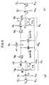
Gemäß Fig. 5 entspricht jeder der jeweils einer Zeile nzµ des für den Normalbetrieb vorgesehenen und in die beiden Hälften LZF und RZF unterteilten Zellenfelds zugeordnete Mittendekoder MDµ funktionell und schaltungstechnisch dem aus Fig. 3b bekannten NOR-Gatter samt zugehörigem Lasttransistor NTI eines Normaldekoders NDµ. Dem Mittendekoder MDµ schließen sich nach links der linke Schalter LSµ und nach rechts der rechte Schalter RSµ an. Der Anschluß erfolgt jeweils über einen Transfertransistor NT2i, NT2r wobei das Gate jedes Transfertransistors NT2i, NT2, mit dem Versorgungspotential VDD verbunden ist.According to FIG. 5, each corresponds to one line nzμ of that intended for normal operation and in the two halves LZF and RZF divided cell array associated center decoder MDµ functionally and in terms of circuitry of the NOR gate known from FIG. 3b together with the associated load transistor NTI of a normal decoder NDµ. The left switch LSµ is connected to the center decoder MDµ and the right switch RSµ to the right. The connection is made via a transfer transistor NT2i , NT2r , the gate of each transfer transistor NT2i , NT2 being connected to the supply potential VDD .
Funktionell entsprechen die beiden Transfertransistoren NT2, bzw. NT2, dem aus Fig. 3b bekannten Transfertransistor NT2. Der Transfertransistor NT2, ist an seinem dem Mittendekoder MDµ abgewandten stromführenden Anschluß mit dem Gate eines Transistors NT3, und der Transfertransistor NT2r in entsprechender Weise mit dem Gate eines Transistors NT3r verbunden. Die beiden Transistoren NT3, und NT3r entsprechen dem Transistor NT3 des in Fig. 3b gezeigten Normaldekoders NDu und sind dementsprechend an ihren Drainanschlüssen jeweils durch ein dem Aktivierungssignal 03 entsprechendes Aktivierungssignal 03, bzw. θ3r beaufschlagt, dessen Erzeugung bereits beschrieben wurde. Ebenso ist das aus Fig. 3b bekannte RS-Flip-Flop FF3 zweimal - und zwar in Gestalt des RS-Flip-Flops FF3, und des RS-Flip-Flops FF3r - vertreten, wobei das RS-Flip-Flop FF3, im linken Schalter LSµ und das RS-Flip-Flop FF3r im rechten Schalter RSµ enthalten sind. Weitere sachliche Erörterungen zu der in Fig. 5 gezeigten Ausgestaltung des Mittendekoders MDL und der beiden Schalter LSµ, RSµ samt deren Anschluß an die in der linken bzw. rechten Zellenfeldhälfte LZF bzw. RZF gelegene, für den Normalbetrieb vorgesehene Zeilenhälfte nzµl, bzw. nzµr dürften aufgrund der Ausführungen zu Fig. 3b nicht mehr erforderlich sein.Functionally, the two transfer transistors NT2 and NT2 correspond to the transfer transistor NT2 known from FIG. 3b. The transfer transistor NT2 is connected at itsr the center decoder MDμ remote from the current-carrying terminal connected to the gate of a transistor NT3, and the transfer transistor NT2r in a corresponding manner to the gate of the transistor NT3. The two transistors NT3 and NT3r correspond to the transistor NT3 of the normal decoder NDu shown in FIG. 3b and are accordingly acted upon at their drain connections by an
Die Erfindung ist anwendbar sowohl auf statische als auch auf dynamische Schreib-Lesespeicher. Sie ist insbesondere auch auf dynamische Schreib-Lesespeicher anwendbar, deren Speicherzellen als Ein-Transistor-Speicherzellen aufgebaut sind.The invention is applicable to both static and dynamic random access memories. In particular, it is also applicable to dynamic random access memories whose memory cells are constructed as one-transistor memory cells.
Claims (12)
Priority Applications (1)
| Application Number | Priority Date | Filing Date | Title |
|---|---|---|---|
| AT84115749TATE42647T1 (en) | 1984-08-02 | 1984-12-18 | INTEGRATED READ-WRITE MEMORY. |
Applications Claiming Priority (2)
| Application Number | Priority Date | Filing Date | Title |
|---|---|---|---|
| DE3428552 | 1984-08-02 | ||
| DE3428552 | 1984-08-02 |
Publications (2)
| Publication Number | Publication Date |
|---|---|
| EP0170727A1 EP0170727A1 (en) | 1986-02-12 |
| EP0170727B1true EP0170727B1 (en) | 1989-04-26 |
Family
ID=6242228
Family Applications (1)
| Application Number | Title | Priority Date | Filing Date |
|---|---|---|---|
| EP84115749AExpiredEP0170727B1 (en) | 1984-08-02 | 1984-12-18 | Integrated write-read memory |
Country Status (6)
| Country | Link |
|---|---|
| US (1) | US4737935A (en) |
| EP (1) | EP0170727B1 (en) |
| JP (1) | JP2523449B2 (en) |
| AT (1) | ATE42647T1 (en) |
| DE (1) | DE3477973D1 (en) |
| HK (1) | HK22992A (en) |
Families Citing this family (12)
| Publication number | Priority date | Publication date | Assignee | Title |
|---|---|---|---|---|
| DE3685654D1 (en)* | 1986-08-22 | 1992-07-16 | Ibm | DECODING METHOD AND CIRCUIT ARRANGEMENT FOR A REDUNDANT CMOS SEMICONDUCTOR MEMORY. |
| JP2639650B2 (en)* | 1987-01-14 | 1997-08-13 | 日本テキサス・インスツルメンツ株式会社 | Semiconductor device |
| NL8701085A (en)* | 1987-05-08 | 1988-12-01 | Philips Nv | MEMORY WITH REDUNDANT MEMORY SPACE. |
| JPS6454543A (en)* | 1987-08-25 | 1989-03-02 | Mitsubishi Electric Corp | Information processor |
| EP0327861B1 (en)* | 1988-02-10 | 1993-03-31 | Siemens Aktiengesellschaft | Redundancy decoder for an integrated semiconductor memory |
| US5022006A (en)* | 1988-04-01 | 1991-06-04 | International Business Machines Corporation | Semiconductor memory having bit lines with isolation circuits connected between redundant and normal memory cells |
| US5268319A (en)* | 1988-06-08 | 1993-12-07 | Eliyahou Harari | Highly compact EPROM and flash EEPROM devices |
| EP0935255A2 (en) | 1989-04-13 | 1999-08-11 | SanDisk Corporation | Flash EEPROM system |
| US7190617B1 (en)* | 1989-04-13 | 2007-03-13 | Sandisk Corporation | Flash EEprom system |
| US5157634A (en)* | 1990-10-23 | 1992-10-20 | International Business Machines Corporation | Dram having extended refresh time |
| US5257228A (en)* | 1991-05-16 | 1993-10-26 | Texas Instruments Incorporated | Efficiency improved DRAM row redundancy circuit |
| JP2004079843A (en)* | 2002-08-20 | 2004-03-11 | Renesas Technology Corp | Semiconductor storage device |
Family Cites Families (5)
| Publication number | Priority date | Publication date | Assignee | Title |
|---|---|---|---|---|
| US4228528B2 (en)* | 1979-02-09 | 1992-10-06 | Memory with redundant rows and columns | |
| US4441170A (en)* | 1980-09-30 | 1984-04-03 | Intel Corporation | Memory redundancy apparatus for single chip memories |
| US4358833A (en)* | 1980-09-30 | 1982-11-09 | Intel Corporation | Memory redundancy apparatus for single chip memories |
| JPS5782297A (en)* | 1980-11-11 | 1982-05-22 | Nippon Telegr & Teleph Corp <Ntt> | Semiconductor storage device |
| JPS58199496A (en)* | 1982-05-14 | 1983-11-19 | Hitachi Ltd | Semiconductor memory with defect relieving circuit |
- 1984
- 1984-12-18EPEP84115749Apatent/EP0170727B1/ennot_activeExpired
- 1984-12-18DEDE8484115749Tpatent/DE3477973D1/ennot_activeExpired
- 1984-12-18ATAT84115749Tpatent/ATE42647T1/ennot_activeIP Right Cessation
- 1985
- 1985-07-25USUS06/759,042patent/US4737935A/ennot_activeExpired - Lifetime
- 1985-07-29JPJP60167373Apatent/JP2523449B2/ennot_activeExpired - Fee Related
- 1992
- 1992-03-26HKHK229/92Apatent/HK22992A/ennot_activeIP Right Cessation
Also Published As
| Publication number | Publication date |
|---|---|
| HK22992A (en) | 1992-04-03 |
| JP2523449B2 (en) | 1996-08-07 |
| JPS6142800A (en) | 1986-03-01 |
| ATE42647T1 (en) | 1989-05-15 |
| DE3477973D1 (en) | 1989-06-01 |
| EP0170727A1 (en) | 1986-02-12 |
| US4737935A (en) | 1988-04-12 |
Similar Documents
| Publication | Publication Date | Title |
|---|---|---|
| EP0636258B1 (en) | Integrated semiconductor memory with redundancy arrangement | |
| DE69128446T2 (en) | Very fast redundant rows and columns for semiconductor memory | |
| DE3227464C2 (en) | Programmable circuit | |
| DE3716518C2 (en) | ||
| DE69122066T2 (en) | Semiconductor memory with pre-loaded redundancy multiplexer | |
| DE3382728T2 (en) | Semiconductor arrangement with spare memory cells. | |
| DE3724509A1 (en) | DYNAMIC RAM | |
| DE69125535T2 (en) | Semiconductor memory device | |
| EP0170727B1 (en) | Integrated write-read memory | |
| DE3138363A1 (en) | REDUNDANCY CIRCUIT FOR STORAGE | |
| DE3537015A1 (en) | SEMICONDUCTOR STORAGE | |
| EP0612074B1 (en) | Column redundancy device for a memory | |
| DE69627799T2 (en) | Redundancy circuit for storage devices with high-frequency addressing cycles | |
| EP0282976B1 (en) | Method and circuit arrangement for the parallel write-in of data in a semiconductor memory | |
| DE3101520A1 (en) | MONOLITHICALLY INTEGRATED SEMICONDUCTOR MEMORY | |
| EP0127015B1 (en) | Integrated digital mos semiconductor circuit | |
| DE68924843T2 (en) | TRANSISTOR BREAKTHROUGH PROTECTION CIRCUIT. | |
| EP0257120A1 (en) | Decoding method and circuit arrangement for a redundant CMOS semiconductor memory | |
| DE2128792A1 (en) | Circuit arrangement with at least one field effect transistor | |
| EP0961291A1 (en) | Fuse latch circuit | |
| EP0697659A1 (en) | Redundancy circuit for an integrated circuit semiconductor memory | |
| DE19507312C1 (en) | Semiconductor memory, the memory cells of which are combined to form individually addressable units and method for operating such memories | |
| DE69119141T2 (en) | Semiconductor memory device | |
| DE4124572C2 (en) | ||
| DE102021205318A1 (en) | Memory device and method for performing consecutive memory accesses |
Legal Events
| Date | Code | Title | Description |
|---|---|---|---|
| PUAI | Public reference made under article 153(3) epc to a published international application that has entered the european phase | Free format text:ORIGINAL CODE: 0009012 | |
| 17P | Request for examination filed | Effective date:19850102 | |
| AK | Designated contracting states | Designated state(s):AT DE FR GB IT NL | |
| 17Q | First examination report despatched | Effective date:19870918 | |
| GRAA | (expected) grant | Free format text:ORIGINAL CODE: 0009210 | |
| AK | Designated contracting states | Kind code of ref document:B1 Designated state(s):AT DE FR GB IT NL | |
| REF | Corresponds to: | Ref document number:42647 Country of ref document:AT Date of ref document:19890515 Kind code of ref document:T | |
| REF | Corresponds to: | Ref document number:3477973 Country of ref document:DE Date of ref document:19890601 | |
| ITF | It: translation for a ep patent filed | ||
| ET | Fr: translation filed | ||
| GBT | Gb: translation of ep patent filed (gb section 77(6)(a)/1977) | ||
| PLBE | No opposition filed within time limit | Free format text:ORIGINAL CODE: 0009261 | |
| STAA | Information on the status of an ep patent application or granted ep patent | Free format text:STATUS: NO OPPOSITION FILED WITHIN TIME LIMIT | |
| 26N | No opposition filed | ||
| ITTA | It: last paid annual fee | ||
| PGFP | Annual fee paid to national office [announced via postgrant information from national office to epo] | Ref country code:AT Payment date:20011121 Year of fee payment:18 | |
| PGFP | Annual fee paid to national office [announced via postgrant information from national office to epo] | Ref country code:FR Payment date:20011204 Year of fee payment:18 | |
| PGFP | Annual fee paid to national office [announced via postgrant information from national office to epo] | Ref country code:NL Payment date:20011206 Year of fee payment:18 Ref country code:GB Payment date:20011206 Year of fee payment:18 | |
| REG | Reference to a national code | Ref country code:GB Ref legal event code:IF02 | |
| PG25 | Lapsed in a contracting state [announced via postgrant information from national office to epo] | Ref country code:GB Free format text:LAPSE BECAUSE OF NON-PAYMENT OF DUE FEES Effective date:20021218 Ref country code:AT Free format text:LAPSE BECAUSE OF NON-PAYMENT OF DUE FEES Effective date:20021218 | |
| PG25 | Lapsed in a contracting state [announced via postgrant information from national office to epo] | Ref country code:NL Free format text:LAPSE BECAUSE OF NON-PAYMENT OF DUE FEES Effective date:20030701 | |
| GBPC | Gb: european patent ceased through non-payment of renewal fee | Effective date:20021218 | |
| NLV4 | Nl: lapsed or anulled due to non-payment of the annual fee | Effective date:20030701 | |
| PG25 | Lapsed in a contracting state [announced via postgrant information from national office to epo] | Ref country code:FR Free format text:LAPSE BECAUSE OF NON-PAYMENT OF DUE FEES Effective date:20030901 | |
| REG | Reference to a national code | Ref country code:FR Ref legal event code:ST | |
| PGFP | Annual fee paid to national office [announced via postgrant information from national office to epo] | Ref country code:DE Payment date:20040218 Year of fee payment:20 |