EP0168656B1 - An automatic degassing device in a reciprocating pump - Google Patents
An automatic degassing device in a reciprocating pumpDownload PDFInfo
- Publication number
- EP0168656B1 EP0168656B1EP19850107510EP85107510AEP0168656B1EP 0168656 B1EP0168656 B1EP 0168656B1EP 19850107510EP19850107510EP 19850107510EP 85107510 AEP85107510 AEP 85107510AEP 0168656 B1EP0168656 B1EP 0168656B1
- Authority
- EP
- European Patent Office
- Prior art keywords
- ball
- valve
- passage
- delivery
- degassing
- Prior art date
- Legal status (The legal status is an assumption and is not a legal conclusion. Google has not performed a legal analysis and makes no representation as to the accuracy of the status listed.)
- Expired
Links
Images

Classifications
- F—MECHANICAL ENGINEERING; LIGHTING; HEATING; WEAPONS; BLASTING
- F16—ENGINEERING ELEMENTS AND UNITS; GENERAL MEASURES FOR PRODUCING AND MAINTAINING EFFECTIVE FUNCTIONING OF MACHINES OR INSTALLATIONS; THERMAL INSULATION IN GENERAL
- F16K—VALVES; TAPS; COCKS; ACTUATING-FLOATS; DEVICES FOR VENTING OR AERATING
- F16K24/00—Devices, e.g. valves, for venting or aerating enclosures
- F16K24/04—Devices, e.g. valves, for venting or aerating enclosures for venting only
- F16K24/042—Devices, e.g. valves, for venting or aerating enclosures for venting only actuated by a float
- F16K24/044—Devices, e.g. valves, for venting or aerating enclosures for venting only actuated by a float the float being rigidly connected to the valve element, the assembly of float and valve element following a substantially translational movement when actuated, e.g. also for actuating a pilot valve
- F16K24/046—Devices, e.g. valves, for venting or aerating enclosures for venting only actuated by a float the float being rigidly connected to the valve element, the assembly of float and valve element following a substantially translational movement when actuated, e.g. also for actuating a pilot valve the assembly of float and valve element being a single spherical element
- F—MECHANICAL ENGINEERING; LIGHTING; HEATING; WEAPONS; BLASTING
- F04—POSITIVE - DISPLACEMENT MACHINES FOR LIQUIDS; PUMPS FOR LIQUIDS OR ELASTIC FLUIDS
- F04B—POSITIVE-DISPLACEMENT MACHINES FOR LIQUIDS; PUMPS
- F04B53/00—Component parts, details or accessories not provided for in, or of interest apart from, groups F04B1/00 - F04B23/00 or F04B39/00 - F04B47/00
- F04B53/06—Venting
Definitions
- This inventionrelates to an automatic degassing device in a reciprocating pump. More particularly, the invention relates to an automative degassing valve for suction of air in addition to liquid through a suction valve, or for pumping a volatile liquid capable of generating gas under a low pressure, in a general reciprocating pump having a piston, a plunger or a diaphragm as a reciprocating body.
- FR-A-1 591 836shows a pump with a degassing device.
- the inventorshave developed a mechanism for automatically discharging gases introduced initially or during operation into a pump or subsequently evaporated from a liquid within the pump chamber, in which a delivery line of the reciprocating pump is provided with a branched passage having a degasing valve.
- an object of the inventionis to provide an automatic degassing device in a reciprocating pump without necessity of additional fabrication of the pump, but only by replacing a joint on a delivery side with a degassing valve cartridge.
- the inventionprovides an automatic degassing device in a reciprocating pump having a reciprocating body, such as a piston or a diaphragm, and check valves for suction and delivery to provide a pumping function, in which a tubing directly behind a delivery valve is divided into branched passages for a discharged fluid and for a separated gas, in which a degassing valve is arranged in a passage directly upward, and in which a throttle valve means is arranged in the passage for the discharged fluid to generate a back pressure during the discharging operation.
- a reciprocating bodysuch as a piston or a diaphragm
- a liquidis introduced into an inlet 11 during a suction stroke and then through a two-step ball valve 12 and a suction line 16 in a liquid-contacting portion of the pump 1 into a pump chamber 3.
- a reference numeral 4represents a diaphragm, while a reference 5 represents a piston rod.
- the liquidis then pumped during a delivery stroke from the pump chamber 3 through a delivery line 21 and a two-step ball valve 22 into a delivery passage 26, which at its outlet 28 is provided with a constricted back-pressure valve 40 (see Fig. 2) having at its lower end a somewhat constricting effect and producing a back pressure.
- the passage 31is made narrower than the other branched delivery passage 27 (for example, less than 2 of a diameter of the delivery passage 26).
- a ball 32 made of a material having a lower specific gravity than the liquid(for example, the ball 32 of polypropylene (SG 0.9) for the liquid of SG 1 or water) is arranged in a valve chamber 38.
- the chamber 38is filled with the gas, the ball 32 is not subjected to a floating action and therefore falls down from the seat 33.
- the gasis thus discharged from a degassing hole 39 via a hole of the seat 33.
- the ball 32is urged against the seat 33 due to the floating action for sealing or preventing leakage of the liquid.
- a ball 34 made of a heavier materialis placed on a seat 35.
- the ball 34is urged against the seat 35 for sealing upon a lower pressure of the liquid below an atmospheric pressure during a suction stroke, thereby preventing suction of air from a degassing hole 39.
- the degassing procedure according to the inventionmay be summarized as follows.
- the degassing valve devicemay discharge the gas prevent in the pump chamber during the delivery stroke and prevent the air suction dfuring the the suction stroke.
- the deviceensures the normal pumping function.
- a throttle valveis desirably arranged at a downstream from the delivery passage for providing a slight back-pressure to automatically discharge any gas in the pump through the degassing device.
- the back-pressure applied by a spring load in a constricting mannermay be in the range of 0.8 to 1.0 Bar (kgf/cm 2 ), independent from a static head.
Landscapes
- Engineering & Computer Science (AREA)
- General Engineering & Computer Science (AREA)
- Mechanical Engineering (AREA)
- Details Of Reciprocating Pumps (AREA)
- Reciprocating Pumps (AREA)
Description
- This invention relates to an automatic degassing device in a reciprocating pump. More particularly, the invention relates to an automative degassing valve for suction of air in addition to liquid through a suction valve, or for pumping a volatile liquid capable of generating gas under a low pressure, in a general reciprocating pump having a piston, a plunger or a diaphragm as a reciprocating body.
- There have been proposed several degassing mechanisms having special structures exclusively for degassing (for example, Japanese Patent Publication 12031/82), in which a valve activated by a spring is opened in an appropriate equilibrium condition of pressure for discharging only gases. Also FR-A-1 591 836 shows a pump with a degassing device.
- Further, there is known another method in which a valve is operated manually in consideration of a gaseous state for discharging gases. In this method, however, an apparatus is complicated or a troublesome manual operation is needed.
- When a gas is introduced into a pump chamber, a pumping function is considerably decreased due to compression of the gas. Especially in a small type of an electrically driven diaphragm pump, this phenomenon is significant thereby to prohibit an appropriate pumping action. This phenomenon is also regarded as a severe problem in common reciprocating pumps.
- In order to solve the above problems, the applicant has developed a mechanism of very- simple and low cost for ensuring a pumping action of automatically discharging only the gases, and filed patent application therefore (Jap- nese Patent Application 103402/84; publication number 6-256 572 - published on 18.12.85). This mechanism is shown in Figure 3, in which the degassing action may be ensured but a liquid- contacting element is too large and thus uneconomical for a pump of lower compacity. Further, a larger space of delivery is needed, resulting in a considerably large pump chamber and reduction in a pumping efficiency.
- In view of the foregoing, the inventors have developed a mechanism for automatically discharging gases introduced initially or during operation into a pump or subsequently evaporated from a liquid within the pump chamber, in which a delivery line of the reciprocating pump is provided with a branched passage having a degasing valve.
- Accordingly, an object of the invention is to provide an automatic degassing device in a reciprocating pump without necessity of additional fabrication of the pump, but only by replacing a joint on a delivery side with a degassing valve cartridge.
- In order to achieve the above object, the invention provides an automatic degassing device in a reciprocating pump having a reciprocating body, such as a piston or a diaphragm, and check valves for suction and delivery to provide a pumping function, in which a tubing directly behind a delivery valve is divided into branched passages for a discharged fluid and for a separated gas, in which a degassing valve is arranged in a passage directly upward, and in which a throttle valve means is arranged in the passage for the discharged fluid to generate a back pressure during the discharging operation.
- The invention will now be described in more detail for better understanding with reference to the accompanying drawings.
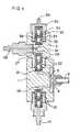
- Figure 1 is a sectional view of a liquid-contacting portion of a small diaphragm pump having a device according to the invention, in which non- essential parts for suction and delivery valves are omitted;
- Figure 2 is a schematic diagram of the pump according to the invention, including a back pressure valve in a degassing mechanism; and
- Figure 3 is a sectional view of an important portion of a pump according to the Japanese Patent application No. 103402/84.
- Figure 1 shows one embodiment of an automatic degassing device according to the invention, in which a two-step valve structure for each of suction and delivery valves is employed for improving its performance.
- A liquid is introduced into an
inlet 11 during a suction stroke and then through a two-step ball valve 12 and asuction line 16 in a liquid-contacting portion of thepump 1 into apump chamber 3. A reference numeral 4 represents a diaphragm, while areference 5 represents a piston rod. The liquid is then pumped during a delivery stroke from thepump chamber 3 through adelivery line 21 and a two-step ball valve 22 into adelivery passage 26, which at itsoutlet 28 is provided with a constricted back-pressure valve 40 (see Fig. 2) having at its lower end a somewhat constricting effect and producing a back pressure. Since an inner pressure in adelivery passage 27 leading to theball 32 via apassage 31 branched from thedelivery passage 26 is slightly increased by an action of the back-pressure valve 40, the gas having a higher specific volume than the liquid is urged into thepassage 31. In order to enhance such action, thepassage 31 is made narrower than the other branched delivery passage 27 (for example, less than 2 of a diameter of the delivery passage 26). - A
ball 32 made of a material having a lower specific gravity than the liquid (for example, theball 32 of polypropylene (SG 0.9) for the liquid ofSG 1 or water) is arranged in avalve chamber 38. When thechamber 38 is filled with the gas, theball 32 is not subjected to a floating action and therefore falls down from theseat 33. The gas is thus discharged from adegassing hole 39 via a hole of theseat 33. When the gas is discharged and thechamber 38 becomes filled with the liquid, theball 32 is urged against theseat 33 due to the floating action for sealing or preventing leakage of the liquid. - On the other hand, a
ball 34 made of a heavier material is placed on aseat 35. Thus, theball 34 is urged against theseat 35 for sealing upon a lower pressure of the liquid below an atmospheric pressure during a suction stroke, thereby preventing suction of air from adegassing hole 39. - The degassing procedure according to the invention may be summarized as follows.
- 1. When the gas present in the
chamber 38, it is discharged in a delivery stroke through a gap between theball 32 and theseat 33. - 2. When the
chamber 38 is filled with the liquid, theball 32 is urged against theseat 33 due to floatation, thereby preventing leakage of the liquid. - 3. When the
delivery passage 26 is filled with the liquid during a suction stroke, the close contact of theball 34 against theseat 35 prevents the air from flowing thereinto. - Thus, in accordance with the invention, the degassing valve device may discharge the gas prevent in the pump chamber during the delivery stroke and prevent the air suction dfuring the the suction stroke. When the pump is filled with the liquid, the device ensures the normal pumping function. In this case, a throttle valve is desirably arranged at a downstream from the delivery passage for providing a slight back-pressure to automatically discharge any gas in the pump through the degassing device. An experiment shows that the absence of the back-
pressure valve 40 in Fig. 2 (namely application of a static pressure only) necessitates a considerably longer period of time for discharging the air which has been sucked through a suction inlet during the pumping operation, and that the complete degassing is impossible, resulting in reduction of the pumping efficiency. The back-pressure applied by a spring load in a constricting manner may be in the range of 0.8 to 1.0 Bar (kgf/cm2), independent from a static head.
Claims (2)
Applications Claiming Priority (2)
| Application Number | Priority Date | Filing Date | Title |
|---|---|---|---|
| JP59132793AJPS6111473A (en) | 1984-06-27 | 1984-06-27 | Automatic gas vent apparatus in reciprocating pump |
| JP132793/84 | 1984-06-27 |
Publications (2)
| Publication Number | Publication Date |
|---|---|
| EP0168656A1 EP0168656A1 (en) | 1986-01-22 |
| EP0168656B1true EP0168656B1 (en) | 1988-08-17 |
Family
ID=15089683
Family Applications (1)
| Application Number | Title | Priority Date | Filing Date |
|---|---|---|---|
| EP19850107510ExpiredEP0168656B1 (en) | 1984-06-27 | 1985-06-18 | An automatic degassing device in a reciprocating pump |
Country Status (3)
| Country | Link |
|---|---|
| EP (1) | EP0168656B1 (en) |
| JP (1) | JPS6111473A (en) |
| DE (1) | DE3564471D1 (en) |
Cited By (1)
| Publication number | Priority date | Publication date | Assignee | Title |
|---|---|---|---|---|
| DE19717043C2 (en)* | 1997-04-23 | 2003-05-22 | Daimler Chrysler Ag | Method for dewatering and / or degassing hydraulic fluids, device for carrying out the method and use of the device |
Families Citing this family (9)
| Publication number | Priority date | Publication date | Assignee | Title |
|---|---|---|---|---|
| DE3820887A1 (en)* | 1988-06-21 | 1989-12-28 | Pierburg Gmbh | FUEL PUMP |
| JPH07101700B2 (en)* | 1988-12-07 | 1995-11-01 | 松下電器産業株式会社 | Implementation method |
| DE4418314C1 (en)* | 1994-05-26 | 1996-01-04 | Prominent Dosiertechnik Gmbh | Liquid metering pump |
| DE19538134A1 (en)* | 1995-10-13 | 1997-04-17 | Alldos Eichler Gmbh | Dosing pump |
| JP3570895B2 (en)* | 1998-07-02 | 2004-09-29 | 日本碍子株式会社 | Discharge device for raw materials and fuel |
| JP5210135B2 (en)* | 2008-12-01 | 2013-06-12 | 日機装エイコー株式会社 | Reciprocating pump with degassing mechanism |
| CN103703251B (en)* | 2011-08-25 | 2016-12-21 | 艺康股份有限公司 | Self-venting diaphragm pump for metering fluids and corresponding method |
| WO2018109905A1 (en) | 2016-12-15 | 2018-06-21 | 株式会社イワキ | Reciprocating pump |
| CN108571603B (en)* | 2017-07-12 | 2024-01-09 | 杭州南方赛珀工业设备有限公司 | Fixed articulated check valve |
Family Cites Families (6)
| Publication number | Priority date | Publication date | Assignee | Title |
|---|---|---|---|---|
| JPS4843121Y1 (en)* | 1965-05-15 | 1973-12-13 | ||
| JPS446294Y1 (en)* | 1966-04-14 | 1969-03-07 | ||
| CH457146A (en)* | 1967-11-20 | 1968-05-31 | Glutz Blotzheim Nachfolger Ag | Electromagnetic oscillating armature pump |
| US4104004A (en)* | 1976-11-12 | 1978-08-01 | The De Laval Separator Company | Air eliminator for pumps |
| DE3040478C2 (en)* | 1980-10-28 | 1986-07-10 | Uraca Pumpenfabrik GmbH & Co KG, 7432 Bad Urach | Pump or the like. hydraulic working machine |
| JPS5970092U (en)* | 1982-11-04 | 1984-05-12 | 日機装株式会社 | reciprocating pump device |
- 1984
- 1984-06-27JPJP59132793Apatent/JPS6111473A/enactivePending
- 1985
- 1985-06-18EPEP19850107510patent/EP0168656B1/ennot_activeExpired
- 1985-06-18DEDE8585107510Tpatent/DE3564471D1/ennot_activeExpired
Cited By (1)
| Publication number | Priority date | Publication date | Assignee | Title |
|---|---|---|---|---|
| DE19717043C2 (en)* | 1997-04-23 | 2003-05-22 | Daimler Chrysler Ag | Method for dewatering and / or degassing hydraulic fluids, device for carrying out the method and use of the device |
Also Published As
| Publication number | Publication date |
|---|---|
| JPS6111473A (en) | 1986-01-18 |
| DE3564471D1 (en) | 1988-09-22 |
| EP0168656A1 (en) | 1986-01-22 |
Similar Documents
| Publication | Publication Date | Title |
|---|---|---|
| US6913448B2 (en) | Load-regulating device for scroll type compressors | |
| US3730215A (en) | Diaphragm controlled air relief valve | |
| JP3830524B2 (en) | Fuel injection device for internal combustion engine | |
| EP0168656B1 (en) | An automatic degassing device in a reciprocating pump | |
| KR950008959A (en) | Fuel supply | |
| US5888056A (en) | Diaphragm pump | |
| SE8506128L (en) | ELECTROMAGNETIC MANOVATED PISTON PUMP | |
| US4278406A (en) | Electromagnetic pump | |
| US3514231A (en) | Reciprocating pump for marine toilets | |
| GB2161221A (en) | Flexible chamber pump | |
| KR100291161B1 (en) | Diaphragm pump | |
| US4415314A (en) | Metering pump | |
| US2077394A (en) | Liquid sealed pump | |
| KR200168396Y1 (en) | Check valve | |
| US2215815A (en) | Air control device | |
| US5711655A (en) | Pump system using a vacuum chamber and mechanical pump combinations | |
| US4494560A (en) | Self-priming system for liquid pumps | |
| GB2138888A (en) | Priming valve and priming circuit for impeller pumps | |
| JPH11324906A (en) | pump | |
| JPS60220203A (en) | Pressure boosting type high pressure vessel | |
| KR200295501Y1 (en) | Hand-operated Spray Pump for Use in Inverted Position | |
| RU1800137C (en) | Pump-and-ejector unit | |
| SU1160104A1 (en) | Electromagnetic diaphragm compressor | |
| JPH0213818Y2 (en) | ||
| KR940000699Y1 (en) | Hydraulic ram |
Legal Events
| Date | Code | Title | Description |
|---|---|---|---|
| PUAI | Public reference made under article 153(3) epc to a published international application that has entered the european phase | Free format text:ORIGINAL CODE: 0009012 | |
| AK | Designated contracting states | Designated state(s):CH DE FR GB IT LI NL | |
| 17P | Request for examination filed | Effective date:19860605 | |
| 17Q | First examination report despatched | Effective date:19870914 | |
| GRAA | (expected) grant | Free format text:ORIGINAL CODE: 0009210 | |
| AK | Designated contracting states | Kind code of ref document:B1 Designated state(s):CH DE FR GB IT LI NL | |
| ITF | It: translation for a ep patent filed | ||
| REF | Corresponds to: | Ref document number:3564471 Country of ref document:DE Date of ref document:19880922 | |
| ET | Fr: translation filed | ||
| PLBE | No opposition filed within time limit | Free format text:ORIGINAL CODE: 0009261 | |
| STAA | Information on the status of an ep patent application or granted ep patent | Free format text:STATUS: NO OPPOSITION FILED WITHIN TIME LIMIT | |
| 26N | No opposition filed | ||
| PGFP | Annual fee paid to national office [announced via postgrant information from national office to epo] | Ref country code:DE Payment date:20000530 Year of fee payment:16 | |
| PGFP | Annual fee paid to national office [announced via postgrant information from national office to epo] | Ref country code:GB Payment date:20000607 Year of fee payment:16 | |
| PGFP | Annual fee paid to national office [announced via postgrant information from national office to epo] | Ref country code:FR Payment date:20000616 Year of fee payment:16 | |
| PGFP | Annual fee paid to national office [announced via postgrant information from national office to epo] | Ref country code:NL Payment date:20000620 Year of fee payment:16 | |
| PGFP | Annual fee paid to national office [announced via postgrant information from national office to epo] | Ref country code:CH Payment date:20000623 Year of fee payment:16 | |
| PG25 | Lapsed in a contracting state [announced via postgrant information from national office to epo] | Ref country code:GB Free format text:LAPSE BECAUSE OF NON-PAYMENT OF DUE FEES Effective date:20010618 | |
| PG25 | Lapsed in a contracting state [announced via postgrant information from national office to epo] | Ref country code:LI Free format text:LAPSE BECAUSE OF NON-PAYMENT OF DUE FEES Effective date:20010630 Ref country code:CH Free format text:LAPSE BECAUSE OF NON-PAYMENT OF DUE FEES Effective date:20010630 | |
| PG25 | Lapsed in a contracting state [announced via postgrant information from national office to epo] | Ref country code:NL Free format text:LAPSE BECAUSE OF NON-PAYMENT OF DUE FEES Effective date:20020101 | |
| GBPC | Gb: european patent ceased through non-payment of renewal fee | Effective date:20010618 | |
| REG | Reference to a national code | Ref country code:CH Ref legal event code:PL | |
| PG25 | Lapsed in a contracting state [announced via postgrant information from national office to epo] | Ref country code:FR Free format text:LAPSE BECAUSE OF NON-PAYMENT OF DUE FEES Effective date:20020228 | |
| NLV4 | Nl: lapsed or anulled due to non-payment of the annual fee | Effective date:20020101 | |
| PG25 | Lapsed in a contracting state [announced via postgrant information from national office to epo] | Ref country code:DE Free format text:LAPSE BECAUSE OF NON-PAYMENT OF DUE FEES Effective date:20020403 |