EP0166885A2 - Radiotelephone system - Google Patents
Radiotelephone systemDownload PDFInfo
- Publication number
- EP0166885A2 EP0166885A2EP85104804AEP85104804AEP0166885A2EP 0166885 A2EP0166885 A2EP 0166885A2EP 85104804 AEP85104804 AEP 85104804AEP 85104804 AEP85104804 AEP 85104804AEP 0166885 A2EP0166885 A2EP 0166885A2
- Authority
- EP
- European Patent Office
- Prior art keywords
- radio
- central
- channel
- station
- cells
- Prior art date
- Legal status (The legal status is an assumption and is not a legal conclusion. Google has not performed a legal analysis and makes no representation as to the accuracy of the status listed.)
- Withdrawn
Links
- 230000005540biological transmissionEffects0.000claimsabstractdescription24
- 230000008878couplingEffects0.000claimsdescription8
- 238000010168coupling processMethods0.000claimsdescription8
- 238000005859coupling reactionMethods0.000claimsdescription8
- 238000010586diagramMethods0.000description3
- 238000004891communicationMethods0.000description1
- 238000011161developmentMethods0.000description1
- 230000018109developmental processEffects0.000description1
- 239000011159matrix materialSubstances0.000description1
- 238000000034methodMethods0.000description1
- 230000002093peripheral effectEffects0.000description1
Images

Classifications
- H—ELECTRICITY
- H04—ELECTRIC COMMUNICATION TECHNIQUE
- H04W—WIRELESS COMMUNICATION NETWORKS
- H04W16/00—Network planning, e.g. coverage or traffic planning tools; Network deployment, e.g. resource partitioning or cells structures
- H—ELECTRICITY
- H04—ELECTRIC COMMUNICATION TECHNIQUE
- H04W—WIRELESS COMMUNICATION NETWORKS
- H04W16/00—Network planning, e.g. coverage or traffic planning tools; Network deployment, e.g. resource partitioning or cells structures
- H04W16/24—Cell structures
- H04W16/32—Hierarchical cell structures
- H—ELECTRICITY
- H04—ELECTRIC COMMUNICATION TECHNIQUE
- H04W—WIRELESS COMMUNICATION NETWORKS
- H04W52/00—Power management, e.g. Transmission Power Control [TPC] or power classes
- H04W52/04—Transmission power control [TPC]
- H04W52/38—TPC being performed in particular situations
- H04W52/42—TPC being performed in particular situations in systems with time, space, frequency or polarisation diversity
Definitions
- the inventionrelates to a radio telephone system according to the type specified in the preamble of claim 1.
- Radio telephone systemsare known (e.g. Funkschau, 1984, number 7, pages 57 to 59), in which a radio area is divided into radio cells, each with a central radio station. Mobile radio telephones can operate within the entire radio area and connect to participants in a telephone network via the central radio stations.
- a disadvantage of the known radio telephone systemsis that mobile radio telephones to be held in the hand cannot be used. Because of the low battery capacity, the transmission power of such radio telephones is only about 1/10 to 1/3 of the transmission power of a mobile radio telephone installed in a motor vehicle. Because of the relationship P - E2. r 2 , in which P is the transmission power of the radio telephone, E the field strength and r the transmitter radius or the range, can only be expected for 1/10 of the transmission power with about 1/3 of the range.
- the present inventionis based on the object of redesigning a radio telephone system in such a way that, with little additional outlay, in addition to mobile radio telephones installed in motor vehicles, mobile radio telephones with a comparatively low transmission power that can be held in the hand can be used without the restrictions mentioned.
- the radio telephone system according to the invention with the characterizing features of claim 1is also suitable for hand-held mobile radio telephones with a short range, without requiring a higher technical outlay for them.
- the additional effort for the overall systemis also very low.
- Another advantageis that the transmission quality within the entire radio telephone system improves significantly.
- a radio telephone systemis particularly advantageous in which the central radio station simultaneously activates the multichannel radio transmission device of the central radio transmission station corresponding to this voice channel by switching a multi-channel receiver to a free voice channel and a common coupling and transmission device of the central radio station switches the voice connection paths. This has the advantage that normal four-wire switching networks can be used.
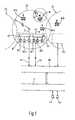
- radio telephone systemshave at least one radio area which is divided into a plurality of radio cells Z1, Z2 ... which partially overlap.
- Each radio cellwhich in the drawing has the shape of a circle for the sake of simplicity, contains in or near its center a fixed central radio station B1, B2 ... with m radio transmitters and m radio receivers BS1, BS2 ..., BEI, BE2. .. corresponding to m different language channels.
- the radio transmitting devicesare connected to a transmitting antenna S via a common coupling arrangement KS and the radio receiving devices are connected to a receiving antenna E via a common coupling arrangement KE; other antenna arrangements are also conceivable.
- Each radio transmitter and radio receiver of a central radio stationis connected, for example, via a four-wire line VI, V2 ... to a coupling and transmission device KO.
- a telephone network P with subscriber stations TN1, TN2 ...connects to the latter device.
- the coupling and transmission devicecontains means for determining the transmission quality, for switching the central radio station when changing cells and the like.
- Mobile radio telephones M11, M12 ...which are preferably installed in motor vehicles, operate within a radio cell, for example radio cell Z1.
- the transmission powers of the radio transmitters and radio receivers BS1, BS2 ..., BEI, BE2 ... of the central radio stations Bl, B2 ... as well as the mobile radio telephones Mll, M12, M21 ...are dimensioned in such a way that perfect radio communication in is possible in both directions.
- the transmitter radius SR B of the fixed radio station B1is entered, which at the same time corresponds to the radius of the radio cell Z1.
- each radio cellfor example the radio cell Zl in Fig. 2 is divided into n receive cells, for example E11 ... E 17.
- each receiving cellthere is a fixed multichannel receiver BE11, BE12 ... in a central location.
- a central radio station B1In comparison to the central radio station B1 in FIG. 1, a central radio station B1 'contains stationary multichannel radio receivers, in FIG Radio transmitter BS1, BS2 ...
- the transmitter radius SR H of the mobile radio telephones H to be held in the handis then sufficient in any case to reach one of the fixed multi-channel radio receivers, for example BE13.
- the fixed central radio station B1 'is provided with a channel switching device KU, which ensures that the multi-channel radio receivers, for example the radio receiver BE12, are switched from the central radio station B1' to one of the m possible voice channels. If a mobile radio telephone H changes from a receiving cell to an adjacent receiving cell, for example from E13 to E12, the channel switching device KU switches the receiver BE12 to a suitable radio channel and at the same time switches the channel speech paths in the receiving switching matrix KE. The switchover occurs so quickly that the participants hardly notice the switchover process.
- the channel switchover device KUnot only switches the multi-channel radio receivers to a specific radio channel, but also switches the central radio transmitter BS1, BS2 ... coordinated with the radio channel concerned.
- the stationary multi-channel radio receivers BE11, BE12 ... and the stationary radio transmitters BS1, BS2 ...are preferably connected to the coupling and transmission device KO (see FIG. 1) via a two-wire line.
- mobile radio telephones H to be held in the handonly have about 1/10 of the transmission power of mobile radio telephones installed in motor vehicles.
- the transmitter radius of the mobile radio telephones to be held in the handis only about 1/3 of the transmitter radius of a mobile radio telephone installed in a motor vehicle, which means that the reception cells Ell, E12 ... likewise only about 1 / 10 of the area of normal radio cells Z1, Z2 ... may have.
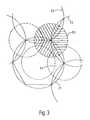
- the larger transmit cellsare overlaid by a network of smaller receive cells in larger numbers.
- the reception cells Ecan also be assigned a plurality of transmission cells, for example Z1, Z2, Z3; see. 3, receive cell E2 and transmit cells Z1, Z2, Z3.
Landscapes
- Engineering & Computer Science (AREA)
- Computer Networks & Wireless Communication (AREA)
- Signal Processing (AREA)
- Mobile Radio Communication Systems (AREA)
Abstract
Translated fromGerman
Description
Translated fromGermanDie Erfindung betrifft ein Funktelefonsystem nach der im Oberbegriff des Anspruchs 1 angegebenen Gattung.The invention relates to a radio telephone system according to the type specified in the preamble of
Es sind Funktelefonsysteme bekannt (z. B. Funkschau, 1984, Heft 7, Seiten 57 bis 59), bei denen ein Funkgebiet in Funkzellen mit je einer zentralen Funkstation aufgeteilt ist. Innerhalb des gesamten Funkgebietes können mobile Funktelefone operieren und über die zentralen Funkstationen mit Teilnehmern eines Telefonnetzes in Verbindung treten. Ein Nachteil der bekannten Funktelefonsysteme besteht darin, daß in der Hand zu haltende mobile Funktelefone nicht eingesetzt werden können. Die Sendeleistung derartiger Funktelefone beträgt nämlich wegen der geringen Batteriekapazität nur etwa 1/10 bis 1/3 der Sendeleistung eines in einem Kraftfahrzeug eingebauten mobilen Funktelefons. Aufgrund der Beziehung P - E2 . r2, worin P die Sendeleistung des Funktelefons, E die Feldstärke und r der Senderadius bzw. die Reichweite sind, kann bei 1/10 der Sendeleistung nur noch mit etwa 1/3 der Reichweite gerechnet werden. Für die umgekehrte Obertragungsrichtung von der zentralen Funkstation zu einem in der Hand zu haltenden mobilen Funktelefon besteht dagegen dieses Problem nur in geringerem Maße, sofern die Antenne des Funktelefons entsprechend optimiert ist. In einem Funkversorgungsgebiet, das in der üblichen Weise in Funkzellen bestimmter Größe aufgeteilt ist, können bisher somit neben Kraftfahrzeug-Funkstationen keine in der Hand zu haltenden mobilen Funktelefone eingesetzt werden, ohne Einschränkungen der Reichweite und Obertragungsqualität in Kauf nehmen zu müssen.Radio telephone systems are known (e.g. Funkschau, 1984, number 7, pages 57 to 59), in which a radio area is divided into radio cells, each with a central radio station. Mobile radio telephones can operate within the entire radio area and connect to participants in a telephone network via the central radio stations. A disadvantage of the known radio telephone systems is that mobile radio telephones to be held in the hand cannot be used. Because of the low battery capacity, the transmission power of such radio telephones is only about 1/10 to 1/3 of the transmission power of a mobile radio telephone installed in a motor vehicle. Because of the relationship P - E2. r2 , in which P is the transmission power of the radio telephone, E the field strength and r the transmitter radius or the range, can only be expected for 1/10 of the transmission power with about 1/3 of the range. For the reverse direction of transmission from the central radio station to a mobile radio telephone to be held in the hand, however, this problem only exists to a lesser extent, provided the antenna of the radio telephone is optimized accordingly. In a radio coverage area, which is divided in the usual way into radio cells of a certain size, no mobile radio telephones can be used in addition to motor vehicle radio stations without having to accept the range and transmission quality.
Der vorliegenden Erfindung liegt die Aufgabe zugrunde, ein Funktelefonsystem derart umzugestalten, daß bei geringem zusätzlichen Aufwand neben in Kraftfahrzeugen eingebauten mobilen Funktelefonen auch in der Hand zu haltende mobile Funktelefone mit vergleichsweise kleiner Sendeleistung ohne die erwähnten Einschränkungen zum Einsatz gelangen können.The present invention is based on the object of redesigning a radio telephone system in such a way that, with little additional outlay, in addition to mobile radio telephones installed in motor vehicles, mobile radio telephones with a comparatively low transmission power that can be held in the hand can be used without the restrictions mentioned.
Das erfindungsgemäße Funktelefonsystem mit den kennzeichnenden Merkmalen des Anspruchs 1 eignet sich auch für in der Hand zu haltende mobile Funktelefone geringer Reichweite, ohne daß für diese ein höherer technischer Aufwand nötig ist. Der Zusatzaufwand für das Gesamtsystem ist ebenfalls sehr gering. Als weiterer Vorteil ist anzusehen, daß sich die Obertragungsqualität innerhalb des gesamten Funktelefonsystems deutlich verbessert.The radio telephone system according to the invention with the characterizing features of
Mit den in den Unteransprüchen aufgeführten Maßnahmen sind vorteilhafte Weiterbildungen und Verbesserungen des im Anspruch 1 angegebenen Funktelefonsystems möglich. Besonders vorteilhaft ist ein Funktelefonsystem, bei dem die zentrale Funkstation mit der Umschaltung eines Mehrkanalempfängers auf einen freien Sprachkanal gleichzeitig das diesem Sprachkanal entsprechende Mehrkanalfunksendegerät der zentralen Funksendestation aktiviert und eine gemeinsame Koppel- und Obertragungseinrichtung der zentralen Funkstation die Sprechverbindungswege umschaltet. Damit ist der Vorteil verbunden, daß normale Vierdraht-Koppelfelder verwendet werden können.With the measures listed in the subclaims, advantageous developments and improvements of the radio telephone system specified in
Ein Ausführungsbeispiel der Erfindung ist in der Zeichnung an Hand zweier Figuren dargestellt und in der nachfolgenden Beschreibung näher erläutert. Die Zeichnung zeigt in
- Fig. 1 ein stark vereinfachtes Blockschaltbild eines bekannten Funktelefonsystems,
- Fig. 2 ein Blockschaltbild einer erfindungsgemäßen Funkzelle in einer ersten Ausführungsform und
- Fig. 3 ein Blockschaltbild einer erfindungsgemäßen Funkzelle in einer zweiten Ausführungsform.
- 1 is a very simplified block diagram of a known radio telephone system,
- Fig. 2 is a block diagram of a radio cell according to the invention in a first embodiment and
- Fig. 3 is a block diagram of a radio cell according to the invention in a second embodiment.
Bekannte Funktelefonsysteme weisen nach Fig. 1 mindestens ein Funkgebiet auf, das in mehrere Funkzellen Z1, Z2 ... aufgeteilt ist, die sich teilweise überlappen. Jede Funkzelle, die in der Zeichnung der Einfachheit halber die Form eines Kreises hat, enthält in oder nahe ihrem Mittelpunkt eine ortsfeste zentrale Funkstation Bl, B2 ... mit m Funksende- und m Funkempfangsgeräten BS1, BS2 ..., BEI, BE2 ... entsprechend m verschiedenen Sprachkanälen. Die Funksendegeräte sind über eine gemeinsame Koppelanordnung KS mit einer Sendeantenne S und die Funkempfangsgeräte über eine gemeinsame Koppelanordnung KE mit einer Empfangsantenne E verbunden; andere Antennenanordnungen sind ebenfalls denkbar. Jedes Funksende- und Funkempfangsgerät einer zentralen Funkstation steht beispielsweise über eine Vierdrahtleitung Vl, V2 ... mit einer Koppel- und Obertragungseinrichtung KO in Verbindung. An die zuletzt genannte Einrichtung schließt sich ein Telefonnetz P mit Teilnehmerstationen TN1, TN2 ... an. Die Koppel-und Obertragungseinrichtung enthält in bekannter Weise Mittel zum Feststellen der Obertragungsqualität, zum Umschalten der zentralen Funkstation beim Zellenwechsel und dergleichen.Known radio telephone systems according to FIG. 1 have at least one radio area which is divided into a plurality of radio cells Z1, Z2 ... which partially overlap. Each radio cell, which in the drawing has the shape of a circle for the sake of simplicity, contains in or near its center a fixed central radio station B1, B2 ... with m radio transmitters and m radio receivers BS1, BS2 ..., BEI, BE2. .. corresponding to m different language channels. The radio transmitting devices are connected to a transmitting antenna S via a common coupling arrangement KS and the radio receiving devices are connected to a receiving antenna E via a common coupling arrangement KE; other antenna arrangements are also conceivable. Each radio transmitter and radio receiver of a central radio station is connected, for example, via a four-wire line VI, V2 ... to a coupling and transmission device KO. A telephone network P with subscriber stations TN1, TN2 ... connects to the latter device. In a known manner, the coupling and transmission device contains means for determining the transmission quality, for switching the central radio station when changing cells and the like.
Innerhalb einer Funkzelle, zum Beispiel der Funkzelle Z1, operieren mobile Funktelefone M11, M12 ..., die vorzugsweise in Kraftfahrzeugen eingebaut sind. Die Sendeleistungen der Funksende- und Funkempfangsgeräte BS1, BS2 ..., BEI, BE2 ... der zentralen Funkstationen Bl, B2 ... sowie der mobilen Funktelefone Mll, M12, M21 ... sind derart bemessen, daß ein einwandfreier Funkverkehr in beiden Richtungen möglich ist. In Fig. 1 ist der Senderadius-SRB der ortsfesten Funkstation B1 eingetragen, der gleichzeitig dem Radius der Funkzelle Z1 entspricht.Mobile radio telephones M11, M12 ..., which are preferably installed in motor vehicles, operate within a radio cell, for example radio cell Z1. The transmission powers of the radio transmitters and radio receivers BS1, BS2 ..., BEI, BE2 ... of the central radio stations Bl, B2 ... as well as the mobile radio telephones Mll, M12, M21 ... are dimensioned in such a way that perfect radio communication in is possible in both directions. In Fig. 1, the transmitter radius SRB of the fixed radio station B1 is entered, which at the same time corresponds to the radius of the radio cell Z1.
Besteht nun der Wunsch, in das Funktelefonsystem auch in der Hand zu haltende mobile Funktelefone H einzubeziehen, so ergibt sich wegen der geringeren Sendeleistung dieser Geräte ein kleinerer Senderadius SRH; vgl. Fig. 1. Nach der Erfindung wird deshalb jede Funkzelle, zum Beispiel die Funkzelle Zl in Fig. 2, in n Empfangszellen, zum Beispiel E11... E 17, aufgeteilt. In jeder Empfangszelle befindet sich in zentraler Lage ein ortsfester Mehrkanalempfänger BEll, BE12 ... Eine zentrale Funkstation Bl' enthält im Vergleich zu der zentralen Funkstation B1 in Fig. 1 m/n ortsfeste Mehrkanalfunkempfänger, in Fig. 2 den Empfänger BE11 und m ortsfeste Funksender BS1, BS2 ... Der Senderadius SRH der in der Hand zu haltenden mobilen Funktelefone H reicht dann in jedem Fall aus, einen der ortsfesten Mehrkanalfunkempfänger, zum Beispiel BE13, zu erreichen. Die ortsfeste zentrale Funkstation B1' ist mit einer Kanalumschalteinrichtung KU versehen, die dafür sorgt, daß die Mehrkanalfunkempfänger, zum Beispiel der Funkempfänger BE12, von der zentralen Funkstation Bl' aus auf jeweils einen der m möglichen Sprachkanäle umgeschaltet werden. Wechselt ein mobiles Funktelefon H von einer Empfangszelle in eine benachbarte Empfangszelle, zum Beispiel von E13 nach E12, so schaltet die Kanalumschalteinrichtung KU den Empfänger BE12 auf einen passenden Funkkanal um und nimmt gleichzeitig eine Umschaltung der Kanalsprechwege in dem Empfangskoppelfeld KE vor. Die Umschaltungen gehen so schnell vor sich, daß die Teilnehmer den Umschaltvorgang kaum wahrnehmen.If there is now a desire to include mobile radio telephones H which are also to be held in the hand in the radio telephone system, a smaller transmitter radius SRH results because of the lower transmission power of these devices; see. Fig. 1. According to the invention, each radio cell, for example the radio cell Zl in Fig. 2, is divided into n receive cells, for example E11 ... E 17. In each receiving cell there is a fixed multichannel receiver BE11, BE12 ... in a central location. In comparison to the central radio station B1 in FIG. 1, a central radio station B1 'contains stationary multichannel radio receivers, in FIG Radio transmitter BS1, BS2 ... The transmitter radius SRH of the mobile radio telephones H to be held in the hand is then sufficient in any case to reach one of the fixed multi-channel radio receivers, for example BE13. The fixed central radio station B1 'is provided with a channel switching device KU, which ensures that the multi-channel radio receivers, for example the radio receiver BE12, are switched from the central radio station B1' to one of the m possible voice channels. If a mobile radio telephone H changes from a receiving cell to an adjacent receiving cell, for example from E13 to E12, the channel switching device KU switches the receiver BE12 to a suitable radio channel and at the same time switches the channel speech paths in the receiving switching matrix KE. The switchover occurs so quickly that the participants hardly notice the switchover process.
In einer alternativen Ausführungsform des erfindungsgemäßen Funktelefonsystems schaltet die Kanalumschalteinrichtung KU nicht nur die Mehrkanalfunkempfänger auf einen bestimmten Funkkanal, sondern sie schaltet auch gleichzeitig den auf den betreffenden Funkkanal abgestimmten zentralen Funksender BS1, BS2 ... um. Die ortsfesten Mehrkanalfunkempfänger BE11, BE12 ... und die ortsfesten Funksender BS1, BS2 ... stehen vorzugsweise über je eine Zweidrahtleitung mit der Koppel- und Obertragungseinrichtung KO (vgl. Fig. 1) in Verbindung.In an alternative embodiment of the radio telephone system according to the invention, the channel switchover device KU not only switches the multi-channel radio receivers to a specific radio channel, but also switches the central radio transmitter BS1, BS2 ... coordinated with the radio channel concerned. The stationary multi-channel radio receivers BE11, BE12 ... and the stationary radio transmitters BS1, BS2 ... are preferably connected to the coupling and transmission device KO (see FIG. 1) via a two-wire line.
In der Praxis haben in der Hand zu haltende mobile Funktelefone H nur etwa 1/10 der Sendeleistung von in Kraftfahrzeugen eingebauten mobilen Funktelefonen. Wie bereits eingangs erwähnt, beträgt damit der Senderadius der in der Hand zu haltenden mobilen Funktelefone nur etwa 1/3 des Senderadius eines in einem Kraftfahrzeug eingebauten mobilen Funktelefons, woraus sich ergibt, daß die Empfangszellen Ell, E12 ... ebenfalls nur etwa 1/10 der Fläche der normalen Funkzellen Z1, Z2 ... aufweisen dürfen.In practice, mobile radio telephones H to be held in the hand only have about 1/10 of the transmission power of mobile radio telephones installed in motor vehicles. As already mentioned at the beginning, the transmitter radius of the mobile radio telephones to be held in the hand is only about 1/3 of the transmitter radius of a mobile radio telephone installed in a motor vehicle, which means that the reception cells Ell, E12 ... likewise only about 1 / 10 of the area of normal radio cells Z1, Z2 ... may have.
Bei ausgedehnten Funktelefonnetzen werden die größeren Sendezellen von einem Netz kleinerer Empfangszellen in größerer Anzahl überlagert. In den Randgebieten der Sendezellen können den Empfangszellen E auch mehrere Sendezellen, zum Beispiel Z1, Z2, Z3, zugeordnet sein; vgl. Fig. 3, Empfangszelle E2 und Sendezellen Z1, Z2, Z3.In the case of extensive radio telephone networks, the larger transmit cells are overlaid by a network of smaller receive cells in larger numbers. In the peripheral areas of the transmission cells, the reception cells E can also be assigned a plurality of transmission cells, for example Z1, Z2, Z3; see. 3, receive cell E2 and transmit cells Z1, Z2, Z3.
Claims (3)
Translated fromGermanApplications Claiming Priority (2)
| Application Number | Priority Date | Filing Date | Title |
|---|---|---|---|
| DE3424163 | 1984-06-30 | ||
| DE19843424163DE3424163A1 (en) | 1984-06-30 | 1984-06-30 | RADIO TELEPHONE SYSTEM |
Publications (2)
| Publication Number | Publication Date |
|---|---|
| EP0166885A2true EP0166885A2 (en) | 1986-01-08 |
| EP0166885A3 EP0166885A3 (en) | 1988-03-23 |
Family
ID=6239541
Family Applications (1)
| Application Number | Title | Priority Date | Filing Date |
|---|---|---|---|
| EP85104804AWithdrawnEP0166885A3 (en) | 1984-06-30 | 1985-04-20 | Radiotelephone system |
Country Status (2)
| Country | Link |
|---|---|
| EP (1) | EP0166885A3 (en) |
| DE (1) | DE3424163A1 (en) |
Cited By (15)
| Publication number | Priority date | Publication date | Assignee | Title |
|---|---|---|---|---|
| GB2195869A (en)* | 1986-09-05 | 1988-04-13 | Mitsubishi Electric Corp | Cellular mobile radio communication system with repeater station grid |
| EP0695103A1 (en)* | 1994-07-29 | 1996-01-31 | Hewlett-Packard Company | Mobile communications system |
| US5627879A (en)* | 1992-09-17 | 1997-05-06 | Adc Telecommunications, Inc. | Cellular communications system with centralized base stations and distributed antenna units |
| US6058317A (en)* | 1995-02-28 | 2000-05-02 | Nokia Telecommunications Oy | Base station having at least two radio set units located at a distance from a central processing unit and a method of using the same |
| US6112086A (en)* | 1997-02-25 | 2000-08-29 | Adc Telecommunications, Inc. | Scanning RSSI receiver system using inverse fast fourier transforms for a cellular communications system with centralized base stations and distributed antenna units |
| US7263293B2 (en) | 2002-06-10 | 2007-08-28 | Andrew Corporation | Indoor wireless voice and data distribution system |
| US7599711B2 (en) | 2006-04-12 | 2009-10-06 | Adc Telecommunications, Inc. | Systems and methods for analog transport of RF voice/data communications |
| US7962111B2 (en) | 2002-02-25 | 2011-06-14 | ADC Wireless, Inc. | Distributed automatic gain control system |
| US8583100B2 (en) | 2007-01-25 | 2013-11-12 | Adc Telecommunications, Inc. | Distributed remote base station system |
| US8958789B2 (en) | 2002-12-03 | 2015-02-17 | Adc Telecommunications, Inc. | Distributed digital antenna system |
| US9001811B2 (en) | 2009-05-19 | 2015-04-07 | Adc Telecommunications, Inc. | Method of inserting CDMA beacon pilots in output of distributed remote antenna nodes |
| US9577922B2 (en) | 2014-02-18 | 2017-02-21 | Commscope Technologies Llc | Selectively combining uplink signals in distributed antenna systems |
| US9585193B2 (en) | 2007-01-25 | 2017-02-28 | Commscope Technologies Llc | Modular wireless communications platform |
| US10499269B2 (en) | 2015-11-12 | 2019-12-03 | Commscope Technologies Llc | Systems and methods for assigning controlled nodes to channel interfaces of a controller |
| US10498434B2 (en) | 2000-07-19 | 2019-12-03 | CommScope Technolgies LLC | Point-to-multipoint digital radio frequency transport |
Families Citing this family (2)
| Publication number | Priority date | Publication date | Assignee | Title |
|---|---|---|---|---|
| CA1312656C (en)* | 1989-08-24 | 1993-01-12 | Steven Messenger | Wireless communications systems |
| DE4343765C2 (en)* | 1993-12-21 | 2003-11-13 | Detecon Gmbh | Control system for radio coverage in a cellular, digital mobile communication system |
Family Cites Families (1)
| Publication number | Priority date | Publication date | Assignee | Title |
|---|---|---|---|---|
| US3906166A (en)* | 1973-10-17 | 1975-09-16 | Motorola Inc | Radio telephone system |
- 1984
- 1984-06-30DEDE19843424163patent/DE3424163A1/ennot_activeWithdrawn
- 1985
- 1985-04-20EPEP85104804Apatent/EP0166885A3/ennot_activeWithdrawn
Cited By (30)
| Publication number | Priority date | Publication date | Assignee | Title |
|---|---|---|---|---|
| GB2195869A (en)* | 1986-09-05 | 1988-04-13 | Mitsubishi Electric Corp | Cellular mobile radio communication system with repeater station grid |
| GB2195869B (en)* | 1986-09-05 | 1990-11-14 | Mitsubishi Electric Corp | A mobile radio communication system with repeater station grid |
| USRE40564E1 (en) | 1992-09-17 | 2008-11-04 | Adc Telecommunications, Inc. | Cellular communications system with sectorization |
| USRE45321E1 (en) | 1992-09-17 | 2015-01-06 | Adc Telecommunications, Inc. | Cellular communications system with sectorization |
| US5642405A (en)* | 1992-09-17 | 1997-06-24 | Adc Telecommunications, Inc. | Cellular communications system with centralized base stations and distributed antenna units |
| US5644622A (en)* | 1992-09-17 | 1997-07-01 | Adc Telecommunications, Inc. | Cellular communications system with centralized base stations and distributed antenna units |
| US5657374A (en)* | 1992-09-17 | 1997-08-12 | Adc Telecommunications, Inc. | Cellular communications system with centralized base stations and distributed antenna units |
| US5852651A (en)* | 1992-09-17 | 1998-12-22 | Adc Telecommunications, Inc. | Cellular communications system with sectorization |
| USRE43964E1 (en) | 1992-09-17 | 2013-02-05 | Adc Telecommunications, Inc. | Cellular communications system with sectorization |
| US5627879A (en)* | 1992-09-17 | 1997-05-06 | Adc Telecommunications, Inc. | Cellular communications system with centralized base stations and distributed antenna units |
| EP0695103A1 (en)* | 1994-07-29 | 1996-01-31 | Hewlett-Packard Company | Mobile communications system |
| US6058317A (en)* | 1995-02-28 | 2000-05-02 | Nokia Telecommunications Oy | Base station having at least two radio set units located at a distance from a central processing unit and a method of using the same |
| US6836660B1 (en) | 1997-02-25 | 2004-12-28 | Adc Tolocommunications, Inc. And Adc Mobile Systems, Inc. | Methods and systems for communicating in a cellular network |
| US6112086A (en)* | 1997-02-25 | 2000-08-29 | Adc Telecommunications, Inc. | Scanning RSSI receiver system using inverse fast fourier transforms for a cellular communications system with centralized base stations and distributed antenna units |
| US10505635B2 (en) | 2000-07-19 | 2019-12-10 | Commscope Technologies Llc | Point-to-multipoint digital radio frequency transport |
| US10498434B2 (en) | 2000-07-19 | 2019-12-03 | CommScope Technolgies LLC | Point-to-multipoint digital radio frequency transport |
| US7962111B2 (en) | 2002-02-25 | 2011-06-14 | ADC Wireless, Inc. | Distributed automatic gain control system |
| US7263293B2 (en) | 2002-06-10 | 2007-08-28 | Andrew Corporation | Indoor wireless voice and data distribution system |
| US8958789B2 (en) | 2002-12-03 | 2015-02-17 | Adc Telecommunications, Inc. | Distributed digital antenna system |
| USRE50112E1 (en) | 2002-12-03 | 2024-09-03 | Outdoor Wireless Networks LLC | Distributed digital antenna system |
| USRE49377E1 (en) | 2002-12-03 | 2023-01-17 | Commscope Technologies Llc | Distributed digital antenna system |
| US7599711B2 (en) | 2006-04-12 | 2009-10-06 | Adc Telecommunications, Inc. | Systems and methods for analog transport of RF voice/data communications |
| US10554242B2 (en) | 2007-01-25 | 2020-02-04 | Commscope Technologies Llc | Modular wireless communications platform |
| US8583100B2 (en) | 2007-01-25 | 2013-11-12 | Adc Telecommunications, Inc. | Distributed remote base station system |
| US9585193B2 (en) | 2007-01-25 | 2017-02-28 | Commscope Technologies Llc | Modular wireless communications platform |
| US9941921B2 (en) | 2007-01-25 | 2018-04-10 | Commscope Technologies Llc | Modular wireless communications platform |
| US9001811B2 (en) | 2009-05-19 | 2015-04-07 | Adc Telecommunications, Inc. | Method of inserting CDMA beacon pilots in output of distributed remote antenna nodes |
| US9577922B2 (en) | 2014-02-18 | 2017-02-21 | Commscope Technologies Llc | Selectively combining uplink signals in distributed antenna systems |
| US10291295B2 (en) | 2014-02-18 | 2019-05-14 | Commscope Technologies Llc | Selectively combining uplink signals in distributed antenna systems |
| US10499269B2 (en) | 2015-11-12 | 2019-12-03 | Commscope Technologies Llc | Systems and methods for assigning controlled nodes to channel interfaces of a controller |
Also Published As
| Publication number | Publication date |
|---|---|
| DE3424163A1 (en) | 1986-01-09 |
| EP0166885A3 (en) | 1988-03-23 |
Similar Documents
| Publication | Publication Date | Title |
|---|---|---|
| DE69318502T2 (en) | BASE STATION FOR TDMA RADIO TRANSMISSION ARRANGEMENT WITH FREQUENCY JUMP | |
| EP0166885A2 (en) | Radiotelephone system | |
| DE69418647T2 (en) | Method for data exchange between the base station of a mobile radio communication network and the mobile station of this network | |
| DE69609676T2 (en) | CELLULAR ANTENNAS FOR ANGLE / SPACE DIVERSITY AND METHOD | |
| DE69032053T2 (en) | Antenna switching system | |
| DE2806178C3 (en) | Cellular RF communication system with a plurality of antennas | |
| DE69225396T2 (en) | CELLULAR RADIO NETWORK, FIXED STATION AND METHOD FOR LOCAL TRAFFIC CONTROL IN A CELLULAR RADIO NETWORK | |
| EP0712551B1 (en) | Universal mobile telecommunications system | |
| DE3516357C2 (en) | Radio telephone network for a radio area divided into radio cells and a mobile radio station | |
| DE4322863C2 (en) | Cellular antenna system | |
| DE69705698T2 (en) | Wireless transmission systems with optical transmission links in free space | |
| DE69116949T2 (en) | Method and device for wireless communication between remote locations | |
| DE68923509T2 (en) | Sector-cellular communication system with high capacity. | |
| WO1999009678A1 (en) | Method and device for radio transmission of data by means of frequency hops | |
| DE69211330T2 (en) | RADIO TRANSMITTER AND RECEIVER ARRANGEMENT | |
| EP0036146B1 (en) | Mobile radio network | |
| DE60025727T2 (en) | AN ARRANGEMENT IN A RADIO SYSTEM | |
| DE69108897T2 (en) | RADIO RECEIVER SYSTEM. | |
| DE3402941A1 (en) | DIGITAL CELL RADIO SYSTEM WITH TIME MULTIPLEX | |
| DE3135231A1 (en) | Information transmission system | |
| DE2545165B2 (en) | DIGITAL MOBILE COMMUNICATION SYSTEM | |
| DE2659570C2 (en) | Telephone and data network for fixed and mobile subscriber stations | |
| DE3012141C2 (en) | Mobile radio system with network-wide synchronization | |
| DE4334631C2 (en) | Mobile, linear radio network | |
| DE69228346T2 (en) | Switching system for mobile-cellular telephone system |
Legal Events
| Date | Code | Title | Description |
|---|---|---|---|
| PUAI | Public reference made under article 153(3) epc to a published international application that has entered the european phase | Free format text:ORIGINAL CODE: 0009012 | |
| AK | Designated contracting states | Designated state(s):AT CH FR GB IT LI NL SE | |
| PUAL | Search report despatched | Free format text:ORIGINAL CODE: 0009013 | |
| AK | Designated contracting states | Kind code of ref document:A3 Designated state(s):AT CH FR GB IT LI NL SE | |
| 17P | Request for examination filed | Effective date:19880725 | |
| 17Q | First examination report despatched | Effective date:19900711 | |
| STAA | Information on the status of an ep patent application or granted ep patent | Free format text:STATUS: THE APPLICATION IS DEEMED TO BE WITHDRAWN | |
| 18D | Application deemed to be withdrawn | Effective date:19910122 | |
| RIN1 | Information on inventor provided before grant (corrected) | Inventor name:BUDNIK, NORBERT, DIPL.-ING. Inventor name:KETTERLING, HANS-PETER, DIPL.-ING. |