EP0162735B1 - Ultrasonic device for examining and locating tumours provided with a device for localized hyperthermy treatment - Google Patents
Ultrasonic device for examining and locating tumours provided with a device for localized hyperthermy treatmentDownload PDFInfo
- Publication number
- EP0162735B1 EP0162735B1EP85400574AEP85400574AEP0162735B1EP 0162735 B1EP0162735 B1EP 0162735B1EP 85400574 AEP85400574 AEP 85400574AEP 85400574 AEP85400574 AEP 85400574AEP 0162735 B1EP0162735 B1EP 0162735B1
- Authority
- EP
- European Patent Office
- Prior art keywords
- main
- transducer
- auxiliary
- during
- emission
- Prior art date
- Legal status (The legal status is an assumption and is not a legal conclusion. Google has not performed a legal analysis and makes no representation as to the accuracy of the status listed.)
- Expired - Lifetime
Links
- 206010028980NeoplasmDiseases0.000titledescription6
- 230000015572biosynthetic processEffects0.000claimsdescription7
- 230000001360synchronised effectEffects0.000claimsdescription7
- 206010020843HyperthermiaDiseases0.000claimsdescription5
- 230000036031hyperthermiaEffects0.000claimsdescription4
- 238000002592echocardiographyMethods0.000claimsdescription3
- 241000050051Chelone glabraSpecies0.000claims3
- 230000000737periodic effectEffects0.000claims2
- 238000002604ultrasonographyMethods0.000description16
- 238000000034methodMethods0.000description2
- 239000000523sampleSubstances0.000description2
- 238000012800visualizationMethods0.000description2
- 230000005540biological transmissionEffects0.000description1
- 238000006243chemical reactionMethods0.000description1
- 230000008878couplingEffects0.000description1
- 238000010168coupling processMethods0.000description1
- 238000005859coupling reactionMethods0.000description1
- 230000006378damageEffects0.000description1
- 230000003247decreasing effectEffects0.000description1
- 238000010586diagramMethods0.000description1
- 230000005284excitationEffects0.000description1
- 230000006870functionEffects0.000description1
- 230000003902lesionEffects0.000description1
- 239000007788liquidSubstances0.000description1
- 230000004807localizationEffects0.000description1
- 230000003211malignant effectEffects0.000description1
- 238000001465metallisationMethods0.000description1
- 230000010355oscillationEffects0.000description1
- 230000010363phase shiftEffects0.000description1
- 230000002035prolonged effectEffects0.000description1
- 230000005855radiationEffects0.000description1
- 230000001960triggered effectEffects0.000description1
- 238000012795verificationMethods0.000description1
- XLYOFNOQVPJJNP-UHFFFAOYSA-NwaterSubstancesOXLYOFNOQVPJJNP-UHFFFAOYSA-N0.000description1
Images

Classifications
- A—HUMAN NECESSITIES
- A61—MEDICAL OR VETERINARY SCIENCE; HYGIENE
- A61N—ELECTROTHERAPY; MAGNETOTHERAPY; RADIATION THERAPY; ULTRASOUND THERAPY
- A61N7/00—Ultrasound therapy
- A61N7/02—Localised ultrasound hyperthermia
- A—HUMAN NECESSITIES
- A61—MEDICAL OR VETERINARY SCIENCE; HYGIENE
- A61B—DIAGNOSIS; SURGERY; IDENTIFICATION
- A61B8/00—Diagnosis using ultrasonic, sonic or infrasonic waves
- A61B8/08—Clinical applications
- G—PHYSICS
- G01—MEASURING; TESTING
- G01S—RADIO DIRECTION-FINDING; RADIO NAVIGATION; DETERMINING DISTANCE OR VELOCITY BY USE OF RADIO WAVES; LOCATING OR PRESENCE-DETECTING BY USE OF THE REFLECTION OR RERADIATION OF RADIO WAVES; ANALOGOUS ARRANGEMENTS USING OTHER WAVES
- G01S15/00—Systems using the reflection or reradiation of acoustic waves, e.g. sonar systems
- G01S15/88—Sonar systems specially adapted for specific applications
- G01S15/89—Sonar systems specially adapted for specific applications for mapping or imaging
- G01S15/8906—Short-range imaging systems; Acoustic microscope systems using pulse-echo techniques
- G01S15/899—Combination of imaging systems with ancillary equipment
- A—HUMAN NECESSITIES
- A61—MEDICAL OR VETERINARY SCIENCE; HYGIENE
- A61B—DIAGNOSIS; SURGERY; IDENTIFICATION
- A61B17/00—Surgical instruments, devices or methods
- A61B2017/00017—Electrical control of surgical instruments
- A61B2017/00137—Details of operation mode
- A61B2017/00154—Details of operation mode pulsed
- A—HUMAN NECESSITIES
- A61—MEDICAL OR VETERINARY SCIENCE; HYGIENE
- A61B—DIAGNOSIS; SURGERY; IDENTIFICATION
- A61B17/00—Surgical instruments, devices or methods
- A61B17/22—Implements for squeezing-off ulcers or the like on inner organs of the body; Implements for scraping-out cavities of body organs, e.g. bones; for invasive removal or destruction of calculus using mechanical vibrations; for removing obstructions in blood vessels, not otherwise provided for
- A61B17/22004—Implements for squeezing-off ulcers or the like on inner organs of the body; Implements for scraping-out cavities of body organs, e.g. bones; for invasive removal or destruction of calculus using mechanical vibrations; for removing obstructions in blood vessels, not otherwise provided for using mechanical vibrations, e.g. ultrasonic shock waves
- A61B2017/22027—Features of transducers
- A61B2017/22028—Features of transducers arrays, e.g. phased arrays
- A—HUMAN NECESSITIES
- A61—MEDICAL OR VETERINARY SCIENCE; HYGIENE
- A61B—DIAGNOSIS; SURGERY; IDENTIFICATION
- A61B90/00—Instruments, implements or accessories specially adapted for surgery or diagnosis and not covered by any of the groups A61B1/00 - A61B50/00, e.g. for luxation treatment or for protecting wound edges
- A61B90/36—Image-producing devices or illumination devices not otherwise provided for
- A61B90/37—Surgical systems with images on a monitor during operation
- A61B2090/378—Surgical systems with images on a monitor during operation using ultrasound
Definitions
- a hyperthermia devicecombines a generator of a focused beam of ultrasound comprising a main transmitter of high frequency electric waves and a main piezoelectric transducer, with an ultrasound device comprising a auxiliary generator of high frequency electrical pulses associated with an auxiliary piezoelectric transducer and with means for forming images of the area to be treated.
- This patentdoes not intend to interrupt the main emission in order to be able to carry out the ultrasound during the treatment itself.
- the focusing of the main beamis obtained there by electronic phase shift, and no ultrasound scanning is planned.
- the inventionproposes to produce an apparatus which combines the three functions of localization of the area to be treated, of treatment by elevation of temperature well controlled in a restricted region well delimited within this area and of simultaneous control of the results of the treatment. .
- the main transduceris constituted by a mosaic of piezoelectric elements isolated from each other and forming a spherical cap associated with means of controlling its movement along three orthogonal axes, while the auxiliary transducer is secured to the top of said cap and associated with means for performing a sector sweep in a plane which passes through the axis of symmetry of said cap.
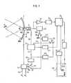
- a main transducer 1is shown in the form of a spherical cap supported by a mounting which allows it to move along three orthogonal axes X, Y and Z.
- This mountinghas been represented schematically, its realization being at the reach of the skilled person.
- an auxiliary transducer 2of generally cylindrical shape, which passes through the cap 1 and is fixed to it.
- a pocket of water Pis interposed between the cap 1 and the surface S of the patient's body, the latter being assumed to be lying on a horizontal plane.
- the cap 1is for example 200 to 300 mm in diameter and is composed of a large number (300 or 400) of piezoelectric elements 10, 11, etc ... ( Figure 1) isolated from each other and juxtaposed to form a mosaic. These elements are metallized on their two faces, one of the metallizations being connected to ground and the other to excitation connections by a main emitter 3.
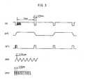
- the latterprovides an electrical signal A (FIG. 3) composed of high frequency wave trains (500 KHz for example) of relatively low peak power (ten or one hundred watts for example), but of relatively long duration (for example of the order of a second) separated by time intervals of the order of 1/10 sec., time necessary for the formation of an image by the ultrasound device.
- Aelectrical signal A
- Such a regimecan be obtained by means of transmitters using power transistors.
- the elements of the transducer 1will be divided into groups each excited by a separate transmitter (the rectangle 4 symbolizing the set of these transmitters), the elements of each group being distributed in the same circular area of the spherical surface.
- the focal spot formed in the center of the spheremay, with this technique, be very small (diameter of 2 or 3 mm for example) and have a strictly fixed position for a given position of the transducer.
- the auxiliary transducer 2is itself connected, on the one hand, to a transmitter 21 of high frequency electrical pulses, on the other hand, to a reception amplifier 22 followed by a analog-digital converter 23, itself followed by a memory 24.
- the transmitter 21is synchronized by a pulse generator 211 which supplies 256 pulses during each of the successive time intervals of 1/10 of a second. Each of these time intervals corresponds to a complete scanning of a predetermined angular sector 6 (FIG. 1) by the beam emitted by the transducer 2, therefore the formation, in the scanning plane, of an image of the area observed by the ultrasound device.
- the transducer 2is advantageously of the type described in French patent applications No 80 16717 filed on July 29, 1980 for: "Sectorial scanning ultrasound probe comprising two coupling liquids" and No 80 16718 filed on July 29, 1980 for: " Mechanical sectoral scanning ultrasound probe ", that is to say that it comprises an oscillating pieco-electric element 200 controlled by a motor 201, itself controlled by an electronic circuit which has been symbolized by a rectangle 4.
- This electronic circuitprovides control signals for the motor 201 housed inside the transducer housing and is arranged so that a complete oscillation of the motor corresponds to the duration of formation of an image defined above ( 1/10 sec.).
- the switch 210In a first operating mode (processing and control) the switch 210 is in position I as well as the switches 212 and 33.
- the generator 211is synchronized by a first output 41 of the circuit 4, and this is then adjusted, by means not shown, to generate, on its output 43 connected to the engine 201, signals having the waveform (MT) represented in FIG. 4.
- the scanning of an imageis therefore carried out in 1/10 s and is followed by a time interval of 1 s during which the oscillating element 200 remains stationary, so that the transducer 2 does not receive echoes.
- a circuit 34During the intervals between the scanning periods, a circuit 34 generates slots of 1 s which are used to synchronize the transmitter 3, while, during the scanning periods, a circuit 213 generates slots of 1/10 s which serve to synchronize generator 211.
- the transducer 1generates a beam of ultrasound in quasi-continuous regime, while the ultrasound device forms an image every second in the intervals between the wave trains.
- the waveform of the signals then emitted by the generator 211is shown in (BT).
- the switch 210In a second operating mode (marking), the switch 210 remaining in position I, the switch 33 is in position 11, so that the transmitter 3 is not synchronized and that the focused ultrasound beam is not emitted .
- the switch 212is also in position II, so that the generator 211 is synchronized by a second output 42 of the circuit 4 and this is adjusted to generate, on its output 43, signals having the waveform (MR) shown in Figure 3.
- the scans of 1/10 sare therefore separated by time intervals of 1/100 sec. only and the images are formed from the echoes coming from the reflection of the pulses generated by the transducer 2.
- the generator 211supplies the signals (BR).
- the switch 210In a third mode of operation (control of the focal region), the switch 210 is in position III, so that the transmitter 21 and the transducer 2 do not transmit.
- the switch 212is still in position II, so that the generator 211 is synchronized by the output 42 of the circuit 4, and the latter is adjusted as in the second operating mode, so that the scans of 1/10 s are still separated by intervals of 1/100 sec.
- the switch 33is in position III and, consequently, the transmitter 3 is now synchronized by the generator 211 which then supplies the signals (BR).
- the ultrasound devicetherefore consists of the transmitter 3, the transducer 1 operating on transmission and the transducer 2 operating on reception. As a result, an image of the energy concentration zone in the focal region emitted by the transducer 1 is obtained.
- the echographic signals received at 22 in the first or third operating modesare, after analog-digital conversion at 23, stored line by line in memory 24, a write addressing device 25, controlled by circuit 4, allowing the respective angles of deflection of the beam emitted and / or received by the transducer 2 to correspond to the respective lines of the memory.
- a device 26 for rapid reading of the memoryexcites the X and Y deflection coils of a cathode ray tube 28, therefore the brightness control electrode receives the corresponding content from the memory 24, transformed into an analog signal by a converter digital-analog 27.
- control circuit 4could for example comprise a monovibrator providing slots of duration adjustable to 1/100 s or 1 s. according to the operating mode and the circuits for generating increasing and decreasing voltages of duration 1/10 s., triggered by said slots.
- the deviceprovides only one image per second, but this rate is sufficient to allow an almost permanent verification of the position of the focal spot.
Landscapes
- Health & Medical Sciences (AREA)
- Engineering & Computer Science (AREA)
- Physics & Mathematics (AREA)
- Life Sciences & Earth Sciences (AREA)
- Remote Sensing (AREA)
- Radar, Positioning & Navigation (AREA)
- Radiology & Medical Imaging (AREA)
- General Health & Medical Sciences (AREA)
- Biomedical Technology (AREA)
- Nuclear Medicine, Radiotherapy & Molecular Imaging (AREA)
- Acoustics & Sound (AREA)
- Veterinary Medicine (AREA)
- Public Health (AREA)
- Animal Behavior & Ethology (AREA)
- Molecular Biology (AREA)
- Surgery (AREA)
- Pathology (AREA)
- Medical Informatics (AREA)
- Heart & Thoracic Surgery (AREA)
- Biophysics (AREA)
- Computer Networks & Wireless Communication (AREA)
- General Physics & Mathematics (AREA)
- Thermotherapy And Cooling Therapy Devices (AREA)
- Surgical Instruments (AREA)
- Ultra Sonic Daignosis Equipment (AREA)
Description
Translated fromFrenchLes appareils d'échographie classiques permettant évidemment de procéder à l'examen de tumeurs à l'intérieur du corps en en formant une image sur l'écran d'un tube cathodique.Conventional ultrasound devices obviously allow the examination of tumors inside the body by forming an image on the screen of a cathode ray tube.
On sait par ailleurs qu'il est possible d'obtenir une destruction des cellules-en particulier des cellules malignes-en les soumettent de façon plus ou moins prolongée à une élévation de température. Les cellules à détruire doivent par exemple être portées à environ 45°C et ce, de manière bien contrôlée, en évitant d'atteindre des températures excessives qui pourraient provoquer des brûlures graves autour de la lésion. Le problème technique à résoudre consiste donc à la fois à maîtriser la quantité d'énergie et sa localisation.We also know that it is possible to obtain the destruction of cells - in particular malignant cells - by subjecting them more or less prolonged to a rise in temperature. The cells to be destroyed must, for example, be brought to around 45 ° C. in a well-controlled manner, avoiding reaching excessive temperatures which could cause serious burns around the lesion. The technical problem to be solved therefore consists in both controlling the amount of energy and its location.
Les différents procédés antérieurs (emploi d'hyperfréquences, de rayonnement infra-rouge, et autres) permettent de traiter des tumeurs superficielles, mais non d'atteindre des tissus plus profonds.The various prior procedures (use of microwave frequencies, infrared radiation, and the like) make it possible to treat superficial tumors, but not to reach deeper tissues.
Selon EP-A-68 961 un dispositif d'hyperthermie combine un générateur d'un faisceau focalisé d'ultrasons comportant un émetteur principal d'ondes électriques à haute fréquence et un transducteur piézo-électrique principal, à un dispositif d'échographie comprenant un générateur auxiliaire d'impulsions électriques à haute fréquence associé à un transducteur piézo-électrique auxiliaire et à des moyens de formation d'images de la zone à traiter.According to EP-A-68 961 a hyperthermia device combines a generator of a focused beam of ultrasound comprising a main transmitter of high frequency electric waves and a main piezoelectric transducer, with an ultrasound device comprising a auxiliary generator of high frequency electrical pulses associated with an auxiliary piezoelectric transducer and with means for forming images of the area to be treated.
Ce brevet ne prévoit pas d'interrompre l'émission principale pour pouvoir effectuer l'échographie pendant le traitement lui-même.This patent does not intend to interrupt the main emission in order to be able to carry out the ultrasound during the treatment itself.
Par ailleurs, la focalisation du faisceau principal y est obtenue par déphasage électronique, et aucun balayage échographique n'est prévu.Furthermore, the focusing of the main beam is obtained there by electronic phase shift, and no ultrasound scanning is planned.
L'invention propose de réaliser un appareil qui conjugue les trois fonctions de localisation de la zone à traiter, de traitement par élévation de température bien maîtrisée dans une région restreinte bien délimitée à l'intérieur de cette zone et de contrôle simultané des résultats du traitement.The invention proposes to produce an apparatus which combines the three functions of localization of the area to be treated, of treatment by elevation of temperature well controlled in a restricted region well delimited within this area and of simultaneous control of the results of the treatment. .
A cet effet, l'invention de caractérisé par les caractéristiques de la seconde partie de la revendication 1.To this end, the invention characterized by the characteristics of the second part of
On notera que l'utilisation d'un transducteur à surface focalisante était connue en soi selon ULTRASONICS, vol. 5, avril 1967, figure 1c, tandis que le balayage échographique d'une zone à traiter était également connu en soi selon MESURES REGULATION AUTOMATISME, vol. 45, février 1980.It will be noted that the use of a focusing surface transducer was known per se according to ULTRASONICS, vol. 5, April 1967, FIG. 1c, while the ultrasound scanning of an area to be treated was also known per se according to MESURES REGULATION AUTOMATISME, vol. 45, February 1980.
Il résulte de la revendication 4 que, pendant les modes auxiliaires de fonctionnement, destinés à effectuer des réglages précis, la qualité de l'image échographique, soit de la zone à traiter (mode de repérage), soit de la région focale (mode de contrôle de la région restreinte), sera sensiblement meilleure que pendant le mode de traitement, pendant lequel les images successives de la zone à traiter se succéderont par exemple à des intervalles de l'ordre de la seconde, ce qui permettra toutefois de vérifier de manière satisfaisante la position de la région focale pendant le traitement.It follows from claim 4 that, during the auxiliary operating modes, intended to make precise adjustments, the quality of the ultrasound image, either of the area to be treated (tracking mode), or of the focal region (mode of control of the restricted region), will be appreciably better than during the processing mode, during which the successive images of the area to be treated will follow one another at intervals of the order of a second, which will however make it possible to verify in a manner the position of the focal region during treatment is satisfactory.
Suivant une forme d'exécution préférée, le transducteur principal est constitué par une mosaïque d'éléments piézo-électriques isolés les uns des autres et formant une calotte sphérique associée à des moyens de contrôler son déplacement suivant trois axes orthogonaux, tandis que le transducteur auxiliaire est solidarisé au sommet de ladite calotte et associé à des moyens d'effectuer un balayage sectoriel dans un plan qui passe par l'axe de symétrie de ladite calotte.According to a preferred embodiment, the main transducer is constituted by a mosaic of piezoelectric elements isolated from each other and forming a spherical cap associated with means of controlling its movement along three orthogonal axes, while the auxiliary transducer is secured to the top of said cap and associated with means for performing a sector sweep in a plane which passes through the axis of symmetry of said cap.
D'autres particularités, ainsi que les avantages de l'invention, apparaîtront clairement à la lumière de la description ci-après.Other features, as well as the advantages of the invention, will become apparent in the light of the description below.
Au dessin annexé:
- La figure 1 est le schéma de principe d'un appareil d'hyperthermie conforme à un mode d'exécution préféré de l'invention;
- La figure 2 représente schématiquement, en perspective, le transducteur principal et son dispositif de support mobile;
- La figure 3 représente les formes d'ondes en différents points des circuits de l'appareil; et
- La figure 4 illustre l'image obtenue sur l'écran de visualisation que comporte l'appareil.
- Figure 1 is the block diagram of a hyperthermia device according to a preferred embodiment of the invention;
- FIG. 2 schematically represents, in perspective, the main transducer and its mobile support device;
- Figure 3 shows the waveforms at different points on the device circuits; and
- FIG. 4 illustrates the image obtained on the display screen that the device includes.
A la figure 2, on a représenté un transducteur principal 1 en forme de calotte sphérique supporté par un montage qui en permet les déplacements suivant trois axes orthogonaux X, Y et Z. Cet montage a été représenté de manière schématique, sa réalisation étant à la portée de l'homme du métier. Suivant l'axe de la calotte sphérique est disposé un transducteur auxiliaire 2 de forme générale cylindrique, qui passe à travers la calotte 1 et lui est fixé. Une poche d'eau P est interposée entre la calotte 1 et la surface S du corps du patient, celui-ci étant supposé allongé sur un plan horizontal.In FIG. 2, a
La calotte 1 a par exemple 200 à 300 mm de diamètre et est composée d'un grand nombre (300 ou 400) d'éléments piézo-électriques 10, 11, etc... (figure 1) isolés les uns des autres et juxtaposés pour constituer une mosaïque. Ces éléments sont métallisés sur leurs deux faces, l'une des métallisations étant reliée à la masse et l'autre à des connexions d'excitation par un émetteur principal 3.The
Ce dernier fournit un signal électrique A (figure 3) composé de trains d'ondes à haute fréquence (500 KHz par exemple) de puissance de crête relativement faible (une dizaine ou une centaine de watts par exemple), mais de durée relativement grande (par exemple de l'ordre de la seconde) séparés par des intervalles de temps de l'ordre de 1/10 sec., temps nécessaire pour la formation d'une image par le dispositif d'échographie. Il s'agit donc d'un régime d'émission quasi-continu, destiné au traitement. Un tel régime peut être obtenu au moyen d'émetteurs utilisant des transistors de puissance. De préférence, les éléments du transducteur 1 seront répartis en groupes excités chacun par un émetteur séparé (le rectangle 4 symbolisant l'ensemble de ces émetteurs), les éléments de chaque groupe étant répartis dans une même zone circulaire de la surface sphérique. En réglant les phases relatives des émissions, il est possible de modifier la répartition de l'énergie dans la région de focalisation du faisceau ultrasonore.The latter provides an electrical signal A (FIG. 3) composed of high frequency wave trains (500 KHz for example) of relatively low peak power (ten or one hundred watts for example), but of relatively long duration ( for example of the order of a second) separated by time intervals of the order of 1/10 sec., time necessary for the formation of an image by the ultrasound device. It is therefore a quasi-continuous emission regime, intended for processing. Such a regime can be obtained by means of transmitters using power transistors. Preferably, the elements of the
On a symbolisé par une entrée 31 de l'émetteur 3 un réglage de la puissance émise et par une entrée 32 un réglage de la durée des trains d'ondes. La tache focale formée au centre de la sphère pourra, avec cette technique, être très petite (diamètre de 2 ou 3 mm par exemple) et avoir une position rigoureusement fixe pour une position donnée du transducteur.There has been symbolized by an
A la figure 1, on voit que le transducteur auxiliaire 2 est lui-même relié, d'une part, à un émetteur 21 d'impulsions électriques à haute fréquence, d'autre part, à un amplificateur de réception 22 suivi d'un convertisseur analogique-numérique 23, lui-même suivi d'une mémoire 24. L'émetteur 21 est synchronisé par un générateur d'impulsions 211 qui fournit 256 impulsions pendant chacun des intervalles detemps successifs de 1/10 de seconde. A chacun de ces intervalles de temps correspond un balayage complet d'un secteur angulaire prédéterminé 6 (figure 1) par le faisceau émis par le transducteur 2, donc la formation, dans le plan de balayage, d'une image de la zone observée par le dispositif d'échographie.In FIG. 1, it can be seen that the
Le transducteur 2 est avantageusement du type décrit dans les demandes de brevet français No 80 16717 déposée le 29 Juillet 1980 pour: "Sonde d'échographie à balayage sectoriel comportant deux liquides de couplage" et No 80 16718 déposée le 29 Juillet 1980 pour: "Sonde d'échographie à balayage sectoriel mécanique", c'est-à-dire qu'il comporte un élément piéco-électrique oscillant 200 commandé par un moteur 201, lui-même commandé par un circuit électronique que l'on a symbolisé par un rectangle 4. Ce circuit électronique fournit des signaux de commande du moteur 201 logé à l'intérieur du boîtier du transducteur et est agencé de façon qu'une oscillation complète du moteur corresponde à la durée de formation d'une image définie ci-dessus (1/10 sec.).The
Dans un premier mode de fonctionnement (traitement et contrôle) le commutateur 210 est en position I ainsi que les commutateurs 212 et 33.In a first operating mode (processing and control) the
Dans la position I des commutateurs 33 et 212, le générateur 211 est synchronisé par une première sortie 41 du circuit 4, et celui-ci est alors réglé, par des moyens non figurés, pour engendrer, sur sa sortie 43 reliée au moteur 201, des signaux ayant la forme d'onde (MT) représentée à la figure 4. Le balayage d'une image s'effectue donc en 1/10 s et est suivi d'un intervalle de temps de 1 s pendant lequel l'élément oscillant 200 reste immobile, si bien que le transducteur 2 ne reçoit pas d'échos.In position I of
Pendant les intervalles entre les périodes de balayage, un circuit 34 engendre des créneaux de 1 s qui servent à synchroniser l'émetteur 3, tandis que, pendant les périodes de balayage, un circuit 213 engendre des créneaux de 1/10 s qui servent à synchroniser le générateur 211.During the intervals between the scanning periods, a
Ainsi, dans ce mode de fonctionnement, le transducteur 1 engendre un faisceau d'ultrasons en régime quasi-continu, tandis que le dispositif d'échographie forme une image toutes les secondes dans les intervalles entre les trains d'ondes. On a représenté en (BT) la forme d'ondes des signaux alors émis par le générateur 211.Thus, in this operating mode, the
Dans un second mode de fonctionnement (repérage) le commutateur 210 restant en position I, le commutateur 33 est en position 11, si bien que l'émetteur 3 n'est pas synchronisé et que le faisceau d'ultrasons focalisé n'est pas émis. Le commutateur 212 est également en position II, si bien que le générateur 211 est synchronisé par une deuxième sortie 42 du circuit 4 et celui-ci est réglé pour engendrer, sur sa sortie 43, des signaux ayant la forme d'onde (MR) représentée à la figure 3. Les balayages de 1/10 s sont donc séparés par des intervalles de temps de 1/100 sec. seulement et les images sont formées à partir des échos provenant de la réflexion des impulsions engendrées par le transducteur 2. Le générateur 211 fournit les signaux (BR).In a second operating mode (marking), the
Dans un troisième mode de fonctionnement (contrôle de la région focale), le commutateur 210 est en position III, si bien que l'émetteur 21 et le transducteur 2 n'émettent pas. Le commutateur 212 est encore en position II, si bien que le générateur 211 est synchronisé par la sortie 42 du circuit 4, et ce dernier est réglé comme dans le second mode de fonctionnement, si bien que les balayages de 1/10 s sont encore séparés par des intervalles de 1/100 sec. Le commutateur33 est en position III et, par conséquent, l'émetteur 3 est maintenant synchronisé par le générateur 211 qui fournit alors les signaux (BR).In a third mode of operation (control of the focal region), the
Dans ce troisième mode de fonctionnement, le dispositif échographique est donc constitué par l'émetteur 3, le transducteur 1 fonctionnant à l'émission et le transducteur 2 fonctionnant à la réception. Il en résulte qu'une image de la zone de concentration de l'énergie dans la région focale émise par le transducteur 1 est obtenue.In this third operating mode, the ultrasound device therefore consists of the
Les signaux échographiques reçus en 22 dans le premier ou le troisième modes de fonctionnement sont, après conversion analogique-numérique en 23, stockés ligne par ligne dans la mémoire 24, un dispositif d'adressage d'écriture 25, commandé par le circuit 4, permettant de faire correspondre les angles respectifs de déviation du faisceau émis et/ou reçu par le transducteur 2 aux lignes respectives de la mémoire. Un dispositif 26 de lecture rapide de la mémoire excite les bobines de déviation en X et en Y d'un tube cathodique 28, donc l'électrode de commande de brillance reçoit le contenu correspondant de la mémoire 24, transformé en signal analogique par un convertisseur numérique-analogique 27.The echographic signals received at 22 in the first or third operating modes are, after analog-digital conversion at 23, stored line by line in memory 24, a write
La réalisation pratique detous les circuits décrits et représentés est à la portée de l'homme de l'Art. Le circuit de commande 4 pourra par exemple comporter un monovibrateur fournissant des créneaux de durée réglable à 1/100 s ou 1 s. suivant le mode de fonctionnement et des circuits de génération de tensions croissantes et décroissantes de durée 1/10 s., déclenchés par lesdits créneaux.The practical realization of all the circuits described and represented is within the reach of those skilled in the art. The control circuit 4 could for example comprise a monovibrator providing slots of duration adjustable to 1/100 s or 1 s. according to the operating mode and the circuits for generating increasing and decreasing voltages of
L'appareil qui vient d'être décrit fonctionne de la manière suivante:
- Dans le mode de fonctionnement en repérage, l'opérateur recherche et localise la zone à traiter. Le dispositif de visualisation est agencé, de manière connue en soi, pour matérialiser sur l'écran du tube cathodique (par exemple par une croix) la position théorique de la tache focale dans le plan de coupe représenté, plan qui passe par l'axe de symétrie du transducteur 1. (Il s'agit d'échographie du type B). L'opérateur commence par déplacer le transducteur 1 en X, jusqu'à ce que la tumeur apparaisse nettement sur l'écran, puis il le déplace en Y et Z, jusqu'à ce que la croix coïncide avec la région centrale de l'image de la tumeur (K, figure 4). A ce moment, les commutateurs peuvent être mis en position de contrôle de la région focale: seule celle-ci est alors rendue visible sur l'écran, avec une luminosité proportionnelle à la concentration d'énergie correspondante. On a ainsi une représentation de ce que sera la répartition de l'énergie de l'onde de traitement, ce qui permet de contrôler et de parfaire les réglages.
- In the tracking operation mode, the operator searches for and locates the area to be treated. The display device is arranged, in a manner known per se, to materialize on the screen of the cathode ray tube (for example by a cross) the theoretical position of the focal spot in the section plane shown, plane which passes through the axis symmetry of
transducer 1. (This is type B ultrasound). The operator starts by moving thetransducer 1 in X, until the tumor appears clearly on the screen, then he moves it in Y and Z, until the cross coincides with the central region of the image of the tumor (K, Figure 4). At this time, the switches can be put in the focal region control position: only this is then made visible on the screen, with a brightness proportional to the corresponding energy concentration. We thus have a representation of what will be the distribution of the energy of the processing wave, which makes it possible to control and perfect the adjustments.
Pendant le traitement, l'appareil ne fournit qu'une image par seconde, mais cette cadence est suffisante pour permettre une vérification quasi permanente de la position de la tache focale.During the treatment, the device provides only one image per second, but this rate is sufficient to allow an almost permanent verification of the position of the focal spot.
Il est clair que l'appareil décrit permet le contrôle de l'évolution de la tumeur après chaque séquence de traitement.It is clear that the device described makes it possible to monitor the progress of the tumor after each treatment sequence.
Claims (5)
Applications Claiming Priority (2)
| Application Number | Priority Date | Filing Date | Title |
|---|---|---|---|
| FR8406877 | 1984-05-03 | ||
| FR8406877AFR2563725B1 (en) | 1984-05-03 | 1984-05-03 | APPARATUS FOR EXAMINING AND LOCATING ULTRASONIC TUMORS WITH A LOCALIZED HYPERTHERMAL TREATMENT DEVICE |
Related Child Applications (1)
| Application Number | Title | Priority Date | Filing Date |
|---|---|---|---|
| EP89112085ADivision-IntoEP0339693B1 (en) | 1984-05-03 | 1985-03-25 | Ultrasonic device for examining and locating tumours provided with a device for localized hyperthermia treatment |
Publications (2)
| Publication Number | Publication Date |
|---|---|
| EP0162735A1 EP0162735A1 (en) | 1985-11-27 |
| EP0162735B1true EP0162735B1 (en) | 1990-11-28 |
Family
ID=9303660
Family Applications (2)
| Application Number | Title | Priority Date | Filing Date |
|---|---|---|---|
| EP85400574AExpired - LifetimeEP0162735B1 (en) | 1984-05-03 | 1985-03-25 | Ultrasonic device for examining and locating tumours provided with a device for localized hyperthermy treatment |
| EP89112085AExpired - LifetimeEP0339693B1 (en) | 1984-05-03 | 1985-03-25 | Ultrasonic device for examining and locating tumours provided with a device for localized hyperthermia treatment |
Family Applications After (1)
| Application Number | Title | Priority Date | Filing Date |
|---|---|---|---|
| EP89112085AExpired - LifetimeEP0339693B1 (en) | 1984-05-03 | 1985-03-25 | Ultrasonic device for examining and locating tumours provided with a device for localized hyperthermia treatment |
Country Status (6)
| Country | Link |
|---|---|
| US (1) | US4658828A (en) |
| EP (2) | EP0162735B1 (en) |
| JP (1) | JPS60241436A (en) |
| BR (1) | BR8502055A (en) |
| DE (2) | DE3585691D1 (en) |
| FR (1) | FR2563725B1 (en) |
Families Citing this family (167)
| Publication number | Priority date | Publication date | Assignee | Title |
|---|---|---|---|---|
| FR2563725B1 (en)* | 1984-05-03 | 1988-07-15 | Dory Jacques | APPARATUS FOR EXAMINING AND LOCATING ULTRASONIC TUMORS WITH A LOCALIZED HYPERTHERMAL TREATMENT DEVICE |
| US5150712A (en)* | 1983-12-14 | 1992-09-29 | Edap International, S.A. | Apparatus for examining and localizing tumors using ultra sounds, comprising a device for localized hyperthermia treatment |
| US5143073A (en)* | 1983-12-14 | 1992-09-01 | Edap International, S.A. | Wave apparatus system |
| FR2664819B1 (en)* | 1990-07-23 | 1994-04-29 | Edap Int | ULTRA-FAST EXTRACORPOREAL ULTRASONIC HYPERTHERMAL APPARATUS. |
| JPS6113955A (en)* | 1984-06-30 | 1986-01-22 | 株式会社東芝 | Ultrasonic therapy device |
| JPS6113954A (en)* | 1984-06-30 | 1986-01-22 | 株式会社東芝 | Ultrasonic therapy device |
| US5431621A (en)* | 1984-11-26 | 1995-07-11 | Edap International | Process and device of an anatomic anomaly by means of elastic waves, with tracking of the target and automatic triggering of the shootings |
| DE3536144A1 (en)* | 1985-10-10 | 1987-04-16 | Philips Patentverwaltung | METHOD FOR ULTRASONIC CONTROL IN STONE SHREDDING AND ARRANGEMENT FOR IMPLEMENTING THE METHOD |
| GB8529446D0 (en)* | 1985-11-29 | 1986-01-08 | Univ Aberdeen | Divergent ultrasound arrays |
| DE3543867C3 (en)* | 1985-12-12 | 1994-10-06 | Wolf Gmbh Richard | Device for the spatial location and destruction of concrements in body cavities |
| DE3607949A1 (en)* | 1986-03-11 | 1987-09-17 | Wolf Gmbh Richard | METHOD FOR DETECTING POSSIBLE TISSUE DAMAGE IN THE MEDICAL APPLICATION OF HIGH-ENERGY SOUND |
| JPH0817779B2 (en)* | 1986-03-31 | 1996-02-28 | 株式会社東芝 | Biomedical equipment |
| DE3612151A1 (en)* | 1986-04-10 | 1987-12-23 | Wolf Gmbh Richard | BEARING SYSTEM FOR DETERMINING THE POSITION OF REFLECTIVE BORDER LAYERS IN THE HUMAN BODY |
| JPS6346147A (en)* | 1986-04-24 | 1988-02-27 | 株式会社東芝 | Ultrasonic remedy apparatus |
| US4875487A (en)* | 1986-05-02 | 1989-10-24 | Varian Associates, Inc. | Compressional wave hyperthermia treating method and apparatus |
| US4803995A (en)* | 1986-06-27 | 1989-02-14 | Kabushiki Kaisha Toshiba | Ultrasonic lithotrity apparatus |
| JP2621143B2 (en)* | 1986-08-30 | 1997-06-18 | 株式会社島津製作所 | Hyperthermia device |
| DE3853641D1 (en)* | 1987-02-16 | 1995-06-01 | Siemens Ag | Sound generator for treating a living being with focused sound waves. |
| US4907573A (en)* | 1987-03-21 | 1990-03-13 | Olympus Optical Co., Ltd. | Ultrasonic lithotresis apparatus |
| FR2614722B1 (en)* | 1987-04-28 | 1992-04-17 | Dory Jacques | ACOUSTIC FILTER FOR SUPPRESSING OR MITIGATING NEGATIVE ALTERNATIONS OF AN ELASTIC WAVE AND ELASTIC WAVE GENERATOR COMPRISING SUCH A FILTER |
| FR2614747B1 (en)* | 1987-04-28 | 1989-07-28 | Dory Jacques | ELASTIC PULSE GENERATOR HAVING A PREDETERMINED WAVEFORM AND ITS APPLICATION TO TREATMENT OR MEDICAL DIAGNOSIS |
| FR2619003B1 (en)* | 1987-08-05 | 1997-06-27 | Toshiba Kk | ULTRASONIC THERAPEUTIC TREATMENT APPARATUS |
| US4809677A (en)* | 1987-09-14 | 1989-03-07 | The Boc Group, Inc. | Heater traverse mechanism for infant care center |
| DE8717504U1 (en)* | 1987-10-19 | 1989-01-05 | Siemens AG, 1000 Berlin und 8000 München | Shock wave source with central ultrasound location system |
| US4819650A (en)* | 1987-10-30 | 1989-04-11 | Wayne State University | Biplane probe including centerline highlighting |
| US4932414A (en)* | 1987-11-02 | 1990-06-12 | Cornell Research Foundation, Inc. | System of therapeutic ultrasound and real-time ultrasonic scanning |
| US5143063A (en)* | 1988-02-09 | 1992-09-01 | Fellner Donald G | Method of removing adipose tissue from the body |
| FR2627375A1 (en)* | 1988-02-19 | 1989-08-25 | Norris Oliver | Multifunctional echograph detector and ultrasonic device - uses Doppler probe to locate tumours and by hand moulding output of several ultrasonic transducers is focussed |
| US4951653A (en)* | 1988-03-02 | 1990-08-28 | Laboratory Equipment, Corp. | Ultrasound brain lesioning system |
| DE3817726A1 (en)* | 1988-05-25 | 1989-11-30 | Siemens Ag | DEVICE FOR SPACIOUS ULTRASONIC LOCATION OF CONCRETE |
| US4960109A (en)* | 1988-06-21 | 1990-10-02 | Massachusetts Institute Of Technology | Multi-purpose temperature sensing probe for hyperthermia therapy |
| US4938217A (en)* | 1988-06-21 | 1990-07-03 | Massachusetts Institute Of Technology | Electronically-controlled variable focus ultrasound hyperthermia system |
| EP0355178B1 (en)* | 1988-08-17 | 1993-11-18 | Siemens Aktiengesellschaft | Apparatus for the contactless desintegration of concrements in a living thing body |
| DE68922387T2 (en)* | 1989-02-28 | 1995-10-26 | Toshiba Kawasaki Kk | Device and method for crushing concrements. |
| US5435311A (en)* | 1989-06-27 | 1995-07-25 | Hitachi, Ltd. | Ultrasound therapeutic system |
| US4945898A (en)* | 1989-07-12 | 1990-08-07 | Diasonics, Inc. | Power supply |
| US5065761A (en)* | 1989-07-12 | 1991-11-19 | Diasonics, Inc. | Lithotripsy system |
| US6551576B1 (en) | 1989-12-22 | 2003-04-22 | Bristol-Myers Squibb Medical Imaging, Inc. | Container with multi-phase composition for use in diagnostic and therapeutic applications |
| US5149319A (en)* | 1990-09-11 | 1992-09-22 | Unger Evan C | Methods for providing localized therapeutic heat to biological tissues and fluids |
| US5776429A (en)* | 1989-12-22 | 1998-07-07 | Imarx Pharmaceutical Corp. | Method of preparing gas-filled microspheres using a lyophilized lipids |
| US5228446A (en)* | 1989-12-22 | 1993-07-20 | Unger Evan C | Gas filled liposomes and their use as ultrasonic contrast agents |
| US5585112A (en)* | 1989-12-22 | 1996-12-17 | Imarx Pharmaceutical Corp. | Method of preparing gas and gaseous precursor-filled microspheres |
| US5352435A (en)* | 1989-12-22 | 1994-10-04 | Unger Evan C | Ionophore containing liposomes for ultrasound imaging |
| US5542935A (en) | 1989-12-22 | 1996-08-06 | Imarx Pharmaceutical Corp. | Therapeutic delivery systems related applications |
| US5469854A (en)* | 1989-12-22 | 1995-11-28 | Imarx Pharmaceutical Corp. | Methods of preparing gas-filled liposomes |
| US5922304A (en)* | 1989-12-22 | 1999-07-13 | Imarx Pharmaceutical Corp. | Gaseous precursor filled microspheres as magnetic resonance imaging contrast agents |
| US5733572A (en)* | 1989-12-22 | 1998-03-31 | Imarx Pharmaceutical Corp. | Gas and gaseous precursor filled microspheres as topical and subcutaneous delivery vehicles |
| US5209720A (en)* | 1989-12-22 | 1993-05-11 | Unger Evan C | Methods for providing localized therapeutic heat to biological tissues and fluids using gas filled liposomes |
| US5656211A (en)* | 1989-12-22 | 1997-08-12 | Imarx Pharmaceutical Corp. | Apparatus and method for making gas-filled vesicles of optimal size |
| US6146657A (en)* | 1989-12-22 | 2000-11-14 | Imarx Pharmaceutical Corp. | Gas-filled lipid spheres for use in diagnostic and therapeutic applications |
| US5705187A (en)* | 1989-12-22 | 1998-01-06 | Imarx Pharmaceutical Corp. | Compositions of lipids and stabilizing materials |
| US5580575A (en)* | 1989-12-22 | 1996-12-03 | Imarx Pharmaceutical Corp. | Therapeutic drug delivery systems |
| US5773024A (en)* | 1989-12-22 | 1998-06-30 | Imarx Pharmaceutical Corp. | Container with multi-phase composition for use in diagnostic and therapeutic applications |
| US5305757A (en)* | 1989-12-22 | 1994-04-26 | Unger Evan C | Gas filled liposomes and their use as ultrasonic contrast agents |
| US6088613A (en) | 1989-12-22 | 2000-07-11 | Imarx Pharmaceutical Corp. | Method of magnetic resonance focused surgical and therapeutic ultrasound |
| US6001335A (en)* | 1989-12-22 | 1999-12-14 | Imarx Pharmaceutical Corp. | Contrasting agents for ultrasonic imaging and methods for preparing the same |
| US20020150539A1 (en)* | 1989-12-22 | 2002-10-17 | Unger Evan C. | Ultrasound imaging and treatment |
| DE69123864T2 (en)* | 1990-03-24 | 1997-08-14 | Toshiba Kawasaki Kk | Device for medical treatment with ultrasound waves |
| JP2950582B2 (en)* | 1990-05-31 | 1999-09-20 | 株式会社東芝 | Stone crushing equipment |
| US5205290A (en) | 1991-04-05 | 1993-04-27 | Unger Evan C | Low density microspheres and their use as contrast agents for computed tomography |
| US5874062A (en)* | 1991-04-05 | 1999-02-23 | Imarx Pharmaceutical Corp. | Methods of computed tomography using perfluorocarbon gaseous filled microspheres as contrast agents |
| US5233994A (en)* | 1991-05-13 | 1993-08-10 | Advanced Technology Laboratories, Inc. | Detection of tissue abnormality through blood perfusion differentiation |
| US5291890A (en)* | 1991-08-29 | 1994-03-08 | General Electric Company | Magnetic resonance surgery using heat waves produced with focussed ultrasound |
| US5325860A (en)* | 1991-11-08 | 1994-07-05 | Mayo Foundation For Medical Education And Research | Ultrasonic and interventional catheter and method |
| FR2686258B1 (en)* | 1992-01-21 | 1994-09-16 | Edap Int | METHOD FOR VIEWING AN ANATOMICAL TARGET FOR ITS TREATMENT WITH FOCUSED ELASTIC WAVES AND APPARATUS APPLYING THIS PROCESS TO THE TREATMENT OF PROSTATE BY HYPERTHERMIA. |
| US5247935A (en)* | 1992-03-19 | 1993-09-28 | General Electric Company | Magnetic resonance guided focussed ultrasound surgery |
| DE4229817C2 (en)* | 1992-09-07 | 1996-09-12 | Siemens Ag | Method for the non-destructive and / or non-invasive measurement of a temperature change in the interior of a living object in particular |
| DE4302537C1 (en)* | 1993-01-29 | 1994-04-28 | Siemens Ag | Ultrasound imaging and therapy device - generates imaging waves and focussed treatment waves having two differing frequencies for location and treatment of e.g tumours |
| DE4302538C1 (en)* | 1993-01-29 | 1994-04-07 | Siemens Ag | Ultrasonic therapy device for tumour treatment lithotripsy or osteorestoration - with ultrasonic imaging and ultrasonic treatment modes using respective acoustic wave frequencies |
| DE69431741T2 (en)* | 1993-03-12 | 2003-09-11 | Kabushiki Kaisha Toshiba, Kawasaki | Device for medical treatment with ultrasound |
| DE4310923C2 (en)* | 1993-04-02 | 1996-10-31 | Siemens Ag | Therapy device for the treatment of pathological tissue with a catheter |
| US7083572B2 (en)* | 1993-11-30 | 2006-08-01 | Bristol-Myers Squibb Medical Imaging, Inc. | Therapeutic delivery systems |
| JPH07184907A (en) | 1993-12-28 | 1995-07-25 | Toshiba Corp | Ultrasonic therapy equipment |
| AU2373695A (en)* | 1994-05-03 | 1995-11-29 | Board Of Regents, The University Of Texas System | Apparatus and method for noninvasive doppler ultrasound-guided real-time control of tissue damage in thermal therapy |
| US5736121A (en)* | 1994-05-23 | 1998-04-07 | Imarx Pharmaceutical Corp. | Stabilized homogenous suspensions as computed tomography contrast agents |
| US5509896A (en)* | 1994-09-09 | 1996-04-23 | Coraje, Inc. | Enhancement of thrombolysis with external ultrasound |
| US6743779B1 (en) | 1994-11-29 | 2004-06-01 | Imarx Pharmaceutical Corp. | Methods for delivering compounds into a cell |
| US5830430A (en)* | 1995-02-21 | 1998-11-03 | Imarx Pharmaceutical Corp. | Cationic lipids and the use thereof |
| US5984881A (en)* | 1995-03-31 | 1999-11-16 | Kabushiki Kaisha Toshiba | Ultrasound therapeutic apparatus using a therapeutic ultrasonic wave source and an ultrasonic probe |
| US6334846B1 (en) | 1995-03-31 | 2002-01-01 | Kabushiki Kaisha Toshiba | Ultrasound therapeutic apparatus |
| US5558092A (en)* | 1995-06-06 | 1996-09-24 | Imarx Pharmaceutical Corp. | Methods and apparatus for performing diagnostic and therapeutic ultrasound simultaneously |
| US5997898A (en)* | 1995-06-06 | 1999-12-07 | Imarx Pharmaceutical Corp. | Stabilized compositions of fluorinated amphiphiles for methods of therapeutic delivery |
| US6139819A (en)* | 1995-06-07 | 2000-10-31 | Imarx Pharmaceutical Corp. | Targeted contrast agents for diagnostic and therapeutic use |
| US6521211B1 (en) | 1995-06-07 | 2003-02-18 | Bristol-Myers Squibb Medical Imaging, Inc. | Methods of imaging and treatment with targeted compositions |
| US5769879A (en) | 1995-06-07 | 1998-06-23 | Medical Contouring Corporation | Microwave applicator and method of operation |
| US6033645A (en)* | 1996-06-19 | 2000-03-07 | Unger; Evan C. | Methods for diagnostic imaging by regulating the administration rate of a contrast agent |
| US6231834B1 (en) | 1995-06-07 | 2001-05-15 | Imarx Pharmaceutical Corp. | Methods for ultrasound imaging involving the use of a contrast agent and multiple images and processing of same |
| US5730720A (en) | 1995-08-18 | 1998-03-24 | Ip Scientific, Inc. | Perfusion hyperthermia treatment system and method |
| US5895356A (en)* | 1995-11-15 | 1999-04-20 | American Medical Systems, Inc. | Apparatus and method for transurethral focussed ultrasound therapy |
| US5676692A (en)* | 1996-03-28 | 1997-10-14 | Indianapolis Center For Advanced Research, Inc. | Focussed ultrasound tissue treatment method |
| EP0935415B1 (en) | 1996-05-01 | 2006-11-22 | Imarx Pharmaceutical Corp. | In vitro methods for delivering nucleic acids into a cell |
| US6414139B1 (en) | 1996-09-03 | 2002-07-02 | Imarx Therapeutics, Inc. | Silicon amphiphilic compounds and the use thereof |
| JP4139440B2 (en)* | 1996-09-11 | 2008-08-27 | イマアーレクス・フアーマシユーチカル・コーポレーシヨン | Improved method for diagnostic imaging using contrast agents and vasodilators |
| US5846517A (en)* | 1996-09-11 | 1998-12-08 | Imarx Pharmaceutical Corp. | Methods for diagnostic imaging using a renal contrast agent and a vasodilator |
| US5788636A (en)* | 1997-02-25 | 1998-08-04 | Acuson Corporation | Method and system for forming an ultrasound image of a tissue while simultaneously ablating the tissue |
| US6143276A (en)* | 1997-03-21 | 2000-11-07 | Imarx Pharmaceutical Corp. | Methods for delivering bioactive agents to regions of elevated temperatures |
| US6090800A (en)* | 1997-05-06 | 2000-07-18 | Imarx Pharmaceutical Corp. | Lipid soluble steroid prodrugs |
| US6537246B1 (en) | 1997-06-18 | 2003-03-25 | Imarx Therapeutics, Inc. | Oxygen delivery agents and uses for the same |
| US6120751A (en) | 1997-03-21 | 2000-09-19 | Imarx Pharmaceutical Corp. | Charged lipids and uses for the same |
| US7452551B1 (en) | 2000-10-30 | 2008-11-18 | Imarx Therapeutics, Inc. | Targeted compositions for diagnostic and therapeutic use |
| US20050019266A1 (en)* | 1997-05-06 | 2005-01-27 | Unger Evan C. | Novel targeted compositions for diagnostic and therapeutic use |
| US6416740B1 (en) | 1997-05-13 | 2002-07-09 | Bristol-Myers Squibb Medical Imaging, Inc. | Acoustically active drug delivery systems |
| US6548047B1 (en) | 1997-09-15 | 2003-04-15 | Bristol-Myers Squibb Medical Imaging, Inc. | Thermal preactivation of gaseous precursor filled compositions |
| US6123923A (en)* | 1997-12-18 | 2000-09-26 | Imarx Pharmaceutical Corp. | Optoacoustic contrast agents and methods for their use |
| US20010003580A1 (en) | 1998-01-14 | 2001-06-14 | Poh K. Hui | Preparation of a lipid blend and a phospholipid suspension containing the lipid blend |
| CN1058905C (en)* | 1998-01-25 | 2000-11-29 | 重庆海扶(Hifu)技术有限公司 | High-intensity focus supersonic tumor scanning therapy system |
| US6685640B1 (en)* | 1998-03-30 | 2004-02-03 | Focus Surgery, Inc. | Ablation system |
| US6540700B1 (en)* | 1998-10-26 | 2003-04-01 | Kabushiki Kaisha Toshiba | Ultrasound treatment apparatus |
| US7229469B1 (en) | 1999-10-02 | 2007-06-12 | Quantumcor, Inc. | Methods for treating and repairing mitral valve annulus |
| US6409720B1 (en) | 2000-01-19 | 2002-06-25 | Medtronic Xomed, Inc. | Methods of tongue reduction using high intensity focused ultrasound to form an ablated tissue area containing a plurality of lesions |
| US6595934B1 (en) | 2000-01-19 | 2003-07-22 | Medtronic Xomed, Inc. | Methods of skin rejuvenation using high intensity focused ultrasound to form an ablated tissue area containing a plurality of lesions |
| US6413254B1 (en) | 2000-01-19 | 2002-07-02 | Medtronic Xomed, Inc. | Method of tongue reduction by thermal ablation using high intensity focused ultrasound |
| US6692450B1 (en) | 2000-01-19 | 2004-02-17 | Medtronic Xomed, Inc. | Focused ultrasound ablation devices having selectively actuatable ultrasound emitting elements and methods of using the same |
| US8241274B2 (en) | 2000-01-19 | 2012-08-14 | Medtronic, Inc. | Method for guiding a medical device |
| US6361531B1 (en) | 2000-01-21 | 2002-03-26 | Medtronic Xomed, Inc. | Focused ultrasound ablation devices having malleable handle shafts and methods of using the same |
| DE10108799A1 (en)* | 2001-02-19 | 2002-09-05 | Laser & Med Tech Gmbh | Method and device for the ultrasonic vaccination of biological cell material |
| FR2827149B1 (en) | 2001-07-13 | 2003-10-10 | Technomed Medical Systems | FOCUSED ULTRASOUND TREATMENT PROBE |
| US9302087B2 (en) | 2002-02-14 | 2016-04-05 | Gholam A. Peyman | Method and composition for hyperthermally treating cells |
| US8808268B2 (en) | 2002-02-14 | 2014-08-19 | Gholam A. Peyman | Method and composition for hyperthermally treating cells |
| US9233157B2 (en) | 2002-02-14 | 2016-01-12 | Gholam A. Peyman | Method and composition for hyperthermally treating cells |
| US9393396B2 (en) | 2002-02-14 | 2016-07-19 | Gholam A. Peyman | Method and composition for hyperthermally treating cells |
| US8795251B2 (en) | 2002-02-14 | 2014-08-05 | Gholam A. Peyman | Method and composition for hyperthermally treating cells |
| US9289491B2 (en) | 2002-02-14 | 2016-03-22 | Gholam A. Peyman | Method and composition for hyperthermally treating cells |
| US8709488B2 (en) | 2002-02-14 | 2014-04-29 | Gholam A. Peyman | Method and composition for hyperthermally treating cells |
| US8932636B2 (en) | 2002-02-14 | 2015-01-13 | Gholam A. Peyman | Method and composition for hyperthermally treating cells |
| US9320813B2 (en) | 2002-02-14 | 2016-04-26 | Gholam A. Peyman | Method and composition for hyperthermally treating cells |
| US9017729B2 (en) | 2002-02-14 | 2015-04-28 | Gholam A. Peyman | Method and composition for hyperthermally treating cells |
| US8137698B2 (en)* | 2002-02-14 | 2012-03-20 | Peyman Gholam A | Method and composition for hyperthermally treating cells |
| US8119165B2 (en) | 2002-02-14 | 2012-02-21 | Peyman Gholam A | Method and composition for hyperthermally treating cells |
| US8481082B2 (en) | 2002-02-14 | 2013-07-09 | Gholam A. Peyman | Method and composition for hyperthermally treating cells |
| US8668935B2 (en) | 2002-02-14 | 2014-03-11 | Gholam A. Peyman | Method and composition for hyperthermally treating cells |
| US8801690B2 (en) | 2002-02-14 | 2014-08-12 | Gholam A. Peyman | Method and composition for hyperthermally treating cells |
| DE10211886B4 (en)* | 2002-03-18 | 2004-07-15 | Dornier Medtech Gmbh | Method and device for generating bipolar acoustic pulses |
| US7617005B2 (en)* | 2002-04-08 | 2009-11-10 | Ardian, Inc. | Methods and apparatus for thermally-induced renal neuromodulation |
| DE10223196B4 (en)* | 2002-05-24 | 2004-05-13 | Dornier Medtech Systems Gmbh | Method and device for transferring molecules into cells |
| US20040049134A1 (en)* | 2002-07-02 | 2004-03-11 | Tosaya Carol A. | System and methods for treatment of alzheimer's and other deposition-related disorders of the brain |
| US20050020945A1 (en)* | 2002-07-02 | 2005-01-27 | Tosaya Carol A. | Acoustically-aided cerebrospinal-fluid manipulation for neurodegenerative disease therapy |
| US20030191396A1 (en)* | 2003-03-10 | 2003-10-09 | Sanghvi Narendra T | Tissue treatment method and apparatus |
| US7662114B2 (en)* | 2004-03-02 | 2010-02-16 | Focus Surgery, Inc. | Ultrasound phased arrays |
| WO2005107601A2 (en)* | 2004-05-06 | 2005-11-17 | Focus Surgery, Inc. | Method and apparatus for the selective treatment of tissue |
| US20050261571A1 (en)* | 2004-05-21 | 2005-11-24 | Willis Nathaniel P | 3-D ultrasound navigation during radio-frequency ablation |
| US20080194954A1 (en)* | 2004-06-10 | 2008-08-14 | Imarx Therapeutics, Inc. | Ultrasound Device and Method Using Same |
| JP2008516635A (en)* | 2004-10-19 | 2008-05-22 | ザ ガバメント オブ ザ ユナイテッド ステイツ オブ アメリカ, アズ リプレゼンティッド バイ ザ セクレタリー, デパートメント オブ ヘルス アンド ヒューマン サービシーズ, ナショナル イ | Methods and compositions for protecting cells from ultrasound-mediated cytolysis |
| US8364256B2 (en)* | 2004-11-15 | 2013-01-29 | Coraje, Inc. | Method and apparatus of removal of intravascular blockages |
| ATE457722T1 (en)* | 2004-12-15 | 2010-03-15 | Dornier Medtech Systems Gmbh | IMPROVED CELL THERAPY AND TISSUE REGENERATION USING SHOCK WAVES IN PATIENTS WITH CARDIOVASCULAR AND NEUROLOGICAL DISEASES |
| US8038631B1 (en)* | 2005-06-01 | 2011-10-18 | Sanghvi Narendra T | Laparoscopic HIFU probe |
| US20070038096A1 (en)* | 2005-07-06 | 2007-02-15 | Ralf Seip | Method of optimizing an ultrasound transducer |
| US20070010805A1 (en)* | 2005-07-08 | 2007-01-11 | Fedewa Russell J | Method and apparatus for the treatment of tissue |
| DE102005037043C5 (en)* | 2005-08-05 | 2017-12-14 | Dornier Medtech Systems Gmbh | Shock wave therapy device with image acquisition |
| US20080039724A1 (en)* | 2006-08-10 | 2008-02-14 | Ralf Seip | Ultrasound transducer with improved imaging |
| US7559905B2 (en)* | 2006-09-21 | 2009-07-14 | Focus Surgery, Inc. | HIFU probe for treating tissue with in-line degassing of fluid |
| WO2008091655A2 (en)* | 2007-01-23 | 2008-07-31 | The Regents Of The University Of California | Methods, compositions and device for directed and controlled heating and release of agents |
| WO2008137114A1 (en)* | 2007-05-04 | 2008-11-13 | University Of Hawai'i | Methods and compositions for targeted delivery of gene therapeutic vectors |
| US8235902B2 (en)* | 2007-09-11 | 2012-08-07 | Focus Surgery, Inc. | System and method for tissue change monitoring during HIFU treatment |
| EP2227147A1 (en) | 2007-11-21 | 2010-09-15 | Focus Surgery, Inc. | Method of diagnosis and treatment of tumors using high intensity focused ultrasound |
| US9023321B2 (en)* | 2008-03-21 | 2015-05-05 | The Board Of Trustees Of The University Of Arkansas | Methods for producing microbubbles |
| US8460269B2 (en)* | 2009-09-14 | 2013-06-11 | University of Pittsburgh—of the Commonwealth System of Higher Education | Directed cell-based therapy using microbubble tagged cells |
| CN103316435A (en)* | 2013-07-01 | 2013-09-25 | 纪建平 | Sterilization method |
| US11090385B2 (en) | 2015-12-21 | 2021-08-17 | Gholam A. Peyman | Early cancer detection and enhanced immunotherapy |
| US10300121B2 (en) | 2015-12-21 | 2019-05-28 | Gholam A. Peyman | Early cancer detection and enhanced immunotherapy |
| US9849092B2 (en) | 2015-12-21 | 2017-12-26 | Gholam A. Peyman | Early cancer detection and enhanced immunotherapy |
| US11660229B2 (en) | 2015-12-21 | 2023-05-30 | Gholam A. Peyman | Cancer treatment methods using thermotherapy and/or enhanced immunotherapy |
| US10136820B2 (en) | 2015-12-21 | 2018-11-27 | Gholam A. Peyman | Method to visualize very early stage neoplasm or other lesions |
| US11433260B2 (en) | 2015-12-21 | 2022-09-06 | Gholam A. Peyman | Cancer treatment methods using thermotherapy and/or enhanced immunotherapy |
| US11419543B1 (en) | 2016-03-03 | 2022-08-23 | Gholam A. Peyman | Early disease detection and therapy |
| US10376600B2 (en) | 2016-03-03 | 2019-08-13 | Gholam A. Peyman | Early disease detection and therapy |
| US11998765B2 (en) | 2020-09-29 | 2024-06-04 | Cancer Rx, LLC | Cancer imaging methods and cancer treatment methods using thermotherapy and drug delivery |
Family Cites Families (14)
| Publication number | Priority date | Publication date | Assignee | Title |
|---|---|---|---|---|
| GB998173A (en)* | 1963-02-04 | 1965-07-14 | George Andrew Douglas Gordon | Method and apparatus for destroying limited groups of cells |
| US3958559A (en)* | 1974-10-16 | 1976-05-25 | New York Institute Of Technology | Ultrasonic transducer |
| FR2423793A2 (en)* | 1977-04-29 | 1979-11-16 | Anvar | IMPROVEMENTS TO DEVICES USING ULTRASONICS TO FORM IMAGES, ESPECIALLY FOR THE INTERNAL EXAMINATION OF THE HUMAN BODY |
| DE2722252C3 (en)* | 1977-05-17 | 1979-12-06 | Dornier System Gmbh, 7990 Friedrichshafen | Device for the spatial location of concretions |
| US4434341A (en)* | 1980-02-20 | 1984-02-28 | Busby Dennis L | Selective, locally defined heating of a body |
| US4315514A (en)* | 1980-05-08 | 1982-02-16 | William Drewes | Method and apparatus for selective cell destruction |
| DE3119295A1 (en)* | 1981-05-14 | 1982-12-16 | Siemens AG, 1000 Berlin und 8000 München | DEVICE FOR DESTROYING CONCRETE IN BODIES |
| EP0068961A3 (en)* | 1981-06-26 | 1983-02-02 | Thomson-Csf | Apparatus for the local heating of biological tissue |
| US4622972A (en)* | 1981-10-05 | 1986-11-18 | Varian Associates, Inc. | Ultrasound hyperthermia applicator with variable coherence by multi-spiral focusing |
| US4441486A (en)* | 1981-10-27 | 1984-04-10 | Board Of Trustees Of Leland Stanford Jr. University | Hyperthermia system |
| DE3146626C2 (en)* | 1981-11-25 | 1985-10-10 | Dornier System Gmbh, 7990 Friedrichshafen | Device for destroying calculus in the body of a living being |
| JPS58188431A (en)* | 1982-04-27 | 1983-11-02 | 株式会社東芝 | Ultrasound diagnostic treatment device |
| FR2563725B1 (en)* | 1984-05-03 | 1988-07-15 | Dory Jacques | APPARATUS FOR EXAMINING AND LOCATING ULTRASONIC TUMORS WITH A LOCALIZED HYPERTHERMAL TREATMENT DEVICE |
| IL119924A0 (en)* | 1996-12-27 | 1997-03-18 | Tate & Lyle Plc | A process for treating a sucrose syrup |
- 1984
- 1984-05-03FRFR8406877Apatent/FR2563725B1/ennot_activeExpired
- 1985
- 1985-03-25EPEP85400574Apatent/EP0162735B1/ennot_activeExpired - Lifetime
- 1985-03-25EPEP89112085Apatent/EP0339693B1/ennot_activeExpired - Lifetime
- 1985-03-25DEDE89112085Tpatent/DE3585691D1/denot_activeExpired - Lifetime
- 1985-03-25DEDE8585400574Tpatent/DE3580702D1/ennot_activeExpired - Lifetime
- 1985-04-30USUS06/728,905patent/US4658828A/ennot_activeCeased
- 1985-04-30BRBR8502055Apatent/BR8502055A/ennot_activeIP Right Cessation
- 1985-05-02JPJP60095305Apatent/JPS60241436A/enactiveGranted
Also Published As
| Publication number | Publication date |
|---|---|
| EP0339693A2 (en) | 1989-11-02 |
| DE3585691D1 (en) | 1992-04-23 |
| JPH0435181B2 (en) | 1992-06-10 |
| EP0339693B1 (en) | 1992-03-18 |
| US4658828A (en) | 1987-04-21 |
| FR2563725A1 (en) | 1985-11-08 |
| EP0339693A3 (en) | 1990-06-27 |
| BR8502055A (en) | 1985-12-31 |
| DE3580702D1 (en) | 1991-01-10 |
| JPS60241436A (en) | 1985-11-30 |
| FR2563725B1 (en) | 1988-07-15 |
| EP0162735A1 (en) | 1985-11-27 |
Similar Documents
| Publication | Publication Date | Title |
|---|---|---|
| EP0162735B1 (en) | Ultrasonic device for examining and locating tumours provided with a device for localized hyperthermy treatment | |
| US5080102A (en) | Examining, localizing and treatment with ultrasound | |
| US5150712A (en) | Apparatus for examining and localizing tumors using ultra sounds, comprising a device for localized hyperthermia treatment | |
| USRE33590E (en) | Method for examining, localizing and treating with ultrasound | |
| EP0148653B1 (en) | Apparatus for the desintegration of calculi by means of ultrasonic shock waves | |
| US5435311A (en) | Ultrasound therapeutic system | |
| US4276779A (en) | Dynamically focussed array | |
| US4167180A (en) | Method and apparatus for ultrasonic examination | |
| US4094306A (en) | Apparatus for ultrasonic examination | |
| EP0238589B1 (en) | Localization method and device enabling to appreciate during a lithotrity the degree of fragmentation of stones | |
| US5143074A (en) | Ultrasonic treatment device using a focussing and oscillating piezoelectric element | |
| JP3084033B2 (en) | Method and apparatus for acoustically localizing a reflective target | |
| JPH0678944A (en) | Device for ultra-high speed external ultrasonic thermotherapy and method for setting it | |
| JPH06315482A (en) | Therapeutic device for detecting the position of a region of the living body by sound waves and treating the detected region | |
| FR2477723A1 (en) | ULTRASONIC ULTRASONIC ULTRASONIC PROBE WITH ACOUSTIC LENS AND ECHOGRAPHER COMPRISING SUCH A PROBE | |
| EP0468847B1 (en) | Rapid ultrasonic extracorporal hyperthermia apparatus | |
| US4612809A (en) | Curved-array ultrasonic probe using low-velocity fluid | |
| EP0370841B1 (en) | Ultrasound treatment apparatus using a focalizing and oscillating piezoelectric ceramic device | |
| WO2015117185A1 (en) | Ultrasound system and method | |
| CN115813430A (en) | Ultrasound Imaging System | |
| GB1591685A (en) | Method and apparatus for non-destructive and non-invasive testing | |
| JPH06189973A (en) | Calculus crusher | |
| JPH05300909A (en) | Ultrasonic medical treatment system | |
| JPH06327691A (en) | Calculus crusher | |
| JPH01250239A (en) | Calculus crushing apparatus |
Legal Events
| Date | Code | Title | Description |
|---|---|---|---|
| PUAI | Public reference made under article 153(3) epc to a published international application that has entered the european phase | Free format text:ORIGINAL CODE: 0009012 | |
| 17P | Request for examination filed | Effective date:19850328 | |
| AK | Designated contracting states | Designated state(s):BE CH DE GB IT LI NL SE | |
| 17Q | First examination report despatched | Effective date:19870730 | |
| GRAA | (expected) grant | Free format text:ORIGINAL CODE: 0009210 | |
| AK | Designated contracting states | Kind code of ref document:B1 Designated state(s):BE CH DE GB IT LI NL SE | |
| XX | Miscellaneous (additional remarks) | Free format text:TEILANMELDUNG 89112085.9 EINGEREICHT AM 25/03/85. | |
| ITF | It: translation for a ep patent filed | ||
| GBT | Gb: translation of ep patent filed (gb section 77(6)(a)/1977) | ||
| REF | Corresponds to: | Ref document number:3580702 Country of ref document:DE Date of ref document:19910110 | |
| ITTA | It: last paid annual fee | ||
| PLBE | No opposition filed within time limit | Free format text:ORIGINAL CODE: 0009261 | |
| STAA | Information on the status of an ep patent application or granted ep patent | Free format text:STATUS: NO OPPOSITION FILED WITHIN TIME LIMIT | |
| 26N | No opposition filed | ||
| EAL | Se: european patent in force in sweden | Ref document number:85400574.1 | |
| REG | Reference to a national code | Ref country code:CH Ref legal event code:PUE Owner name:JACQUES DORY TRANSFER- EDAP-TMS | |
| REG | Reference to a national code | Ref country code:GB Ref legal event code:732E | |
| NLS | Nl: assignments of ep-patents | Owner name:EDAP-TMS | |
| REG | Reference to a national code | Ref country code:CH Ref legal event code:PUE Owner name:EDAP-TMS TRANSFER- TECHNOMED MEDICAL SYSTEMS S.A. | |
| NLS | Nl: assignments of ep-patents | Owner name:TECHNOMED MEDICAL SYSTEMS, S.A. PARC D'ACTIVITE LA | |
| REG | Reference to a national code | Ref country code:GB Ref legal event code:732E | |
| BECA | Be: change of holder's address | Free format text:19990618 *EDAPS-TMS:PARC D'ACTIVITE LA POUDRETTE LAMARTINE, 4 RUE DAUPHINE, 69120 VAULX EN VELIN | |
| REG | Reference to a national code | Ref country code:GB Ref legal event code:IF02 | |
| PGFP | Annual fee paid to national office [announced via postgrant information from national office to epo] | Ref country code:DE Payment date:20030512 Year of fee payment:19 | |
| PGFP | Annual fee paid to national office [announced via postgrant information from national office to epo] | Ref country code:GB Payment date:20030521 Year of fee payment:19 | |
| PGFP | Annual fee paid to national office [announced via postgrant information from national office to epo] | Ref country code:BE Payment date:20030523 Year of fee payment:19 | |
| PGFP | Annual fee paid to national office [announced via postgrant information from national office to epo] | Ref country code:NL Payment date:20030526 Year of fee payment:19 Ref country code:CH Payment date:20030526 Year of fee payment:19 | |
| PGFP | Annual fee paid to national office [announced via postgrant information from national office to epo] | Ref country code:SE Payment date:20030602 Year of fee payment:19 | |
| PG25 | Lapsed in a contracting state [announced via postgrant information from national office to epo] | Ref country code:GB Free format text:LAPSE BECAUSE OF NON-PAYMENT OF DUE FEES Effective date:20040325 | |
| PG25 | Lapsed in a contracting state [announced via postgrant information from national office to epo] | Ref country code:SE Free format text:LAPSE BECAUSE OF NON-PAYMENT OF DUE FEES Effective date:20040326 | |
| PG25 | Lapsed in a contracting state [announced via postgrant information from national office to epo] | Ref country code:LI Free format text:LAPSE BECAUSE OF NON-PAYMENT OF DUE FEES Effective date:20040331 Ref country code:CH Free format text:LAPSE BECAUSE OF NON-PAYMENT OF DUE FEES Effective date:20040331 Ref country code:BE Free format text:LAPSE BECAUSE OF NON-PAYMENT OF DUE FEES Effective date:20040331 | |
| BERE | Be: lapsed | Owner name:*EDAPS-TMS Effective date:20040331 | |
| PG25 | Lapsed in a contracting state [announced via postgrant information from national office to epo] | Ref country code:NL Free format text:LAPSE BECAUSE OF NON-PAYMENT OF DUE FEES Effective date:20041001 Ref country code:DE Free format text:LAPSE BECAUSE OF NON-PAYMENT OF DUE FEES Effective date:20041001 | |
| EUG | Se: european patent has lapsed | ||
| REG | Reference to a national code | Ref country code:CH Ref legal event code:PL | |
| GBPC | Gb: european patent ceased through non-payment of renewal fee | Effective date:20040325 | |
| NLV4 | Nl: lapsed or anulled due to non-payment of the annual fee | Effective date:20041001 |