EP0161447A1 - Electronic energy consumption meter - Google Patents
Electronic energy consumption meterDownload PDFInfo
- Publication number
- EP0161447A1 EP0161447A1EP85103846AEP85103846AEP0161447A1EP 0161447 A1EP0161447 A1EP 0161447A1EP 85103846 AEP85103846 AEP 85103846AEP 85103846 AEP85103846 AEP 85103846AEP 0161447 A1EP0161447 A1EP 0161447A1
- Authority
- EP
- European Patent Office
- Prior art keywords
- voltage
- converter
- proportional
- microprocessor
- output
- Prior art date
- Legal status (The legal status is an assumption and is not a legal conclusion. Google has not performed a legal analysis and makes no representation as to the accuracy of the status listed.)
- Granted
Links
- 238000005265energy consumptionMethods0.000titleclaimsabstractdescription6
- 238000005070samplingMethods0.000claimsabstractdescription10
- 238000000034methodMethods0.000claimsdescription18
- 230000010354integrationEffects0.000claimsdescription6
- 238000005259measurementMethods0.000claimsdescription5
- 238000006243chemical reactionMethods0.000claimsdescription3
- 239000000463materialSubstances0.000claimsdescription3
- 230000003321amplificationEffects0.000claimsdescription2
- 238000003199nucleic acid amplification methodMethods0.000claimsdescription2
- 238000012935AveragingMethods0.000claims2
- 238000004519manufacturing processMethods0.000description4
- 238000010586diagramMethods0.000description3
- 238000011156evaluationMethods0.000description3
- 239000004020conductorSubstances0.000description2
- 230000007774longtermEffects0.000description2
- 230000007935neutral effectEffects0.000description2
- 239000004065semiconductorSubstances0.000description2
- RYGMFSIKBFXOCR-UHFFFAOYSA-NCopperChemical compound[Cu]RYGMFSIKBFXOCR-UHFFFAOYSA-N0.000description1
- 238000010276constructionMethods0.000description1
- 229910052802copperInorganic materials0.000description1
- 239000010949copperSubstances0.000description1
- 230000005611electricityEffects0.000description1
- 230000006870functionEffects0.000description1
- 238000009434installationMethods0.000description1
- 238000000691measurement methodMethods0.000description1
- 230000000737periodic effectEffects0.000description1
- 230000011664signalingEffects0.000description1
- 238000009966trimmingMethods0.000description1
Images

Classifications
- G—PHYSICS
- G01—MEASURING; TESTING
- G01R—MEASURING ELECTRIC VARIABLES; MEASURING MAGNETIC VARIABLES
- G01R21/00—Arrangements for measuring electric power or power factor
- G01R21/133—Arrangements for measuring electric power or power factor by using digital technique
Definitions
- the inventionrelates to an electronic energy meter and a method for measuring electrical energy with an energy meter.
- the object of the inventionis to provide an electronic meter and a method for measuring the consumed electrical energy of the type described above, with which the consumption energy can be measured with the required accuracy and in a larger measuring range and the circuitry can still be kept so low that the electronic counter is suitable for mass production and can therefore also be used as a household counter.
- a counter of the type described abovewhich comprises: a device for generating a voltage signal proportional to the consumer voltage, a first buffer to which the voltage signal is fed, a device for generating a voltage signal proportional to the consumer current, a second buffer, the the voltage signal is supplied, an analog-to-digital converter (A / D converter) and a switch which alternately supplies the sample values present at the output of the buffer stores to the A / D converter at a predetermined sampling frequency, the voltage values in digital form on Output of the A / D converter in succession in a form in which they can be individually processed by a microprocessor.
- a / D converteranalog-to-digital converter
- the A / D converteris connected to a microprocessor to which the voltage values digitized by the A / D converter are fed and which has a multiplication circuit for multiplying the digital two voltage values and an integration circuit for integrating the output signal of the multi has circuit.
- the method according to the invention for measuring electrical energy with an energy consumption meteris characterized in that a voltage value proportional to the consumer voltage and a voltage value proportional to the consumer current are determined and at the same time temporarily stored in a memory in each case, that the temporarily stored voltage values are successively operated by a switch operated with a certain sampling frequency digitized in an A / D converter and stored independently of one another in a microprocessor and that the digital voltage values stored in the microprocessor are multiplied in a multiplication circuit in the microprocessor and then integrated in an integration circuit.
- a single-phase counteris shown connected to phase L1 of a three-phase network with neutral conductor N.
- a voltage divider 1is connected between neutral conductor N and phase L1, from which a voltage signal V proportional to the consumer voltage is taken and fed to a first sample and hold circuit (sample-and-hold circuit; S / H circuit) 2.
- a shunt 3 or shunt 3is connected between the phase input and output, which is therefore parallel to a current measuring circuit 4, in which a voltage signal V i proportional to the consumer current is determined.
- the current measuring circuit 4has a measuring resistor 5 and an operational amplifier 6, the first input of which is connected to the phase input and the second input of which is connected to the measuring resistor 5.
- the voltage signal V i present at the output of the operational amplifier 6, which is proportional to the consumer current,is supplied to a second sample and hold circuit (S / H circuit) 7.
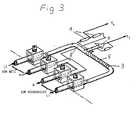
- the shunt 3 and the measuring resistor 5 in the current pathare made of the same material, for example copper, and are thermally there by closely coupled that the measuring resistor 5 is wound around the shunt 3, as can best be seen from FIG. 2.
- the shunt 3is preferably surrounded by a shrink tube which fixes the bifilar wound measuring resistor 5 on the shunt 3. This arrangement has the advantage that the measuring resistor 5 changes in percentage in the same way as the shunt 3 when the temperature changes, so that the current measuring circuit 4 supplies a temperature-compensated voltage signal V without the need for complex constructions or expensive temperature-stable shunt materials.
- the connecting web 8 between the phase input and output of the terminal block of the meteris preferably used as the shunt 3.
- the counter according to the inventionis insensitive to direct current components in the voltage and current path, in contrast to the known Ferrari counters and counters with current transformers.
- the iron-compensated, temperature-compensated current measurement method with a shuntwhich therefore works without saturation, also allows measurement of high currents, e.g. up to 90 A in a single-phase counter, and this simply and inexpensively, without phase errors occurring.
- the output of the two S / H circuits 2 and 7can be connected via a switch 9 alternately to a programmable amplifier 10 and a downstream analog-to-digital converter (A / D converter) 11, the reference voltage of which is supplied by a reference voltage source 12.
- a / D converteranalog-to-digital converter
- the A / D converter 11is connected to a microprocessor 13, which contains various functional circuits and is connected to a display 14. With 15 is a time reference and 16 denotes a power failure-proof EAROM, ie an electrically programmable, erasable and reprogrammable read-only memory. In addition, the microprocessor is still connected to the S / H circuits 2 and 7 and to the programmed amplifier 10.
- the circuit shown in the block diagram in Fig. 1operates as follows.
- the voltage signal V determined by means of the voltage divider 1 and proportional to the consumer voltage and the voltage signal V i determined by means of the current measuring circuit 4are temporarily stored in the S / H circuits 2 and 7.
- the switch 9By means of the switch 9, the values present at the output of the S / H circuits 2 and 7 are sampled with a predetermined sampling frequency.
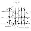
- the scanning principleresults from FIG. 3, which shows the course of the curve and the samples of voltage, current and power.
- the sampling frequencyis then selected such that at least two samples per period in the power range, ie at least four samples per network period in the voltage and current range, are processed.
- the sampling frequencyis also selected so that it always remains asynchronous to the network in the event of possible deviations in the network frequency, so that periodic signals in the basic frequency of the network can be precisely sampled with any waveforms in all phase positions, which is particularly important for measuring the current.
- the sampled values supplied by the S / H circuits 2 and 7are successively digitized by the A / D converter 11 via the programmable amplifier 9 and are stored independently in the microprocessor 13 chert. This makes it possible, depending on the choice of software, for the microprocessor 13 to evaluate and display the active and / or reactive power.
- the digital voltage values V ud and V id stored in the microprocessor 13are multiplied in a multiplication circuit in the microprocessor 13 and then integrated in an integration circuit, so that the consumed instantaneous power is obtained and this can be displayed, for example, in the display 14.
- the meteris calibrated by first performing a calibration measurement with a precision counter, determining the calibration factor once for each device and storing the calibration factor in the EAROM 16, with which the measured values of the meter are then multiplied in the microprocessor. This eliminates all analog trimming operations in the measuring circuit, as they are required in the known meters, which is of great importance for reliability and efficient production.
- the meterSince the meter is calibrated by a correction operation in the microprocessor, the requirements for the analog circuit parts (linearity of the A / D converter and the programmable amplifier, the voltage and time reference) are high only with regard to relative accuracy, long-term and temperature stability, With regard to absolute accuracy, however, tolerances can be accepted which can be achieved with semiconductor circuits as on-chip solutions.
- the possibility of semiconductor integration of the measuring circuitopens the way to rational and future-oriented production of fully electronic meters.
- the analog-digital conversion of the voltage value V iwhich is proportional to the consumption current, is preferably carried out in two steps.
- the programmable amplifier 2is set to the smallest gain (gain factor 1) and the magnitude of the amplitude of the voltage value is roughly determined using the A / D converter.
- one of the amplification factors 1, 2, 4, 8, 16, 32, 64, 128is selected on the basis of the first measurement in the programmable amplifier, in such a way that the subsequent A / D converter is driven as fully as possible.
- This methodhas the advantage that a constant percentage accuracy of the measured values over the entire amplitude range of over 1: 100 of the A / D converter is guaranteed. This makes it possible to accurately display both low and high consumption.
- the analog-to-digital conversion of the voltage value V. proportional to the consumer current in two stepsa constant relative accuracy is achieved over a large measuring range, which meets the requirements placed on an electricity meter changes.
- the value of the energy consumed in each caseis also stored in the EAROM.
- two sample and hold circuitsare provided for each phase and the energy consumed in all three phases is measured.
- theyIn order to bring the phase voltages and currents to the potential of the measuring and evaluation circuit, they must be coupled in a known manner by means of transformers. This is a simple way to obtain a three-phase counter, which also offers the interesting option of displaying the individual phase currents on demand when it comes to distributing the loads equally across the three phases in an installation check or adjust.
Landscapes
- Engineering & Computer Science (AREA)
- Power Engineering (AREA)
- Physics & Mathematics (AREA)
- General Physics & Mathematics (AREA)
- Measurement Of Current Or Voltage (AREA)
- Charge And Discharge Circuits For Batteries Or The Like (AREA)
- Electric Clocks (AREA)
- Developing Agents For Electrophotography (AREA)
Abstract
Description
Translated fromGermanDie Erfindung betrifft einen elektronischen Energieverbrauchszähler und ein Verfahren zur Messung elektrischer Energie mit einem Energieverbrauchszähler.The invention relates to an electronic energy meter and a method for measuring electrical energy with an energy meter.
Zähler für die Verrechnung elektrischer Energie sind in Haushalt und Industrie bisher vorwiegend in elektromechanischer Ausführung mit Ferrarisscheibe als Motor ausgeführt worden. Elektronische Zähler werden demgegenüber bisher nur als Präzisionszähler verwendet, die nach dem Pulsfrequenz- (Mark and Space) arbeiten. Außerdem sind analoge Multiplikationsverfahren bekannt, welche an der Kennlinie der Basis-Emitter-Strecke von Transistoren arbeiten. Hierzu wird verwiesen auf den Multiplizierer mit logarithmierenden Funktionsgeneratoren in Tietze/Schenk, 2. Auflage, Seite 288. Dieses letztgenannte Verfahren hat jedoch den Nachteil, daß es bezüglich Langzeit- und Temperaturstabilität sehr schwer auf die erforderliche Genauigkeit in einem größeren Meßbereich zu bringen ist.Up until now, meters for the calculation of electrical energy in household and industry have mainly been designed in an electromechanical version with a Ferrari disc as a motor. In contrast, electronic counters have so far only been used as precision counters that work according to the pulse frequency (mark and space). In addition, analog multiplication methods are known which work on the characteristic curve of the base-emitter path of transistors. For this, reference is made to the multiplier with logarithmic function generators in Tietze / Schenk, 2nd edition, page 288. However, this latter method has the disadvantage that it is very difficult to achieve the required accuracy in a larger measuring range with regard to long-term and temperature stability.
Die bekannten Verfahren haben darüber hinaus den Nachteil, daß sie schaltungsmäßig sehr aufwendig und damit kostspielig sind.The known methods also have the disadvantage that they are very complex in terms of circuitry and thus are expensive.
Demgegenüber besteht die Aufgabe der Erfindung darin, einen elektronischen Zähler und ein Verfahren zur Messung der verbrauchten elektrischen Energie der oben beschriebenen Art zu schaffen, mit dem die Verbrauchsenergie mit der erforderlichen Genaugigkeit und in einem größeren Meßbereich gemessen und der Schaltungsaufwand trotzdem so gering gehalten werden können, daß der elektronische Zähler sich für die Massenfabrikation eignet und damit auch als Haushaltszähler verwendet werden kann.In contrast, the object of the invention is to provide an electronic meter and a method for measuring the consumed electrical energy of the type described above, with which the consumption energy can be measured with the required accuracy and in a larger measuring range and the circuitry can still be kept so low that the electronic counter is suitable for mass production and can therefore also be used as a household counter.
Diese Aufgabe wird durch einen Zähler der oben beschriebenen Art gelöst, der aufweist: eine Einrichtung zur Erzeugung eines zur Verbraucherspannung proportionalen Spannungssignals, einen ersten Zwischenspeicher, dem das Spannungssignal zugeführt wird, eine Einrichtung zum Erzeugen eines zum Verbraucherstrom proportionalen Spannungssignals, einen zweiten Zwischenspeicher, dem das Spannungssignal zugeführt wird, einen Analog-Digital-Wandler (A/D-wandler) und einen Schalter, der die am Ausgang der Zwischenspeicher anliegenden Abtastwerte mit einer vorbestimmten Abtastfrequenz abwechselnd dem A/D-Wandler zuführt, wobei die Spannungswerte in digitaler Form am Ausgang des A/D-Wandlers nacheinander in einer Form anliegen, in der sie von einem Mikroprozessor einzeln weiterverarbeitbar sind.This object is achieved by a counter of the type described above, which comprises: a device for generating a voltage signal proportional to the consumer voltage, a first buffer to which the voltage signal is fed, a device for generating a voltage signal proportional to the consumer current, a second buffer, the the voltage signal is supplied, an analog-to-digital converter (A / D converter) and a switch which alternately supplies the sample values present at the output of the buffer stores to the A / D converter at a predetermined sampling frequency, the voltage values in digital form on Output of the A / D converter in succession in a form in which they can be individually processed by a microprocessor.
Insbesondere ist dabei der A/D-Wandler mit einem Mikroprozessor verbunden, dem die von dem A/D-Wandler digitalisierten Spannungswerte zugeführt werden und der eine Multiplikationsschaltung zur Multiplikation der digitalen beiden Spannungswerte und eine Integrationsschaltung zur Integration des Ausgangssignals der Multiplikationsschaltung aufweist.In particular, the A / D converter is connected to a microprocessor to which the voltage values digitized by the A / D converter are fed and which has a multiplication circuit for multiplying the digital two voltage values and an integration circuit for integrating the output signal of the multi has circuit.
Damit wird mit geringem Schaltungsaufwand ein Zähler geschaffen, der sich für die Massenfertigung und damit auch als Haushaltszähler eignet.This creates a meter with little circuitry, which is suitable for mass production and therefore also as a household meter.
Weitere vorteilhafte Ausführungsformen der Erfindung sind in den Ansprüchen 2 bis7 beschrieben, die damit als Teil der Beschreibung eingeführt werden; und Vorteile dieser Ausführungsformen sind in der Beschreibung jeweils angegeben.Further advantageous embodiments of the invention are described in
Das erfindungsgemäße Verfahren zur Messung elektrischer Energie mit einem Energieverbrauchszähler ist dadurch gekennzeichnet, daß ein zur Verbraucherspannung proportionaler Spannungswert und ein zum Verbraucherstrom proportionaler Spannungswert ermittelt und gleichzeitig in jeweils einem Speicher zwischengespeichert werden, daß die zwischengespeicherten Spannungswerte über einen mit einer bestimmten Abtastfrequenz betätigten Schalter hintereinander von einem A/D-Wandler digitalisiert und unabhängig voneinander in einem Mikroprozessor gespeichert werden und daß die im Mikroprozessor gespeicherten digitalen Spannungswerte im Mikroprozessor in einer Multiplikationsschaltung multipliziert und dann in einer Integrationsschaltung integriert werden.The method according to the invention for measuring electrical energy with an energy consumption meter is characterized in that a voltage value proportional to the consumer voltage and a voltage value proportional to the consumer current are determined and at the same time temporarily stored in a memory in each case, that the temporarily stored voltage values are successively operated by a switch operated with a certain sampling frequency digitized in an A / D converter and stored independently of one another in a microprocessor and that the digital voltage values stored in the microprocessor are multiplied in a multiplication circuit in the microprocessor and then integrated in an integration circuit.
Weitere vorteilhafte Ausgestaltungen des erfindungsgemäßen Verfahrens sind in den Ansprüchen 8 bis 14 beschrieben, die damit als Teil der Beschreibung eingeführt werden und deren Vorteile in der Beschreibung angegeben sind.Further advantageous refinements of the method according to the invention are described in claims 8 to 14, which are thus introduced as part of the description and whose advantages are specified in the description.
Ausführungsbeispiele der Erfindung werden anhand der Zeichnungen näher beschrieben. Es zeigen:
- Fig. 1 ein Blockschaltbild eines erfindungsgemäßen Zählers und zur Erläuterung des erfindungsgemäßen Verfahrens;
- Fig. 2 eine vergrößerte perspektivische Darstellung der Anschlußklemmen sowie der Eingangsschaltung des erfindungsgemäßen Zählers und
- Fig. 3 Ein Kurvenschaubild zur Verdeutlichung des Abtastprinzips anhand der Abtastwerte von Strom, Spannung und momentaner Leistung.
- 1 shows a block diagram of a counter according to the invention and to explain the method according to the invention;
- Fig. 2 is an enlarged perspective view of the terminals and the input circuit of the counter according to the invention and
- Fig. 3 is a graph to illustrate the sampling principle based on the samples of current, voltage and instantaneous power.
Bei dem in Fig. 1 dargestellten Blockschaltbild ist ein Einphasenzähler auf der Phase Ll eines Drehstromnetzes mit Nulleiter N angeschlossen dargestellt. Zwischen Nulleiter N und Phase L1 ist ein Spannungsteiler 1 geschaltet, an dem ein zur Verbraucherspannung proportionale Spannungssignal V abgenommen und einer ersten Abtast- und Halteschaltung (Sample-and-Hold-Schaltung; S/H-Schaltung) 2 zugeführt wird.In the block diagram shown in FIG. 1, a single-phase counter is shown connected to phase L1 of a three-phase network with neutral conductor N.
Zwischen Phaseneingang und -ausgang ist ein Nebenwiderstand oder Shunt 3 geschaltet, der damit parallel zu einem Strommeßkreis 4 liegt, in dem ein zum Verbraucherstrom proportionales Spannungssignal Viermittelt wird. Der Strommeßkreis 4 weist einen Meßwiderstand 5 sowie einen Operationsverstärker 6 auf, dessen erster Eingang mit dem Phaseneingang und dessen zweiter Eingang mit dem Meßwiderstand 5 verbunden ist. Das am Ausgang des Operationsverstärkers 6 anliegende, zum Verbraucherstrom proportionale Spannungssignal Vi wird einer zweiten Abtast- und Halteschaltung (S/H- Schaltung) 7 zugeführt.A
Der Shunt 3 und der Meßwiderstand 5 im Strompfad sind aus gleichem Material, z.B. Kupfer, und thermisch dadurch eng miteinander gekoppelt, daß der Meßwiderstand 5 um den Shunt 3 herumgewickelt ist, wie es am besten aus Fig. 2 zu ersehen ist. Vorzugsweise ist dabei der Shunt 3 von einem Schrumpfschlauch umgeben, der den bifilar aufgewickelten Meßwiderstand 5 auf dem Shunt 3 fixiert. Diese Anordnung hat den Vorteil, daß sich der Meßwiderstand 5 bei Temperaturänderungen prozentual gleich verändert wie der Shunt 3, so daß der Strommeßkreis 4 ein temperaturkompensiertes Spannungssignal V liefert, ohne daß aufwendige Konstruktionen oder teuere temperaturstabile Shuntmaterialien eingesetzt werden müssen. Vorzugsweise dient dabei als Shunt 3 der Verbindungssteg 8 zwischen Phaseneingang und -ausgang des Klemmblocks des Zählers.The
Dadurch daß sowohl der Spannungs- als auch der Strommeßkreis eisenlos sind, ist der erfindungsgemäße Zähler gegenüber Gleichstromanteilen im Spannungs- und Strompfad unempfindlich, im Gegensatz zu den bekannten Ferrarizählern und Zählern mit Stromwandlern. Außerdem gestattet das eisenlos und daher ohne Sättigungserscheinungen arbeitende, temperaturkompensierte Strommeßverfahren mit einem Shunt auch eine Messung hoher Ströme, z.B. bis 90 A in einem Einphasenzähler, und dies einfach und kostengünstig, ohne daß Phasenfehler auftreten.Because both the voltage and the current measuring circuit are ironless, the counter according to the invention is insensitive to direct current components in the voltage and current path, in contrast to the known Ferrari counters and counters with current transformers. In addition, the iron-compensated, temperature-compensated current measurement method with a shunt, which therefore works without saturation, also allows measurement of high currents, e.g. up to 90 A in a single-phase counter, and this simply and inexpensively, without phase errors occurring.
Der Ausgang der beiden S/H-Schaltungen 2 und 7 ist über einen Schalter 9 abwechselnd mit einem programmierbaren Verstärker 10 und einem nachgeschalteten Analog-Digital-Wandler (A/D-Wandler) 11 verbindbar, dessen Bezugsspannung von einer Bezugsspannungsquelle 12 geliefert wird.The output of the two S /
Der A/D-Wandler 11 ist mit einem Mikroprozessor 13 verbunden, der verschiedene Funktionsschaltungen beinhaltet und mit einer Anzeige 14 verbunden ist. Mit dem Bezugszeichen 15 ist eine Zeitreferenz und mit 16 ein netzausfallsicherer EAROM gekennzeichnet, d.h. ein elektrisch programmier-, lösch- und wiederprogrammierbarer Festwertspeicher. Außerdem ist der Mikroprozessor noch mit den S/H-Schaltungen 2 und 7 sowie mit dem programmierten Verstärker 10 verbunden.The A /
Die im Blockschaltbild in Fig. 1 dargestellte Schaltung arbeitet wie folgt.The circuit shown in the block diagram in Fig. 1 operates as follows.
Das mittels Spannungsteiler 1 ermittelte, zur Verbraucherspannung proportionale Spannungssignal V und das mittels Strommeßkreis 4 ermittelte, zum Verbraucherstrom proportionale Spannungssignal Vi werden in den S/H-Schaltungen 2 und 7 zwischengespeichert. Mittels des Schalters 9 werden die an dem Ausgang der S/H-Schaltungen 2 und 7 anliegenden Werte mit einer vorbestimmten Abtastfrequenz abgetastet. Das Abtastprinzip ergibt sich aus Fig. 3, die den Kurvenverlauf und die Abtastwerte von Spannung, Strom und Leistung zeigt. Danach wird die Abtastfrequenz so gewählt, daß mindestens zwei Abtastwerte pro Periode im Leistungsbereich, d.h. wenigstens vier Abtastwerte pro Netzperiode im Spannungs- und Strombereich verarbeitet werden. Die Abtastfrequenz wird ferner so gewählt, daß sie bei den möglichen Abweichungen der Netzfrequenz immer asynchron zum Netz bleibt, damit periodische Signale in der Grundfrequenz des Netzes mit beliebigen Kurvenformen in allen Phasenlagen genau abgetastet werden, was insbesondere für die Messung des Stromes wichtig ist.The voltage signal V determined by means of the
Die von den S/H-Schaltungen 2 und 7 gelieferten Abtastwerte werden über den programmierbaren Verstärker 9 von dem A/D-wandler 11 nacheinander digitalisiert und unabhängig voneinander im Mikroprozessor 13 abgespeichert. Dadurch ist es möglich, daß je nach Wahl der Software vom Mikroprozessor 13 die Wirk- und/oder Blindleistung ausgewertet und angezeigt werden kann.The sampled values supplied by the S /
Die im Mikroprozessor 13 gespeicherten digitalen Spannungswerte Vud und Vid werden im Mikroprozessor 13 in einer Multiplikationsschaltung multipliziert und dann in einer Integrationsschaltung integriert, so daß damit die verbrauchte momentane Leistung erhalten wird und diese beispielsweise in der Anzeige 14 angezeigt werden kann.The digital voltage values Vud and Vid stored in the
Dadurch daß die Spannungswerte Vud und Vid unabhängig voneinander im Mikroprozessor 13 gespeichert werden, ist es auch möglich, etwaige Strom- oder Spannungsoffsetfehler dadurch im Mikroprozessor 13 zu beseitigen, daß laufend über Sekunden bis Minuten der Mittelwert der digitalen Spannungsabtastwerte Vud und Vid gebildet und sich daraus ergebende Nullpunktsverschiebungen jedem Abtastwert im korrigierenden Sinne hinzuaddiert oder subtrahiert werden, bevor die Abtastwerte der Multiplikationsschaltung im Mikroprozessor 13 zugeführt werden.Characterized in that the voltage values Vud Vid independently in the
Eine Eichung des Zählers wird dadurch vorgenommen, daß vorab eine Eichmessung mit einem Präzisionszähler durchgeführt, der Eichfaktor einmalig für jedes Gerät individuell ermittelt und in dem EAROM 16 der Eichfaktor abgespeichert wird, mit dem die Meßwerte des Zählers dann im Mikroprozessor multipliziert werden. Dadurch entfallen sämtliche analogen Trimmoperationen in der Meßschaltung, wie sie bei den bekannten Zählern erforderlich sind, was für die Zuverlässigkeit und rationelle Fertigung von hoher Wichtigkeit ist.The meter is calibrated by first performing a calibration measurement with a precision counter, determining the calibration factor once for each device and storing the calibration factor in the EAROM 16, with which the measured values of the meter are then multiplied in the microprocessor. This eliminates all analog trimming operations in the measuring circuit, as they are required in the known meters, which is of great importance for reliability and efficient production.
Da die Eichung des Zählers durch eine Korrekturoperation im Mikroprozessor erfolgt, sind die Anforderungen an die analogen Schaltungsteile (Linearität des A/D-Wandlers und des programmierbaren Verstärkers, der Spannungs- und Zeitreferenz) nur noch bezüglich relativer Genauigkeit, Langzeit- und Temperaturstabilität hoch, bezüglich absoluter Genauigkeit können jedoch Toleranzen akzeptiert werden, welche mit Halbleiterschaltungen als On-Chip-Lösungen erreicht werden können. Die Möglichkeit der Halbleiterintegration des Meßkreises eröffnet damit den Weg zur rationellen und zukunftsgerichteten Fertigung voll elektronischer Zähler.Since the meter is calibrated by a correction operation in the microprocessor, the requirements for the analog circuit parts (linearity of the A / D converter and the programmable amplifier, the voltage and time reference) are high only with regard to relative accuracy, long-term and temperature stability, With regard to absolute accuracy, however, tolerances can be accepted which can be achieved with semiconductor circuits as on-chip solutions. The possibility of semiconductor integration of the measuring circuit opens the way to rational and future-oriented production of fully electronic meters.
Vorzugsweise erfolgt die Analog-Digital-Wandlung des zum Verbrauchstrom proportionalen Spannungswerts Vi in zwei Schritten. Im ersten Schritt wird der programmierbarer Verstärker 2 auf die kleinste Verstärkung (Verstärkungsfaktor 1) eingestellt und mit dem A/D-Wandler wird die Größenordnung der Amplitude des Spannungswerts grob festgestellt. Im zweiten Schritt wird aufgrund der ersten Messung im programmierbaren Verstärker einer der Verstärkungsfaktoren 1, 2, 4, 8, 16, 32, 64, 128 angewählt und zwar so, daß der nachfolgende A/D-Wandler möglichst voll ausgesteuert wird. Dieses Verfahren hat den Vorteil, daß eine gleichbleibende prozentuale Genauigkeit der Meßwerte über den gesamten Amplitudenbereich von über 1 : 100 des A/D-Wandlers gewährleistet ist. Damit ist es möglich, sowohl einen geringen als auch einen großen Verbrauch genau anzuzeigen. Mit der Analog-Digital-Wandlung des zum Verbraucherstrom proportionalen Spannungswerts V. in zwei Schritten wird damit eine gleichbleibende relative Genauigkeit über einen großen Meßbereich erreicht, was den an einen Elektrizitätszähler gestellten Anforderungen entspricht.The analog-digital conversion of the voltage value Vi, which is proportional to the consumption current, is preferably carried out in two steps. In the first step, the
Bei einer bevorzugten Ausgestaltung des erfindungsgemäßen Verfahrens wird der Wert der jeweils ermittelten verbrauchten Energie ebenfalls im EAROM gespeichert. Dies erlaubt es, die Ablesung des Zählerstands und evtl. weiterer Angaben wie Überschreitung der tariflich vereinbarten maximal zulässigen momentanen Leistung usw. nicht nur über die Anzeige vor Ort vorzunehmen, sondern auch über zwei Drahtleitungen, Telefonmodems oder Zweiweg-Rundsteuersysteme an einen entfernten Ort oder an das Elektrizätswerk direkt zurückzumelden. Dadurch können viele Probleme im Zusammenhang mit der Zählerablesung wesentlich verbessert werden. Eine Abwesenheit der Bewohner bei der Ablesung stört nicht mehr. Eine genaue und fehlerfreie, da automatische Zählerablesung ist ebenso möglich wie eine Signalisierung von unerlaubten Manipulationen am Zählgerät.In a preferred embodiment of the method according to the invention, the value of the energy consumed in each case is also stored in the EAROM. This makes it possible to read the meter reading and possibly other information such as exceeding the agreed maximum permissible instantaneous power etc. not only via the on-site display, but also via two wire lines, telephone modems or two-way ripple control systems to a remote location or to to report the power plant directly. This can significantly improve many meter reading problems. An absence of residents during the reading no longer disturbs. Accurate and error-free, as automatic meter reading is possible as well as signaling of unauthorized manipulations on the counter.
Durch die unabhängige Messung von Strom und Spannung sowie der unabhängigen Speicherung der dazu proportionalen Spannungswerte kann auch die Überschreitung von Spitzenwerten in Strom, Blind- oder Wirkleistung nach Bedarf signalisiert oder tariflich entsprechend gezählt werden.The independent measurement of current and voltage as well as the independent storage of the voltage values proportional to this means that exceeding peak values in current, reactive or active power can be signaled as required or counted accordingly in accordance with tariffs.
Bei einer weiteren Ausgestaltung des erfindungsgemäßen Verfahrens sind pro Phase jeweils zwei Abtast- und Halteschaltungen vorgesehen und es wird die in allen drei Phasen verbrauchte Energie gemessen. Um die Phasenspannungen und -ströme auf das Potential der Meß- und Auswerteschaltung zu bringen, müssen diese in bekannter Weise transformatorisch gekoppelt werden. Damit erhält man auf einfache Weise einen Drei-Phasenzähler, bei dem sich zusätzlich die interessante Möglichkeit bietet, die einzelnen Phasenströme auf Abruf hin anzuzeigen, wenn es darum geht, in einer Installation die Gleichverteilung der Lasten auf die drei Phasen zu überprüfen oder anzupassen.In a further embodiment of the method according to the invention, two sample and hold circuits are provided for each phase and the energy consumed in all three phases is measured. In order to bring the phase voltages and currents to the potential of the measuring and evaluation circuit, they must be coupled in a known manner by means of transformers. This is a simple way to obtain a three-phase counter, which also offers the interesting option of displaying the individual phase currents on demand when it comes to distributing the loads equally across the three phases in an installation check or adjust.
Wie bereits aus der obigen Beschreibung ersichtlich ist, sind durch die Tatsache, daß die zum Verbraucherstrom bzw. zur Verbraucherspannung proportionalen Spannungswerte in digitaler Form am Ausgang des AD-Wandlers nacheinander in einer Form anliegen, in der sie von einem Mikroprozessor einzeln weiterverarbeitbar sind, vielfältige Auswertungsmöglichkeiten durch den Mikroprozessor geschaffen worden.As can already be seen from the above description, the fact that the voltage values proportional to the consumer current or to the consumer voltage are present in digital form at the output of the AD converter in succession in a form in which they can be individually further processed by a microprocessor Evaluation options have been created by the microprocessor.
Nachfolgend wird die Auswertung der Abtastwerte von Strom und Spannung am Beispiel eines Zwei-Tarifzählers für Wirkleistung dargestellt:
Claims (14)
Translated fromGermangekennzeichnet durch
marked by
dadurch gekennzeichnet,
daß mit dem Ausgang des A/D-Wandlers (11) ein Mikroprozessor (13) verbunden ist, dem die von dem A/D-Wandler (11) digitalisierten Spannungswerte (Vud,Vid) zugeführt werden und der eine Multiplikationsschaltung zur Multiplikation der digitalen beiden Spannungswerte (Vud, Vid) und eine Integrationsschaltung zur Integration des Ausgangssignals der Multiplikationsschaltung aufweist und/oder die Einrichtung zur Erzeugung eines zur Verbraucherspannung proportionalen Spannungssignals (V ) ein Spannungsteiler (1) ist und/oder die Einrichtung zur Erzeugung eines zum Verbraucherstrom proportionalen Spannungssignals (Vi) einen zum StrommeBkreis (4) parallel geschalteten Nebenwiderstand oder Shunt (3) zwischen Phaseneingang und -ausgang, wobei der Phaseneingang mit dem ersten Eingang eines Operationsverstärkers (6) verbunden ist, und einen Meßwiderstand (5) aufweist, der zwischen dem Phasenausgang und dem zweiten Eingang des Operationsverstärkers (6) geschaltet ist.2. Counter according to claim 1,
characterized,
that a microprocessor (13) is connected to the output of the A / D converter (11), to which the voltage values (Vud ,Vid ) digitized by the A / D converter (11) are fed and which has a multiplication circuit for multiplying the digital two voltage values (Vud , Vid ) and an integration circuit for integrating the output signal of the multiplication circuit and / or the device for generating a voltage signal (V) proportional to the consumer voltage is a voltage divider (1) and / or the device for Generation of a voltage signal (Vi ) proportional to the consumer current, a shunt (3) connected in parallel with the current measuring circuit (4) between the phase input and output, the phase input being connected to the first input of an operational amplifier (6), and a measuring resistor (5 ), which is connected between the phase output and the second input of the operational amplifier (6).
dadurch gekennzeichnet,
characterized,
dadurch gekennzeichnet,
daß der Meßwiderstand (5) um den Nebenwiderstand (3) herumgewickelt sowie bifilar als isolierter Draht auf dem Nebenwiderstand (3) aufgewickelt und durch einen umfassenden Schrumpfschlauch darauf fixiert ist.4. Counter according to one of claims 2 or 3,
characterized,
that the measuring resistor (5) is wound around the shunt (3) and bifilarly wound as an insulated wire on the shunt (3) and fixed thereon by a comprehensive shrink tube.
dadurch gekennzeichnet,
daß der Nebenwiderstand (3) vom Verbindungssteg zwischen dem Phaseneingang und -ausgang im Klemmblock des Zählers gebildet wird.5. Counter according to one of claims 2 to 4,
characterized,
that the shunt (3) is formed by the connecting bridge between the phase input and output in the terminal block of the counter.
dadurch gekennzeichnet,
daß die Zwischenspeicher von Abtast- und Halteschaltungen (S/H-Schaltungen) (2, 7) gebildet werden und die Spannungssignale (V , Vi) gleichzeitig in den jeweiligen S/H-Schaltungen (2, 7) gespeichert und anschließend durch Betätigung des Schalters (9) nacheinander durch den A/D-Wandler (11) digitalisiert werden.6. Counter according to one of claims 1 to 5,
characterized,
that the latches of sample and hold circuits (S / H circuits) (2, 7) are formed and the voltage signals (V, Vi ) are simultaneously stored in the respective S / H circuits (2, 7) and then by actuation of the switch (9) are digitized one after the other by the A / D converter (11).
dadurch gekennzeichnet,
characterized,
dadurch gekennzeichnet,
characterized,
dadurch gekennzeichnet,
characterized,
dadurch gekennzeichnet,
daß die A/D-Wandlung des zum Verbraucherstrom proportionalen Spannungswerts (Vi) in zwei Schritten vollzogen wird, wobei im ersten Schritt ein zwischen dem Schalter und dem A/D-Wandler geschalteter programmierbarer Verstärker auf den kleinsten Verstärkungsfaktor eingestellt und mit dem A/D-Wandler damit die Größenordnung des Spannungswerts (Vi) grob eingestellt wird und wobei im zweiten Schritt der Verstärkungsfaktor des programmierbaren Verstärkers so eingestellt wird, daß der nachfolgende A/D-Wandler voll ausgesteuert wird.10. The method according to any one of claims 8 or 9,
characterized,
that the A / D conversion of the voltage value (Vi ) proportional to the consumer current is carried out in two steps, in the first step a programmable amplifier connected between the switch and the A / D converter being set to the smallest amplification factor and with the A / D converter thus the order of magnitude of the voltage value (Vi ) is roughly set and in the second step the gain factor of the programmable amplifier is set so that the subsequent A / D converter is fully controlled.
dadurch gekennzeichnet,
daß die Offsetspannungen der Spannungswerte (Vu, Vi) dadurch kompensiert werden, daß der Mikroprozessor
eine Schaltung zur Mittelwertbildung der digitalisierten Spannungswerte (Vud, Vid) aufweist und die im Mikroprozessor gespeicherten digitalen Spannungswerte entsprechend dem Ergebnis der Mittelwertbildung korrigiert werden.11. The method according to any one of claims 8 to 10,
characterized,
that the offset voltages of the voltage values (Vu , Vi ) are compensated in that the microprocessor
has a circuit for averaging the digitized voltage values (Vud , Vid ) and the digital voltage values stored in the microprocessor are corrected in accordance with the result of the averaging.
dadurch gekennzeichnet,
daß die Eichung des Zählers dadurch erfolgt, daß vorab eine Eichmessung mit einem Präzisionszähler durchgeführt, der Eichfaktor ermittelt und in einem EAROM (Festwertspeicher) der Eichfaktor abgespeichert wird, mit dem die Meßwerte des Zählers dann im Mikroprozessor multipliziert werden und
daß der Wert der jeweils ermittelten verbrauchten Energie ebenfalls im EAROM gespeichert wird.12. The method according to any one of claims 8 to 11,
characterized,
that the meter is calibrated by first performing a calibration measurement with a precision counter, determining the calibration factor and storing the calibration factor in an EAROM (read-only memory), with which the measured values of the counter are then multiplied in the microprocessor and
that the value of the energy determined in each case is also stored in the EAROM.
dadurch gekennzeichnet,
daß die Energie auf einer, zwei oder drei Phasen gemessen wird und
daß pro Phase jeweils zwei Abtast- und Halteschaltungen vorgesehen und die in jeder Phase gemessene Energie im Mikroprozessor zusammengezählt wird.13. The method according to any one of claims 8 to 12,
characterized,
that the energy is measured in one, two or three phases and
that two sample and hold circuits are provided for each phase and the energy measured in each phase is added together in the microprocessor.
dadurch gekennzeichnet,
daß der Energieverbrauchszähler neben der Wirkleistung durch Auswertung der Strom- und Spannungs-Abtastwerte auch die Scheinleistung und/oder aus Wirk- und Scheinleistung auch die Blindleisstung der Netzlast berechnen, anzeigen und integrieren kann.14. The method according to any one of claims 8 to 13,
characterized,
that the energy consumption meter can calculate, display and integrate not only the active power by evaluating the current and voltage samples, but also the apparent power and / or the active power and apparent power also the reactive power consumption of the network load.
Priority Applications (1)
| Application Number | Priority Date | Filing Date | Title |
|---|---|---|---|
| AT85103846TATE48705T1 (en) | 1984-04-17 | 1985-03-29 | ELECTRONIC ENERGY CONSUMPTION METER. |
Applications Claiming Priority (2)
| Application Number | Priority Date | Filing Date | Title |
|---|---|---|---|
| DE3414520 | 1984-04-17 | ||
| DE19843414520DE3414520A1 (en) | 1984-04-17 | 1984-04-17 | ELECTRONIC ENERGY CONSUMER AND METHOD FOR MEASURING ELECTRICAL ENERGY WITH AN ENERGY CONSUMER |
Publications (2)
| Publication Number | Publication Date |
|---|---|
| EP0161447A1true EP0161447A1 (en) | 1985-11-21 |
| EP0161447B1 EP0161447B1 (en) | 1989-12-13 |
Family
ID=6233836
Family Applications (1)
| Application Number | Title | Priority Date | Filing Date |
|---|---|---|---|
| EP85103846AExpiredEP0161447B1 (en) | 1984-04-17 | 1985-03-29 | Electronic energy consumption meter |
Country Status (4)
| Country | Link |
|---|---|
| EP (1) | EP0161447B1 (en) |
| AT (1) | ATE48705T1 (en) |
| DE (2) | DE3414520A1 (en) |
| FR (1) | FR2563013B1 (en) |
Cited By (11)
| Publication number | Priority date | Publication date | Assignee | Title |
|---|---|---|---|---|
| EP0278223A1 (en)* | 1987-01-21 | 1988-08-17 | Siemens Aktiengesellschaft | Static power measuring apparatus |
| FR2616227A1 (en)* | 1987-06-02 | 1988-12-09 | Nibart Olivier | Device for metering the consumption of electrical energy |
| EP0232173A3 (en)* | 1986-02-06 | 1989-08-02 | Oliver J. Nilsen (Australia) Limited | Electrical energy-consumption analyser |
| AU612574B2 (en)* | 1982-09-24 | 1991-07-18 | Sangamo Weston, Inc. | Gain switching device with reduced error for watt meter |
| EP0420545A3 (en)* | 1989-09-25 | 1992-07-08 | General Electric Company | Electronic watthour meter |
| US5245275A (en)* | 1989-09-25 | 1993-09-14 | General Electric Company | Electronic watthour meter |
| US5258704A (en)* | 1989-09-25 | 1993-11-02 | General Electric Company | Electronic watthour meter |
| US5289115A (en)* | 1989-09-25 | 1994-02-22 | General Electric Company | Electronic watt-hour meter with selection of time base signals |
| WO1999009421A1 (en)* | 1997-08-20 | 1999-02-25 | Cambridge Consultants Limited | Current monitoring device |
| WO2013093554A1 (en) | 2011-12-21 | 2013-06-27 | Rīgas Tehniskā Universitāte | System and method for monitoring real power consumption |
| US9760956B2 (en) | 2011-04-08 | 2017-09-12 | Sma Solar Technology Ag | Optimized load management |
Families Citing this family (3)
| Publication number | Priority date | Publication date | Assignee | Title |
|---|---|---|---|---|
| DE3707707A1 (en)* | 1987-03-11 | 1988-09-29 | Pfisterer Elektrotech Karl | Measuring transducer |
| DE4403642C1 (en)* | 1994-02-05 | 1994-12-08 | Licentia Gmbh | Method for measuring active power and measuring device therefor |
| DE19639410A1 (en) | 1996-09-25 | 1998-04-02 | Siemens Ag | Measuring device for electrical power |
Citations (4)
| Publication number | Priority date | Publication date | Assignee | Title |
|---|---|---|---|---|
| FR2357907A1 (en)* | 1976-07-07 | 1978-02-03 | Heliowatt Werke | KILOWATHEUREMETER WITH STATIC MEASURING ELEMENT |
| EP0008630A1 (en)* | 1978-07-17 | 1980-03-19 | Siemens Aktiengesellschaft | Power/frequency converter with a microcomputer |
| GB2082785A (en)* | 1980-08-28 | 1982-03-10 | Valeron Corp | Power measuring device |
| EP0057978A1 (en)* | 1981-01-14 | 1982-08-18 | Westinghouse Electric Corporation | High accuracy AC electric energy metering system |
- 1984
- 1984-04-17DEDE19843414520patent/DE3414520A1/ennot_activeWithdrawn
- 1984-06-06FRFR8408857Apatent/FR2563013B1/ennot_activeExpired
- 1985
- 1985-03-29ATAT85103846Tpatent/ATE48705T1/ennot_activeIP Right Cessation
- 1985-03-29DEDE8585103846Tpatent/DE3574778D1/ennot_activeExpired - Lifetime
- 1985-03-29EPEP85103846Apatent/EP0161447B1/ennot_activeExpired
Patent Citations (4)
| Publication number | Priority date | Publication date | Assignee | Title |
|---|---|---|---|---|
| FR2357907A1 (en)* | 1976-07-07 | 1978-02-03 | Heliowatt Werke | KILOWATHEUREMETER WITH STATIC MEASURING ELEMENT |
| EP0008630A1 (en)* | 1978-07-17 | 1980-03-19 | Siemens Aktiengesellschaft | Power/frequency converter with a microcomputer |
| GB2082785A (en)* | 1980-08-28 | 1982-03-10 | Valeron Corp | Power measuring device |
| EP0057978A1 (en)* | 1981-01-14 | 1982-08-18 | Westinghouse Electric Corporation | High accuracy AC electric energy metering system |
Non-Patent Citations (2)
| Title |
|---|
| IEEE TRANS. ON INDUSTRIAL ELECTR. & CONTROL INSTR., Band IECI-28, Nr. 3, August 1981, Seiten 180-184, IEEE, New York, US; J.J. HILL et al.: "Design of a microprocessor-based digital Wattmeter"* |
| WESCON CONFERENCE RECORD, Band 25, September 1981, Seiten 1-7(7/2), El Segundo, CA, US; R. TALAMBIRAS: "Sampling network analyzer for periodic functions"* |
Cited By (12)
| Publication number | Priority date | Publication date | Assignee | Title |
|---|---|---|---|---|
| AU612574B2 (en)* | 1982-09-24 | 1991-07-18 | Sangamo Weston, Inc. | Gain switching device with reduced error for watt meter |
| EP0232173A3 (en)* | 1986-02-06 | 1989-08-02 | Oliver J. Nilsen (Australia) Limited | Electrical energy-consumption analyser |
| EP0278223A1 (en)* | 1987-01-21 | 1988-08-17 | Siemens Aktiengesellschaft | Static power measuring apparatus |
| FR2616227A1 (en)* | 1987-06-02 | 1988-12-09 | Nibart Olivier | Device for metering the consumption of electrical energy |
| EP0420545A3 (en)* | 1989-09-25 | 1992-07-08 | General Electric Company | Electronic watthour meter |
| US5245275A (en)* | 1989-09-25 | 1993-09-14 | General Electric Company | Electronic watthour meter |
| US5258704A (en)* | 1989-09-25 | 1993-11-02 | General Electric Company | Electronic watthour meter |
| US5289115A (en)* | 1989-09-25 | 1994-02-22 | General Electric Company | Electronic watt-hour meter with selection of time base signals |
| EP0645636A1 (en)* | 1989-09-25 | 1995-03-29 | General Electric Company | Electronic watthour meter |
| WO1999009421A1 (en)* | 1997-08-20 | 1999-02-25 | Cambridge Consultants Limited | Current monitoring device |
| US9760956B2 (en) | 2011-04-08 | 2017-09-12 | Sma Solar Technology Ag | Optimized load management |
| WO2013093554A1 (en) | 2011-12-21 | 2013-06-27 | Rīgas Tehniskā Universitāte | System and method for monitoring real power consumption |
Also Published As
| Publication number | Publication date |
|---|---|
| FR2563013B1 (en) | 1988-01-22 |
| EP0161447B1 (en) | 1989-12-13 |
| DE3574778D1 (en) | 1990-01-18 |
| FR2563013A1 (en) | 1985-10-18 |
| DE3414520A1 (en) | 1985-10-24 |
| ATE48705T1 (en) | 1989-12-15 |
Similar Documents
| Publication | Publication Date | Title |
|---|---|---|
| DE69126739T2 (en) | Digital measurement of electrical energy consumption | |
| EP0161447B1 (en) | Electronic energy consumption meter | |
| DE2821225C2 (en) | ||
| DE2917237C2 (en) | ||
| DE3126485C2 (en) | ||
| EP0221251B1 (en) | Fault-compensating method for sensing elements with non-linear characteristics, and device for performing it | |
| DE3335868C2 (en) | ||
| DE3122168A1 (en) | Electronic active-energy meter | |
| DE69026162T2 (en) | Measuring system for electrical power | |
| EP0043536A2 (en) | Control system to adjust a physical value | |
| DE2519668C3 (en) | Arrangement for generating a sequence of pulses proportional to the product of two analog electrical quantities | |
| DE2530374A1 (en) | ELECTRONIC MEASURING CONVERTER FOR MONITORING TWO AC SIGNALS | |
| DE68907023T2 (en) | MICROCOMPUTER CONTROLLED CIRCUIT FOR LOCALIZATION OF INSULATION FAULTS. | |
| CH653445A5 (en) | METHOD AND DEVICE FOR MEASURING AN ELECTRICAL RESISTANCE. | |
| DE1673249A1 (en) | Adjustment device for magnetic fields with an inductive voltage divider and spectrometer equipped with it | |
| DE2042687C3 (en) | Power frequency converter arrangement, in particular for testing electricity meters | |
| CH668840A5 (en) | ELECTRONIC ENERGY METER FOR ELECTRICAL ENERGY. | |
| DE2939521C2 (en) | mass spectrometry | |
| EP0438637A1 (en) | Method and apparatus for the determination of an effective value Ieff of a current to be measured using a Hall element and an amplifier circuit | |
| DE2305204A1 (en) | SYSTEM FOR CONVERTING AN INPUT SIGNAL INTO A LOGARITHMIC VALUE | |
| DE3617936A1 (en) | Arrangement for digital voltage measurement | |
| DE2508033A1 (en) | Measurement of capacitance and loss factor - using automatic range finding network involving relays and comparators | |
| EP1460438A1 (en) | Modular electricity meter | |
| DE2923341A1 (en) | Electronic multiphase electricity meter - has regulated common supply for all individual phase measurement sections using separate secondaries | |
| DE3819370A1 (en) | Device for measuring direct current |
Legal Events
| Date | Code | Title | Description |
|---|---|---|---|
| PUAI | Public reference made under article 153(3) epc to a published international application that has entered the european phase | Free format text:ORIGINAL CODE: 0009012 | |
| AK | Designated contracting states | Designated state(s):AT CH DE FR GB LI SE | |
| 17P | Request for examination filed | Effective date:19860217 | |
| 17Q | First examination report despatched | Effective date:19880715 | |
| GRAA | (expected) grant | Free format text:ORIGINAL CODE: 0009210 | |
| AK | Designated contracting states | Kind code of ref document:B1 Designated state(s):AT CH DE FR GB LI SE | |
| REF | Corresponds to: | Ref document number:48705 Country of ref document:AT Date of ref document:19891215 Kind code of ref document:T | |
| REF | Corresponds to: | Ref document number:3574778 Country of ref document:DE Date of ref document:19900118 | |
| ET | Fr: translation filed | ||
| GBT | Gb: translation of ep patent filed (gb section 77(6)(a)/1977) | ||
| PLBI | Opposition filed | Free format text:ORIGINAL CODE: 0009260 | |
| 26 | Opposition filed | Opponent name:ZELLWEGER USTER AG Effective date:19900913 | |
| PLBN | Opposition rejected | Free format text:ORIGINAL CODE: 0009273 | |
| STAA | Information on the status of an ep patent application or granted ep patent | Free format text:STATUS: OPPOSITION REJECTED | |
| 27O | Opposition rejected | Effective date:19920328 | |
| REG | Reference to a national code | Ref country code:CH Ref legal event code:PUE Owner name:ZELLWEGER USTER AG | |
| EAL | Se: european patent in force in sweden | Ref document number:85103846.3 | |
| REG | Reference to a national code | Ref country code:FR Ref legal event code:TP | |
| REG | Reference to a national code | Ref country code:GB Ref legal event code:732E | |
| PGFP | Annual fee paid to national office [announced via postgrant information from national office to epo] | Ref country code:SE Payment date:19980130 Year of fee payment:14 Ref country code:FR Payment date:19980130 Year of fee payment:14 | |
| PGFP | Annual fee paid to national office [announced via postgrant information from national office to epo] | Ref country code:AT Payment date:19980223 Year of fee payment:14 | |
| PGFP | Annual fee paid to national office [announced via postgrant information from national office to epo] | Ref country code:CH Payment date:19980312 Year of fee payment:14 | |
| PGFP | Annual fee paid to national office [announced via postgrant information from national office to epo] | Ref country code:GB Payment date:19980320 Year of fee payment:14 | |
| PGFP | Annual fee paid to national office [announced via postgrant information from national office to epo] | Ref country code:DE Payment date:19980324 Year of fee payment:14 | |
| REG | Reference to a national code | Ref country code:FR Ref legal event code:TP | |
| REG | Reference to a national code | Ref country code:GB Ref legal event code:732E | |
| PG25 | Lapsed in a contracting state [announced via postgrant information from national office to epo] | Ref country code:GB Free format text:LAPSE BECAUSE OF NON-PAYMENT OF DUE FEES Effective date:19990329 Ref country code:AT Free format text:LAPSE BECAUSE OF NON-PAYMENT OF DUE FEES Effective date:19990329 | |
| PG25 | Lapsed in a contracting state [announced via postgrant information from national office to epo] | Ref country code:SE Free format text:LAPSE BECAUSE OF NON-PAYMENT OF DUE FEES Effective date:19990330 | |
| PG25 | Lapsed in a contracting state [announced via postgrant information from national office to epo] | Ref country code:LI Free format text:LAPSE BECAUSE OF NON-PAYMENT OF DUE FEES Effective date:19990331 Ref country code:CH Free format text:LAPSE BECAUSE OF NON-PAYMENT OF DUE FEES Effective date:19990331 | |
| EUG | Se: european patent has lapsed | Ref document number:85103846.3 | |
| REG | Reference to a national code | Ref country code:CH Ref legal event code:PL | |
| GBPC | Gb: european patent ceased through non-payment of renewal fee | Effective date:19990329 | |
| PG25 | Lapsed in a contracting state [announced via postgrant information from national office to epo] | Ref country code:FR Free format text:LAPSE BECAUSE OF NON-PAYMENT OF DUE FEES Effective date:19991130 | |
| EUG | Se: european patent has lapsed | Ref document number:85103846.3 | |
| REG | Reference to a national code | Ref country code:FR Ref legal event code:ST | |
| PG25 | Lapsed in a contracting state [announced via postgrant information from national office to epo] | Ref country code:DE Free format text:LAPSE BECAUSE OF NON-PAYMENT OF DUE FEES Effective date:20000101 | |
| PLAB | Opposition data, opponent's data or that of the opponent's representative modified | Free format text:ORIGINAL CODE: 0009299OPPO |