EP0159750B1 - Deep-frying device - Google Patents
Deep-frying deviceDownload PDFInfo
- Publication number
- EP0159750B1 EP0159750B1EP19850200513EP85200513AEP0159750B1EP 0159750 B1EP0159750 B1EP 0159750B1EP 19850200513EP19850200513EP 19850200513EP 85200513 AEP85200513 AEP 85200513AEP 0159750 B1EP0159750 B1EP 0159750B1
- Authority
- EP
- European Patent Office
- Prior art keywords
- container
- deep
- frying
- cast
- ribs
- Prior art date
- Legal status (The legal status is an assumption and is not a legal conclusion. Google has not performed a legal analysis and makes no representation as to the accuracy of the status listed.)
- Expired
Links
- 239000007789gasSubstances0.000claimsdescription11
- 239000000567combustion gasSubstances0.000claimsdescription7
- 238000007599dischargingMethods0.000claimsdescription3
- 239000012530fluidSubstances0.000claimsdescription3
- 229910000838Al alloyInorganic materials0.000claimsdescription2
- 238000004381surface treatmentMethods0.000claimsdescription2
- 238000013021overheatingMethods0.000description4
- XAGFODPZIPBFFR-UHFFFAOYSA-NaluminiumChemical compound[Al]XAGFODPZIPBFFR-UHFFFAOYSA-N0.000description2
- 229910052782aluminiumInorganic materials0.000description2
- 239000004411aluminiumSubstances0.000description2
- 230000002349favourable effectEffects0.000description2
- 238000004519manufacturing processMethods0.000description2
- 239000010935stainless steelSubstances0.000description2
- 229910001220stainless steelInorganic materials0.000description2
- 238000005266castingMethods0.000description1
- 238000004140cleaningMethods0.000description1
- 239000011248coating agentSubstances0.000description1
- 238000000576coating methodMethods0.000description1
- 238000005260corrosionMethods0.000description1
- 230000007797corrosionEffects0.000description1
- 238000010438heat treatmentMethods0.000description1
- 238000000034methodMethods0.000description1
- 238000010792warmingMethods0.000description1
Images

Classifications
- A—HUMAN NECESSITIES
- A47—FURNITURE; DOMESTIC ARTICLES OR APPLIANCES; COFFEE MILLS; SPICE MILLS; SUCTION CLEANERS IN GENERAL
- A47J—KITCHEN EQUIPMENT; COFFEE MILLS; SPICE MILLS; APPARATUS FOR MAKING BEVERAGES
- A47J37/00—Baking; Roasting; Grilling; Frying
- A47J37/12—Deep fat fryers, e.g. for frying fish or chips
- A47J37/1242—Deep fat fryers, e.g. for frying fish or chips heated with burners
- A47J37/1247—Details of the burners; Details of the channels for guiding the combustion gases
Definitions
- the inventionrelates to a deep-frying device according to the preamble of claim 1.
- a gas-fired deep-frying pan of this kindis known from NL-A-6 508 737. Warming up of the deep-frying fat or oil in the container which is made of stainless steel sheet, takes considerable time. Also bringing the fat to the right temperature again, after that a product to be deep-fried is put in, takes some time.
- the inventionhas for its object to provide a deep-frying device of the kind set forth above, having a shorter warming-up time.
- a deep-frying deviceWith a deep-frying device according to the invention this is achieved with the measures of the characterizing part of claim 1. Despite the fact that the wall thickness of a cast container is greater than that of a container of stainless steel sheet, a considerably shorter warming-up time is achieved. As with a container according to the invention a very good heat transport occurs in the container itself, the container gets a very even temperature. Because of this with the gas burner more heat can be supplied without the danger that locally in the wall of the container too high a temperature occurs, overheating the deep-frying fat in contact therewith.
- An additional advantageis that the product to be deep-fried is sooner ready, because the decrease in temperature of the fat by the putting in the of cold product, is compensated fast.
- the fathas a longer life as no overheating occurs. Also because of the especially even and low temperature of the heated container wall, a relatively small quantity of fat can suffice, as no buffer volume for preventing overheating is necessary. This additionally contributes to a shorter warming-up time.
- the deep-frying device according to the inventionalso has a high efficiency. Especially by the radially extending ribs, covering substantially the whole surface area of the bottom and having a radially outwardly increasing height which has the same order of magnitude as the distance between adjoining ribs, a very good and smooth heat transfer and therefore a vast energy saving is achieved with regard to the known devices. It has been established that with a deep-frying device embodied in this way, 20 to 25% less gas is used, whereas the advantages mentioned above are still achieved.
- the discharge meanscomprise a wall cast to the container and extending over a considerable part of the periphery of the container to below the level of the bottom surface. In this way a separate combustion gas case around the container is superfluous, so that the number of parts of the deep-frying device is reduced strongly.
- a deep-frying device having a cast containeris known.
- the containerhas a vertically elongated form to obtain a specific circulation in the frying oil.
- the containeris heated at one side, which is provided with parallel external ribs.
- the special form of the containerleads to a large volume, only a small part of which can be used effectively. Heating up of the device therefore takes a relatively long time, and the effectivity is relatively poor due to a large outer surface of the container.
- the deep-frying device 1 of Fig. 1comprises a frame 2 in the form of a case, which at the front side is provided with a pivoting door 3.
- a horizontal mounting surface 4is formed, in which a container 5 for deep-frying fat is mounted.
- the containeris made by casting from an aluminium alloy.
- a flange 13is cast to the container.
- the container 5rests with the flange 13 on the mounting surface 4, and is connected therewith by means of bolts.
- the frame 2further comprises an upper surface 6, a downfolded edge 7 of which engages in the opening of the container 5.
- a gas burner 8is positioned below the bottom surface of the container 5 . Gas is supplied to this burner from a gas conduit 10 through a control valve.
- controls 11such as controls for adjusting the desired temperature of the deep-frying fat, and controls for a pilot flame.
- the combustion gases produced by the gas burner 8, which gases are shown with arrows 17 in Figs. 1 and 2,are discharged from the case by discharging means 15.
- the deepfrying device 1can be positioned under an exhaust hood, further discharging the combustion gases out.
- the discharge means 15comprise a combustion gas case 16 extending around the container.
- the bottom surface 19 of the container 5slopes downward to the middle.
- a sink hole 18is formed, in which a crumb tray 21 is placed. Small parts of the products to be fried which remain in the container accumulate in the crumb tray 21 which can be taken out of the sink hole 18 and emptied regularly.
- a screw plug 20is arranged under in the sink hole 18 . When the fat has to be replaced the screw plug 20 is unscrewed, whereafter the fluid fat in the container can flow into a bucket positioned below the container. This bucket 12 is shown in Fig. 1 with broken lines.
- the corners 28 thereinsimply can be made rounded. For cleaning the container after draining of the fat, this is very favourable.
- the inside surface 27 of the containeris hardened with a surface treatment known as such.
- This treatmentfor aluminium known under the name “hard-coating”, provides a scratchproof and wear-resistant inner surface. Furthermore, the aluminium treated in this way is insensitive for corrosion by the deep-frying fat.
- surface area increasing elements 22are cast.
- these elementscan be pens or ribs.
- the surface area increasing elements 22are formed by ribs 23 extending in radial direction. These ribs provide a very good heat exchange between the hot combustion gases of the gas burner 8 and the wall of the container 5.
- Fig. 2furthermore is shown that in the container 5 a support 24 is cast, in which channels are drilled for receiving temperature sensors 29, 30. These temperature sensors operate in a way known as such for the thermostatic control of the temperature of the deep-frying fat and for an overheating safety.
- the container 35 shown in section in Fig. 4substantially corresponds to the container 5 of the device 1 described above.
- the container 35also comprises a mounting flange 36, with which it can be mounted in a frame.
- a wall 37is cast to the mounting flange 36, which wall 37 extends over a considerable part of the periphery of the container, to below the level of the bottom surface thereof.
- This wall 37functions as the wall 16 of the combustion gas case in the device of Fig. 1.
- the examplary embodiments of the deep-frying device according to the inventionhave a container with a rectangular ground form
- the containercan also be formed with a round ground form, as is also current.
Landscapes
- Engineering & Computer Science (AREA)
- Food Science & Technology (AREA)
- Frying-Pans Or Fryers (AREA)
Description
- The invention relates to a deep-frying device according to the preamble of
claim 1. - A gas-fired deep-frying pan of this kind is known from NL-A-6 508 737. Warming up of the deep-frying fat or oil in the container which is made of stainless steel sheet, takes considerable time. Also bringing the fat to the right temperature again, after that a product to be deep-fried is put in, takes some time.
- The invention has for its object to provide a deep-frying device of the kind set forth above, having a shorter warming-up time.
- With a deep-frying device according to the invention this is achieved with the measures of the characterizing part of
claim 1. Despite the fact that the wall thickness of a cast container is greater than that of a container of stainless steel sheet, a considerably shorter warming-up time is achieved. As with a container according to the invention a very good heat transport occurs in the container itself, the container gets a very even temperature. Because of this with the gas burner more heat can be supplied without the danger that locally in the wall of the container too high a temperature occurs, overheating the deep-frying fat in contact therewith. - An additional advantage is that the product to be deep-fried is sooner ready, because the decrease in temperature of the fat by the putting in the of cold product, is compensated fast.
- Further advantages of the device according to the invention are that the fat has a longer life as no overheating occurs. Also because of the especially even and low temperature of the heated container wall, a relatively small quantity of fat can suffice, as no buffer volume for preventing overheating is necessary. This additionally contributes to a shorter warming-up time.
- The deep-frying device according to the invention also has a high efficiency. Especially by the radially extending ribs, covering substantially the whole surface area of the bottom and having a radially outwardly increasing height which has the same order of magnitude as the distance between adjoining ribs, a very good and smooth heat transfer and therefore a vast energy saving is achieved with regard to the known devices. It has been established that with a deep-frying device embodied in this way, 20 to 25% less gas is used, whereas the advantages mentioned above are still achieved.
- An embodiment of the deep-frying device according to the invention which is favourable in view of manufacturing technique, is achieved when according to another aspect of the invention the discharge means comprise a wall cast to the container and extending over a considerable part of the periphery of the container to below the level of the bottom surface. In this way a separate combustion gas case around the container is superfluous, so that the number of parts of the deep-frying device is reduced strongly.
- From CH-A-608 182 a deep-frying device having a cast container is known. The container has a vertically elongated form to obtain a specific circulation in the frying oil. The container is heated at one side, which is provided with parallel external ribs. The special form of the container leads to a large volume, only a small part of which can be used effectively. Heating up of the device therefore takes a relatively long time, and the effectivity is relatively poor due to a large outer surface of the container.
- The invention will be further illustrated hereinafter, with reference to examples of embodiments of the device according to the invention, shown in the drawing.
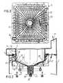
- Fig. 1 is perspective view of a deep-frying device according to the invention, with parts broken away.
- Fig. 2 is a part sectional view of the device of Fig. 1, according to a plane transverse to the frontside thereof.
- Fig. 3 is a bottom view of only the container of the deep-frying device, according to line III-III in Fig. 2.
- Fig. 4 shows another embodiment of a container according to the invention.
- The deep-
frying device 1 of Fig. 1 comprises aframe 2 in the form of a case, which at the front side is provided with a pivoting door 3. In the case 2 a horizontal mounting surface 4 is formed, in which acontainer 5 for deep-frying fat is mounted. According to the invention the container is made by casting from an aluminium alloy. Aflange 13 is cast to the container. Thecontainer 5 rests with theflange 13 on the mounting surface 4, and is connected therewith by means of bolts. Theframe 2 further comprises an upper surface 6, a downfolded edge 7 of which engages in the opening of thecontainer 5. Below the bottom surface of the container 5 a gas burner 8 is positioned. Gas is supplied to this burner from a gas conduit 10 through a control valve. - At the front side of the case 2 a number of
controls 11 known as such are provided, such as controls for adjusting the desired temperature of the deep-frying fat, and controls for a pilot flame. - The combustion gases produced by the gas burner 8, which gases are shown with
arrows 17 in Figs. 1 and 2, are discharged from the case bydischarging means 15. Thedeepfrying device 1 can be positioned under an exhaust hood, further discharging the combustion gases out. - The discharge means 15 comprise a combustion gas case 16 extending around the container.
- The
bottom surface 19 of thecontainer 5 slopes downward to the middle. In the middle of the bottom surface asink hole 18 is formed, in which acrumb tray 21 is placed. Small parts of the products to be fried which remain in the container accumulate in thecrumb tray 21 which can be taken out of thesink hole 18 and emptied regularly. Under in the sink hole 18 ascrew plug 20 is arranged. When the fat has to be replaced thescrew plug 20 is unscrewed, whereafter the fluid fat in the container can flow into a bucket positioned below the container. Thisbucket 12 is shown in Fig. 1 with broken lines. - As the container of the deep-frying device according to the invention is cast, the
corners 28 therein simply can be made rounded. For cleaning the container after draining of the fat, this is very favourable. - The
inside surface 27 of the container is hardened with a surface treatment known as such. This treatment, for aluminium known under the name "hard-coating", provides a scratchproof and wear-resistant inner surface. Furthermore, the aluminium treated in this way is insensitive for corrosion by the deep-frying fat. - To the
bottom surface 19 of thecontainer 5 surfacearea increasing elements 22 are cast. For instance these elements can be pens or ribs. According to the preferred embodiment shown in the Figures, the surfacearea increasing elements 22 are formed byribs 23 extending in radial direction. These ribs provide a very good heat exchange between the hot combustion gases of the gas burner 8 and the wall of thecontainer 5. - In Fig. 2 furthermore is shown that in the container 5 a
support 24 is cast, in which channels are drilled for receivingtemperature sensors - The
container 35 shown in section in Fig. 4, substantially corresponds to thecontainer 5 of thedevice 1 described above. Thecontainer 35 also comprises amounting flange 36, with which it can be mounted in a frame. With this preferred embodiment awall 37 is cast to themounting flange 36, whichwall 37 extends over a considerable part of the periphery of the container, to below the level of the bottom surface thereof. Thiswall 37 functions as the wall 16 of the combustion gas case in the device of Fig. 1. By embodying thecontainer 35 in this way, the number of parts of the deep-frying device according to the invention is reduced, so that the assembling and, because of that, the manufacturing costs of the device according to the invention can be reduced. - Although the examplary embodiments of the deep-frying device according to the invention have a container with a rectangular ground form, the container can also be formed with a round ground form, as is also current.
Claims (2)
Applications Claiming Priority (2)
| Application Number | Priority Date | Filing Date | Title |
|---|---|---|---|
| NL8401038ANL8401038A (en) | 1984-04-02 | 1984-04-02 | DEEP FRYER. |
| NL8401038 | 1984-04-02 |
Publications (2)
| Publication Number | Publication Date |
|---|---|
| EP0159750A1 EP0159750A1 (en) | 1985-10-30 |
| EP0159750B1true EP0159750B1 (en) | 1989-10-11 |
Family
ID=19843743
Family Applications (1)
| Application Number | Title | Priority Date | Filing Date |
|---|---|---|---|
| EP19850200513ExpiredEP0159750B1 (en) | 1984-04-02 | 1985-04-02 | Deep-frying device |
Country Status (3)
| Country | Link |
|---|---|
| EP (1) | EP0159750B1 (en) |
| DE (1) | DE3573523D1 (en) |
| NL (1) | NL8401038A (en) |
Families Citing this family (5)
| Publication number | Priority date | Publication date | Assignee | Title |
|---|---|---|---|---|
| NL192814C (en)* | 1990-10-02 | 2000-01-28 | Suplacon Bv | Frying device. |
| DE69412416T2 (en)* | 1993-10-21 | 1998-12-24 | Hobart Corp., Troy, Ohio | Pasta cooker |
| JP3629129B2 (en) | 1997-11-26 | 2005-03-16 | エイケン工業株式会社 | Liquid heating device |
| JP2000121274A (en) | 1998-10-19 | 2000-04-28 | Eiken Industries Co Ltd | Liquid heating device |
| US6601578B1 (en) | 1998-11-24 | 2003-08-05 | Eiken Industries Co., Ltd. | Liquid heating apparatus |
Family Cites Families (6)
| Publication number | Priority date | Publication date | Assignee | Title |
|---|---|---|---|---|
| US1397536A (en)* | 1921-06-25 | 1921-11-22 | Alfred C Moork | Kettle |
| GB436972A (en)* | 1934-05-08 | 1935-10-22 | Albert Edward Wilkinson | Improvements in and relating to fish frying and like cooking pans |
| FR901641A (en)* | 1943-09-20 | 1945-08-01 | Bourgeat Aluminium Dauphinois | Process for manufacturing laminated kitchen utensils with undeformable base in pure aluminum |
| GB962549A (en)* | 1960-01-19 | 1964-07-01 | Jack Stanley Lewis Kerr | Improvements in and relating to frying equipment |
| NL6508737A (en)* | 1965-07-07 | 1967-01-09 | ||
| CH608182A5 (en)* | 1976-03-01 | 1978-12-29 | Aro Sa | Deep-fat fryer |
- 1984
- 1984-04-02NLNL8401038Apatent/NL8401038A/ennot_activeApplication Discontinuation
- 1985
- 1985-04-02EPEP19850200513patent/EP0159750B1/ennot_activeExpired
- 1985-04-02DEDE8585200513Tpatent/DE3573523D1/ennot_activeExpired
Also Published As
| Publication number | Publication date |
|---|---|
| NL8401038A (en) | 1985-11-01 |
| DE3573523D1 (en) | 1989-11-16 |
| EP0159750A1 (en) | 1985-10-30 |
Similar Documents
| Publication | Publication Date | Title |
|---|---|---|
| RU2726768C2 (en) | Gas deep fryer with uniform heat exchange and improved access for cleaning | |
| US5211105A (en) | Smokeless and scorchless grill pan | |
| US5125393A (en) | Stove top vessel with energy conserving casing | |
| KR100243527B1 (en) | Fry cooker | |
| US6002111A (en) | Heating device for foodstuffs, particularly for frying, with an outer bowl | |
| US7538300B1 (en) | Polygonal cooking apparatus with a pressurizable condensate jacket | |
| EP0159750B1 (en) | Deep-frying device | |
| KR100246983B1 (en) | Fryer | |
| US20020023544A1 (en) | Multipurpose fryer | |
| US3982479A (en) | Energy saving cooking utensil | |
| CA2157684C (en) | Heat distributing apparatus for gas barbecues | |
| US6073541A (en) | Stock making kettle | |
| CN210961468U (en) | High-efficient radiating multi-functional cooking utensil | |
| EP0095014A1 (en) | Improvements relating to cooking utensils | |
| CN221599076U (en) | Novel oil-saving round frying stove | |
| CN217408463U (en) | Container assembly and heating device | |
| NO791089L (en) | DEVICE FOR FRYING FOOD. | |
| CN222425840U (en) | Water supply device and noodle cooking stove | |
| JPS6316359Y2 (en) | ||
| KR100554663B1 (en) | Water-cooled yakiniku apparatus using convection | |
| KR950010263Y1 (en) | Commercial Cooker | |
| KR200353931Y1 (en) | Water cooled roasted meet appratus using a convection current | |
| KR100408843B1 (en) | Meat Panael of Elvan | |
| KR200252930Y1 (en) | Raw Meat Roaster as Pottery | |
| KR890007192Y1 (en) | Pan |
Legal Events
| Date | Code | Title | Description |
|---|---|---|---|
| PUAI | Public reference made under article 153(3) epc to a published international application that has entered the european phase | Free format text:ORIGINAL CODE: 0009012 | |
| AK | Designated contracting states | Designated state(s):BE CH DE FR GB LI NL | |
| 17P | Request for examination filed | Effective date:19860219 | |
| 17Q | First examination report despatched | Effective date:19861208 | |
| RAP1 | Party data changed (applicant data changed or rights of an application transferred) | Owner name:ATAG KEUKENTECHNIEK B.V. | |
| GRAA | (expected) grant | Free format text:ORIGINAL CODE: 0009210 | |
| AK | Designated contracting states | Kind code of ref document:B1 Designated state(s):BE CH DE FR GB LI NL | |
| REF | Corresponds to: | Ref document number:3573523 Country of ref document:DE Date of ref document:19891116 | |
| ET | Fr: translation filed | ||
| PGFP | Annual fee paid to national office [announced via postgrant information from national office to epo] | Ref country code:CH Payment date:19900521 Year of fee payment:6 | |
| PGFP | Annual fee paid to national office [announced via postgrant information from national office to epo] | Ref country code:FR Payment date:19900528 Year of fee payment:6 | |
| PGFP | Annual fee paid to national office [announced via postgrant information from national office to epo] | Ref country code:GB Payment date:19900529 Year of fee payment:6 | |
| PLBE | No opposition filed within time limit | Free format text:ORIGINAL CODE: 0009261 | |
| STAA | Information on the status of an ep patent application or granted ep patent | Free format text:STATUS: NO OPPOSITION FILED WITHIN TIME LIMIT | |
| 26N | No opposition filed | ||
| PG25 | Lapsed in a contracting state [announced via postgrant information from national office to epo] | Ref country code:GB Effective date:19910402 | |
| PG25 | Lapsed in a contracting state [announced via postgrant information from national office to epo] | Ref country code:LI Effective date:19910430 Ref country code:CH Effective date:19910430 | |
| GBPC | Gb: european patent ceased through non-payment of renewal fee | ||
| PG25 | Lapsed in a contracting state [announced via postgrant information from national office to epo] | Ref country code:FR Effective date:19911230 | |
| REG | Reference to a national code | Ref country code:CH Ref legal event code:PL | |
| REG | Reference to a national code | Ref country code:FR Ref legal event code:ST | |
| PGFP | Annual fee paid to national office [announced via postgrant information from national office to epo] | Ref country code:NL Payment date:19920430 Year of fee payment:8 | |
| PGFP | Annual fee paid to national office [announced via postgrant information from national office to epo] | Ref country code:BE Payment date:19920515 Year of fee payment:8 | |
| PGFP | Annual fee paid to national office [announced via postgrant information from national office to epo] | Ref country code:DE Payment date:19920601 Year of fee payment:8 | |
| PG25 | Lapsed in a contracting state [announced via postgrant information from national office to epo] | Ref country code:BE Effective date:19930430 | |
| BERE | Be: lapsed | Owner name:ATAG KEUKENTECHNIEK B.V. Effective date:19930430 | |
| PG25 | Lapsed in a contracting state [announced via postgrant information from national office to epo] | Ref country code:NL Effective date:19931101 | |
| NLV4 | Nl: lapsed or anulled due to non-payment of the annual fee | ||
| PG25 | Lapsed in a contracting state [announced via postgrant information from national office to epo] | Ref country code:DE Effective date:19940101 |