EP0158014A1 - Hip prosthesis - Google Patents
Hip prosthesisDownload PDFInfo
- Publication number
- EP0158014A1 EP0158014A1EP85100943AEP85100943AEP0158014A1EP 0158014 A1EP0158014 A1EP 0158014A1EP 85100943 AEP85100943 AEP 85100943AEP 85100943 AEP85100943 AEP 85100943AEP 0158014 A1EP0158014 A1EP 0158014A1
- Authority
- EP
- European Patent Office
- Prior art keywords
- prosthesis
- shaft
- neck
- longitudinal axis
- hip joint
- Prior art date
- Legal status (The legal status is an assumption and is not a legal conclusion. Google has not performed a legal analysis and makes no representation as to the accuracy of the status listed.)
- Granted
Links
- 230000007704transitionEffects0.000claimsabstractdescription13
- 210000000988bone and boneAnatomy0.000claimsabstractdescription11
- 230000037431insertionEffects0.000claimsabstractdescription7
- 238000003780insertionMethods0.000claimsabstractdescription7
- 210000004394hip jointAnatomy0.000claimsabstractdescription6
- 210000001624hipAnatomy0.000claims2
- 230000000284resting effectEffects0.000claims1
- 238000002271resectionMethods0.000abstractdescription7
- 241001517013Calidris pugnaxSpecies0.000abstractdescription5
- 241001517019PhilomachusSpecies0.000abstract1
- 210000000689upper legAnatomy0.000description3
- 241000309551Arthraxon hispidusSpecies0.000description2
- 210000002414legAnatomy0.000description2
- 230000000295complement effectEffects0.000description1
- 230000001054cortical effectEffects0.000description1
- 210000005257cortical tissueAnatomy0.000description1
- 210000002436femur neckAnatomy0.000description1
- 230000035515penetrationEffects0.000description1
Images
Classifications
- A—HUMAN NECESSITIES
- A61—MEDICAL OR VETERINARY SCIENCE; HYGIENE
- A61F—FILTERS IMPLANTABLE INTO BLOOD VESSELS; PROSTHESES; DEVICES PROVIDING PATENCY TO, OR PREVENTING COLLAPSING OF, TUBULAR STRUCTURES OF THE BODY, e.g. STENTS; ORTHOPAEDIC, NURSING OR CONTRACEPTIVE DEVICES; FOMENTATION; TREATMENT OR PROTECTION OF EYES OR EARS; BANDAGES, DRESSINGS OR ABSORBENT PADS; FIRST-AID KITS
- A61F2/00—Filters implantable into blood vessels; Prostheses, i.e. artificial substitutes or replacements for parts of the body; Appliances for connecting them with the body; Devices providing patency to, or preventing collapsing of, tubular structures of the body, e.g. stents
- A61F2/02—Prostheses implantable into the body
- A61F2/30—Joints
- A61F2/30721—Accessories
- A61F2/30728—Collars; Bone edge protectors
- A—HUMAN NECESSITIES
- A61—MEDICAL OR VETERINARY SCIENCE; HYGIENE
- A61F—FILTERS IMPLANTABLE INTO BLOOD VESSELS; PROSTHESES; DEVICES PROVIDING PATENCY TO, OR PREVENTING COLLAPSING OF, TUBULAR STRUCTURES OF THE BODY, e.g. STENTS; ORTHOPAEDIC, NURSING OR CONTRACEPTIVE DEVICES; FOMENTATION; TREATMENT OR PROTECTION OF EYES OR EARS; BANDAGES, DRESSINGS OR ABSORBENT PADS; FIRST-AID KITS
- A61F2/00—Filters implantable into blood vessels; Prostheses, i.e. artificial substitutes or replacements for parts of the body; Appliances for connecting them with the body; Devices providing patency to, or preventing collapsing of, tubular structures of the body, e.g. stents
- A61F2/02—Prostheses implantable into the body
- A61F2/30—Joints
- A61F2/32—Joints for the hip
- A61F2/36—Femoral heads ; Femoral endoprostheses
- A61F2/3662—Femoral shafts
- A61F2/3676—Distal or diaphyseal parts of shafts
- A—HUMAN NECESSITIES
- A61—MEDICAL OR VETERINARY SCIENCE; HYGIENE
- A61F—FILTERS IMPLANTABLE INTO BLOOD VESSELS; PROSTHESES; DEVICES PROVIDING PATENCY TO, OR PREVENTING COLLAPSING OF, TUBULAR STRUCTURES OF THE BODY, e.g. STENTS; ORTHOPAEDIC, NURSING OR CONTRACEPTIVE DEVICES; FOMENTATION; TREATMENT OR PROTECTION OF EYES OR EARS; BANDAGES, DRESSINGS OR ABSORBENT PADS; FIRST-AID KITS
- A61F2/00—Filters implantable into blood vessels; Prostheses, i.e. artificial substitutes or replacements for parts of the body; Appliances for connecting them with the body; Devices providing patency to, or preventing collapsing of, tubular structures of the body, e.g. stents
- A61F2/02—Prostheses implantable into the body
- A61F2/30—Joints
- A61F2/46—Special tools for implanting artificial joints
- A61F2/4603—Special tools for implanting artificial joints for insertion or extraction of endoprosthetic joints or of accessories thereof
- A61F2/4607—Special tools for implanting artificial joints for insertion or extraction of endoprosthetic joints or of accessories thereof of hip femoral endoprostheses
- A—HUMAN NECESSITIES
- A61—MEDICAL OR VETERINARY SCIENCE; HYGIENE
- A61F—FILTERS IMPLANTABLE INTO BLOOD VESSELS; PROSTHESES; DEVICES PROVIDING PATENCY TO, OR PREVENTING COLLAPSING OF, TUBULAR STRUCTURES OF THE BODY, e.g. STENTS; ORTHOPAEDIC, NURSING OR CONTRACEPTIVE DEVICES; FOMENTATION; TREATMENT OR PROTECTION OF EYES OR EARS; BANDAGES, DRESSINGS OR ABSORBENT PADS; FIRST-AID KITS
- A61F2/00—Filters implantable into blood vessels; Prostheses, i.e. artificial substitutes or replacements for parts of the body; Appliances for connecting them with the body; Devices providing patency to, or preventing collapsing of, tubular structures of the body, e.g. stents
- A61F2/02—Prostheses implantable into the body
- A61F2/30—Joints
- A61F2002/30001—Additional features of subject-matter classified in A61F2/28, A61F2/30 and subgroups thereof
- A61F2002/30108—Shapes
- A61F2002/3011—Cross-sections or two-dimensional shapes
- A61F2002/30112—Rounded shapes, e.g. with rounded corners
- A61F2002/30131—Rounded shapes, e.g. with rounded corners horseshoe- or crescent- or C-shaped or U-shaped
- A—HUMAN NECESSITIES
- A61—MEDICAL OR VETERINARY SCIENCE; HYGIENE
- A61F—FILTERS IMPLANTABLE INTO BLOOD VESSELS; PROSTHESES; DEVICES PROVIDING PATENCY TO, OR PREVENTING COLLAPSING OF, TUBULAR STRUCTURES OF THE BODY, e.g. STENTS; ORTHOPAEDIC, NURSING OR CONTRACEPTIVE DEVICES; FOMENTATION; TREATMENT OR PROTECTION OF EYES OR EARS; BANDAGES, DRESSINGS OR ABSORBENT PADS; FIRST-AID KITS
- A61F2/00—Filters implantable into blood vessels; Prostheses, i.e. artificial substitutes or replacements for parts of the body; Appliances for connecting them with the body; Devices providing patency to, or preventing collapsing of, tubular structures of the body, e.g. stents
- A61F2/02—Prostheses implantable into the body
- A61F2/30—Joints
- A61F2002/30001—Additional features of subject-matter classified in A61F2/28, A61F2/30 and subgroups thereof
- A61F2002/30108—Shapes
- A61F2002/3011—Cross-sections or two-dimensional shapes
- A61F2002/30112—Rounded shapes, e.g. with rounded corners
- A61F2002/30136—Rounded shapes, e.g. with rounded corners undulated or wavy, e.g. serpentine-shaped or zigzag-shaped
- A—HUMAN NECESSITIES
- A61—MEDICAL OR VETERINARY SCIENCE; HYGIENE
- A61F—FILTERS IMPLANTABLE INTO BLOOD VESSELS; PROSTHESES; DEVICES PROVIDING PATENCY TO, OR PREVENTING COLLAPSING OF, TUBULAR STRUCTURES OF THE BODY, e.g. STENTS; ORTHOPAEDIC, NURSING OR CONTRACEPTIVE DEVICES; FOMENTATION; TREATMENT OR PROTECTION OF EYES OR EARS; BANDAGES, DRESSINGS OR ABSORBENT PADS; FIRST-AID KITS
- A61F2/00—Filters implantable into blood vessels; Prostheses, i.e. artificial substitutes or replacements for parts of the body; Appliances for connecting them with the body; Devices providing patency to, or preventing collapsing of, tubular structures of the body, e.g. stents
- A61F2/02—Prostheses implantable into the body
- A61F2/30—Joints
- A61F2002/30001—Additional features of subject-matter classified in A61F2/28, A61F2/30 and subgroups thereof
- A61F2002/30108—Shapes
- A61F2002/3011—Cross-sections or two-dimensional shapes
- A61F2002/30138—Convex polygonal shapes
- A61F2002/30158—Convex polygonal shapes trapezoidal
- A—HUMAN NECESSITIES
- A61—MEDICAL OR VETERINARY SCIENCE; HYGIENE
- A61F—FILTERS IMPLANTABLE INTO BLOOD VESSELS; PROSTHESES; DEVICES PROVIDING PATENCY TO, OR PREVENTING COLLAPSING OF, TUBULAR STRUCTURES OF THE BODY, e.g. STENTS; ORTHOPAEDIC, NURSING OR CONTRACEPTIVE DEVICES; FOMENTATION; TREATMENT OR PROTECTION OF EYES OR EARS; BANDAGES, DRESSINGS OR ABSORBENT PADS; FIRST-AID KITS
- A61F2/00—Filters implantable into blood vessels; Prostheses, i.e. artificial substitutes or replacements for parts of the body; Appliances for connecting them with the body; Devices providing patency to, or preventing collapsing of, tubular structures of the body, e.g. stents
- A61F2/02—Prostheses implantable into the body
- A61F2/30—Joints
- A61F2002/30001—Additional features of subject-matter classified in A61F2/28, A61F2/30 and subgroups thereof
- A61F2002/30316—The prosthesis having different structural features at different locations within the same prosthesis; Connections between prosthetic parts; Special structural features of bone or joint prostheses not otherwise provided for
- A61F2002/30535—Special structural features of bone or joint prostheses not otherwise provided for
- A61F2002/30594—Special structural features of bone or joint prostheses not otherwise provided for slotted, e.g. radial or meridian slot ending in a polar aperture, non-polar slots, horizontal or arcuate slots
- A—HUMAN NECESSITIES
- A61—MEDICAL OR VETERINARY SCIENCE; HYGIENE
- A61F—FILTERS IMPLANTABLE INTO BLOOD VESSELS; PROSTHESES; DEVICES PROVIDING PATENCY TO, OR PREVENTING COLLAPSING OF, TUBULAR STRUCTURES OF THE BODY, e.g. STENTS; ORTHOPAEDIC, NURSING OR CONTRACEPTIVE DEVICES; FOMENTATION; TREATMENT OR PROTECTION OF EYES OR EARS; BANDAGES, DRESSINGS OR ABSORBENT PADS; FIRST-AID KITS
- A61F2/00—Filters implantable into blood vessels; Prostheses, i.e. artificial substitutes or replacements for parts of the body; Appliances for connecting them with the body; Devices providing patency to, or preventing collapsing of, tubular structures of the body, e.g. stents
- A61F2/02—Prostheses implantable into the body
- A61F2/30—Joints
- A61F2/30721—Accessories
- A61F2/30728—Collars; Bone edge protectors
- A61F2002/30729—Separate collars
- A—HUMAN NECESSITIES
- A61—MEDICAL OR VETERINARY SCIENCE; HYGIENE
- A61F—FILTERS IMPLANTABLE INTO BLOOD VESSELS; PROSTHESES; DEVICES PROVIDING PATENCY TO, OR PREVENTING COLLAPSING OF, TUBULAR STRUCTURES OF THE BODY, e.g. STENTS; ORTHOPAEDIC, NURSING OR CONTRACEPTIVE DEVICES; FOMENTATION; TREATMENT OR PROTECTION OF EYES OR EARS; BANDAGES, DRESSINGS OR ABSORBENT PADS; FIRST-AID KITS
- A61F2/00—Filters implantable into blood vessels; Prostheses, i.e. artificial substitutes or replacements for parts of the body; Appliances for connecting them with the body; Devices providing patency to, or preventing collapsing of, tubular structures of the body, e.g. stents
- A61F2/02—Prostheses implantable into the body
- A61F2/30—Joints
- A61F2/30767—Special external or bone-contacting surface, e.g. coating for improving bone ingrowth
- A61F2/30771—Special external or bone-contacting surface, e.g. coating for improving bone ingrowth applied in original prostheses, e.g. holes or grooves
- A61F2002/30795—Blind bores, e.g. of circular cross-section
- A—HUMAN NECESSITIES
- A61—MEDICAL OR VETERINARY SCIENCE; HYGIENE
- A61F—FILTERS IMPLANTABLE INTO BLOOD VESSELS; PROSTHESES; DEVICES PROVIDING PATENCY TO, OR PREVENTING COLLAPSING OF, TUBULAR STRUCTURES OF THE BODY, e.g. STENTS; ORTHOPAEDIC, NURSING OR CONTRACEPTIVE DEVICES; FOMENTATION; TREATMENT OR PROTECTION OF EYES OR EARS; BANDAGES, DRESSINGS OR ABSORBENT PADS; FIRST-AID KITS
- A61F2/00—Filters implantable into blood vessels; Prostheses, i.e. artificial substitutes or replacements for parts of the body; Appliances for connecting them with the body; Devices providing patency to, or preventing collapsing of, tubular structures of the body, e.g. stents
- A61F2/02—Prostheses implantable into the body
- A61F2/30—Joints
- A61F2/30767—Special external or bone-contacting surface, e.g. coating for improving bone ingrowth
- A61F2/30771—Special external or bone-contacting surface, e.g. coating for improving bone ingrowth applied in original prostheses, e.g. holes or grooves
- A61F2002/3082—Grooves
- A—HUMAN NECESSITIES
- A61—MEDICAL OR VETERINARY SCIENCE; HYGIENE
- A61F—FILTERS IMPLANTABLE INTO BLOOD VESSELS; PROSTHESES; DEVICES PROVIDING PATENCY TO, OR PREVENTING COLLAPSING OF, TUBULAR STRUCTURES OF THE BODY, e.g. STENTS; ORTHOPAEDIC, NURSING OR CONTRACEPTIVE DEVICES; FOMENTATION; TREATMENT OR PROTECTION OF EYES OR EARS; BANDAGES, DRESSINGS OR ABSORBENT PADS; FIRST-AID KITS
- A61F2/00—Filters implantable into blood vessels; Prostheses, i.e. artificial substitutes or replacements for parts of the body; Appliances for connecting them with the body; Devices providing patency to, or preventing collapsing of, tubular structures of the body, e.g. stents
- A61F2/02—Prostheses implantable into the body
- A61F2/30—Joints
- A61F2/30767—Special external or bone-contacting surface, e.g. coating for improving bone ingrowth
- A61F2/30771—Special external or bone-contacting surface, e.g. coating for improving bone ingrowth applied in original prostheses, e.g. holes or grooves
- A61F2002/30841—Sharp anchoring protrusions for impaction into the bone, e.g. sharp pins, spikes
- A61F2002/30845—Sharp anchoring protrusions for impaction into the bone, e.g. sharp pins, spikes with cutting edges
- A—HUMAN NECESSITIES
- A61—MEDICAL OR VETERINARY SCIENCE; HYGIENE
- A61F—FILTERS IMPLANTABLE INTO BLOOD VESSELS; PROSTHESES; DEVICES PROVIDING PATENCY TO, OR PREVENTING COLLAPSING OF, TUBULAR STRUCTURES OF THE BODY, e.g. STENTS; ORTHOPAEDIC, NURSING OR CONTRACEPTIVE DEVICES; FOMENTATION; TREATMENT OR PROTECTION OF EYES OR EARS; BANDAGES, DRESSINGS OR ABSORBENT PADS; FIRST-AID KITS
- A61F2/00—Filters implantable into blood vessels; Prostheses, i.e. artificial substitutes or replacements for parts of the body; Appliances for connecting them with the body; Devices providing patency to, or preventing collapsing of, tubular structures of the body, e.g. stents
- A61F2/02—Prostheses implantable into the body
- A61F2/30—Joints
- A61F2/30767—Special external or bone-contacting surface, e.g. coating for improving bone ingrowth
- A61F2/30771—Special external or bone-contacting surface, e.g. coating for improving bone ingrowth applied in original prostheses, e.g. holes or grooves
- A61F2002/30878—Special external or bone-contacting surface, e.g. coating for improving bone ingrowth applied in original prostheses, e.g. holes or grooves with non-sharp protrusions, for instance contacting the bone for anchoring, e.g. keels, pegs, pins, posts, shanks, stems, struts
- A61F2002/30879—Ribs
- A—HUMAN NECESSITIES
- A61—MEDICAL OR VETERINARY SCIENCE; HYGIENE
- A61F—FILTERS IMPLANTABLE INTO BLOOD VESSELS; PROSTHESES; DEVICES PROVIDING PATENCY TO, OR PREVENTING COLLAPSING OF, TUBULAR STRUCTURES OF THE BODY, e.g. STENTS; ORTHOPAEDIC, NURSING OR CONTRACEPTIVE DEVICES; FOMENTATION; TREATMENT OR PROTECTION OF EYES OR EARS; BANDAGES, DRESSINGS OR ABSORBENT PADS; FIRST-AID KITS
- A61F2/00—Filters implantable into blood vessels; Prostheses, i.e. artificial substitutes or replacements for parts of the body; Appliances for connecting them with the body; Devices providing patency to, or preventing collapsing of, tubular structures of the body, e.g. stents
- A61F2/02—Prostheses implantable into the body
- A61F2/30—Joints
- A61F2/32—Joints for the hip
- A61F2/36—Femoral heads ; Femoral endoprostheses
- A61F2/3609—Femoral heads or necks; Connections of endoprosthetic heads or necks to endoprosthetic femoral shafts
- A61F2002/3625—Necks
- A61F2002/3631—Necks with an integral complete or partial peripheral collar or bearing shoulder at its base
- A—HUMAN NECESSITIES
- A61—MEDICAL OR VETERINARY SCIENCE; HYGIENE
- A61F—FILTERS IMPLANTABLE INTO BLOOD VESSELS; PROSTHESES; DEVICES PROVIDING PATENCY TO, OR PREVENTING COLLAPSING OF, TUBULAR STRUCTURES OF THE BODY, e.g. STENTS; ORTHOPAEDIC, NURSING OR CONTRACEPTIVE DEVICES; FOMENTATION; TREATMENT OR PROTECTION OF EYES OR EARS; BANDAGES, DRESSINGS OR ABSORBENT PADS; FIRST-AID KITS
- A61F2230/00—Geometry of prostheses classified in groups A61F2/00 - A61F2/26 or A61F2/82 or A61F9/00 or A61F11/00 or subgroups thereof
- A61F2230/0002—Two-dimensional shapes, e.g. cross-sections
- A61F2230/0004—Rounded shapes, e.g. with rounded corners
- A61F2230/0013—Horseshoe-shaped, e.g. crescent-shaped, C-shaped, U-shaped
- A—HUMAN NECESSITIES
- A61—MEDICAL OR VETERINARY SCIENCE; HYGIENE
- A61F—FILTERS IMPLANTABLE INTO BLOOD VESSELS; PROSTHESES; DEVICES PROVIDING PATENCY TO, OR PREVENTING COLLAPSING OF, TUBULAR STRUCTURES OF THE BODY, e.g. STENTS; ORTHOPAEDIC, NURSING OR CONTRACEPTIVE DEVICES; FOMENTATION; TREATMENT OR PROTECTION OF EYES OR EARS; BANDAGES, DRESSINGS OR ABSORBENT PADS; FIRST-AID KITS
- A61F2230/00—Geometry of prostheses classified in groups A61F2/00 - A61F2/26 or A61F2/82 or A61F9/00 or A61F11/00 or subgroups thereof
- A61F2230/0002—Two-dimensional shapes, e.g. cross-sections
- A61F2230/0017—Angular shapes
- A61F2230/0026—Angular shapes trapezoidal
Definitions
- the inventionrelates to a hip joint prosthesis with a straight, conically widening, leaf-like shaft, the leaf sides of which are covered at least in the proximal part of the shaft with a rib structure parallel to its longitudinal axis, a cervical collar being able to be pushed onto the shaft in the transition region to the prosthesis neck.
- Such a shaftis known from DE-OS 32 18 538; the removable cervical collar, the removability of which, when the prosthesis is inserted, is intended to facilitate removal of the shaft from the bone in the event of reoperations, is pushed from medial to lateral onto the shaft of the prosthesis fully inserted into the femur.
- prosthetic stemswhich are anchored in the femur, are to be additionally supported on the edge of the surgical opening with the help of a collar or a frill, it is necessary for effective support that the support surface of the collar and the resection plane on the prosthesis neck run as parallel as possible to each other and beyond have the "correct" height with respect to a reference point, so that when the prosthesis is inserted, for example, the joint head is held at the correct level relative to the trochanter.
- these two requirementshave the consequence that the resection cut is very accurate in the correct one Height and must be carried out at the correct angle, which makes the work of the surgeon considerably more difficult.
- the object of the inventionis therefore to provide a prosthesis in which inaccuracies in the position of the resection incision can be corrected to a certain extent.
- This objectis achieved according to the invention in that the cervical collar has an insertion opening, the shape and dimensions of which are adapted to the transition region to the prosthesis neck in such a way that the cervical collar can be pushed onto the shaft from distal in the direction of the longitudinal axis.
- a conical clamp fitis provided between the cervical collar and the prosthesis neck in the medial, rib-free part of the transition area; Furthermore, the driving in of the shaft, which is supported by jamming essentially along its conical shape, and the fixing of the neck brace can be facilitated if two driving holes are located on a horizontal shoulder at the proximal end of the shaft are provided, one of which is arranged at least almost in the region of the longitudinal axis of the shaft, while the other is located as far as possible medially offset near the shoulder transition in the prosthesis neck.
- the insertion opening located mediallyserves primarily to wedge the ruff onto the conical clamping seat in the medial transition area to the prosthesis neck.
- the fit of the prosthesis in or on the bonecan be additionally improved if the support surface of the cervical collar intended for bearing on the bone is covered with sharp wedge-like teeth in its part located medially.
- the leaf sides of the shaft 1, which - as shown in FIG. 2 - extend conically over the entire shaft height - measured along the central axis 2 -are provided with a surface structure consisting of grooves which extend parallel to the central axis 2 and which allow bone tissue to grow promotes; this structure extends medially to a point 3 at which a horizontal shoulder 4 merges into a prosthesis neck 6.
- An essentially spherical joint head 13is placed on the prosthesis neck 6 adjoining this shoulder 4.
- the axis 14 of the prosthesis neck 6intersects the longitudinal center axis of the shaft 1 at an angle which substantially corresponds to the angle between the femoral neck and the femoral axis of a natural hip joint and is in this case about 45 0th
- the medial narrow side 12initially runs conically from the distal end 15 to the central axis 2 and then merges into an arc, the course of which is largely adapted to the calcar arch.
- a trochanter wing 8which ends in the horizontal shoulder 4, protrudes from the likewise conical lateral narrow side 7 of the shaft 1.
- the opening 10has the task of securing the fit of a neck brace 11 on the shaft 1 and its tight fit on the cortical tissue of the edge of the surgical opening with the aid of the impact instrument.
- the essentially horseshoe-shaped neck brace 11has an insertion opening 17 which is adapted in shape and dimensions to the shaft contours in the transition area between the surface structure and the prosthesis neck; the grooves 5 of the structure running parallel to the central axis 2, as already mentioned, end medially in a "last" groove 5 'which extends distally from point 3 parallel to the central axis.
- the "smooth" transition areamedial to this groove 5 'forms a cone 16 (FIG. 3) with which the shaft merges into the somewhat thicker prosthesis neck 6.
- the insertion opening 17is provided in its lateral part with ribs 18 which are complementary to the grooves 5 and forms a cone 22 opposite the cone 16 in the medial part (FIG. 3).
- the contact surface or underside 19 (FIG. 5) of the cervical collar 11, which is provided in the medial part with sharp, wedge-like teeth 20 for penetration into the cortical "edge" of the surgical opening,can form different angles with the upper side 21.
- the top and bottom surfaces 21 and 19run parallel to one another, the counter-cone 22 extending relative to the bottom surface 19 such that it is laterally about 20 ° from a plane perpendicular to the prosthesis neck axis 14 is inclined distally.
- the angle of the resection planebecomes flatter against a horizontal, which reduces the risk of the neck brace 11 "slipping".
- the bottom side 19can form negative or positive angles with the top side 21, these two surfaces of the frill 11 running laterally apart at positive angles and converging towards one another at negative angles.
- a longitudinal slit 23is provided at the distal end 15 of the shaft 1 to adapt the distal shaft part to cavities in the femur bone of different widths, which permits elastic and / or plastic deformation of the distal shaft part; this longitudinal slot 23 is offset from the central axis 2. medially such that its lateral leg 24 - despite an expansion to the lateral / distal - is practically rigid and non-deformable and the entire deformation takes place in the medial leg 25.
Landscapes
- Health & Medical Sciences (AREA)
- Orthopedic Medicine & Surgery (AREA)
- Cardiology (AREA)
- Oral & Maxillofacial Surgery (AREA)
- Transplantation (AREA)
- Engineering & Computer Science (AREA)
- Biomedical Technology (AREA)
- Heart & Thoracic Surgery (AREA)
- Vascular Medicine (AREA)
- Life Sciences & Earth Sciences (AREA)
- Animal Behavior & Ethology (AREA)
- General Health & Medical Sciences (AREA)
- Public Health (AREA)
- Veterinary Medicine (AREA)
- Prostheses (AREA)
- Materials For Medical Uses (AREA)
Abstract
Description
Translated fromGermanDie Erfindung betrifft eine Hüftgelenkprothese mit einem geraden, sich konisch erweiternden, blattartigen Schaft, dessen Blattseiten mindestens im proximalen Schaftteil mit einer, zu seiner Längsachse parallelen Rippenstruktur bedeckt sind, wobei im Uebergangsbereich zum Prothesenhals eine Halskrause auf den Schaft aufschiebbar ist.The invention relates to a hip joint prosthesis with a straight, conically widening, leaf-like shaft, the leaf sides of which are covered at least in the proximal part of the shaft with a rib structure parallel to its longitudinal axis, a cervical collar being able to be pushed onto the shaft in the transition region to the prosthesis neck.
Ein derartiger Schaft ist aus der DE-OS 32 18 538 bekannt; die abnehmbare Halskrause, deren Abnehmbarkeit bei eingesetzter Prothese im Falle von Reoperationen das Entfernen des Schaftes aus dem Knochen erleichtern soll, wird dabei von medial nach lateral auf den vollständig in den Femurknochen eingesetzten Schaft der Prothese aufgeschoben.Such a shaft is known from DE-OS 32 18 538; the removable cervical collar, the removability of which, when the prosthesis is inserted, is intended to facilitate removal of the shaft from the bone in the event of reoperations, is pushed from medial to lateral onto the shaft of the prosthesis fully inserted into the femur.
Sollen Prothesenschäfte, die im Femur verankert sind, zusätzlich auf dem Rand der Operationsöffnung mit Hilfe eines Kragens oder einer Halskrause abgestützt werden, so ist es für eine wirksame Abstützung erforderlich, dass die Auflagefläche des Kragens und die Resektionsebene am Prothesenhals möglichst parallel zueinander verlaufen und darüberhinaus bezüglich eines Bezugspunktes die "richtige" Höhe haben, damit bei eingesetzter Prothese beispielsweise der Gelenkkopf relativ zum Trochanter auf dem richtigen Niveau gehalten wird. Diese beidenForderungen haben bei der Verwendung bisheriger Prothesen zur Folge, dass der Resektionsschnitt sehr genau in der richtige Höhe und unter dem richtigen Winkel ausgeführt werden muss, was die Arbeit des Operateurs erheblich erschwert.If prosthetic stems, which are anchored in the femur, are to be additionally supported on the edge of the surgical opening with the help of a collar or a frill, it is necessary for effective support that the support surface of the collar and the resection plane on the prosthesis neck run as parallel as possible to each other and beyond have the "correct" height with respect to a reference point, so that when the prosthesis is inserted, for example, the joint head is held at the correct level relative to the trochanter. When using previous prostheses, these two requirements have the consequence that the resection cut is very accurate in the correct one Height and must be carried out at the correct angle, which makes the work of the surgeon considerably more difficult.
Aufgabe der Erfindung ist es daher, eine Prothese zu schaffen, bei der nachträglich Ungenauigkeiten in der Lage des Resektionsschnittes in einem gewissen Umfang korrigiert werden können. Diese Aufgabe wird nach der Erfindung dadurch gelöst, dass die Halskrause eine Einschieböffnung aufweist, deren Form und Abmessungen an den Uebergangsbereich zum Prothesenhals derart angepasst sind, dass die Halskrause in Richtung der Längsachse von distal auf den Schaft aufschiebbar ist.The object of the invention is therefore to provide a prosthesis in which inaccuracies in the position of the resection incision can be corrected to a certain extent. This object is achieved according to the invention in that the cervical collar has an insertion opening, the shape and dimensions of which are adapted to the transition region to the prosthesis neck in such a way that the cervical collar can be pushed onto the shaft from distal in the direction of the longitudinal axis.
Auf diese Weise ist es möglich, einer Standard-Prothese, die gegebenenfalls auch ohne Halskrause verwendet werden kann bzw. einer bestimmten Schaftgrösse,einen ganzen Satz Halskrausen beizufügen, die unterschiedliche Dicken haben und/oder deren zur Auflage auf dem Knochen bestimmte Unterseite unterschiedliche Winkel mit der Prothesenhalsachse bilden. Aus diesem Satz Halskrausen kann der Operateur nach dem Resektionsschnitt die individuell am besten geeignete Halskrause auswählen, sie in Richtung der Längsachse auf den Schaft aufschieben und beim Einschlagen des Schaftes an diesem fixieren.In this way, it is possible to add a full set of cervical collars to a standard prosthesis, which can also be used without a cervical collar or a specific stem size, which have different thicknesses and / or whose underside, which is intended to rest on the bone, has different angles the axis of the prosthesis neck. From this set of cervical collars, the surgeon can select the most suitable cervical collar after the resection cut, slide it onto the shaft in the direction of the longitudinal axis and fix it to the shaft when it is driven in.
Für eine sichere Fixierung ist es vorteilhaft, wenn im medialen,rippenfreien Teil des Uebergangsbereichs ein konischer Klemmsitz zwischen Halskrause und Prothesenhals vorgesehen ist; weiterhin können das Einschlagen des Schaftes, der sich durch Verklemmen im wesentlichen längs seines konischen Verlaufs abstützt,und das Fixieren der Halskrause erleichtert werden, wenn auf einer horizontalen Schulter am proximalen Schaftende zwei Einschlagbohrungen vorgesehen sind, von denen die eine mindestens nahezu im Bereich der Längsachse des Schaftes angeordnet ist, während sich die andere möglichst weit nach medial versetzt nahe dem Uebergang der Schulter in dem Prothesenhals befindet. Die nach medial gelegene Einschlagöffnung dient dabei in erster Linie dazu, die Halskrause auf den konischen Klemmsitz im medialen Uebergangsbereich zum Prothesenhals aufzukeilen.For a secure fixation, it is advantageous if a conical clamp fit is provided between the cervical collar and the prosthesis neck in the medial, rib-free part of the transition area; Furthermore, the driving in of the shaft, which is supported by jamming essentially along its conical shape, and the fixing of the neck brace can be facilitated if two driving holes are located on a horizontal shoulder at the proximal end of the shaft are provided, one of which is arranged at least almost in the region of the longitudinal axis of the shaft, while the other is located as far as possible medially offset near the shoulder transition in the prosthesis neck. The insertion opening located medially serves primarily to wedge the ruff onto the conical clamping seat in the medial transition area to the prosthesis neck.
Um die "Steilheit" des Resektionsschnittes und damit die Gefahr des "Abrutschens" der Halskrause bzw. der Prothese nach medial zu verringern, ist es weiterhin vorteilhaft, wenn mindestens die zur Auflage auf dem Knochen bestimmte Auflagefläche der aufgeschobenen Halskrause gegen die Prothesenhalsachse um einen von der Senkrechten abweichenden Winkel geneigt ist.In order to reduce the "steepness" of the resection incision and thus the risk of "slipping" of the cervical collar or the prosthesis medially, it is further advantageous if at least the contact surface of the pushed-on cervical collar intended to rest on the bone against the prosthesis neck axis by one of the perpendicular deviating angle is inclined.
Schliesslich kann der Sitz der Prothese in bzw. auf dem Knochen zusätzlich verbessert werden, wenn die zur Auflage auf dem Knochen bestimmte Auflagefläche der Halskrause in ihrem nach medial gelegenen Teil mit scharfen keilartigen Zähnen belegt ist.Finally, the fit of the prosthesis in or on the bone can be additionally improved if the support surface of the cervical collar intended for bearing on the bone is covered with sharp wedge-like teeth in its part located medially.
Im folgenden wird die Erfindung anhand eines Ausführungsbeispiels im Zusammenhang mit der Zeichnung näher erläutert.
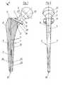
- Fig. 1 ist eine ventral/dorsal gesehene Ansicht der neuen Prothese;
- Fig. 2 gibt eine Ansicht von Fig. 1 von links wieder;
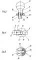
- Fig. 3 ist, teilweise im Schnitt, eine Ansicht in Richtung des Pfeiles A von Fig. l;
- Fig. 4 stellt eine Aufsicht auf Fig. 1 von oben dar, während
- Fig. 5 eine Aufsicht auf die Auflagefläche bzw. Unterseite einer Halskrause wiedergibt.
- 1 is a ventral / dorsal view of the new prosthesis;
- FIG. 2 shows a view of FIG. 1 from the left;
- Fig. 3 is, partly in section, a view in the direction of arrow A of Fig. 1;
- FIG. 4 illustrates a top view of FIG. 1 while
- Fig. 5 shows a top view of the support surface or underside of a ruff.
Die Blattseiten des Schaftes 1, die - wie in Fig. 2 gezeigt - über die ganze - längs der Mittelachse 2 gemessene - Schafthöhe konisch erweitert verlaufen, sind mit einer aus sich parallel zur Mittelachse 2 erstreckenden Rillen bestehenden Oberflächenstruktur versehen, die das Anwachsen von Knochengewebe fördert; diese Struktur reicht nach medial bis zu einem Punkt 3, in dem eine horizontale Schulter 4 in einen Prothesenhals 6 übergeht.The leaf sides of the
Auf den an diese Schulter 4 anschliessenden Prothesenhals 6 ist ein im wesentlichen kugelförmigen Gelenkkopf 13 aufgesetzt. Die Achse 14 des Prothesenhals 6 schneidet die Längsmittelachse des Schaftes 1 unter einem Winkel, der im wesentlichen dem Winkel zwischen dem Schenkelhals und der Femurachse eines natürlichen Hüftgelenks entspricht und im vorliegenden Fall etwa 450 beträgt.An essentially
Die mediale Schmalseite 12 verläuft zunächst vom distalen Ende 15 aus konisch zur Mittelachse 2 und geht anschliessend in einen Bogen über, der in seinem Verlauf weitgehend dem Calcar-Bogen angepasst ist.The medial
Aus der ebenfalls konisch verlaufenden lateralen Schmalseite 7 des Schaftes 1 springt - vom distalen Ende 15 aus etwas oberhalb 2/3 der Schafthöhe - in einem zunächst nach lateral gekrümmten Bogen ein Trochanterflügel 8 hervor, der in der horizontalen Schulter 4 endet. In ihr befinden sich zwei zueinander versetzte Einschlagöffnungen 9, 10 (Fig. 4) für den Einsatz eines Einschlaginstrumentes; während die linke, nahe der Mittelachse 2 angeordnete Einschlagöffnung 9 zum Einschlagen des Schaftes 1 in den Knochen dient, hat die Oeffnung 10 die Aufgabe, mit Hilfe-des Einschlaginstrumentes den Sitz einer Halskrause 11 auf dem Schaft 1 und ihren festen Sitz auf dem kortikalen.Gewebe des Randes der Operationsöffnung zu sichern.From the
Wie besonders aus Fig. 3 zu ersehen ist, hat die im wesentlichen hufeisenförmige Halskrause 11 eine Einschuböffnung 17, die in Form und Abmessungen an die Schaftkonturen im Uebergangsbereich zwischen der Oberflächenstruktur und dem Prothesenhals angepasst ist; die parallel zur Mittelachse 2 verlaufenden Rillen 5 der Struktur enden, wie bereits erwähnt, nach medial in einer sich vom Punkt 3 parallel zur Mittelachse nach distal erstreckenden "letzten" Rille 5'. Der "glatte" Uebergangsbereich medial dieser Rille 5' bildet einen Konus 16 (Fig. 3),mit dem der Schaft in den etwas dickeren Prothesenhals 6 übergeht. Entsprechend diesem Uebergangsbereich ist die Einschuböffnung 17 in ihrem lateralen Teil mit zu den Rillen 5 komplementär ausgebildeten Rippen 18 versehen und bildet im medialen Teil einen Gegenkonus 22 zum Konus 16 (Fig. 3).As can be seen particularly from FIG. 3, the essentially horseshoe-
Die Auflagefläche oder Unterseite 19 (Fig. 5) der Halskrause 11, die im medialen Teil mit scharfen, keilartigen Zähnen 20 für ein Eindringen in den kortikalen "Rand" der Operationsöffnung versehen ist, kann mit der Oberseite 21 unterschiedliche Winkel bilden.The contact surface or underside 19 (FIG. 5) of the
Bei der im Ausführungsbeispiel dargestellten "Normal-Form" der Halskrause 11 verlaufen Ober- und Unterseite 21 bzw. 19 parallel zueinander, wobei der Gegenkonus 22 relativ zu der Unterseite 19 so verläuft, dass diese lateral um etwa 200 gegenüber einer Ebene senkrecht zur Prothesenhalsachse 14 nach distal geneigt ist. Durch diese Massnahme wird der Winkel der Resektionsebene gegen eine Horizontale flacher, was die Gefahr des "Abrutschens" der Halskrause 11 vermindert. Von dieser Normal-Form mit parallelen Ober-und Unterseiten 21 bzw. 19 aus kann die Unterseite 19 mit der Oberseite 21 negative oder positive Winkel einschliessen, wobei bei positiven Winkeln diese beiden Flächen der Halskrause 11 nach lateral auseinander und bei negativen Winkeln aufeinander zulaufen.In the "normal shape" of the
Parallel zur Mittelachse 2 ist am distalen Ende 15 des Schaftes 1 zur Anpassung des distalen Schaftteils an unterschiedlich weite operativ geschaffene Hohlräume im Femurknochen ein Längsschlitz 23 vorgesehen, der eine elastische und/oder plastische Verformung des distalen Schaftteils erlaubt; dieser Längsschlitz 23 ist aus der Mittelachse 2.heraus nach medial so versetzt, dass sein laterale Schenkel 24 - trotz einer Erweiterung nach lateral/distal - praktisch starr und unverformbar ist und die ganze Verformung im medialen Schenkel 25 erfolgt.Parallel to the
Claims (5)
Translated fromGermanPriority Applications (1)
| Application Number | Priority Date | Filing Date | Title |
|---|---|---|---|
| AT85100943TATE28977T1 (en) | 1984-03-06 | 1985-01-30 | HIP PROSTHESIS. |
Applications Claiming Priority (2)
| Application Number | Priority Date | Filing Date | Title |
|---|---|---|---|
| CH1094/84ACH662268A5 (en) | 1984-03-06 | 1984-03-06 | Hip joint prosthesis. |
| CH1094/84 | 1984-03-06 |
Publications (2)
| Publication Number | Publication Date |
|---|---|
| EP0158014A1true EP0158014A1 (en) | 1985-10-16 |
| EP0158014B1 EP0158014B1 (en) | 1987-08-19 |
Family
ID=4202329
Family Applications (1)
| Application Number | Title | Priority Date | Filing Date |
|---|---|---|---|
| EP85100943AExpiredEP0158014B1 (en) | 1984-03-06 | 1985-01-30 | Hip prosthesis |
Country Status (5)
| Country | Link |
|---|---|
| US (1) | US4661112A (en) |
| EP (1) | EP0158014B1 (en) |
| AT (1) | ATE28977T1 (en) |
| CH (1) | CH662268A5 (en) |
| DE (1) | DE3560474D1 (en) |
Cited By (15)
| Publication number | Priority date | Publication date | Assignee | Title |
|---|---|---|---|---|
| EP0216489A1 (en)* | 1985-08-14 | 1987-04-01 | Depuy International Limited | Joint prosthesis |
| FR2595241A1 (en)* | 1986-03-07 | 1987-09-11 | Erato | Hip prosthesis |
| US4714470A (en)* | 1986-02-19 | 1987-12-22 | Zimmer, Inc. | Grooved prosthetic implant |
| GB2197204A (en)* | 1986-11-10 | 1988-05-18 | Joint Replacement Instrumentat | Femoral prosthesis |
| EP0295360A1 (en)* | 1987-06-15 | 1988-12-21 | Waldemar Link (GmbH & Co.) | Endoprosthesis |
| EP0465436A1 (en)* | 1990-06-22 | 1992-01-08 | G. Cremascoli S.R.L. | Replacement hip prosthesis stem adapted to be locked at several locking positions |
| EP0538987A1 (en)* | 1991-10-25 | 1993-04-28 | JOHNSON & JOHNSON ORTHOPAEDICS, INC. | Modular prosthesis |
| FR2687306A1 (en)* | 1992-02-13 | 1993-08-20 | Prolig Sa | Femoral implant for hip prostheses |
| EP0567349A1 (en)* | 1989-02-08 | 1993-10-27 | SMITH & NEPHEW RICHARDS, INC. | Modular hip prosthesis |
| EP0543099A3 (en)* | 1991-11-19 | 1994-05-25 | Bristol Myers Squibb Co | Implant fixation stem |
| EP0867157A1 (en)* | 1997-03-26 | 1998-09-30 | Waldemar Link (GmbH & Co.) | Joint endoprosthesis |
| WO2000002504A1 (en)* | 1998-07-07 | 2000-01-20 | Stratec Medical Ag | Femur component for a hip endoprosthesis |
| EP0865776A3 (en)* | 1997-03-12 | 2000-08-02 | BURKE, Dennis, W. | Centering device for femoral implant |
| WO2001082841A1 (en)* | 2000-05-03 | 2001-11-08 | Aesculap Ag & Co. Kg | Femoral neck prosthesis |
| JP4838731B2 (en)* | 2004-01-22 | 2011-12-14 | メディシンロッジ インコーポレイテッド ディービーエー アイエムディーエス コーイノベーション | Femoral hip prosthesis and transplantation method |
Families Citing this family (40)
| Publication number | Priority date | Publication date | Assignee | Title |
|---|---|---|---|---|
| US4827919A (en)* | 1986-10-27 | 1989-05-09 | Pfizer Hospital Products Group, Inc. | Femoral spacer |
| US4865608A (en)* | 1987-11-20 | 1989-09-12 | Brooker Jr Andrew F | Grooved endoprosthesis |
| US4986834A (en)* | 1988-08-31 | 1991-01-22 | Boehringer Mannheim Corporation | Load sharing femoral hip implant |
| US5002580A (en)* | 1988-10-07 | 1991-03-26 | Pfizer Hospital Products Group, Inc. | Prosthetic device and method of implantation |
| US5062854A (en)* | 1988-10-07 | 1991-11-05 | Pfizer Hospital Products Group | Prosthetic device and method of implantation |
| US5147408A (en)* | 1988-10-07 | 1992-09-15 | Pfizer Hospital Products Group, Inc. | Prosthetic device and method of implantation |
| CH676664A5 (en)* | 1989-01-10 | 1991-02-28 | Sulzer Ag | |
| US5211666A (en)* | 1991-04-22 | 1993-05-18 | New York University | Hip joint femoral component endoprosthesis with a lateral load-transferring support surface |
| US5201767A (en)* | 1991-07-15 | 1993-04-13 | Johnson & Johnson Orthopaedics, Inc. | Fluted-wedge osteal prosthetic component |
| CA2120706C (en)* | 1991-10-07 | 2003-06-17 | Jon Serbousek | Reduced stiffness femoral hip implant |
| US5169401A (en)* | 1991-12-20 | 1992-12-08 | Zimmer, Inc. | Surgical reamer assembly |
| US5702485A (en)* | 1992-11-20 | 1997-12-30 | Burke; Dennis W. | Collared prosthetic device with centering fins |
| DE69331586T2 (en)* | 1992-11-20 | 2002-10-24 | Dennis W. Burke | IMPROVED FEMORAL CUFF IMPLANT |
| USD364926S (en) | 1994-06-30 | 1995-12-05 | Zimmer, Inc. | Grooved femoral hip stem prosthesis |
| ES2176396T3 (en)* | 1995-08-25 | 2002-12-01 | Bristol Myers Squibb Co | PROTESIC IMPLANT WITH FINS. |
| US20020143402A1 (en)* | 1995-09-04 | 2002-10-03 | Limber Ltd. | Hip joint prostheses |
| US5755793A (en)* | 1996-09-04 | 1998-05-26 | Bristol-Myers Squibb Company | Centralizer for a prosthetic implant |
| ES2125174B1 (en)* | 1996-11-12 | 1999-11-16 | Traiber S A | HIP PROTEST. |
| US7255712B1 (en) | 1997-04-15 | 2007-08-14 | Active Implants Corporation | Bone growth promoting implant |
| ATE418940T1 (en)* | 1999-04-07 | 2009-01-15 | Smith & Nephew Orthopaedics Ag | BLADE-LIKE SHAFT OF A HIP JOINT PROSTHESIS FOR ANCHORING IN THE FEMUR |
| DE19928791A1 (en)* | 1999-04-13 | 2000-11-02 | Plus Endoprothetik Ag Rotkreuz | Blade-like shaft of a hip joint prosthesis for anchoring in the femur |
| US7494510B2 (en)* | 2000-04-13 | 2009-02-24 | Smith And Nephew Orthopaedics Ag | Leaflike shaft of a hip-joint prosthesis for anchoring in the femur |
| US6652591B2 (en)* | 2000-12-14 | 2003-11-25 | Depuy Orthopaedics, Inc. | Prosthesis with feature aligned to trabeculae |
| US7497874B1 (en) | 2001-02-23 | 2009-03-03 | Biomet Manufacturing Corp. | Knee joint prosthesis |
| US20020120340A1 (en) | 2001-02-23 | 2002-08-29 | Metzger Robert G. | Knee joint prosthesis |
| US6783553B2 (en)* | 2001-10-24 | 2004-08-31 | James B. Grimes | Prosthesis |
| US7572295B2 (en) | 2001-12-04 | 2009-08-11 | Active Implants Corporation | Cushion bearing implants for load bearing applications |
| WO2003099156A2 (en)* | 2002-05-23 | 2003-12-04 | Discure, Ltd. | Joint and dental implants |
| AU2005249515B2 (en)* | 2004-05-28 | 2011-11-10 | Smith & Nephew, Inc. | Fluted intramedullary stem |
| US7892290B2 (en)* | 2004-05-28 | 2011-02-22 | Smith & Nephew, Inc. | Fluted sleeve hip prosthesis for modular stem |
| GB0517945D0 (en)* | 2005-09-03 | 2005-10-12 | Depuy Int Ltd | An orthopaedic joint prosthesis implant kit |
| US8163028B2 (en) | 2007-01-10 | 2012-04-24 | Biomet Manufacturing Corp. | Knee joint prosthesis system and method for implantation |
| US8562616B2 (en) | 2007-10-10 | 2013-10-22 | Biomet Manufacturing, Llc | Knee joint prosthesis system and method for implantation |
| US8328873B2 (en) | 2007-01-10 | 2012-12-11 | Biomet Manufacturing Corp. | Knee joint prosthesis system and method for implantation |
| US8187280B2 (en) | 2007-10-10 | 2012-05-29 | Biomet Manufacturing Corp. | Knee joint prosthesis system and method for implantation |
| JP5448842B2 (en) | 2007-01-10 | 2014-03-19 | バイオメト マニファクチャリング コーポレイション | Knee joint prosthesis system and implantation method |
| WO2008140306A1 (en)* | 2007-05-09 | 2008-11-20 | Erik Leonard Hoffman | Metaphyseal hip prosthesis |
| US9427322B1 (en)* | 2012-06-27 | 2016-08-30 | Signal Medical Corporation | Hip implant |
| GB2534141A (en)* | 2015-01-13 | 2016-07-20 | Imp Innovations Ltd | Hip stem |
| WO2020070244A1 (en) | 2018-10-04 | 2020-04-09 | Depuy Ireland Unlimited Company | Prosthesis extraction system |
Citations (4)
| Publication number | Priority date | Publication date | Assignee | Title |
|---|---|---|---|---|
| CH600866A5 (en)* | 1975-09-24 | 1978-06-30 | Howmedica | |
| DE2839093A1 (en)* | 1978-09-08 | 1980-03-20 | Hans Dr Reimer | Hip or knee endoprosthesis - with serrated oblique face on ball joint anchored by threaded shank |
| EP0058745A1 (en)* | 1981-02-19 | 1982-09-01 | GebràDer Sulzer Aktiengesellschaft | Straight blade like shaft for a joint endoprosthesis |
| EP0093230B1 (en)* | 1982-05-03 | 1986-05-28 | Waldemar Link (GmbH & Co.) | Bone implant, in particular femoral hip joint prosthesis |
Family Cites Families (4)
| Publication number | Priority date | Publication date | Assignee | Title |
|---|---|---|---|---|
| CH459462A (en)* | 1965-05-26 | 1968-07-15 | Christiansen Tor | Hip joint prosthesis |
| US3869731A (en)* | 1973-02-14 | 1975-03-11 | Univ California | Articulated two-part prosthesis replacing the knee joint |
| DE2340546A1 (en)* | 1973-08-10 | 1975-02-27 | Pfaudler Werke Ag | METALLIC IMPLANT AND PROCEDURE FOR ITS MANUFACTURING |
| CH640407A5 (en)* | 1979-10-11 | 1984-01-13 | Sulzer Ag | Hip joint prosthesis. |
- 1984
- 1984-03-06CHCH1094/84Apatent/CH662268A5/ennot_activeIP Right Cessation
- 1985
- 1985-01-30EPEP85100943Apatent/EP0158014B1/ennot_activeExpired
- 1985-01-30ATAT85100943Tpatent/ATE28977T1/enactive
- 1985-01-30DEDE8585100943Tpatent/DE3560474D1/ennot_activeExpired
- 1985-03-04USUS06/707,571patent/US4661112A/ennot_activeExpired - Fee Related
Patent Citations (4)
| Publication number | Priority date | Publication date | Assignee | Title |
|---|---|---|---|---|
| CH600866A5 (en)* | 1975-09-24 | 1978-06-30 | Howmedica | |
| DE2839093A1 (en)* | 1978-09-08 | 1980-03-20 | Hans Dr Reimer | Hip or knee endoprosthesis - with serrated oblique face on ball joint anchored by threaded shank |
| EP0058745A1 (en)* | 1981-02-19 | 1982-09-01 | GebràDer Sulzer Aktiengesellschaft | Straight blade like shaft for a joint endoprosthesis |
| EP0093230B1 (en)* | 1982-05-03 | 1986-05-28 | Waldemar Link (GmbH & Co.) | Bone implant, in particular femoral hip joint prosthesis |
Cited By (19)
| Publication number | Priority date | Publication date | Assignee | Title |
|---|---|---|---|---|
| US4783192A (en)* | 1985-08-14 | 1988-11-08 | Wroblewski Boguslaw M | Joint prosthesis |
| EP0216489A1 (en)* | 1985-08-14 | 1987-04-01 | Depuy International Limited | Joint prosthesis |
| US4714470A (en)* | 1986-02-19 | 1987-12-22 | Zimmer, Inc. | Grooved prosthetic implant |
| FR2595241A1 (en)* | 1986-03-07 | 1987-09-11 | Erato | Hip prosthesis |
| GB2197204A (en)* | 1986-11-10 | 1988-05-18 | Joint Replacement Instrumentat | Femoral prosthesis |
| GB2197204B (en)* | 1986-11-10 | 1990-08-15 | Joint Replacement Instrumentat | Femoral prosthesis |
| EP0295360A1 (en)* | 1987-06-15 | 1988-12-21 | Waldemar Link (GmbH & Co.) | Endoprosthesis |
| EP0567349A1 (en)* | 1989-02-08 | 1993-10-27 | SMITH & NEPHEW RICHARDS, INC. | Modular hip prosthesis |
| EP0465436A1 (en)* | 1990-06-22 | 1992-01-08 | G. Cremascoli S.R.L. | Replacement hip prosthesis stem adapted to be locked at several locking positions |
| EP0538987A1 (en)* | 1991-10-25 | 1993-04-28 | JOHNSON & JOHNSON ORTHOPAEDICS, INC. | Modular prosthesis |
| EP0543099A3 (en)* | 1991-11-19 | 1994-05-25 | Bristol Myers Squibb Co | Implant fixation stem |
| FR2687306A1 (en)* | 1992-02-13 | 1993-08-20 | Prolig Sa | Femoral implant for hip prostheses |
| EP0865776A3 (en)* | 1997-03-12 | 2000-08-02 | BURKE, Dennis, W. | Centering device for femoral implant |
| EP0867157A1 (en)* | 1997-03-26 | 1998-09-30 | Waldemar Link (GmbH & Co.) | Joint endoprosthesis |
| US5976189A (en)* | 1997-03-26 | 1999-11-02 | Waldemar Link (Gmbh & Co) | Assembly comprising a joint endoprosthesis |
| WO2000002504A1 (en)* | 1998-07-07 | 2000-01-20 | Stratec Medical Ag | Femur component for a hip endoprosthesis |
| WO2001082841A1 (en)* | 2000-05-03 | 2001-11-08 | Aesculap Ag & Co. Kg | Femoral neck prosthesis |
| JP4838731B2 (en)* | 2004-01-22 | 2011-12-14 | メディシンロッジ インコーポレイテッド ディービーエー アイエムディーエス コーイノベーション | Femoral hip prosthesis and transplantation method |
| EP1718250A4 (en)* | 2004-01-22 | 2012-08-01 | Medicinelodge Inc | Femoral hip prosthesis and method of implantation |
Also Published As
| Publication number | Publication date |
|---|---|
| EP0158014B1 (en) | 1987-08-19 |
| US4661112A (en) | 1987-04-28 |
| DE3560474D1 (en) | 1987-09-24 |
| CH662268A5 (en) | 1987-09-30 |
| ATE28977T1 (en) | 1987-09-15 |
Similar Documents
| Publication | Publication Date | Title |
|---|---|---|
| EP0158014B1 (en) | Hip prosthesis | |
| EP0297250B1 (en) | Metallic tibial anchoring piece for partial knee-joint prosthesis | |
| EP0295200B1 (en) | Endoprosthesis | |
| EP0680292B1 (en) | System for constructing a knee-joint endoprosthesis | |
| EP0027159B1 (en) | Hip joint prosthesis | |
| EP0378044B1 (en) | Flat stem for a femoral head prosthesis | |
| EP0038908B1 (en) | Hip joint prosthesis with a shaft insertable in the medullary channel of the femur | |
| EP0085147B1 (en) | Straight flat shaft for a joint endoprosthesis | |
| DE3013155A1 (en) | TIBIA PROSTHESIS | |
| EP0244610B1 (en) | Plate-like shaft for the fixation of a hip joint prosthesis in the femur | |
| EP0222236B1 (en) | Rod for a femural-head prosthesis | |
| DE2611985B2 (en) | Femoral head endoprosthesis | |
| EP0290735A1 (en) | Kit for the intraoperative construction of a femoral head prosthesis | |
| EP0169976B1 (en) | Shaft for a hip joint prosthesis conically extending from the distal part | |
| DE3205577A1 (en) | BONE PROSTHESIS | |
| DE10320034A1 (en) | knee prosthesis | |
| EP0177755B1 (en) | Tibial-prosthetic part of a knee joint endoprosthesis | |
| EP0145939A2 (en) | Cement-free blade-shaped shaft for a hip joint prosthesis | |
| EP0141820B1 (en) | Straight sheet-shaped pin for joint endoprosthesis | |
| DE3132543A1 (en) | Femoral head prosthesis | |
| EP0145938A2 (en) | Intramedullary prosthesis | |
| DE4339895C1 (en) | System for designing a knee-joint endoprosthesis | |
| EP1106143B1 (en) | Prosthetic system | |
| EP0450121A1 (en) | Tibial component of a knee joint endoprosthesis | |
| EP0078888A1 (en) | Joint endoprosthesis having a flat and straight stem |
Legal Events
| Date | Code | Title | Description |
|---|---|---|---|
| PUAI | Public reference made under article 153(3) epc to a published international application that has entered the european phase | Free format text:ORIGINAL CODE: 0009012 | |
| AK | Designated contracting states | Designated state(s):AT DE FR GB IT | |
| 17P | Request for examination filed | Effective date:19851102 | |
| 17Q | First examination report despatched | Effective date:19861205 | |
| ITF | It: translation for a ep patent filed | ||
| GRAA | (expected) grant | Free format text:ORIGINAL CODE: 0009210 | |
| AK | Designated contracting states | Kind code of ref document:B1 Designated state(s):AT DE FR GB IT | |
| REF | Corresponds to: | Ref document number:28977 Country of ref document:AT Date of ref document:19870915 Kind code of ref document:T | |
| REF | Corresponds to: | Ref document number:3560474 Country of ref document:DE Date of ref document:19870924 | |
| ET | Fr: translation filed | ||
| PLBE | No opposition filed within time limit | Free format text:ORIGINAL CODE: 0009261 | |
| STAA | Information on the status of an ep patent application or granted ep patent | Free format text:STATUS: NO OPPOSITION FILED WITHIN TIME LIMIT | |
| 26N | No opposition filed | ||
| ITTA | It: last paid annual fee | ||
| PGFP | Annual fee paid to national office [announced via postgrant information from national office to epo] | Ref country code:GB Payment date:19951214 Year of fee payment:12 | |
| PGFP | Annual fee paid to national office [announced via postgrant information from national office to epo] | Ref country code:FR Payment date:19951219 Year of fee payment:12 | |
| PGFP | Annual fee paid to national office [announced via postgrant information from national office to epo] | Ref country code:AT Payment date:19951221 Year of fee payment:12 | |
| PGFP | Annual fee paid to national office [announced via postgrant information from national office to epo] | Ref country code:DE Payment date:19951223 Year of fee payment:12 | |
| PG25 | Lapsed in a contracting state [announced via postgrant information from national office to epo] | Ref country code:GB Effective date:19970130 Ref country code:AT Effective date:19970130 | |
| GBPC | Gb: european patent ceased through non-payment of renewal fee | Effective date:19970130 | |
| PG25 | Lapsed in a contracting state [announced via postgrant information from national office to epo] | Ref country code:FR Effective date:19970930 | |
| PG25 | Lapsed in a contracting state [announced via postgrant information from national office to epo] | Ref country code:DE Effective date:19971001 | |
| REG | Reference to a national code | Ref country code:FR Ref legal event code:ST |