EP0154655A1 - Artificial crystalline lens - Google Patents
Artificial crystalline lensDownload PDFInfo
- Publication number
- EP0154655A1 EP0154655A1EP83402300AEP83402300AEP0154655A1EP 0154655 A1EP0154655 A1EP 0154655A1EP 83402300 AEP83402300 AEP 83402300AEP 83402300 AEP83402300 AEP 83402300AEP 0154655 A1EP0154655 A1EP 0154655A1
- Authority
- EP
- European Patent Office
- Prior art keywords
- lens
- handles
- implant
- artificial
- face
- Prior art date
- Legal status (The legal status is an assumption and is not a legal conclusion. Google has not performed a legal analysis and makes no representation as to the accuracy of the status listed.)
- Withdrawn
Links
- 210000000695crystalline lenAnatomy0.000titleclaimsabstract13
- 210000001747pupilAnatomy0.000claimsabstractdescription9
- 229920003229poly(methyl methacrylate)Polymers0.000claimsdescription3
- 239000004926polymethyl methacrylateSubstances0.000claimsdescription3
- 239000013078crystalSubstances0.000claims1
- 239000007943implantSubstances0.000abstractdescription24
- 230000014759maintenance of locationEffects0.000abstract1
- 239000002775capsuleSubstances0.000description6
- 210000002159anterior chamberAnatomy0.000description5
- 210000004240ciliary bodyAnatomy0.000description4
- 208000002177CataractDiseases0.000description3
- 210000004087corneaAnatomy0.000description2
- 239000000835fiberSubstances0.000description2
- 239000000463materialSubstances0.000description2
- 238000002679ablationMethods0.000description1
- 230000015572biosynthetic processEffects0.000description1
- 238000006243chemical reactionMethods0.000description1
- 230000007547defectEffects0.000description1
- 230000010339dilationEffects0.000description1
- 239000003814drugSubstances0.000description1
- 229940079593drugDrugs0.000description1
- 239000011521glassSubstances0.000description1
- 238000002513implantationMethods0.000description1
- 208000014674injuryDiseases0.000description1
- 238000009434installationMethods0.000description1
- 238000012423maintenanceMethods0.000description1
- 239000012528membraneSubstances0.000description1
- 230000003287optical effectEffects0.000description1
- 230000035515penetrationEffects0.000description1
- 239000004033plasticSubstances0.000description1
- 229920003023plasticPolymers0.000description1
- 210000001525retinaAnatomy0.000description1
- 238000006467substitution reactionMethods0.000description1
- 230000008733traumaEffects0.000description1
- 210000004127vitreous bodyAnatomy0.000description1
Images
Classifications
- A—HUMAN NECESSITIES
- A61—MEDICAL OR VETERINARY SCIENCE; HYGIENE
- A61F—FILTERS IMPLANTABLE INTO BLOOD VESSELS; PROSTHESES; DEVICES PROVIDING PATENCY TO, OR PREVENTING COLLAPSING OF, TUBULAR STRUCTURES OF THE BODY, e.g. STENTS; ORTHOPAEDIC, NURSING OR CONTRACEPTIVE DEVICES; FOMENTATION; TREATMENT OR PROTECTION OF EYES OR EARS; BANDAGES, DRESSINGS OR ABSORBENT PADS; FIRST-AID KITS
- A61F9/00—Methods or devices for treatment of the eyes; Devices for putting in contact-lenses; Devices to correct squinting; Apparatus to guide the blind; Protective devices for the eyes, carried on the body or in the hand
- A61F9/0008—Introducing ophthalmic products into the ocular cavity or retaining products therein
- A61F9/0017—Introducing ophthalmic products into the ocular cavity or retaining products therein implantable in, or in contact with, the eye, e.g. ocular inserts
- A—HUMAN NECESSITIES
- A61—MEDICAL OR VETERINARY SCIENCE; HYGIENE
- A61F—FILTERS IMPLANTABLE INTO BLOOD VESSELS; PROSTHESES; DEVICES PROVIDING PATENCY TO, OR PREVENTING COLLAPSING OF, TUBULAR STRUCTURES OF THE BODY, e.g. STENTS; ORTHOPAEDIC, NURSING OR CONTRACEPTIVE DEVICES; FOMENTATION; TREATMENT OR PROTECTION OF EYES OR EARS; BANDAGES, DRESSINGS OR ABSORBENT PADS; FIRST-AID KITS
- A61F2/00—Filters implantable into blood vessels; Prostheses, i.e. artificial substitutes or replacements for parts of the body; Appliances for connecting them with the body; Devices providing patency to, or preventing collapsing of, tubular structures of the body, e.g. stents
- A61F2/02—Prostheses implantable into the body
- A61F2/14—Eye parts, e.g. lenses or corneal implants; Artificial eyes
- A61F2/16—Intraocular lenses
- A61F2002/1681—Intraocular lenses having supporting structure for lens, e.g. haptics
- A61F2002/1683—Intraocular lenses having supporting structure for lens, e.g. haptics having filiform haptics
Definitions
- the present inventionrelates to an artificial lens or intraocular implant intended in particular, but not exclusively, to be placed after a cataract operation.
- the purpose of this prosthesisis to avoid the patient having to wear permanent, very thick glasses intended to compensate for the absence of the natural lens.
- the natural lens in humansis a transparent structure whose diameter is around 9mm for a thickness of 5mm. approximately, generally lenticular, suspended behind the iris by zonular fibers which connect the lens to the ciliary body.
- the cataractconsists of an opacification of one, or capsules, anterior or posterior which constitute the crystalline bag.
- the cataract operationconsists of the removal of the lens and is designated as "intracapsular” when the capsule is removed at the same time as the lens and, as "extracapsular” when the anterior capsule is extracted with the lens while the capsule posterior is left inside the eye.
- the first intraocular lenswas implanted by RIDLEY in 1949 and, since that date, different types of artificial lenses have been proposed. Mention may be made, in particular of US-A-3,991,426 and US-A-4,092,743.
- the fixation of the implant inside the ocular cavityis one of the most critical.
- the lenseswhich were originally arranged in the iridian plane, are now implanted either in the anterior chamber formed by the cornea and the iris, or in the posterior chamber formed by the iris and the vitreous humor hyaloid membrane.
- the implantsare held in place by flexible handles which are supported, in the case of an anterior chamber implant, in the iridocorneal angle or angle of the eye and, in the case of a posterior chamber implant, in the sulcus or ciliary body.
- the opticsare usually formed by a generally plano-convex plastic lens tolerated by the organism from which the haptics extend in a substantially radial direction. These are generally formed by flexible handles of the "Sinskey” or "J-loop” type, the material of which can be the same as that of the lens which, usually, has a convergence of 19 to 21 diopters.
- the object of the present inventionis to remedy the defects of known implants and to facilitate the positioning and, after operation, the maintenance of the implant.
- the artificial lens of the typecomprising an optic and flexible handles, the optic being located in the posterior chamber, is characterized in that it comprises at least two handles fixed in the flat face of the planar lens. convex, the convex face of which is turned towards the rear, the handles protruding from the flat face and forming an angle of about 5 ° therewith, said handles being supported, after installation, in the iridocorneal angle after crossing the pupil.
- the implantis perfectly suspended in the anterior chamber while the optic is in the posterior chamber. Any risk of dislocation or iris capture is thus eliminated.
- the handlesare three in number and their shape is semi-circular. This arrangement allows self-centering of the implant and ensures good mounting stability. Furthermore, the posterior convexity of the lens makes it possible to tighten the posterior capsule in the event of extracapsular ablation, which makes it possible to avoid to a large extent subsequent opacification of the latter.
- the implant according to the inventioncan also be used after an intracapsular operation, the posterior convexity serving in this case to push the hyaloid from the vitreous backwards.
- the lens and the handlesare made of polymethylmethacrylate (PMMA) which has been found to be a suitably inert material.
- PMMApolymethylmethacrylate
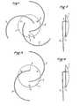
- Figs. 1 and 2in the convex plane lens 1, are fixed 3 handles 3 whose shape is semicircular. This fixing is obtained by penetration, for each of the handles, of a tenon 4 driven in a direction perpendicular to the flat face in said face.
- the length of the pins 4is such that the corresponding handle 3 protrudes above of the planar face, the plane of the branch 3 forming with the tenon 4 an angle a few degrees lower than the right angle. It is indeed essential that the handles are slightly folded relative to the plane of the lens to allow proper positioning of the implant in the anterior chamber.
- the post 4itself projects above the flat face of the lens, the length of this projection allowing the post to pass through the pupil of the eye so that the optical part of the implant is in posterior chamber while the haptics are in the interior chamber.
- the lens 1can have a diameter of 6 mm.
- the handles 3having a diameter of 0.17 mm.
- the overall dimensionsare 13.5 mm, the radius of curvature of the handles being 4.15 mm.
- the lens 1possibly has positioning holes 2.
- the pins 4are spaced 2.5 mm apart.
- the distance from the loop 3 to above the flat surface 5 of the lensis 0.8 mm. while it is only 0.5 mm at the other end of the handle.
- Figs 3 and 4are identical to Figs 1 and 2, except that the number of handles 3 is two instead of three.
- the number of handlescan be arbitrary without departing from the scope of the invention.
- the shape of the handlesis not necessarily semicircular.
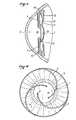
- Figs 5 and 6show an implant in position inside an eye.
- Fig.5is a section through a vertical plane while Fig.6 is a front view.
- Fig. 5there is a transparent cornea 6, the anterior chamber 7, the pupil 10 in the middle of the iris 9, the posterior chamber 8, as well as in dotted lines the posterior capsule 11 joined to the extension of the ciliary body 12 by zonular fibers 13.
- the handles 3are supported in the iridocorneal angle 15, after crossing the pupil 10.
- the pupilcan contract or expand freely.
- the wearerdoes not see the handles which, moreover, are transparent.
- Fig.6shows the arrangement of the handles 3 which, in the example shown are three in number, above the iris 9, the pins 4 passing through the pupil 10. As shown in Fig, handles 3 come to rest in the angle 15 in a tangential manner, this arrangement making it possible to benefit from all the elastic reaction qualities of the handles 3.
Landscapes
- Health & Medical Sciences (AREA)
- Ophthalmology & Optometry (AREA)
- Life Sciences & Earth Sciences (AREA)
- Engineering & Computer Science (AREA)
- Biomedical Technology (AREA)
- Heart & Thoracic Surgery (AREA)
- Vascular Medicine (AREA)
- Animal Behavior & Ethology (AREA)
- General Health & Medical Sciences (AREA)
- Public Health (AREA)
- Veterinary Medicine (AREA)
- Oral & Maxillofacial Surgery (AREA)
- Transplantation (AREA)
- Cardiology (AREA)
- Prostheses (AREA)
Abstract
Description
Translated fromFrenchLa présente invention a pour objet un cristallin artificiel ou implant intraoculaire destiné en particulier, mais non exclusivement,à être mis en place après une opération de la cataracte. Le but de cette prothèse est d'éviter à l'opéré le port permanent de lunettes très épaisses destinées à pallier l'absence du cristallin naturel.The present invention relates to an artificial lens or intraocular implant intended in particular, but not exclusively, to be placed after a cataract operation. The purpose of this prosthesis is to avoid the patient having to wear permanent, very thick glasses intended to compensate for the absence of the natural lens.
Le cristallin naturel chez l'homme est une structure transparente dont le diamètre est de l'ordre de 9mm pour une épaisseur de 5 mm. environ, de forme générale lenticulaire, suspendœ derrière l'iris par des fibres zonulaires qui relient le cristallin au corps ciliaire. La cataracte consiste en une opacification de l'une,ou des capsules,antérieure ou postérieure qui constituent le sac cristallin. L'opération de la cataracte consiste en l'ablation du cristallin et est désignée comme "intracapsulaire" lorsque la capsule est retirée en même temps que le cristallin et, comme "extracapsulaire" lorsque la capsule antérieure est extraite avec le cristallin alors que la capsule postérieure est laissée à l'intérieur de l'oeil.The natural lens in humans is a transparent structure whose diameter is around 9mm for a thickness of 5mm. approximately, generally lenticular, suspended behind the iris by zonular fibers which connect the lens to the ciliary body. The cataract consists of an opacification of one, or capsules, anterior or posterior which constitute the crystalline bag. The cataract operation consists of the removal of the lens and is designated as "intracapsular" when the capsule is removed at the same time as the lens and, as "extracapsular" when the anterior capsule is extracted with the lens while the capsule posterior is left inside the eye.
La première lentille intraoculaire a été implantée par RIDLEY en 1949 et, depuis cette date différents types de cristallins artificiels ont été proposés. On peut citer, notamment les brevets US-A- 3 991 426 et US-A- 4 092 743.The first intraocular lens was implanted by RIDLEY in 1949 and, since that date, different types of artificial lenses have been proposed. Mention may be made, in particular of US-A-3,991,426 and US-A-4,092,743.
Parmi les problèmes que posent l'implantation et le port de lentilles intraoculaires celui de la fixation de l'implant à l'intérieur de la cavité oculaire est l'un des plus critiques. Pour des raisons de tolérance, les lentilles, qui étaient à l'origine disposées dans le plan iridien, sont maintenant implantées soit dans la chambre antérieure constituée par la cornée et l'iris, soit dans la chambre postérieure constituée par l'iris et la membrane hyaloïde de l'humeur vitrée. Les implants sont maintenus par des anses souples prenant appui, dans le cas d'un implant de chambre antérieure, dans l'angle irido-cornéen ou angle de l'oeil et, dans le cas d'un implant de chambre postérieure, dans le sulcus ou corps ciliaire. L'optique est habituellement contituée par une lentille de forme générale plan-convexe en matière synthétique tolérée par l'organisme à partir de laquelle s'étendent, dans une direction sensiblement radiale les haptiques. Celles-ci sont généralement constituées par des anses souples du type "Sinskey" ou "J-loop", dont le matériau peut être le même que celui de la lentille qui, habituellement,présente une convergence de 19 à 21 dioptries.Among the problems posed by implantation and the wearing of intraocular lenses, that of the fixation of the implant inside the ocular cavity is one of the most critical. For reasons of tolerance, the lenses, which were originally arranged in the iridian plane, are now implanted either in the anterior chamber formed by the cornea and the iris, or in the posterior chamber formed by the iris and the vitreous humor hyaloid membrane. The implants are held in place by flexible handles which are supported, in the case of an anterior chamber implant, in the iridocorneal angle or angle of the eye and, in the case of a posterior chamber implant, in the sulcus or ciliary body. The optics are usually formed by a generally plano-convex plastic lens tolerated by the organism from which the haptics extend in a substantially radial direction. These are generally formed by flexible handles of the "Sinskey" or "J-loop" type, the material of which can be the same as that of the lens which, usually, has a convergence of 19 to 21 diopters.
L'un des inconvénients majeurs de ce type de fixation réside dans les risques de luxation de l'implant lors des mouvements de l'iris. Il devient dangereux de provoquer une dilatation de la pupille en vue de l'observation de la rétine. D'autre part, _les contraintes mécaniques qu'imposent les anses aux tissus au niveau des zones de contact provoquent une gêne, voire un traumatisme des tissus qu'il faut traiter par voie médicamenteuse ou opérer. La multiplication des surfaces de contact augmente le risque de formation d'adhérences alors que de faibles surfaces de contact augmentent les risques de luxation de l'implant et les captures iriennes qui consistent dans le passage d'une partie de l'iris en avant ou en arrière de l'implant. Les opérations de suture des anses sur l'iris se sont révélées extrêmement délicates et ne peuvent faire l'objet d'une grande extension.One of the major drawbacks of this type of fixation lies in the risks of dislocation of the implant during movements of the iris. It becomes dangerous to cause dilation of the pupil for observation of the retina. On the other hand, the mechanical stresses imposed by the handles on the tissues at the level of the contact zones cause discomfort, or even trauma to the tissues which must be treated by medication or operated. The multiplication of contact surfaces increases the risk of adhesion formation while small contact surfaces increase the risk of dislocation of the implant and the iris captures which consist in the passage of part of the iris in front or behind the implant. The suturing operations of the handles on the iris have proved to be extremely delicate and cannot be extended.
La présente invention a pour objet de pallier les défauts des implants connus et de faciliter la mise en place et, après opération, le maintien de l'implant.The object of the present invention is to remedy the defects of known implants and to facilitate the positioning and, after operation, the maintenance of the implant.
Selon la présente invention, le cristallin artificiel du type comprenant une optique et des anses souples, l'optique étant implantée dans la chambre postérieure, est caractérisé en ce qu'il comprend au moins deux anses fixées dans la face plane de la lentille plan-convexe, dont la face convexe est tournée vers l'arrière, les anses faisant saillie à partir de la face plane et formant avec celle-ci un angle de l'ordre de 5°, lesdites anses prenant appui, après mise en place, dans l'angle irido-cornéen après traversée de la pupille. Ainsi, l'implant est parfaitement suspendu dans la chambre antérieure alors que l'optique se trouve en chambre postérieure. Tout risque de luxation ou de capture irienne se trouve ainsi supprimé.According to the present invention, the artificial lens of the type comprising an optic and flexible handles, the optic being located in the posterior chamber, is characterized in that it comprises at least two handles fixed in the flat face of the planar lens. convex, the convex face of which is turned towards the rear, the handles protruding from the flat face and forming an angle of about 5 ° therewith, said handles being supported, after installation, in the iridocorneal angle after crossing the pupil. Thus, the implant is perfectly suspended in the anterior chamber while the optic is in the posterior chamber. Any risk of dislocation or iris capture is thus eliminated.
De préférence, les anses sont au nombre de trois et leur forme est semicirculaire. Cette disposition permet un auto- centrage de l'implant et assure une bonne stabilité au montage. Par ailleurs, la convexité postérieure de la lentille permet de tendre la capsule postérieure en cas d'ablation extracapsulaire ce qui permet d'éviter dans une large mesure une opacification ultérieure de celle-ci. Toutefois, l' implant selon l'invention peut également être utilisé après une opération intracapsulaire, la convexité postérieure servant dans ce cas à refouler l'hyaloîde du vitré vers l'arrière.Preferably, the handles are three in number and their shape is semi-circular. This arrangement allows self-centering of the implant and ensures good mounting stability. Furthermore, the posterior convexity of the lens makes it possible to tighten the posterior capsule in the event of extracapsular ablation, which makes it possible to avoid to a large extent subsequent opacification of the latter. However, the implant according to the invention can also be used after an intracapsular operation, the posterior convexity serving in this case to push the hyaloid from the vitreous backwards.
Selon une autre caractéristique de l'invention, la lentille et les anses sont réalisées en polyméthylmétacrylate (PMMA) qui s'est révélé être un matériau convenablement inerte.According to another characteristic of the invention, the lens and the handles are made of polymethylmethacrylate (PMMA) which has been found to be a suitably inert material.
D'autres caractéristiques et avantages de l'invention apparaîtront au cours de la description qui va suivre de modes particuliers de réalisation de l'invention, donnés uniquement à titre d'exemples non limitatifs, en regard des dessins qui représentent :
- - Les Figs. 1 et 2, respectivement en vue de face et en vue de profil un implant selon l'invention à trois anses;
- - Les Figs. 3 et 4, un implant à deux anses;
- - La Fig.5, une vue en coupe d'un oeil dans lequel est monté un cristallin artificiel;
- - La Fig.6, une vue de face du même oeil.
- - Figs. 1 and 2, respectively in front view and in profile view, an implant according to the invention with three handles;
- - Figs. 3 and 4, an implant with two handles;
- - Fig.5, a sectional view of an eye in which is mounted an artificial lens;
- - Fig.6, a front view of the same eye.
Sur les Figs. 1 et 2, dans la lentille plan convexe 1, sont fixées 3 anses 3 dont la forme est semicirculaire. Cette fixation est obtenue par pénétration, pour chacune des anses, d'un tenon 4 enfoncé dans une direction perpendiculaire à la face plane dans ladite face. La longueur des tenons 4 est telle que l'anse 3 correspondante fasse saillie au-dessus de de la face plane,le plan de la branche 3 formant avec le tenon 4 un angle inférieur de quelques degré à l'angle droit. Il est en effet essentiel que les anses soient légèrement rabattues par rapport au plan de la lentille pour permettre un bon positionnement de l'implant dans la chambre antérieure.In Figs. 1 and 2, in the convex plane lens 1, are fixed 3
Le tenon 4 fait lui-même saillie au-dessus de la face plane de la lentille, la longueur de cette saillie permettant au tenon de passer à travers la pupille de l'oeil de sorte que la partie optique de l'implant se trouve en chambre postérieure alors que les haptiques sont en chambre intérieure.The
A titre d'exemple, la lentille 1 peut avoir un diamètre de 6 mm., les anses 3 ayant un diamètre de 0,17 mm. L'encombrement hors-tout est de 13,5 mm, le rayon de courbure des anses étant de 4,15 mm. Comme connnu en soi, la lentille 1 présente éventuellement des trous de positionnement 2.For example, the lens 1 can have a diameter of 6 mm., The
Afin de permettre, d'une part un fonctionnement normal de l'iris et, d'autre part une vision normale du porteur de l'implant, les tenons 4 sont espacés de 2,5 mm.La distance de l'anse 3 au-dessus de la surface plane 5 de la lentille est de 0,8 mm. alors qu'elle n'est plus que de 0,5 mm à l'autre extrémité de l'anse.In order to allow, on the one hand a normal functioning of the iris and, on the other hand a normal vision of the wearer of the implant, the
Les Figs 3 et 4 sont identiques aux Figs 1 et 2, à ceci près que le nombre d'anses 3 est de deux au lieu de trois. Le nombre d'anses peut être quelconque sans sortir pour celà du cadre de l'invention.De.même, la forme des anses n'est pas nécessairement semicirculaire.Figs 3 and 4 are identical to Figs 1 and 2, except that the number of
Les Figs 5 et 6 représentent un implant en position à l'intérieur d'un oeil. La Fig.5 est une coupe par un plan vertical alors que la Fig.6 est une vue de face.Figs 5 and 6 show an implant in position inside an eye. Fig.5 is a section through a vertical plane while Fig.6 is a front view.
Sur la Fig.5, on distingue la cornée transparente 6, la chambre antérieure 7, la pupille 10 au milieu de l'iris 9, la chambre postérieure 8, ainsi qu'en traits pointillés la capsule postérieure 11 réunie à l'extension du corps ciliaire 12 par des fibres zonulaires 13. Alors que dans la technique antérieure les anses des implants de chambre postérieure prenaient appui contre le corps ciliaire 14, conformément à l'invention, les anses 3 prennent appui dans l'angle irido-cornéen 15, après traversée de la pupille 10. Etant donné la position des tenons 4, la pupille peut se contracter ou se dilater librement. D'autre part, en raison de la focalisation introduite par la lentille, le porteur ne voit pas les anses qui, de plus sont transparentes.In Fig. 5, there is a
La Fig.6 montre la disposition des anses 3 qui, dans l'exemple représenté sont au nombre de trois, au-dessus de l'iris 9, les tenons 4 passant à travers la pupille 10. Comme celà apparaît sur la Fig, les anses 3 viennent reposer dans l'angle 15 d'une manière tangentielle, cette disposition permettant de bénéficier de toutes les qualités élastiques de réaction des anses 3.Fig.6 shows the arrangement of the
Il va de soi que de nombreuses variantes peuvent être apportées, notamment par substitution de moyens techniquement équivalents, sans sortir pour celà du cadre de la présente invention tel qu'il est défini par les revendications annexées.It goes without saying that many variants can be made, in particular by substitution of technically equivalent means, without departing from the scope of the present invention as defined by the appended claims.
Claims (4)
Translated fromFrenchPriority Applications (1)
| Application Number | Priority Date | Filing Date | Title |
|---|---|---|---|
| EP83402300AEP0154655A1 (en) | 1983-11-30 | 1983-11-30 | Artificial crystalline lens |
Applications Claiming Priority (1)
| Application Number | Priority Date | Filing Date | Title |
|---|---|---|---|
| EP83402300AEP0154655A1 (en) | 1983-11-30 | 1983-11-30 | Artificial crystalline lens |
Publications (1)
| Publication Number | Publication Date |
|---|---|
| EP0154655A1true EP0154655A1 (en) | 1985-09-18 |
Family
ID=8191468
Family Applications (1)
| Application Number | Title | Priority Date | Filing Date |
|---|---|---|---|
| EP83402300AWithdrawnEP0154655A1 (en) | 1983-11-30 | 1983-11-30 | Artificial crystalline lens |
Country Status (1)
| Country | Link |
|---|---|
| EP (1) | EP0154655A1 (en) |
Cited By (1)
| Publication number | Priority date | Publication date | Assignee | Title |
|---|---|---|---|---|
| WO1999056669A1 (en)* | 1998-05-05 | 1999-11-11 | Pharmacia & Upjohn Groningen B.V. | Intraocular lens having a design for controlling its axial displacement after implantation |
Citations (5)
| Publication number | Priority date | Publication date | Assignee | Title |
|---|---|---|---|---|
| BE873297A (en)* | 1979-01-04 | 1979-05-02 | Galand Albert | ROUND PUPIL IRIEN IMPLANT |
| US4257130A (en)* | 1979-08-27 | 1981-03-24 | Bayers Jon Herbert | Intraocular lens mechanism |
| EP0053384A1 (en)* | 1980-12-01 | 1982-06-09 | Gerald D. Faulkner | Posterior chamber intraocular lens |
| US4340979A (en)* | 1981-03-18 | 1982-07-27 | Kelman Charles D | Intraocular lens |
| EP0067765A1 (en)* | 1981-06-16 | 1982-12-22 | Khalil Hanna | Intraocular implant |
- 1983
- 1983-11-30EPEP83402300Apatent/EP0154655A1/ennot_activeWithdrawn
Patent Citations (5)
| Publication number | Priority date | Publication date | Assignee | Title |
|---|---|---|---|---|
| BE873297A (en)* | 1979-01-04 | 1979-05-02 | Galand Albert | ROUND PUPIL IRIEN IMPLANT |
| US4257130A (en)* | 1979-08-27 | 1981-03-24 | Bayers Jon Herbert | Intraocular lens mechanism |
| EP0053384A1 (en)* | 1980-12-01 | 1982-06-09 | Gerald D. Faulkner | Posterior chamber intraocular lens |
| US4340979A (en)* | 1981-03-18 | 1982-07-27 | Kelman Charles D | Intraocular lens |
| EP0067765A1 (en)* | 1981-06-16 | 1982-12-22 | Khalil Hanna | Intraocular implant |
Cited By (3)
| Publication number | Priority date | Publication date | Assignee | Title |
|---|---|---|---|---|
| WO1999056669A1 (en)* | 1998-05-05 | 1999-11-11 | Pharmacia & Upjohn Groningen B.V. | Intraocular lens having a design for controlling its axial displacement after implantation |
| AU754924B2 (en)* | 1998-05-05 | 2002-11-28 | Amo Groningen B.V. | Intraocular lens having a design for controlling its axial displacement after implantation |
| US6533814B1 (en) | 1998-05-05 | 2003-03-18 | Pharmacia Groningen, Bv | Intraocular lens having a design for controlling its axial displacement after implantation |
Similar Documents
| Publication | Publication Date | Title |
|---|---|---|
| EP0128784B1 (en) | Posterior chamber ocular implant | |
| US5876442A (en) | Intraocular lens implant with telescope support | |
| US5814103A (en) | Intraocular lens and telescope with mating fasteners | |
| JP4198059B2 (en) | Intraocular lens | |
| US6926736B2 (en) | Accommodative intraocular lens | |
| CA2379287C (en) | Implant forming multifocal intraocular lens | |
| US6007579A (en) | Intraocular carrying member with attachment for telescope | |
| FR2465473A1 (en) | ARTIFICIAL CRYSTALLINE AND METHOD OF IMPLANTING THE SAME | |
| FR2681524A1 (en) | CRYSTALLINE IMPLANT. | |
| FR2530457A1 (en) | IMPROVED FIXING SYSTEM FOR INTRA-OCULAR LENS STRUCTURES | |
| US20050015144A1 (en) | Intraocular lens system | |
| US20090198326A1 (en) | Accommodative intraocular lens system | |
| EP0935448B1 (en) | Intraocular implant with flexible optical part and single circular loop | |
| FR2584919A1 (en) | YAG-compatible posterior chamber intraoccular implant | |
| EP1092402B1 (en) | Prismatic intraocular lens for the posterior chamber of the eye | |
| EP1112045B1 (en) | Intraocular implant for anterior chamber | |
| JP2006500181A (en) | Intraocular lens | |
| FR2661816A1 (en) | Artificial crystalline lens comprising means promoting implantation in order to ensure imperviousness and prevent the migration of the aqueous humor towards the rear | |
| EP0276331A1 (en) | Intraocular implant for correcting aphakia | |
| EP0154655A1 (en) | Artificial crystalline lens | |
| FR2507469A1 (en) | INTRAOCULAR IMPLANT | |
| FR2797177A1 (en) | PRECRYSTALLINE INTRAOCULAR IMPLANT | |
| BE1016898A3 (en) | Posterior chamber intraocular implant for capsular bag of patient`s eye, has cylindrical optical part with optical axis, and tabs with outer cylinder having cylindrical axis, where optical axis and cylindrical axis are not coaxial | |
| JP2559133B2 (en) | Posterior chamber intraocular lens | |
| WO2025124898A1 (en) | Intraocular implant |
Legal Events
| Date | Code | Title | Description |
|---|---|---|---|
| PUAI | Public reference made under article 153(3) epc to a published international application that has entered the european phase | Free format text:ORIGINAL CODE: 0009012 | |
| AK | Designated contracting states | Designated state(s):CH DE GB LI NL SE | |
| 17P | Request for examination filed | Effective date:19860313 | |
| 17Q | First examination report despatched | Effective date:19870327 | |
| STAA | Information on the status of an ep patent application or granted ep patent | Free format text:STATUS: THE APPLICATION IS DEEMED TO BE WITHDRAWN | |
| 18D | Application deemed to be withdrawn | Effective date:19870807 |