EP0148783B1 - Mail sorting system with coding devices - Google Patents
Mail sorting system with coding devicesDownload PDFInfo
- Publication number
- EP0148783B1 EP0148783B1EP85300150AEP85300150AEP0148783B1EP 0148783 B1EP0148783 B1EP 0148783B1EP 85300150 AEP85300150 AEP 85300150AEP 85300150 AEP85300150 AEP 85300150AEP 0148783 B1EP0148783 B1EP 0148783B1
- Authority
- EP
- European Patent Office
- Prior art keywords
- data
- sorting
- coding devices
- sorters
- Prior art date
- Legal status (The legal status is an assumption and is not a legal conclusion. Google has not performed a legal analysis and makes no representation as to the accuracy of the status listed.)
- Expired
Links
Images


Classifications
- B—PERFORMING OPERATIONS; TRANSPORTING
- B07—SEPARATING SOLIDS FROM SOLIDS; SORTING
- B07C—POSTAL SORTING; SORTING INDIVIDUAL ARTICLES, OR BULK MATERIAL FIT TO BE SORTED PIECE-MEAL, e.g. BY PICKING
- B07C3/00—Sorting according to destination
- B07C3/02—Apparatus characterised by the means used for distribution
- B07C3/06—Linear sorting machines in which articles are removed from a stream at selected points
- B—PERFORMING OPERATIONS; TRANSPORTING
- B07—SEPARATING SOLIDS FROM SOLIDS; SORTING
- B07C—POSTAL SORTING; SORTING INDIVIDUAL ARTICLES, OR BULK MATERIAL FIT TO BE SORTED PIECE-MEAL, e.g. BY PICKING
- B07C3/00—Sorting according to destination
- B07C3/20—Arrangements for facilitating the visual reading of addresses, e.g. display arrangements coding stations
- G—PHYSICS
- G06—COMPUTING OR CALCULATING; COUNTING
- G06K—GRAPHICAL DATA READING; PRESENTATION OF DATA; RECORD CARRIERS; HANDLING RECORD CARRIERS
- G06K5/00—Methods or arrangements for verifying the correctness of markings on a record carrier; Column detection devices
- G—PHYSICS
- G06—COMPUTING OR CALCULATING; COUNTING
- G06V—IMAGE OR VIDEO RECOGNITION OR UNDERSTANDING
- G06V10/00—Arrangements for image or video recognition or understanding
- G06V10/98—Detection or correction of errors, e.g. by rescanning the pattern or by human intervention; Evaluation of the quality of the acquired patterns
- G06V10/987—Detection or correction of errors, e.g. by rescanning the pattern or by human intervention; Evaluation of the quality of the acquired patterns with the intervention of an operator
- Y—GENERAL TAGGING OF NEW TECHNOLOGICAL DEVELOPMENTS; GENERAL TAGGING OF CROSS-SECTIONAL TECHNOLOGIES SPANNING OVER SEVERAL SECTIONS OF THE IPC; TECHNICAL SUBJECTS COVERED BY FORMER USPC CROSS-REFERENCE ART COLLECTIONS [XRACs] AND DIGESTS
- Y10—TECHNICAL SUBJECTS COVERED BY FORMER USPC
- Y10S—TECHNICAL SUBJECTS COVERED BY FORMER USPC CROSS-REFERENCE ART COLLECTIONS [XRACs] AND DIGESTS
- Y10S209/00—Classifying, separating, and assorting solids
- Y10S209/90—Sorting flat-type mail
Definitions
- This inventionrelates to a mail sorting system, more particularly, a mail sorting system provided with a plurality of mail sorters and coding devices.
- This mail sorterincludes a reading device for obtaining a postal code image or an address printed on postal matter such as letters, cards or periodical mail, a recognition unit for determining the destination of the postal matter upon recognition of the image and a sorting device for delivering the postal matter to stacking bins on sorting shelves in accordance with the destination determined by the recognition unit.
- Another type of known mail handling deviceuses coding equipment as described, for example, in British Patent Application No. GB 2 066 018.
- This coding equipmentincludes the reading device described above for obtaining images of the postal matter but does not include a recognition unit. Instead, one or more cobing stations or coding devices are provided which comprise a monitor and keyboard. Successive images are displayed on the monitor so that the operator, upon watching the monitor, can input the proper postal code or area code on the keyboard.
- the described coding equipmentis more reliable than the formerly described sorting device because available recognition units cannot yet get - a recognition rate of 100%.
- recognition unitscannot recognise the postal code, the mail is rejected and delivered to a special stacking bin, which must be manually sorted at a later time.
- the disadvantage of coding equipmentis that it requires more labor and can sometimes attain less performance than sorting devices with recognition units.
- the present inventionseeks to provide a mail sorting system with improved sorting efficiency and which requires less- labor.
- the inventionalso seeks to provide a mail sorting system with coding devices which are capable of sorting a large amount of mail irrespec- . tive of variations in the amount of rejected or unrecognized mail over time.
- a mail sorting systemwhich includes a plurality of mail sorters and a plurality of coding devices.
- Each mail sorterincludes a recognition unit which occasionally fails to recognize postal code or address information.
- Each coding deviceincludes a display device and a keyboard.
- a distributorwhich has a plurality of file units corresponding to the mail sorters, is connected between mail sorters and coding devices.
- the distributoris further provided with an assigning controller and a memory which stores control tables.
- the control tablescontain supervising information about the mail sorters and coding devices such as the frequency and number of rejections by each recognition unit and the processing condition of the coding devices.
- the assigning controlleridentifies a coding device where the rejected image in the file unit should be transferred using the control tables.
- the distributorthen transfers the rejected image to a selected coding device.
- the coding devicedisplays the rejected image on the display device so that the operator can enter corrected data, such as the correct postal code or address, on the keyboard.
- the distributorsupplies the corrected data .to a main sorter so that mail rejected by a particular recognition unit can be automatically delivered to a sorting device.
- FIG. 1shows a block diagram of the mail sorting system of the preferred embodiment of the present invention.
- the mail sorting systemincludes a plurality of mail sorters 1a, 1b,..., 1n n and a plurality of coding devices 3a, 3b, ..., 3m.
- Distributor 2is provided for transferring data between mail sorters 1 and coding devices 3.
- Assigning controller 4, which is connected to distributor 2,enables distributor 2 to select the appropriate control device to which data should be transferred using tables stored in memory 5.
- Each mail sorterincludes reading device or section 11 which scans postal mail to read the postal code or address printed or handwritten on the mail.
- Reading section 11is a conventional reading device except for waiting path 115, which is described in further detail below.
- Recognition unit 12is a conventional recognition unit that recognizes each number or character forming the postal code from the image data obtained by reading section 11.
- Sorting device or section 13is a conventional sorting device that has a plurality of stacking bins (not shown) corresponding to destinations defined by postal code.
- Sort control unit 14controls gates (not shown) provided in each stacking bin to deliver the mail to the designated stacking bin in accordance with the postal code recognised by the recognition unit.
- the postal codeindicates not only wide area codes but also more detailed area codes such as the city, town, ward, etc.
- FIG. 2is a perspective view of one of the mail sorters.
- Stacks of postal mattersuch as cards and letters are placed vertically in feeding device 111 and sequentially fed one at a time by feeder 112.
- Each piece of mail Ais conveyed along conveyance path 113, which can include a conveyance belt, to conventional reading unit 114.
- Reading unit 114includes an optical scanning system (not shown), such as CCD sensor device, which obtains image data of mail A. The image data is supplied to recognition unit 12.
- Recognition unit 12recognizes each character or number of the postal code from the image data supplied by reading unit 114, and then outputs certain recognition data to sort control unit 14 in the format shown in Figure 3A which includes a designation code, reading time (RT) and mail serial number (MSN), the latter two of which are determined by reading unit 114. For many reasons, such as noise, smudges or stains on the mail, etc., no known recognition unit can recognize postal codes or mail at a rate of 100%, although the rate of rejection is less than several percent. Therefore, according to the preferred embodiment, recognition unit 12 supplies rejected data to distributor 2 in the format shown in Figure 3B when mail is rejected by the recognition unit. The rejected data includes not only reading time (RT) and mail serial number (MSN), but also unrecognized image data. At the same time rejected data is supplied to distributor 2, recognition unit 12 supplies recognition data to sorting control unit 14 wherein the recognition data contains a destination code which is a specific code indicating that the destination is uncertain.
- RTreading time
- MSNmail serial number
- distributor 2Upon receiving the rejected data, distributor 2 selects one of coding devices 3a, 3b, ..., 3n, which are conventional coding devices each having a CRT display (not shown) for displaying the rejected image and a keyboard (not shown) for inputting the correct zip code. Distributor 2 generates transfer data in the format shown in Figure 3C. When the operator watches the rejected image on the CRT display and inputs the correct zip code, the coding device generates corrected data in the format shown in Figure 3D, including the correct zip code as the input code, and supplies the corrected data to distributor 2. Distributor 2 transfers the corrected data to sorting control unit 14.
- FIG. 4is a block diagram showing an example of sorting control unit 14 of Figure 1.
- Unit 14includes random access memory 141 storing waiting table WT, read only memory 142 storing gate table GT, counter 143 and control circuit 144.
- the waiting table WTis formed of a plurality of recognition data successively supplied by recognition unit 12.
- Gate table GTindicates the relation between the zip code and the corresponding gate number assigned to each gate of the stacking bin.
- the content of counter 143is the earliest mail serial number EMSN indicating the earliest mail to arrive at sorting section 13.
- FIG. 5is a flow chart showing the operation of control circuit 144 in Figure 4.
- control circuit 144reads the waiting table WT in random access memory 142 to obtain recognition data corresponding to the earliest mail.
- Step S10is carried out by first obtaining the EMSN from counter 143 and searching the recognition data in memory 161 for a mail serial number MSN coinciding with the EMSN. Since it takes several seconds for mail to pass through waiting path 115 as noted above, the read time RT of the earliest recognition data is compared with present time at step S11.
- control circuit 144instructs the gates of sorting section 13 by first reading the gate number from gate table GT in ROM 142, supplying the destination code of the earliest mail recognition data and then supplying the gate number to sorting section 13. Sorting section 13, upon receiving the gate number, opens the corresponding gate to deliver the earliest mail to the designated stacking bin.
- control circuit 144accesses memory 141 to erase the earliest recognition data from waiting table WT, enables counter 143 to count up by 1 for the next mail and returns to step S10.
- control circuit 144checks whether recognition data has been supplied. When recognition data is supplied from recognition unit 12, control circuit 144 writes this data into the waiting table WT at step S15 and returns to step S10. When recognition data is supplied from recognition unit 12, control circuit 144 writes this data into the waiting table WT at step S15 and returns to step S10. When recognition data is not supplied, at step S16, control circuit 144 checks whether corrected data has been supplied from distributor 2. If recognition data has been supplied, control circuit 144 searches for recognition data whose MSN coincides with the corrected data, and writes the input code of the corrected data as a destination code of the coincident recognition data. Thus, the rejected code is replaced by a corrected zip code input by an operator at one of the coding devices. If corrected data is not supplied, control circuit 144 returns to step S10.
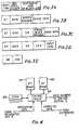
- FIG 6is a block diagram showing an example of distributor 2 in Figure 1.
- Receivers 21a,... 21n, file units 22a,... 22nare transmitters 23a, ... 23n correspond to sorters 1 a, ... 1 n.
- Each file unit 22is a memory for temporarily storing rejected data supplied by the recognition unit of the corresponding mail sorter until assigning controller 4 determines the coding device to which rejected data should be transmitted.
- Distributor 2further includes switching circuits 24, 25 and control circuit 26, the operation of which will be described below in connection with the flow charts for distributor 2 and assigning controller 4.
- Figure 7is a flow chart showing the operation of distributor 2.
- control circuit 26determines whether instruction data has been supplied by assigning controller 4.
- Instruction dataincludes sorter number SN and coding device number CDN as shown in Figure 3E.
- control circuit 26supplies a read signal to the file unit and the instruction data to the transmitter corresponding to the SN of the instruction data.
- SN and CDN of the instruction dataidentify sorter 1a and coding device 3b
- the read signalis supplied to file unit 22a and a transmit signal is supplied to transmitter 23a.
- File unit 22aoutputs rejected data having the smallest MSN or whose RT to transmitter 23a.
- Transmitter 23athen generates transfer data consisting of the combination of the rejected data and the instruction data as shown in Figure 3C.
- control circuit 26supplies the instruction data to switching circuit 24 which connects transmitter 23a and coding device 3b.
- the transfer data output by transmitter 23ais supplied to coding device 3b.
- control circuit 26supplies a delete signal to file unit 22a.
- File unit 22adeletes the rejected data just sent to coding device 3b.
- Steps S24 and S25concern the control tables stored in memory 5 in the manner shown in Figure 8.
- two control tables T1 and T2are provided.
- T1(1), T1 (2), ..., T1 (N) of control table T1correspond to the file units in the distributor where N is the number of mail sorters.
- T2(1 ), T2(2), . . ., T2(M) of control table T2indicate the number of blocks of transfer data received but not processed by the coding devices where M is the number of coding devices.
- control circuit 26counts down T1 (n) by 1, where n is the corresponding sorter number SN of the instruction data.
- control circuit 26counts up T2(m) by 1, where m is the corresponding coding device number CDN of the instruction data. The control circuit then returns to step S20.
- control circuit 26determines whether corrected data has been supplied by one of the coding devices at step S26.
- the corrected data supplied by one of the coding deviceswhich includes replacing an input code with correct zip code, replaces the image data in the transfer data. If control circuit 26 receives a control signal from switching circuit 25, indicating that the corrected data has been supplied by a coding device, at step S27, the control circuit returns a send signal to switching circuit 25 to send the corrected data to the mail sorter designated by the SN of the corrected data.
- control circuit 26receives the CND of the corrected data from switching circuit 25 and counts down the T2(m) of control table T2 designated by the CDN. Then control returns to step S20.
- control circuit 26determines whether rejected data has been supplied by one of the mail sorters at step S29.
- step S30when one of the receivers receives rejected data, it generates a receive signal which enables control circuit 26 to generate and send a write signal to the corresponding file unit to enable the file unit to write the rejected data.
- Control circuit 26then counts up T1(n) of control table T1 at step S31 where n identifies the receiver which generated the receive signal.
- distributor 2controls data transfer between the mail sorters and coding devices and also updates the control tables in response to each data transfer.
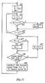
- FIG 9is a flow chart showing the operation of assigning controller 4 in Figure 1.
- assigning controller 4is a conventional microcomputer such as a microcontroller chip having internal registers (not shown), one of which is assigned as an SN counter whose content indicates a sorter number SN and another of which is assigned as a CDN counter whose content indicates a coding device number CDN.
- Steps S40 through S43form a routine for searching for a file unit whose rejected data should be sent to one of the coding devices.
- the content n of the SN counteris compared with N, i.e., the number of mail sorters.
- assigning controller 4executes another routine formed by steps S44 through S47 to determine which of the coding devices is available to process the rejected data.
- the content m of the CDN counteris compared with M, i.e., the number of coding devices.
- assigning controller 4reads T2(m) of the control table T2 as designated by the content m of the CDN counter.
- T2(m)>2that is, the m-th coding device has too much unprocessed data
- the CDN counteris counted up by 1 at step S47 and the above routine is repeated.
- T2(m) ⁇ _ 2that is the m-th coding device has no unprocessed data or at most 2 items of unprocessed data
- the assigning controllerdetermines that the rejected data in the m-th file unit should be processed by the m-th coding device.
- assigning controller 4generates instruction data using the contents n, m of the SN and CDN counters and supplies this instruction data to control circuit 26 of distributor 2.
- the distribution order of file units to coding devicesis determined by checking whether untransmitted image data is stored in the file units or not.
- Figures 10 and 11show flow charts for an alternative embodiment of distributor 2 and assigning controller 4 in which the distribution order is based on read time RT.
- control table T3is provided in memory 5 for storing the earliest read time RT for each file unit.
- Figure 10is similar to Figure 7 except that step S24 is replaced by step S50 and step S31 is deleted.
- step S50the n-th element in control table T3 is updated or renewed by control circuit 26 by writing RT in this element.
- RTis the earliest time among rejected image data of the n-th file unit whose rejected data has just been transferred to a coding device at step S22. If there is no rejected data left in the n-th file unit, a predetermined time larger than any expected actual time is written as T 3 (n).
- control circuit 26always updates or renews control table T3 after sending transfer data to a coding device.
- assigning controller 4is a microcomputer such as a microcontroller chip with a plurality of internal registers.
- datais sent to internal registers (not shown) of assigning controller 4, i.e., an SN counter designates the file unit, an R register temporarily stores RT and an RN register stores the SN whose corresponding RT is the earliest in control table T3.
- step S51the SN and RN counters are set to 1 and the first element T3(1) of control table T3 is sent to the R register.
- the content of the SN counteris incremented by 1 at step S52.
- step S53the n-th element T3(n) of control table T3 is read out from memory 5 and compared with the content of the R register.
- T3(n)is smaller, i.e., earlier, than the content of the R register
- the content of the R registeris replaced by T3(n) and also the content of the RN register is replaced by the content of the SN counter.
- step S54is skipped.
- the content of the SN counteris checked at step S55. When it is less than N, steps S52 through S55 are skipped. When the content of the SN counter reaches N, the routine for searching a file unit is completed and the content of the RN register indicates the file unit whose rejected data should be sent to a coding device at that time because its reading time is the earliest among rejected data.
- Figure 12shows another embodiment of the control table for assigning coding devices.
- the control tableis a two-dimensional array in which the amount of rejected data for the n-th sorter is coded by the m-th coding device.
- This control tablecan be easily generated and updated by distributor 2. From this control table, assigning controller 4 can easily determine which mail sorter or sorters generate excessive amounts of rejected data or which coding device has very high performance and so on. Thus, for example, when the amount of rejected data from a certain mail sorter in a given period reaches a very high value, assigning controller 4 can assign a high performance coding device to this mail sorter to process excess rejected images before mail reaches sorting section 12.
Landscapes
- Engineering & Computer Science (AREA)
- Physics & Mathematics (AREA)
- General Physics & Mathematics (AREA)
- Theoretical Computer Science (AREA)
- Quality & Reliability (AREA)
- Multimedia (AREA)
- Sorting Of Articles (AREA)
- Character Input (AREA)
- Character Discrimination (AREA)
Description
- This invention relates to a mail sorting system, more particularly, a mail sorting system provided with a plurality of mail sorters and coding devices.
- Various types of automatic mail sorting devices have been proposed in order to save labor in mailing services. One known type of mail sorter is described for example, in European Patent Application EP 0 066 186. This mail sorter includes a reading device for obtaining a postal code image or an address printed on postal matter such as letters, cards or periodical mail, a recognition unit for determining the destination of the postal matter upon recognition of the image and a sorting device for delivering the postal matter to stacking bins on sorting shelves in accordance with the destination determined by the recognition unit.
- Another type of known mail handling device uses coding equipment as described, for example, in British Patent Application No.
GB 2 066 018. This coding equipment includes the reading device described above for obtaining images of the postal matter but does not include a recognition unit. Instead, one or more cobing stations or coding devices are provided which comprise a monitor and keyboard. Successive images are displayed on the monitor so that the operator, upon watching the monitor, can input the proper postal code or area code on the keyboard. - A similar system is also shown in U.S. 4,205,760 in which images of documents can also be displayed on video monitors.
- The described coding equipment is more reliable than the formerly described sorting device because available recognition units cannot yet get - a recognition rate of 100%. When recognition units cannot recognise the postal code, the mail is rejected and delivered to a special stacking bin, which must be manually sorted at a later time. However, the disadvantage of coding equipment is that it requires more labor and can sometimes attain less performance than sorting devices with recognition units.
- An improved system of this kind including a mail sorter is shown in our copending European application No. A2-0 148 87 (Art. 54(3) EPO-Document).
- In recent years, however, with the large increase in the amount of mail, mail sorting machines that can handle large quantities of mail without much labor are desired. One proposed solution has been to install several mail sorters and operate them in parallel. However, in such a parallel system, the amount of rejected mail in each mail sorter increases and different types of rejections occur in different mail sorters. Also, overtime, variations in the amount of mail handled by each sorter occur in response to the quality of postal code or address information.
- The present invention seeks to provide a mail sorting system with improved sorting efficiency and which requires less- labor.
- The invention also seeks to provide a mail sorting system with coding devices which are capable of sorting a large amount of mail irrespec- . tive of variations in the amount of rejected or unrecognized mail over time.
- According to the invention, a mail sorting system is provided which includes a plurality of mail sorters and a plurality of coding devices. Each mail sorter includes a recognition unit which occasionally fails to recognize postal code or address information. Each coding device includes a display device and a keyboard. A distributor, which has a plurality of file units corresponding to the mail sorters, is connected between mail sorters and coding devices.
- When a recognition unit in a mail sorter fails to recognise postal code or address information, the rejected image is supplied to the file unit in the distributor corresponding to the mail sorter. The distributor is further provided with an assigning controller and a memory which stores control tables. The control tables contain supervising information about the mail sorters and coding devices such as the frequency and number of rejections by each recognition unit and the processing condition of the coding devices. The assigning controller identifies a coding device where the rejected image in the file unit should be transferred using the control tables. The distributor then transfers the rejected image to a selected coding device. The coding device displays the rejected image on the display device so that the operator can enter corrected data, such as the correct postal code or address, on the keyboard. The distributor supplies the corrected data .to a main sorter so that mail rejected by a particular recognition unit can be automatically delivered to a sorting device.
- Since there is no fixed relation between mail sorters and coding devices in the mail sorting system of the present invention, this system makes it possible to deal with variations in load over time. Even when a concentration of rejected images occur in a particular mail sorter, the mail can be coded by several coding device in parallel to prevent a so-called "overflow" state. Thus, the overall sorting efficiency of the mail sorting system of the present invention is greatly improved. Furthermore, the number of coding devices can be kept to the minimum number necessaryforthe system because contrary to prior mail sorting systems, in which each sorter has one or more exclusive coding devices, there is no fixed relationship between the mail sorters and coding devices in the present mail sorting system.
- One embodiment of the invention will now be described by way of example with reference to the accompanying drawings in which:
- Figure 1 is a block diagram showing a preferred embodiment of the invention;
- Figure 2 is a perspective view showing one of mail sorters 1a to 1n in Figure 1;
- Figures 3A through 3E show data formats used in the embodiment of Figure 1;
- Figure 4 is an example of
sort control unit 14 in Figure 1; - Figure 5 is a flow chart showing the operation of
sort control unit 14 in Figure 4; - Figure 6 is a block diagram of
distributor 2 in Figure 1; - Figure 7 is a flow chart showing the operation of
distributor 2 in Figure 6; - Figure 8 is a memory map of
memory 5 in Figure 1; - Figure 9 is a flow chart showing the operation of assigning
controller 4 in Figure 1; - Figure 10 is another flow chart showing the operation of
distributor 2; - Figure 11 is another flow chart showing the operation of assigning
controller 4; and - Figure 12 is another example of a control table stored in
memory 5. - Figure 1 shows a block diagram of the mail sorting system of the preferred embodiment of the present invention. The mail sorting system includes a plurality of mail sorters 1a, 1b,..., 1n n and a plurality of
coding devices 3a, 3b, ..., 3m.Distributor 2 is provided for transferring data betweenmail sorters 1 and coding devices 3. Assigningcontroller 4, which is connected todistributor 2, enablesdistributor 2 to select the appropriate control device to which data should be transferred using tables stored inmemory 5. - Each mail sorter includes reading device or
section 11 which scans postal mail to read the postal code or address printed or handwritten on the mail. Readingsection 11 is a conventional reading device except for waitingpath 115, which is described in further detail below.Recognition unit 12 is a conventional recognition unit that recognizes each number or character forming the postal code from the image data obtained by readingsection 11. Sorting device orsection 13 is a conventional sorting device that has a plurality of stacking bins (not shown) corresponding to destinations defined by postal code. Sortcontrol unit 14 controls gates (not shown) provided in each stacking bin to deliver the mail to the designated stacking bin in accordance with the postal code recognised by the recognition unit. The postal code indicates not only wide area codes but also more detailed area codes such as the city, town, ward, etc. - Figure 2 is a perspective view of one of the mail sorters. Stacks of postal matter such as cards and letters are placed vertically in feeding
device 111 and sequentially fed one at a time byfeeder 112. Each piece of mail A is conveyed alongconveyance path 113, which can include a conveyance belt, toconventional reading unit 114. Readingunit 114 includes an optical scanning system (not shown), such as CCD sensor device, which obtains image data of mail A. The image data is supplied torecognition unit 12. After the mail passes throughreading unit 114, it enters waitingpath 115, which is a rather longer conveyance path that delays the mail for several seconds before it is conveyed to sortingsection 13. The delay is provided to make sure enough time elapses for the coding device to supply sortingcontrol unit 14 with a corrected postal code whenrecognition unit 12 cannot recognize the postal code of mail A. Recognition unit 12 recognizes each character or number of the postal code from the image data supplied by readingunit 114, and then outputs certain recognition data to sortcontrol unit 14 in the format shown in Figure 3A which includes a designation code, reading time (RT) and mail serial number (MSN), the latter two of which are determined by readingunit 114. For many reasons, such as noise, smudges or stains on the mail, etc., no known recognition unit can recognize postal codes or mail at a rate of 100%, although the rate of rejection is less than several percent. Therefore, according to the preferred embodiment,recognition unit 12 supplies rejected data todistributor 2 in the format shown in Figure 3B when mail is rejected by the recognition unit. The rejected data includes not only reading time (RT) and mail serial number (MSN), but also unrecognized image data. At the same time rejected data is supplied todistributor 2,recognition unit 12 supplies recognition data to sortingcontrol unit 14 wherein the recognition data contains a destination code which is a specific code indicating that the destination is uncertain.- Upon receiving the rejected data,
distributor 2 selects one ofcoding devices 3a, 3b, ..., 3n, which are conventional coding devices each having a CRT display (not shown) for displaying the rejected image and a keyboard (not shown) for inputting the correct zip code.Distributor 2 generates transfer data in the format shown in Figure 3C. When the operator watches the rejected image on the CRT display and inputs the correct zip code, the coding device generates corrected data in the format shown in Figure 3D, including the correct zip code as the input code, and supplies the corrected data todistributor 2.Distributor 2 transfers the corrected data to sortingcontrol unit 14. - Figure 4 is a block diagram showing an example of sorting
control unit 14 of Figure 1.Unit 14 includesrandom access memory 141 storing waiting table WT, read onlymemory 142 storing gate table GT, counter 143 andcontrol circuit 144. The waiting table WT is formed of a plurality of recognition data successively supplied byrecognition unit 12. Gate table GT indicates the relation between the zip code and the corresponding gate number assigned to each gate of the stacking bin. The content ofcounter 143 is the earliest mail serial number EMSN indicating the earliest mail to arrive at sortingsection 13. - Figure 5 is a flow chart showing the operation of
control circuit 144 in Figure 4. At step S10,control circuit 144 reads the waiting table WT inrandom access memory 142 to obtain recognition data corresponding to the earliest mail. Step S10 is carried out by first obtaining the EMSN fromcounter 143 and searching the recognition data in memory 161 for a mail serial number MSN coinciding with the EMSN. Since it takes several seconds for mail to pass through waitingpath 115 as noted above, the read time RT of the earliest recognition data is compared with present time at step S11. If the difference between the read time and the present time is beyond the time required for mail to pass through waitingpath 115 at step S12,control circuit 144 instructs the gates of sortingsection 13 by first reading the gate number from gate table GT inROM 142, supplying the destination code of the earliest mail recognition data and then supplying the gate number to sortingsection 13. Sortingsection 13, upon receiving the gate number, opens the corresponding gate to deliver the earliest mail to the designated stacking bin. The details of a typical sorting section for carrying out the above functions is disclosed for example in European Patent Application EP 0066186. Lastly, at step S13,control circuit 144 accessesmemory 141 to erase the earliest recognition data from waiting table WT, enables counter 143 to count up by 1 for the next mail and returns to step S10. - If the earliest mail has not arrived at sorting
section 13 at step S11, at step S14,control circuit 144 checks whether recognition data has been supplied. When recognition data is supplied fromrecognition unit 12,control circuit 144 writes this data into the waiting table WT at step S15 and returns to step S10. When recognition data is supplied fromrecognition unit 12,control circuit 144 writes this data into the waiting table WT at step S15 and returns to step S10. When recognition data is not supplied, at step S16,control circuit 144 checks whether corrected data has been supplied fromdistributor 2. If recognition data has been supplied,control circuit 144 searches for recognition data whose MSN coincides with the corrected data, and writes the input code of the corrected data as a destination code of the coincident recognition data. Thus, the rejected code is replaced by a corrected zip code input by an operator at one of the coding devices. If corrected data is not supplied,control circuit 144 returns to step S10. - Figure 6 is a block diagram showing an example of
distributor 2 in Figure 1.Receivers 21a,... 21n,file units 22a,... 22n aretransmitters 23a, ... 23n correspond to sorters 1 a, ... 1 n. Each file unit 22 is a memory for temporarily storing rejected data supplied by the recognition unit of the corresponding mail sorter until assigningcontroller 4 determines the coding device to which rejected data should be transmitted.Distributor 2 further includes switchingcircuits control circuit 26, the operation of which will be described below in connection with the flow charts fordistributor 2 and assigningcontroller 4. - Figure 7 is a flow chart showing the operation of
distributor 2. At step S20,control circuit 26 determines whether instruction data has been supplied by assigningcontroller 4. Instruction data includes sorter number SN and coding device number CDN as shown in Figure 3E. When the instruction data is supplied by assigningcontroller 4, at step S21,control circuit 26 supplies a read signal to the file unit and the instruction data to the transmitter corresponding to the SN of the instruction data. For example, when SN and CDN of the instruction data identify sorter 1a andcoding device 3b, the read signal is supplied to fileunit 22a and a transmit signal is supplied totransmitter 23a.File unit 22a outputs rejected data having the smallest MSN or whose RT totransmitter 23a.Transmitter 23a then generates transfer data consisting of the combination of the rejected data and the instruction data as shown in Figure 3C. At step S22,control circuit 26 supplies the instruction data to switchingcircuit 24 which connectstransmitter 23a andcoding device 3b. Thus, the transfer data output bytransmitter 23a is supplied tocoding device 3b. Thereafter, at step S23,control circuit 26 supplies a delete signal to fileunit 22a.File unit 22a deletes the rejected data just sent tocoding device 3b. - Steps S24 and S25 concern the control tables stored in
memory 5 in the manner shown in Figure 8. According to this embodiment, two control tables T1 and T2 are provided. T1(1), T1 (2), ..., T1 (N) of control table T1 correspond to the file units in the distributor where N is the number of mail sorters. T2(1 ), T2(2), . . ., T2(M) of control table T2 indicate the number of blocks of transfer data received but not processed by the coding devices where M is the number of coding devices. At step S24, as one block of the rejected data is deleted from corresponding file unit (22a),control circuit 26 counts down T1 (n) by 1, where n is the corresponding sorter number SN of the instruction data. At step S25, as the transfer data is sent to corresponding coding device (3b),control circuit 26 counts up T2(m) by 1, where m is the corresponding coding device number CDN of the instruction data. The control circuit then returns to step S20. - When instruction data has not been supplied at step S20,
control circuit 26 determines whether corrected data has been supplied by one of the coding devices at step S26. The corrected data supplied by one of the coding devices, which includes replacing an input code with correct zip code, replaces the image data in the transfer data. Ifcontrol circuit 26 receives a control signal from switchingcircuit 25, indicating that the corrected data has been supplied by a coding device, at step S27, the control circuit returns a send signal to switchingcircuit 25 to send the corrected data to the mail sorter designated by the SN of the corrected data. At step S28,control circuit 26 receives the CND of the corrected data from switchingcircuit 25 and counts down the T2(m) of control table T2 designated by the CDN. Then control returns to step S20. - When the corrected data has not been supplied at step S26,
control circuit 26 determines whether rejected data has been supplied by one of the mail sorters at step S29. At step S30, when one of the receivers receives rejected data, it generates a receive signal which enablescontrol circuit 26 to generate and send a write signal to the corresponding file unit to enable the file unit to write the rejected data.Control circuit 26 then counts up T1(n) of control table T1 at step S31 where n identifies the receiver which generated the receive signal. Thus,distributor 2 controls data transfer between the mail sorters and coding devices and also updates the control tables in response to each data transfer. - Figure 9 is a flow chart showing the operation of assigning
controller 4 in Figure 1. In the preferred embodiments, assigningcontroller 4 is a conventional microcomputer such as a microcontroller chip having internal registers (not shown), one of which is assigned as an SN counter whose content indicates a sorter number SN and another of which is assigned as a CDN counter whose content indicates a coding device number CDN. Steps S40 through S43 form a routine for searching for a file unit whose rejected data should be sent to one of the coding devices. At step S40, the content n of the SN counter is compared with N, i.e., the number of mail sorters. At step S41, if n=N, the content of the SN counter is set at 1, otherwise step S41 is skipped. At step S42, assigningcontroller 4 reads T1 (n) of control table T1 as designated by the content n of the SN counter. If T1 (n)=0, that is the n-th file unit has no rejected data, the SN counter is counter up by 1 at step 43 and the above routine is repeated. - If T1 (n)>0, that is, the n-th file unit has at least one block of rejected data, assigning
controller 4 executes another routine formed by steps S44 through S47 to determine which of the coding devices is available to process the rejected data. At step S44, the content m of the CDN counter is compared with M, i.e., the number of coding devices. At step S45, if m=M, the content of the CDN counter is set at 1, otherwise step S45 is skipped. At step S46, assigningcontroller 4 reads T2(m) of the control table T2 as designated by the content m of the CDN counter. If T2(m)>2, that is, the m-th coding device has too much unprocessed data, the CDN counter is counted up by 1 at step S47 and the above routine is repeated. If T2(m)<_2, that is the m-th coding device has no unprocessed data or at most 2 items of unprocessed data, the assigning controller determines that the rejected data in the m-th file unit should be processed by the m-th coding device. At step S48, assigningcontroller 4 generates instruction data using the contents n, m of the SN and CDN counters and supplies this instruction data to controlcircuit 26 ofdistributor 2. - According to the above embodiment of
distributor 2, in processing rejected data, the distribution order of file units to coding devices is determined by checking whether untransmitted image data is stored in the file units or not. However, it is even more efficient to distribute rejected data images in the order of read time RT, especially when a few of the mail sorters generate more rejected data than other mail sorters. Thus, Figures 10 and 11 show flow charts for an alternative embodiment ofdistributor 2 and assigningcontroller 4 in which the distribution order is based on read time RT. - In this case, control table T3 is provided in
memory 5 for storing the earliest read time RT for each file unit. Figure 10 is similar to Figure 7 except that step S24 is replaced by step S50 and step S31 is deleted. In step S50, the n-th element in control table T3 is updated or renewed bycontrol circuit 26 by writing RT in this element. In this case, RT is the earliest time among rejected image data of the n-th file unit whose rejected data has just been transferred to a coding device at step S22. If there is no rejected data left in the n-th file unit, a predetermined time larger than any expected actual time is written as T3(n). Thus,control circuit 26 always updates or renews control table T3 after sending transfer data to a coding device. - The flow chart for this second embodiment of assigning
controller 4 is shown in Figure 11. In this embodiment, as compared to the flow chart for the first embodiment shown in Figure 9, a different routine (steps SS1 through S55) for searching a file unit is employed but the same routine is employed for searching a coding device. Again; assigningcontroller 4 is a microcomputer such as a microcontroller chip with a plurality of internal registers. At first, data is sent to internal registers (not shown) of assigningcontroller 4, i.e., an SN counter designates the file unit, an R register temporarily stores RT and an RN register stores the SN whose corresponding RT is the earliest in control table T3. At step S51, the SN and RN counters are set to 1 and the first element T3(1) of control table T3 is sent to the R register. The content of the SN counter is incremented by 1 at step S52. Next, at step S53, the n-th element T3(n) of control table T3 is read out frommemory 5 and compared with the content of the R register. When T3(n) is smaller, i.e., earlier, than the content of the R register, the content of the R register is replaced by T3(n) and also the content of the RN register is replaced by the content of the SN counter. When T3(n) is larger, i.e., later in time, than the content of the R register, step S54 is skipped. The content of the SN counter is checked at step S55. When it is less than N, steps S52 through S55 are skipped. When the content of the SN counter reaches N, the routine for searching a file unit is completed and the content of the RN register indicates the file unit whose rejected data should be sent to a coding device at that time because its reading time is the earliest among rejected data. - Figure 12 shows another embodiment of the control table for assigning coding devices. In this embodiment, the control table is a two-dimensional array in which the amount of rejected data for the n-th sorter is coded by the m-th coding device. This control table can be easily generated and updated by
distributor 2. From this control table, assigningcontroller 4 can easily determine which mail sorter or sorters generate excessive amounts of rejected data or which coding device has very high performance and so on. Thus, for example, when the amount of rejected data from a certain mail sorter in a given period reaches a very high value, assigningcontroller 4 can assign a high performance coding device to this mail sorter to process excess rejected images before mail reaches sortingsection 12. - Although illustrative embodiments of this invention have been described in detail with reference to the accompanying drawings, it is to be understood that the invention is not limited to those precise embodiments. Various changes and modification to these embodiments may be made by one skilled in the art within the scope of the appended claims.
Claims (3)
Applications Claiming Priority (2)
| Application Number | Priority Date | Filing Date | Title |
|---|---|---|---|
| JP4024/84 | 1984-01-12 | ||
| JP59004024AJPS60147887A (en) | 1984-01-12 | 1984-01-12 | mail sorting device |
Publications (3)
| Publication Number | Publication Date |
|---|---|
| EP0148783A1 EP0148783A1 (en) | 1985-07-17 |
| EP0148783B1true EP0148783B1 (en) | 1989-04-05 |
| EP0148783B2 EP0148783B2 (en) | 1992-03-11 |
Family
ID=11573388
Family Applications (1)
| Application Number | Title | Priority Date | Filing Date |
|---|---|---|---|
| EP85300150AExpiredEP0148783B2 (en) | 1984-01-12 | 1985-01-09 | Mail sorting system with coding devices |
Country Status (4)
| Country | Link |
|---|---|
| US (1) | US4632252A (en) |
| EP (1) | EP0148783B2 (en) |
| JP (1) | JPS60147887A (en) |
| DE (1) | DE3569213D1 (en) |
Families Citing this family (81)
| Publication number | Priority date | Publication date | Assignee | Title |
|---|---|---|---|---|
| FR2587240B1 (en)* | 1985-09-18 | 1989-05-05 | Hotchkiss Brandt Sogeme | INSTALLATION FOR INDEXING FLAT OBJECTS, IN PARTICULAR FOR POSTAL MAIL |
| US4819176A (en)* | 1987-02-06 | 1989-04-04 | Treasure Isle, Inc. | Process control and data collection system |
| JP3038344B2 (en)* | 1987-02-24 | 2000-05-08 | 株式会社東芝 | Mail reading processor |
| USD311179S (en) | 1987-05-11 | 1990-10-09 | Bell & Howell Company | Mail sorter |
| US4985842A (en)* | 1987-11-13 | 1991-01-15 | Ward Robert L | Dynamically variable display and printer subsystem for use in sorting operations |
| US4921107A (en)* | 1988-07-01 | 1990-05-01 | Pitney Bowes Inc. | Mail sortation system |
| US5229932A (en)* | 1988-08-23 | 1993-07-20 | Pitney Bowes Inc. | Method and apparatus for categorizing and certifying mail batches |
| US4992649A (en)* | 1988-09-30 | 1991-02-12 | United States Postal Service | Remote video scanning automated sorting system |
| US5031223A (en)* | 1989-10-24 | 1991-07-09 | International Business Machines Corporation | System and method for deferred processing of OCR scanned mail |
| US5034985A (en)* | 1989-11-13 | 1991-07-23 | Pitney Bowes Inc. | Matched mailing system employing address print array recognition |
| US5042667A (en)* | 1989-11-13 | 1991-08-27 | Pitney Bowes Inc. | Sorting system for organizing in one pass randomly order route grouped mail in delivery order |
| US5009321A (en)* | 1989-11-13 | 1991-04-23 | Pitney Bowes Inc. | Sorting system for organizing randomly ordered route grouped mail in delivery order sequence |
| US5249687A (en)* | 1991-04-19 | 1993-10-05 | International Business Machines Corporation | Barcode translation for deferred optical character recognition mail processing |
| US5518122A (en)* | 1991-08-09 | 1996-05-21 | Westinghouse Electric Corp. | Modular mail processing method and control system |
| AU662922B2 (en)* | 1991-08-09 | 1995-09-21 | Westinghouse Electric Corporation | Modular mail processing method and control system |
| US5287271A (en)* | 1991-08-22 | 1994-02-15 | International Business Machines Corporation | Data processing system for optimized mail piece sorting and mapping to carrier walk sequence using real time statistical data |
| US5431288A (en)* | 1991-08-28 | 1995-07-11 | Nec Corporation | Mail sorting apparatus |
| US5387783A (en)* | 1992-04-30 | 1995-02-07 | Postalsoft, Inc. | Method and apparatus for inserting and printing barcoded zip codes |
| US5734568A (en)* | 1992-08-21 | 1998-03-31 | International Business Machines Corporation | Data processing system for merger of sorting information and redundancy information to provide contextual predictive keying for postal addresses |
| US5311597A (en)* | 1992-09-11 | 1994-05-10 | International Business Machines Corporation | Deferred optical character recognition active pigeon hole sorting of mail pieces |
| EP0589119A1 (en)* | 1992-09-25 | 1994-03-30 | International Business Machines Corporation | System and method for improving processing of OCR scanned mail |
| CA2110474C (en)* | 1992-12-03 | 1998-07-07 | Kevin D. Hunter | Mail processing system having a barcode user interface |
| DE4324255C2 (en)* | 1993-07-20 | 1998-02-05 | Siemens Ag | Method and device for sorting mail items provided with address information |
| DE69414940T2 (en)* | 1993-09-06 | 1999-04-29 | Nec Corp., Tokio/Tokyo | Method and device for sorting paper articles with means for wiping printed bar codes |
| US5850490A (en)* | 1993-12-22 | 1998-12-15 | Xerox Corporation | Analyzing an image of a document using alternative positionings of a class of segments |
| JP2977431B2 (en)* | 1993-12-27 | 1999-11-15 | 株式会社東芝 | Video coding equipment |
| DE4419430A1 (en)* | 1994-06-03 | 1995-12-07 | Licentia Gmbh | Method for controlling the input station for a letter sorting system |
| DE4428446C2 (en)* | 1994-08-11 | 1996-07-11 | Licentia Gmbh | Process for controlling the double material input of mail distribution systems |
| US5554842A (en)* | 1994-12-22 | 1996-09-10 | Pitney Bowes Inc. | Luminescent facing marks for enhanced postal indicia discrimination |
| EP0728536A1 (en)* | 1995-02-21 | 1996-08-28 | Grapha-Holding Ag | Device and method for processing mailers provided with mailing addresses |
| US6269171B1 (en)* | 1995-04-12 | 2001-07-31 | Lockheed Martin Corporation | Method for exploiting correlated mail streams using optical character recognition |
| US6363164B1 (en) | 1996-05-13 | 2002-03-26 | Cummins-Allison Corp. | Automated document processing system using full image scanning |
| US5862243A (en)* | 1996-03-06 | 1999-01-19 | Baker; Christopher A. | System for evaluating bar code quality on mail pieces |
| JPH10113618A (en)* | 1996-10-11 | 1998-05-06 | Nec Corp | Sorting information input system |
| JPH10249285A (en)* | 1997-03-12 | 1998-09-22 | Hitachi Ltd | Paper sorter |
| DE19748702C1 (en)* | 1997-11-04 | 1998-11-05 | Siemens Ag | Distributed transmission information pattern recognition method |
| US6562077B2 (en) | 1997-11-14 | 2003-05-13 | Xerox Corporation | Sorting image segments into clusters based on a distance measurement |
| US6976621B1 (en) | 1999-08-31 | 2005-12-20 | The United States Postal Service | Apparatus and methods for identifying a mailpiece using an identification code |
| US6977353B1 (en) | 1999-08-31 | 2005-12-20 | United States Postal Service | Apparatus and methods for identifying and processing mail using an identification code |
| US7081595B1 (en) | 1999-08-31 | 2006-07-25 | United States Postal Service | Apparatus and methods for processing mailpiece information in a mail processing device using sorter application software |
| US6894243B1 (en) | 1999-08-31 | 2005-05-17 | United States Postal Service | Identification coder reader and method for reading an identification code from a mailpiece |
| US7060925B1 (en) | 1999-08-31 | 2006-06-13 | United States Of America Postal Service | Apparatus and methods for processing mailpiece information by an identification code server |
| US6674038B1 (en)* | 1999-09-24 | 2004-01-06 | Siemens Dematic Postal Automation, L.P. | Information based network process for mail sorting/distribution |
| US7698147B2 (en) | 1999-09-24 | 2010-04-13 | Siemens Industry, Inc. | Information based network process for mail sorting/distribution |
| US6539098B1 (en) | 1999-09-24 | 2003-03-25 | Mailcode Inc. | Mail processing systems and methods |
| EP1153367A4 (en)* | 1999-10-15 | 2002-05-29 | Ascom Hasler Mailing Sys Inc | Technique for effectively generating postage indicia using a postal security device |
| US8701857B2 (en) | 2000-02-11 | 2014-04-22 | Cummins-Allison Corp. | System and method for processing currency bills and tickets |
| DE10010241C1 (en)* | 2000-03-02 | 2001-03-01 | Siemens Ag | Method and device for reading the addresses of consignments |
| US6394278B1 (en) | 2000-03-03 | 2002-05-28 | Sort-It, Incorporated | Wireless system and method for sorting letters, parcels and other items |
| JP3372925B2 (en)* | 2000-03-21 | 2003-02-04 | 日本電気株式会社 | Postal information input device and its data display method |
| US6405172B1 (en) | 2000-09-09 | 2002-06-11 | Mailcode Inc. | Voice-enabled directory look-up based on recognized spoken initial characters |
| US9767496B2 (en) | 2001-04-09 | 2017-09-19 | United States Postal Service | System and method for predelivery notification using mail image |
| WO2002082225A2 (en)* | 2001-04-09 | 2002-10-17 | United States Postal Service | System and method for predelivery notification using mail image |
| US8799183B2 (en) | 2001-04-09 | 2014-08-05 | United States Postal Service | System and method for predelivery notifcation using mail image |
| AU2002256132A1 (en)* | 2001-04-09 | 2002-10-21 | United States Postal Service | System, method, and article of manufacture for filtering mail items based upon recipient preference |
| US8428332B1 (en) | 2001-09-27 | 2013-04-23 | Cummins-Allison Corp. | Apparatus and system for imaging currency bills and financial documents and method for using the same |
| US6796433B2 (en) | 2001-11-07 | 2004-09-28 | Pitney Bowes Inc. | Method of post processing OCR information obtained from mailpieces using a customer specific keyword database and a mailpiece sorting apparatus |
| US6740835B2 (en) | 2001-11-28 | 2004-05-25 | Pitney Bowes Inc. | Method of outsorting return to sender mail using an incoming mail sorting apparatus |
| US6696656B2 (en) | 2001-11-28 | 2004-02-24 | Pitney Bowes Inc. | Method of processing return to sender mailpieces using voice recognition |
| US6791050B2 (en)* | 2001-12-07 | 2004-09-14 | Pitney Bowes Inc | Method and apparatus for processing and reducing the amount of return to sender mailpieces |
| DE10212085A1 (en)* | 2002-03-19 | 2003-10-09 | Siemens Ag | Method and device for reading the addresses of consignments |
| US7529716B1 (en) | 2002-06-20 | 2009-05-05 | Welsh Thomas M | Mail arbitrator |
| WO2004022253A1 (en)* | 2002-09-03 | 2004-03-18 | Siemens Aktiengesellschaft | Method and device for reading the addresses of mailings |
| US8171567B1 (en) | 2002-09-04 | 2012-05-01 | Tracer Detection Technology Corp. | Authentication method and system |
| US8627939B1 (en) | 2002-09-25 | 2014-01-14 | Cummins-Allison Corp. | Apparatus and system for imaging currency bills and financial documents and method for using the same |
| US7415131B2 (en)* | 2002-12-24 | 2008-08-19 | Siemens Energy & Automation, Inc. | Method and system for image processing |
| US7528339B2 (en) | 2003-07-31 | 2009-05-05 | Lockheed Martin Corporation | Sequencing system and method of use |
| US7723633B2 (en) | 2003-07-31 | 2010-05-25 | Lockheed Martin Corporation | Sequencing system and method of use |
| EP1836007B1 (en) | 2004-12-07 | 2015-12-02 | Lockheed Martin Corporation | Clamp for mixed mail sorter |
| US7809158B2 (en)* | 2005-05-02 | 2010-10-05 | Siemens Industry, Inc. | Method and apparatus for detecting doubles in a singulated stream of flat articles |
| US20070007328A1 (en)* | 2005-06-03 | 2007-01-11 | Cole John J | Methods and apparatus for recognizing and processing barcodes associated with mail |
| CN101296759A (en)* | 2005-10-27 | 2008-10-29 | 西门子公司 | Method and device for reading mail addresses |
| US7834289B2 (en)* | 2007-08-30 | 2010-11-16 | Bowe Bell & Howell Company | Mail processing system for address change service |
| FR2937771A1 (en)* | 2008-10-28 | 2010-04-30 | Neopost Technologies | MUTLIPEL IDENTIFIER MESSAGE PROCESSING METHOD |
| US8929640B1 (en)* | 2009-04-15 | 2015-01-06 | Cummins-Allison Corp. | Apparatus and system for imaging currency bills and financial documents and method for using the same |
| US8391583B1 (en) | 2009-04-15 | 2013-03-05 | Cummins-Allison Corp. | Apparatus and system for imaging currency bills and financial documents and method for using the same |
| US8437528B1 (en) | 2009-04-15 | 2013-05-07 | Cummins-Allison Corp. | Apparatus and system for imaging currency bills and financial documents and method for using the same |
| US8669486B2 (en)* | 2009-08-05 | 2014-03-11 | Gregory L Ward | Portable mail sorting and consolodating method and machine |
| US9044784B2 (en) | 2012-01-17 | 2015-06-02 | Lockheed Martin Corporation | Remote recognition processing system and method |
| US8625841B2 (en) | 2012-01-17 | 2014-01-07 | Lockheed Martin Corporation | Remote encoding center automation systems and methods |
| US9141876B1 (en) | 2013-02-22 | 2015-09-22 | Cummins-Allison Corp. | Apparatus and system for processing currency bills and financial documents and method for using the same |
Family Cites Families (11)
| Publication number | Priority date | Publication date | Assignee | Title |
|---|---|---|---|---|
| US3271738A (en)* | 1963-08-13 | 1966-09-06 | Ibm | Operator assisted character reading system |
| US3582884A (en)* | 1968-01-30 | 1971-06-01 | Cognitronics Corp | Multiple-scanner character reading system |
| FR2255966A1 (en)* | 1973-12-28 | 1975-07-25 | Hotchkiss Brandt Mecanisat | Postal code marking and sorting system - reads addresses on TV screen and uses keyboard to apply code marking |
| US4068212A (en)* | 1975-05-01 | 1978-01-10 | Burroughs Corporation | Method and apparatus for identifying characters printed on a document which cannot be machine read |
| JPS5942354B2 (en)* | 1976-12-17 | 1984-10-15 | 日本電気株式会社 | Delivery classification method |
| US4205780A (en)* | 1977-03-21 | 1980-06-03 | Teknekron, Inc. | Document processing system and method |
| JPS6122713Y2 (en)* | 1978-11-09 | 1986-07-08 | ||
| DE2944144A1 (en)* | 1979-11-02 | 1981-05-14 | Licentia Patent-Verwaltungs-Gmbh, 6000 Frankfurt | VIDEO CODING SYSTEM FOR LETTERS |
| JPS57190683A (en)* | 1981-05-19 | 1982-11-24 | Tokyo Shibaura Electric Co | Sorter for letter mail |
| JPS57190685A (en)* | 1981-05-19 | 1982-11-24 | Tokyo Shibaura Electric Co | Sorter for letter mail |
| EP2148487A1 (en)* | 2008-07-21 | 2010-01-27 | Alcatel, Lucent | Method to secure communication of a stream through a network |
- 1984
- 1984-01-12JPJP59004024Apatent/JPS60147887A/enactivePending
- 1985
- 1985-01-09EPEP85300150Apatent/EP0148783B2/ennot_activeExpired
- 1985-01-09DEDE8585300150Tpatent/DE3569213D1/ennot_activeExpired
- 1985-01-14USUS06/690,965patent/US4632252A/ennot_activeExpired - Lifetime
Also Published As
| Publication number | Publication date |
|---|---|
| JPS60147887A (en) | 1985-08-03 |
| US4632252A (en) | 1986-12-30 |
| EP0148783A1 (en) | 1985-07-17 |
| DE3569213D1 (en) | 1989-05-11 |
| EP0148783B2 (en) | 1992-03-11 |
Similar Documents
| Publication | Publication Date | Title |
|---|---|---|
| EP0148783B1 (en) | Mail sorting system with coding devices | |
| US4992649A (en) | Remote video scanning automated sorting system | |
| CA2389518C (en) | Inter-departmental mail sorting system and method | |
| US9381544B2 (en) | Apparatus and methods for identifying and processing mail using an identification code | |
| US6259964B1 (en) | Computerized manual mail distribution method and apparatus | |
| EP0684086B1 (en) | Mail sorting | |
| EP0673686B1 (en) | Apparatus for intercepting and forwarding incorrectly addressed postal mail | |
| JP3641494B2 (en) | Method and apparatus for classifying and identifying sent items with address information | |
| US20070239313A1 (en) | Method and system for load balancing remote image processing in a universal coding system | |
| RU2643142C2 (en) | Delivery processing device and delivery processing method | |
| US4739479A (en) | Apparatus for inputting classification information of delivery matter | |
| EP0500180A1 (en) | Mail routing system | |
| US20070056886A1 (en) | Sorting apparatus, mail processing system, and sorting method | |
| US7215794B2 (en) | Method and device for reading the addresses on items of mail | |
| US6107587A (en) | Multiple pass sheet sorter with automatic return | |
| KR20060065061A (en) | Mail sorter using postal video feature | |
| JPH11216428A (en) | Sorting machine and sorting method | |
| JPH1157624A (en) | Mail sorting method and apparatus | |
| JP2000325890A (en) | Mail sorting method and device | |
| JPS61131081A (en) | Zhang slip sorting device | |
| JPH0957210A (en) | Mail processing equipment | |
| JPH09136066A (en) | Mail processing system and mail processing method | |
| JPH06121966A (en) | Paper sorting device | |
| JPH0975861A (en) | Video coding system and sorting machine | |
| JP2005349261A (en) | Video coding system, video coding system priority distribution processing method and input maintaining distribution processing method |
Legal Events
| Date | Code | Title | Description |
|---|---|---|---|
| PUAI | Public reference made under article 153(3) epc to a published international application that has entered the european phase | Free format text:ORIGINAL CODE: 0009012 | |
| 17P | Request for examination filed | Effective date:19850119 | |
| AK | Designated contracting states | Designated state(s):DE FR GB | |
| 17Q | First examination report despatched | Effective date:19870605 | |
| GRAA | (expected) grant | Free format text:ORIGINAL CODE: 0009210 | |
| AK | Designated contracting states | Kind code of ref document:B1 Designated state(s):DE FR GB | |
| REF | Corresponds to: | Ref document number:3569213 Country of ref document:DE Date of ref document:19890511 | |
| ET | Fr: translation filed | ||
| PLBI | Opposition filed | Free format text:ORIGINAL CODE: 0009260 | |
| 26 | Opposition filed | Opponent name:AEG AKTIENGESELLSCHAFT Effective date:19891222 | |
| PUAH | Patent maintained in amended form | Free format text:ORIGINAL CODE: 0009272 | |
| STAA | Information on the status of an ep patent application or granted ep patent | Free format text:STATUS: PATENT MAINTAINED AS AMENDED | |
| 27A | Patent maintained in amended form | Effective date:19920311 | |
| AK | Designated contracting states | Kind code of ref document:B2 Designated state(s):DE FR GB | |
| ET3 | Fr: translation filed ** decision concerning opposition | ||
| REG | Reference to a national code | Ref country code:GB Ref legal event code:746 Effective date:19981002 | |
| REG | Reference to a national code | Ref country code:FR Ref legal event code:D6 | |
| REG | Reference to a national code | Ref country code:GB Ref legal event code:IF02 | |
| PGFP | Annual fee paid to national office [announced via postgrant information from national office to epo] | Ref country code:GB Payment date:20040107 Year of fee payment:20 | |
| PGFP | Annual fee paid to national office [announced via postgrant information from national office to epo] | Ref country code:FR Payment date:20040108 Year of fee payment:20 | |
| PGFP | Annual fee paid to national office [announced via postgrant information from national office to epo] | Ref country code:DE Payment date:20040122 Year of fee payment:20 | |
| PG25 | Lapsed in a contracting state [announced via postgrant information from national office to epo] | Ref country code:GB Free format text:LAPSE BECAUSE OF EXPIRATION OF PROTECTION Effective date:20050108 | |
| REG | Reference to a national code | Ref country code:GB Ref legal event code:PE20 |