EP0144104A2 - Container for a liquid or powdery toilet cleanser - Google Patents
Container for a liquid or powdery toilet cleanserDownload PDFInfo
- Publication number
- EP0144104A2 EP0144104A2EP84201637AEP84201637AEP0144104A2EP 0144104 A2EP0144104 A2EP 0144104A2EP 84201637 AEP84201637 AEP 84201637AEP 84201637 AEP84201637 AEP 84201637AEP 0144104 A2EP0144104 A2EP 0144104A2
- Authority
- EP
- European Patent Office
- Prior art keywords
- neck part
- indentation
- container
- insert
- top wall
- Prior art date
- Legal status (The legal status is an assumption and is not a legal conclusion. Google has not performed a legal analysis and makes no representation as to the accuracy of the status listed.)
- Granted
Links
Images
Classifications
- B—PERFORMING OPERATIONS; TRANSPORTING
- B65—CONVEYING; PACKING; STORING; HANDLING THIN OR FILAMENTARY MATERIAL
- B65D—CONTAINERS FOR STORAGE OR TRANSPORT OF ARTICLES OR MATERIALS, e.g. BAGS, BARRELS, BOTTLES, BOXES, CANS, CARTONS, CRATES, DRUMS, JARS, TANKS, HOPPERS, FORWARDING CONTAINERS; ACCESSORIES, CLOSURES, OR FITTINGS THEREFOR; PACKAGING ELEMENTS; PACKAGES
- B65D47/00—Closures with filling and discharging, or with discharging, devices
- B65D47/04—Closures with discharging devices other than pumps
- B65D47/06—Closures with discharging devices other than pumps with pouring spouts or tubes; with discharge nozzles or passages
- B—PERFORMING OPERATIONS; TRANSPORTING
- B65—CONVEYING; PACKING; STORING; HANDLING THIN OR FILAMENTARY MATERIAL
- B65D—CONTAINERS FOR STORAGE OR TRANSPORT OF ARTICLES OR MATERIALS, e.g. BAGS, BARRELS, BOTTLES, BOXES, CANS, CARTONS, CRATES, DRUMS, JARS, TANKS, HOPPERS, FORWARDING CONTAINERS; ACCESSORIES, CLOSURES, OR FITTINGS THEREFOR; PACKAGING ELEMENTS; PACKAGES
- B65D1/00—Rigid or semi-rigid containers having bodies formed in one piece, e.g. by casting metallic material, by moulding plastics, by blowing vitreous material, by throwing ceramic material, by moulding pulped fibrous material or by deep-drawing operations performed on sheet material
- B65D1/02—Bottles or similar containers with necks or like restricted apertures, designed for pouring contents
- B65D1/0223—Bottles or similar containers with necks or like restricted apertures, designed for pouring contents characterised by shape
- B—PERFORMING OPERATIONS; TRANSPORTING
- B65—CONVEYING; PACKING; STORING; HANDLING THIN OR FILAMENTARY MATERIAL
- B65D—CONTAINERS FOR STORAGE OR TRANSPORT OF ARTICLES OR MATERIALS, e.g. BAGS, BARRELS, BOTTLES, BOXES, CANS, CARTONS, CRATES, DRUMS, JARS, TANKS, HOPPERS, FORWARDING CONTAINERS; ACCESSORIES, CLOSURES, OR FITTINGS THEREFOR; PACKAGING ELEMENTS; PACKAGES
- B65D23/00—Details of bottles or jars not otherwise provided for
- B65D23/06—Integral drip catchers or drip-preventing means
- B—PERFORMING OPERATIONS; TRANSPORTING
- B65—CONVEYING; PACKING; STORING; HANDLING THIN OR FILAMENTARY MATERIAL
- B65D—CONTAINERS FOR STORAGE OR TRANSPORT OF ARTICLES OR MATERIALS, e.g. BAGS, BARRELS, BOTTLES, BOXES, CANS, CARTONS, CRATES, DRUMS, JARS, TANKS, HOPPERS, FORWARDING CONTAINERS; ACCESSORIES, CLOSURES, OR FITTINGS THEREFOR; PACKAGING ELEMENTS; PACKAGES
- B65D47/00—Closures with filling and discharging, or with discharging, devices
- B65D47/04—Closures with discharging devices other than pumps
- B65D47/06—Closures with discharging devices other than pumps with pouring spouts or tubes; with discharge nozzles or passages
- B65D47/12—Closures with discharging devices other than pumps with pouring spouts or tubes; with discharge nozzles or passages having removable closures
- B65D47/122—Threaded caps
- B65D47/123—Threaded caps with internal parts
- B—PERFORMING OPERATIONS; TRANSPORTING
- B65—CONVEYING; PACKING; STORING; HANDLING THIN OR FILAMENTARY MATERIAL
- B65D—CONTAINERS FOR STORAGE OR TRANSPORT OF ARTICLES OR MATERIALS, e.g. BAGS, BARRELS, BOTTLES, BOXES, CANS, CARTONS, CRATES, DRUMS, JARS, TANKS, HOPPERS, FORWARDING CONTAINERS; ACCESSORIES, CLOSURES, OR FITTINGS THEREFOR; PACKAGING ELEMENTS; PACKAGES
- B65D47/00—Closures with filling and discharging, or with discharging, devices
- B65D47/40—Closures with filling and discharging, or with discharging, devices with drip catchers or drip-preventing means
- B—PERFORMING OPERATIONS; TRANSPORTING
- B65—CONVEYING; PACKING; STORING; HANDLING THIN OR FILAMENTARY MATERIAL
- B65D—CONTAINERS FOR STORAGE OR TRANSPORT OF ARTICLES OR MATERIALS, e.g. BAGS, BARRELS, BOTTLES, BOXES, CANS, CARTONS, CRATES, DRUMS, JARS, TANKS, HOPPERS, FORWARDING CONTAINERS; ACCESSORIES, CLOSURES, OR FITTINGS THEREFOR; PACKAGING ELEMENTS; PACKAGES
- B65D2501/00—Containers having bodies formed in one piece
- B65D2501/0009—Bottles or similar containers with necks or like restricted apertures designed for pouring contents
- B65D2501/0018—Ribs
- B—PERFORMING OPERATIONS; TRANSPORTING
- B65—CONVEYING; PACKING; STORING; HANDLING THIN OR FILAMENTARY MATERIAL
- B65D—CONTAINERS FOR STORAGE OR TRANSPORT OF ARTICLES OR MATERIALS, e.g. BAGS, BARRELS, BOTTLES, BOXES, CANS, CARTONS, CRATES, DRUMS, JARS, TANKS, HOPPERS, FORWARDING CONTAINERS; ACCESSORIES, CLOSURES, OR FITTINGS THEREFOR; PACKAGING ELEMENTS; PACKAGES
- B65D2501/00—Containers having bodies formed in one piece
- B65D2501/0009—Bottles or similar containers with necks or like restricted apertures designed for pouring contents
- B65D2501/0063—Additional discharging means
- B—PERFORMING OPERATIONS; TRANSPORTING
- B65—CONVEYING; PACKING; STORING; HANDLING THIN OR FILAMENTARY MATERIAL
- B65D—CONTAINERS FOR STORAGE OR TRANSPORT OF ARTICLES OR MATERIALS, e.g. BAGS, BARRELS, BOTTLES, BOXES, CANS, CARTONS, CRATES, DRUMS, JARS, TANKS, HOPPERS, FORWARDING CONTAINERS; ACCESSORIES, CLOSURES, OR FITTINGS THEREFOR; PACKAGING ELEMENTS; PACKAGES
- B65D2501/00—Containers having bodies formed in one piece
- B65D2501/0009—Bottles or similar containers with necks or like restricted apertures designed for pouring contents
- B65D2501/0081—Bottles of non-circular cross-section
Definitions
- the inventionrelates to a container according to the preamble of claim 1.
- a container for holding a liquid toilet cleaning agentwhich has a neck part which is bent twice and in each case in the opposite direction.
- This known shapeenables the amount of detergent to be metered. To achieve the desired dosage, it is necessary to immerse the container relatively deep in the toilet bowl. Furthermore, after use, any cleaning liquid dripping from the spout can run off on the outside of the neck piece and reach the outer surface of the container.
- the container according to the inventionis characterized by the features stated in the characterizing part of patent claim 1.
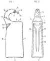
- the essentially cuboid-shaped container 1has a bottom 2 and a top wall 3 opposite it.
- the top wall 3is curved upward on the left-hand side in relation to FIG. 1 and has an indentation 4 in the middle part. From the upwardly curved part the top wall 3 extends a curved and tapering neck part.
- the outer end of the neck part 5is offset and has a hollow cylindrical projection 7 provided with a thread 6.
- An insert 8is inserted into the projection 7, which is described in more detail below with reference to FIG. 3.
- the radius of curvature of the center line of the neck part 5is 2 to 4 cm, preferably about 3 cm.
- the curvature of the neck part 5is designed such that the center line of the insert 8 is inclined downward by approximately 10 ° with respect to the horizontal and that the end of the insert 8 is located approximately above the lowest point of the indentation 4 mentioned. In this way, any drops of cleaning fluid that stick to the outer end of the insert 8 can drip into the indentation 4, where they then remain and possibly evaporate and therefore do not reach the rest of the outside of the container 1, which must be handled to use the container.
- the neck partIn the attachment area of the neck part 5 on the top wall 3, the neck part is partially surrounded by a groove 9, the ends of which open into the indentation 4 of the top wall 3.
- the purpose of the groove 9is that any drops of the cleaning liquid adhering to the neck part 5 get into the groove 9 and are guided through it into the indentation 4.
- transverse groove 11is arranged below the neck region of the neck part 5 in the narrow side 10 of the container 1 adjoining the neck region.
- the ends of the transverse groove 11each open into a curly longitudinal groove 12 which runs along the narrow side 10.
- the transverse groove 11 and the longitudinal grooves 12serve to remove cleaning liquid that overflows over the attachment area of the neck part 5. In this way it is avoided that those parts of the container 1 which are touched in use thereof are contaminated by dripping or overflowing cleaning liquid. Any cleaning liquid accumulated in the indentation 4 can drip into the toilet bowl to be cleaned the next time the container 1 is used.
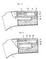
- the end of the neck part 5 of the container 1 according to FIG. 1is shown in FIG. 3 on a larger scale and partly in section.
- the insert 8has a passage channel 13 and a drip disc 14 is arranged at the outer end of the insert 8.
- the internal thread of a cover 15 covering the insert 8is screwed onto the thread 6 of the cylindrical extension 7 at the end of the neck part 5.
- the passage channel 13is widened outwards and forms a kind of funnel 16, in which the cleaning liquid located in this area is sucked back into the tank 1 when the pressure on the flexible tank 1 is released. If, after the container 1 has been erected, a drop of the cleaning liquid remains at the outer end of the passage 13, this drop is passed through the drip disk 14 into the indentation 4.
- a cylindrical pin 18extends in the direction of the cover opening.
- the pin 18projects into the passage 13 and closes it off.
- the inside of the end wall 17rests on the circular end face of the drip disk 14, so that the container 1 is sealed.
- an insert 19 shown in FIG. 4, which has a passage 20,can be inserted at the outer end of the neck part 5.
- the diameter of the passage 20is larger than the diameter of the passage 8. This makes it possible to use a powdered cleaning agent in the container, which is blown out through the passage 20 when the pressure is exerted on the container 1.
- the passage channel 20extends through a cylindrical extension 21 of the insert 19 and the inner end of the passage channel 20 is preferably widened inward so that the powdery cleaning agent can get out more easily.
- the cover 22has an internal thread which is screwed onto the thread 6 of the cylindrical projection 7 at the free end of the neck part 5.
- a pin 24protrudes in the direction of the cover opening. When the cover 22 is screwed on, the pin 24 projects into the passage channel 20 in order to close it.
- the diameter of the passage 20 in the cylindrical extension 21should be in the range of 2 to 5 mm, preferably about 3 mm.
- the proportion by weight of the grain sizes of 0.25 to 0.5 mm and 0.5 to 1.0 mm of the powdered cleaning agentshould each be at least 40%.
- the containertapers from the top wall 3 towards the bottom 2, so that a reasonable degree of filling of the bottle can be achieved.
- the powdery cleaning agentshould have as few fine-grained fractions as possible, ie fractions with a grain size of less than 0.25 mm, because otherwise the powdery cleaning agent will cake and become impermeable to air.
- the cleaning agentmust not be so coarse-grained that it drips off when it is applied to the damp toilet bowl and does not get caught. Even if the powdered detergent is in the container 1, the recess 4 in the top wall 3 and the grooves 9, 11 and 12 are not meaningless, because when using the container rinse water can reach the neck part 5 and the insert 19, which, as Described above with reference to the liquid detergent is kept away from the gripping surfaces of the container.
- the containeris intended to hold powdered cleaning agent, it is advantageous if an opening which can be closed by a countersunk cover is provided in the bottom 2 so that the powdered cleaning agent can be filled in without problems.
Landscapes
- Engineering & Computer Science (AREA)
- Mechanical Engineering (AREA)
- Ceramic Engineering (AREA)
- Detergent Compositions (AREA)
- Closures For Containers (AREA)
- Bidet-Like Cleaning Device And Other Flush Toilet Accessories (AREA)
- Polishing Bodies And Polishing Tools (AREA)
- Ultra Sonic Daignosis Equipment (AREA)
- Spinning Or Twisting Of Yarns (AREA)
- Containers And Packaging Bodies Having A Special Means To Remove Contents (AREA)
- Apparatus For Making Beverages (AREA)
- Medical Preparation Storing Or Oral Administration Devices (AREA)
Abstract
Translated fromGerman
Description
Translated fromGermanDie Erfindung betrifft einen Behälter gemäss dem Oberbegriff des Patentanspruches 1.The invention relates to a container according to the preamble of claim 1.
Es ist ein Behälter zum Aufnehmen eines flüssigen WC-Reinigungsmittels bekannt, der einen zweifach und jeweils in entgegengesetzter Richtung gebogenen Halsteil aufweist. Diese bekannte Formgebung ermöglicht eine Dosierung der Menge des Reinigungsmittels. Damit die gewünschte Dosierung erreicht wird, ist es notwendig, den Behälter relativ tief in die WC-Schüssel einzutauchen. Weiter kann nach dem Gebrauch allfällig am Ausguss abtropfende Reinigungsflüssigkeit auf der Aussenseite des Halsstückes ablaufen und zur Aussenfläche des Behälters gelangen.A container for holding a liquid toilet cleaning agent is known which has a neck part which is bent twice and in each case in the opposite direction. This known shape enables the amount of detergent to be metered. To achieve the desired dosage, it is necessary to immerse the container relatively deep in the toilet bowl. Furthermore, after use, any cleaning liquid dripping from the spout can run off on the outside of the neck piece and reach the outer surface of the container.
Es ist Aufgabe der Erfindung, einen eingangs genannten Behälter zu schaffen, welcher beim Gebrauch nicht so tief in die WC-Schüssel eingetaucht werden muss, und bei dem allfällig vom Ausguss abtropfende Flüssigkeit nicht ohne weiteres auf die Aussenseite des Behälters gelangen kann.It is an object of the invention to provide a container mentioned at the outset which does not have to be immersed so deeply in the toilet bowl during use and in which any liquid dripping from the spout cannot easily reach the outside of the container.
Der erfindungsgemässe Behälter ist durch die im kennzeichnenden Teil des Patentanspruches 1 angeführten Merkmale gekennzeichnet.The container according to the invention is characterized by the features stated in the characterizing part of patent claim 1.
Der Erfindungsgegenstand ist nachstehend mit Bezugnahme auf die Zeichnung beispielsweise näher erläutert. Es zeigen
- Fig. 1 ein Ausführungsbeispiel des erfindungsgemässen Behälters in der Ansicht, wobei der Deckel abgenommen ist,
- Fig. 2 die Seitenansicht des Behälters gemäss der Fig. 1,
- Fig. 3 das eine Ende des Halsteiles des Behälters gemäss der Fig. 1 teilweise im Schnitt und in einem grösseren Massstab gezeichnet und
- Fig. 4 das eine Ende des Halsteiles eines anderen Ausführungsbeispieles des Behälters in der gleichen Darstellung wie die Fig. 3.
- 1 shows an embodiment of the container according to the invention in the view, with the lid removed,
- 2 shows the side view of the container according to FIG. 1,
- Fig. 3 shows the one end of the neck part of the container according to FIG. 1 partially in section and on a larger scale and
- F ig. 4 the one end of the neck part of another exemplary embodiment of the container in the same representation as FIG. 3.
Die Fig. 1 und 2 zeigen die Ansicht und die Seitenansicht eines ersten Ausführungsbeispieles des erfindungsgemässen Behälters. Der im wesentlichen quaderförmig ausgebildete Behälter 1 besitzt einen Boden 2 und eine diesem gegenüberliegende Deckwand 3. Die Deckwand 3 ist bezogen auf die Fig. 1 auf der linken Seite nach oben gekrümmt und besitzt im mittleren Teil eine Einbuchtung 4. Aus dem nach oben gekrümmten Teil der Deckwand 3 erstreckt sich ein gekrümmter und sich verjüngender Halsteil. Das äussere Ende des Halsteiles 5 ist abgesetzt und besitzt einen mit einem Gewinde 6 versehenen hohlzylindrischen Ansatz 7. In den Ansatz 7 ist ein Einsatzstück 8 eingesetzt, das weiter unten mit Bezugnahme auf die Fig. 3 näher beschrieben ist.1 and 2 show the view and the side view of a first embodiment of the container according to the invention. The essentially cuboid-shaped container 1 has a
Der Krümmungsradius der Mittellinie des Halsteiles 5 beträgt 2 bis 4 cm, vorzugsweise etwa 3 cm. Die Krümmung des Halsteiles 5 ist so ausgebildet, dass die Mittellinie des Einsatzstückes 8 bezüglich der Horizontalen etwa 10° nach unten geneigt ist und dass sich das Ende des Einsatzstückes 8 etwa über der tiefsten Stelle der genannten Einbuchtung 4 befindet. Auf diese Weise können allfällig am äusseren Ende des Einsatzstückes 8 haftenbleibende Tropfen der Reinigungsflüssigkeit in die Einbuchtung 4 abtropfen, wo sie dann liegen bleiben und gegebenenfalls verdunsten und daher nicht auf die übrige Aussenseite des Behälters 1 gelangen, welche zum Gebrauch des Behälters angefasst werden muss.The radius of curvature of the center line of the
Im Ansatzbereich des Halsteiles 5 an der Deckwand 3 ist der Halsteil teilweise von einer Nut 9 umgeben, deren Enden in die genannte Einbuchtung 4 der Deckwand 3 münden. Der Zweck der Nut 9 ist, dass allfällig am Halsteil 5 haftende Tropfen der Reinigungsflüssigkeit in die Nut 9 gelangen und durch sie in die Einbuchtung 4 geleitet werden.In the attachment area of the
Unterhalb des Ansatzbereiches des Halsteiles 5 ist in der an den Halsbereich angrenzenden Schmalseite 10 des Behälters 1 eine etwa horizontal verlaufende Quernut 11 angeordnet. Die Enden der Quernut 11 münden in je eine geschweifte und im übrigen längs der genannten Schmalseite 10 verlaufende Längsnut 12 ein. Die Quernut 11 und die Längsnuten 12 dienen im Extremfall zum Abführen von über den Ansatzbereich des Halsteiles 5 überlaufender Reinigungsflüssigkeit. Auf diese Weise wird vermieden, dass jene Teile des Behälters 1, die im Gebrauch desselben angefasst werden, von abtropfender bzw. überlaufender Reinigungsflüssigkeit verschmutzt werden. Allfällig sich in der Einbuchtung 4 angesammelte Reinigungsflüssigkeit kann beim nächsten Gebrauch des Behälters 1 über die Nut 9 in'die zu reinigende WC-Schüssel abtropfen.An approximately horizontal
Das Ende des Halsteiles 5 des Behälters 1 gemäss der Fig. 1 ist in der Fig. 3 in einem grösseren Massstab und teilweise im Schnitt dargestellt. Das Einsatzstück 8 besitzt einen Durchtrittskanal 13 und am äusseren Ende des Einsatzstückes 8 ist eine Tropfscheibe 14 angeordnet. Auf das Gewinde 6 des zylindrischen Ansatzes 7 am Ende des Halsteiles 5 ist das Innengewinde eines das Einsatzstück 8 abdeckenden Deckels 15 aufgeschraubt. Im Bereich der Tropfscheibe 14 ist der Durchtrittskanal 13 nach aussen hin erweitert und bildet eine Art Trichter 16, in welchen beim Loslassen des Druckes auf den nachgiebigen Behälter 1 die gerade in diesem Bereich befindliche Reinigungsflüssigkeit in den Behälter 1 zurückgesogen wird. Sollte nach dem Aufrichten des Behälters 1 noch ein Tropfen der Reinigungsflüssigkeit am äusseren Ende des Durchtrittskanales 13 verbleiben, so wird dieser Tropfen durch die Tropfscheibe 14 in die Einbuchtung 4 geleitet.The end of the
Auf der Innenseite der Abschlusswand 17 des Deckels 15 erstreckt sich ein zylindrischer Zapfen 18 in Richtung der Deckelöffnung. Bei aufgeschraubtem Deckel 15 ragt der Zapfen 18 in den Durchtrittskanal 13 hinein und schliesst diesen ab. Weiter liegt die Innenseite der Abschlusswand 17 an der kreisringförmigen Stirnseite der Tropfscheibe 14 auf, so dass sich ein dichter Verschluss des Behälters 1 ergibt.On the inside of the
Anstelle des Einsatzstückes 8 kann am äusseren Ende des Halsteiles 5 ein in der Fig. 4 dargestelltes Einsatzstück 19 eingesetzt sein, das einen Durchtrittskanal 20 aufweist. Der Durchmesser des Durchtrittskanales 20 ist grösser als der Durchmesser des Durchtrittskanals 8. Dadurch ist es möglich, im Behälter ein pulverförmiges Reinigungsmittel zu verwenden, welches beim auf den Behälter 1 ausgeübten Druck durch den Durchlasskanal 20 ausgeblasen wird. Der Durchtrittskanal 20 erstreckt sich durch einen zylindrischen Ansatz 21 des Einsatzstückes 19 und das innere Ende des Durchtrittskanales 20 ist vorzugsweise nach innen zu erweitert, damit das pulverförmige Reinigungsmittel leichter nach aussen gelangen kann.Instead of the
Der Deckel 22 besitzt ein Innengewinde, das auf das Gewinde 6 des zylindrischen Ansatzes 7 am freien Ende des Halsteiles 5 aufgeschraubt ist. Auf der Innenseite der Abschlusswand 23 des Deckels 22 steht ein Zapfen 24 in Richtung zur Deckelöffnung vor. Bei aufgeschraubtem Deckel 22 ragt der Zapfen 24 zum Verschliessen des Durchtrittskanales 20 in diesen hinein.The
Wenn sich im Behälter 1 ein pulverförmiges Reinigungsmittel befindet, so sollte der Durchmesser des Durchtrittskanales 20 im zylindrischen Ansatz 21 im Bereich von 2 bis 5 mm liegen, vorzugsweise etwa 3 mm betragen. Der Gewichtsanteil der Korngrössen von 0,25 bis 0,5 mm und 0,5 bis 1,0 mm des pulverförmigen Reinigungsmittels sollten je mindestens 40 % betragen. Zudem ist es vorteilhaft, wenn der Behälter sich von der Deckwand 3 gegen den Boden 2 hin verjüngt, so dass ein vernünftiger Füllgrad der Flasche erreicht werden kann. Beim Kippen des Behälters entsteht auf diese Weise ein ausreichend grosser Luftraum im hinteren Ende des Behälters und beim Zusammendrücken des Behälters wird Luft durch die Pulvermischung hindurchgepresst, so dass im Durchlasskanal 20 die Pulverpartikel mitgerissen werden. Das pulverförmige Reinigungsmittel soll möglichst wenig feinkörnige Anteile, d.h. Anteile mit einer Korngrösse von weniger als 0,25 mm, aufweisen, weil sonst das pulverförmige Reinigungsmittel zusammenbackt und luftundurchlässig wird. Andererseits darf das Reinigungsmittel nicht so grobkörnig sein, dass es beim Aufbringen auf die feuchte WC-Schüssel abrieselt und nicht hängen bleibt. Auch wenn sich im Behälter 1 das pulverförmige Reinigungsmittel befindet, sind die Vertiefung 4 in der Deckwand 3 und die Nuten 9, 11 und 12 nicht sinnlos, weil beim Gebrauch des Behälters Spülwasser an den Halsteil 5 und das Einsatzstück 19 gelangen kann, welches, wie weiter oben mit Bezug auf das flüssige Reinigungsmittel beschrieben, von den Griffflächen des Behälters ferngehalten wird.If there is a powdery cleaning agent in the container 1, the diameter of the
Wenn der Behälter zum Aufnehmen von pulverförmigem Reinigungsmittel vorgesehen ist, so ist es vorteilhaft, wenn im Boden 2 eine durch einen versenkten Deckel verschliessbare Oeffnung vorgesehen ist, damit das pulverförmige Reinigungsmittel problemlos eingefüllt werden kann.If the container is intended to hold powdered cleaning agent, it is advantageous if an opening which can be closed by a countersunk cover is provided in the
Claims (7)
Translated fromGermanPriority Applications (1)
| Application Number | Priority Date | Filing Date | Title |
|---|---|---|---|
| AT84201637TATE26091T1 (en) | 1983-11-25 | 1984-11-13 | CONTAINER FOR A LIQUID OR POWDER TOILET CLEANER. |
Applications Claiming Priority (2)
| Application Number | Priority Date | Filing Date | Title |
|---|---|---|---|
| CH632583 | 1983-11-25 | ||
| CH6325/83 | 1983-11-25 |
Publications (3)
| Publication Number | Publication Date |
|---|---|
| EP0144104A2true EP0144104A2 (en) | 1985-06-12 |
| EP0144104A3 EP0144104A3 (en) | 1985-08-14 |
| EP0144104B1 EP0144104B1 (en) | 1987-03-25 |
Family
ID=4307776
Family Applications (1)
| Application Number | Title | Priority Date | Filing Date |
|---|---|---|---|
| EP84201637AExpiredEP0144104B1 (en) | 1983-11-25 | 1984-11-13 | Container for a liquid or powdery toilet cleanser |
Country Status (9)
| Country | Link |
|---|---|
| US (1) | US4600128A (en) |
| EP (1) | EP0144104B1 (en) |
| JP (1) | JPS60110279U (en) |
| AT (1) | ATE26091T1 (en) |
| AU (1) | AU3535784A (en) |
| CA (1) | CA1229072A (en) |
| DE (1) | DE3462771D1 (en) |
| DK (1) | DK158634C (en) |
| FI (1) | FI76537C (en) |
Cited By (3)
| Publication number | Priority date | Publication date | Assignee | Title |
|---|---|---|---|---|
| WO1993025441A1 (en)* | 1992-06-12 | 1993-12-23 | Hem Gmbh | Squeeze bottle with dosing device and squirting closure |
| DE10159988A1 (en)* | 2001-12-06 | 2003-06-26 | Mewes Axel | Containers for storing and pouring liquids |
| KR100766843B1 (en)* | 2005-02-14 | 2007-10-17 | 에어 프로덕츠 앤드 케미칼스, 인코오포레이티드 | Preparation of metal silicon nitride films via cyclic deposition |
Families Citing this family (19)
| Publication number | Priority date | Publication date | Assignee | Title |
|---|---|---|---|---|
| US4925063A (en)* | 1988-12-01 | 1990-05-15 | Athar Mohammad Ali | Container having a dual purpose cap and a dripless spout |
| US7296706B2 (en)* | 2004-02-24 | 2007-11-20 | Nordson Corporation | Method and system for supporting and/or aligning components of a liquid dispensing system |
| USD536421S1 (en) | 2004-04-02 | 2007-02-06 | Nordson Corporation | Intake portion of a liquid dispensing valve |
| US7052549B2 (en)* | 2004-04-22 | 2006-05-30 | Nordson Corporation | Dispensing apparatus and manifold having an adhesive catch groove |
| US7278550B2 (en)* | 2004-11-11 | 2007-10-09 | Nordson Corporation | Method and system for aligning components of a liquid dispensing system |
| US7306121B2 (en)* | 2005-03-21 | 2007-12-11 | Hygiene-Technik Inc. | Gooseneck squeezable dispenser |
| GB0515750D0 (en) | 2005-07-30 | 2005-09-07 | Dyson Technology Ltd | Drying apparatus |
| GB0515749D0 (en) | 2005-07-30 | 2005-09-07 | Dyson Technology Ltd | Drying apparatus |
| GB2428569B (en)* | 2005-07-30 | 2009-04-29 | Dyson Technology Ltd | Dryer |
| GB0515744D0 (en) | 2005-07-30 | 2005-09-07 | Dyson Technology Ltd | Dryer |
| GB0515754D0 (en) | 2005-07-30 | 2005-09-07 | Dyson Technology Ltd | Drying apparatus |
| US7140952B1 (en) | 2005-09-22 | 2006-11-28 | Pratt & Whitney Canada Corp. | Oxidation protected blade and method of manufacturing |
| US7665638B2 (en)* | 2005-10-28 | 2010-02-23 | The Sun Products Corporation | Packaged liquid laundry compositions |
| US20070095784A1 (en) | 2005-10-28 | 2007-05-03 | Conopco, Inc. | Package for liquid laundry products |
| GB2434094A (en) | 2006-01-12 | 2007-07-18 | Dyson Technology Ltd | Drying apparatus with sound-absorbing material |
| EP2296820B1 (en)* | 2008-06-18 | 2019-12-11 | Silgan Dispensing Systems Slatersville LLC | Dispensing closure for a fan spray nozzle |
| US20100187195A1 (en)* | 2009-01-28 | 2010-07-29 | Jamieson John E | Bottle With Directed Pour Spout |
| USD841471S1 (en) | 2017-02-24 | 2019-02-26 | S. C. Johnson & Son, Inc. | Bottle |
| USD845135S1 (en) | 2017-02-24 | 2019-04-09 | S. C. Johnson & Son, Inc. | Bottle neck with cap |
Family Cites Families (14)
| Publication number | Priority date | Publication date | Assignee | Title |
|---|---|---|---|---|
| US280048A (en)* | 1883-06-26 | Glass-bodied vessel for oil | ||
| DE23459C (en)* | W. HIRSCH in Berlin | Drip catcher for bottles | ||
| US866807A (en)* | 1907-04-24 | 1907-09-24 | David L Pitts | Drip cup or receptacle. |
| US1165787A (en)* | 1914-09-30 | 1915-12-28 | John H Lance | Pitcher. |
| FR1014472A (en)* | 1947-01-14 | 1952-08-18 | Recovery pouring container | |
| US2722346A (en)* | 1953-04-10 | 1955-11-01 | Yokota Sumio | Pouring spout for bottle |
| US2750063A (en)* | 1955-07-14 | 1956-06-12 | Opsitnik William | Non-drip insert for bottles |
| US2917198A (en)* | 1958-03-03 | 1959-12-15 | Linden H Chandler | Fitments and closures |
| JPS585936B2 (en)* | 1974-04-30 | 1983-02-02 | 三菱レイヨン株式会社 | Nannensei glass sensor |
| US4034901A (en)* | 1975-04-18 | 1977-07-12 | Norman Kirk | Dripless spout for paint cans |
| JPS522756A (en)* | 1975-06-25 | 1977-01-10 | Nippon Steel Corp | System for measuring thickness of surface coated membrane |
| CH638114A5 (en)* | 1980-07-03 | 1983-09-15 | Duering Ag | HAND CRUSH BOTTLE FOR GENERATING A DIRECTED JET OF LIQUID. |
| CA1177445A (en)* | 1981-03-16 | 1984-11-06 | George W. Macfarlane | Liquid storage container and dispenser |
| DE3138873A1 (en)* | 1981-09-30 | 1983-04-14 | Wella Ag, 6100 Darmstadt | Screw closure cap |
- 1984
- 1984-11-13DEDE8484201637Tpatent/DE3462771D1/ennot_activeExpired
- 1984-11-13AUAU35357/84Apatent/AU3535784A/ennot_activeAbandoned
- 1984-11-13EPEP84201637Apatent/EP0144104B1/ennot_activeExpired
- 1984-11-13ATAT84201637Tpatent/ATE26091T1/enactive
- 1984-11-15USUS06/672,293patent/US4600128A/ennot_activeExpired - Fee Related
- 1984-11-16FIFI844502Apatent/FI76537C/ennot_activeIP Right Cessation
- 1984-11-21CACA000468331Apatent/CA1229072A/ennot_activeExpired
- 1984-11-22JPJP1984178107Upatent/JPS60110279U/enactivePending
- 1984-11-23DKDK557584Apatent/DK158634C/ennot_activeIP Right Cessation
Cited By (5)
| Publication number | Priority date | Publication date | Assignee | Title |
|---|---|---|---|---|
| WO1993025441A1 (en)* | 1992-06-12 | 1993-12-23 | Hem Gmbh | Squeeze bottle with dosing device and squirting closure |
| DE10159988A1 (en)* | 2001-12-06 | 2003-06-26 | Mewes Axel | Containers for storing and pouring liquids |
| US7293679B2 (en) | 2001-12-06 | 2007-11-13 | Axel Mewes | Container for storing and pouring liquids |
| DE10159988B4 (en)* | 2001-12-06 | 2016-01-07 | Kautex Textron Gmbh & Co. Kg | Container for storing and pouring liquids |
| KR100766843B1 (en)* | 2005-02-14 | 2007-10-17 | 에어 프로덕츠 앤드 케미칼스, 인코오포레이티드 | Preparation of metal silicon nitride films via cyclic deposition |
Also Published As
| Publication number | Publication date |
|---|---|
| DK557584A (en) | 1985-05-26 |
| FI76537B (en) | 1988-07-29 |
| EP0144104A3 (en) | 1985-08-14 |
| DK158634B (en) | 1990-06-25 |
| DK557584D0 (en) | 1984-11-23 |
| JPS60110279U (en) | 1985-07-26 |
| ATE26091T1 (en) | 1987-04-15 |
| US4600128A (en) | 1986-07-15 |
| DK158634C (en) | 1990-11-26 |
| FI844502A0 (en) | 1984-11-16 |
| FI844502L (en) | 1985-05-26 |
| DE3462771D1 (en) | 1987-04-30 |
| CA1229072A (en) | 1987-11-10 |
| EP0144104B1 (en) | 1987-03-25 |
| AU3535784A (en) | 1985-05-30 |
| FI76537C (en) | 1988-11-10 |
Similar Documents
| Publication | Publication Date | Title |
|---|---|---|
| EP0144104B1 (en) | Container for a liquid or powdery toilet cleanser | |
| EP0336415A2 (en) | Spraying device | |
| EP0259852A1 (en) | Multichamber container | |
| DE2851449C2 (en) | Bottle dosing cap | |
| EP1451070A1 (en) | Container for storing and pouring liquids | |
| EP0103600A1 (en) | Cap intended to be placed on the central outlet opening of a liquid container. | |
| DE60222170T2 (en) | DISTRIBUTION DEVICE FOR LIQUID ACTIVE SUBSTANCES FOR WC BASIN | |
| DE2009245A1 (en) | Container for holding liquid media | |
| EP0286843A1 (en) | Closure with dosing cap | |
| DE60101016T2 (en) | MIXING APPARATUS | |
| DE102005004487A1 (en) | Container for cleaning agents | |
| DE602004001402T2 (en) | LIQUID ACTIVE FABRIC DISTRIBUTION DEVICE FOR TOILET BASIN | |
| DE29704163U1 (en) | Container attachment for open liquid containers, in particular paint cans | |
| CH653881A5 (en) | DEVICE FOR STORING AND VIBRATING MIXING OF THE COMPONENTS OF AMALGAMS FOR DENTAL PURPOSES. | |
| CH621985A5 (en) | Portion package for drainage pipe cleaning agents | |
| DE3620110A1 (en) | Insert for an apparatus for purifying a liquid | |
| EP0274070B1 (en) | Measuring device for a bottle neck, for dispensing pasty or viscous matter | |
| DE8603167U1 (en) | Pouring device for containers | |
| DE2742657C2 (en) | ||
| DE4113860C2 (en) | Device for cleaning a liquid | |
| DE3214345A1 (en) | SPREADER | |
| DE713768C (en) | Liquid dispenser | |
| DE842281C (en) | Milking bucket with strainer | |
| DE10246581A1 (en) | Arrangement for delivery of part volumes of fluid from bottle by tipping it has standpipe closed at bottom and communicating with atmosphere and on section located above bottom of bottle has recess facing bottle wall side | |
| DE7615313U1 (en) | Litter dispenser |
Legal Events
| Date | Code | Title | Description |
|---|---|---|---|
| PUAI | Public reference made under article 153(3) epc to a published international application that has entered the european phase | Free format text:ORIGINAL CODE: 0009012 | |
| PUAL | Search report despatched | Free format text:ORIGINAL CODE: 0009013 | |
| AK | Designated contracting states | Designated state(s):AT BE CH DE FR GB IT LI LU NL SE | |
| AK | Designated contracting states | Designated state(s):AT BE CH DE FR GB IT LI LU NL SE | |
| 17P | Request for examination filed | Effective date:19851012 | |
| 17Q | First examination report despatched | Effective date:19860611 | |
| GRAA | (expected) grant | Free format text:ORIGINAL CODE: 0009210 | |
| AK | Designated contracting states | Kind code of ref document:B1 Designated state(s):AT BE CH DE FR GB IT LI LU NL SE | |
| REF | Corresponds to: | Ref document number:26091 Country of ref document:AT Date of ref document:19870415 Kind code of ref document:T | |
| REF | Corresponds to: | Ref document number:3462771 Country of ref document:DE Date of ref document:19870430 | |
| ITF | It: translation for a ep patent filed | ||
| ET | Fr: translation filed | ||
| PG25 | Lapsed in a contracting state [announced via postgrant information from national office to epo] | Ref country code:LU Free format text:LAPSE BECAUSE OF NON-PAYMENT OF DUE FEES Effective date:19871130 | |
| PLBE | No opposition filed within time limit | Free format text:ORIGINAL CODE: 0009261 | |
| STAA | Information on the status of an ep patent application or granted ep patent | Free format text:STATUS: NO OPPOSITION FILED WITHIN TIME LIMIT | |
| 26N | No opposition filed | ||
| PGFP | Annual fee paid to national office [announced via postgrant information from national office to epo] | Ref country code:FR Payment date:19891008 Year of fee payment:6 | |
| PGFP | Annual fee paid to national office [announced via postgrant information from national office to epo] | Ref country code:DE Payment date:19891031 Year of fee payment:6 | |
| PGFP | Annual fee paid to national office [announced via postgrant information from national office to epo] | Ref country code:CH Payment date:19891110 Year of fee payment:6 | |
| PGFP | Annual fee paid to national office [announced via postgrant information from national office to epo] | Ref country code:AT Payment date:19891128 Year of fee payment:6 | |
| PGFP | Annual fee paid to national office [announced via postgrant information from national office to epo] | Ref country code:GB Payment date:19901016 Year of fee payment:7 | |
| PGFP | Annual fee paid to national office [announced via postgrant information from national office to epo] | Ref country code:SE Payment date:19901019 Year of fee payment:7 | |
| PGFP | Annual fee paid to national office [announced via postgrant information from national office to epo] | Ref country code:BE Payment date:19901026 Year of fee payment:7 | |
| PGFP | Annual fee paid to national office [announced via postgrant information from national office to epo] | Ref country code:LU Payment date:19901106 Year of fee payment:7 | |
| PG25 | Lapsed in a contracting state [announced via postgrant information from national office to epo] | Ref country code:AT Effective date:19901113 | |
| ITTA | It: last paid annual fee | ||
| PG25 | Lapsed in a contracting state [announced via postgrant information from national office to epo] | Ref country code:LI Effective date:19901130 Ref country code:CH Effective date:19901130 | |
| PGFP | Annual fee paid to national office [announced via postgrant information from national office to epo] | Ref country code:NL Payment date:19901130 Year of fee payment:7 | |
| EPTA | Lu: last paid annual fee | ||
| PG25 | Lapsed in a contracting state [announced via postgrant information from national office to epo] | Ref country code:FR Effective date:19910731 | |
| REG | Reference to a national code | Ref country code:CH Ref legal event code:PL | |
| PG25 | Lapsed in a contracting state [announced via postgrant information from national office to epo] | Ref country code:DE Effective date:19910801 | |
| REG | Reference to a national code | Ref country code:FR Ref legal event code:ST | |
| PG25 | Lapsed in a contracting state [announced via postgrant information from national office to epo] | Ref country code:GB Effective date:19911113 | |
| PG25 | Lapsed in a contracting state [announced via postgrant information from national office to epo] | Ref country code:SE Effective date:19911114 | |
| PG25 | Lapsed in a contracting state [announced via postgrant information from national office to epo] | Ref country code:BE Effective date:19911130 | |
| BERE | Be: lapsed | Owner name:SIPURO A.G. Effective date:19911130 | |
| PG25 | Lapsed in a contracting state [announced via postgrant information from national office to epo] | Ref country code:NL Effective date:19920601 | |
| GBPC | Gb: european patent ceased through non-payment of renewal fee | ||
| NLV4 | Nl: lapsed or anulled due to non-payment of the annual fee | ||
| EUG | Se: european patent has lapsed | Ref document number:84201637.0 Effective date:19920604 |