EP0143895B1 - Portable infusion apparatus - Google Patents
Portable infusion apparatusDownload PDFInfo
- Publication number
- EP0143895B1 EP0143895B1EP84109715AEP84109715AEP0143895B1EP 0143895 B1EP0143895 B1EP 0143895B1EP 84109715 AEP84109715 AEP 84109715AEP 84109715 AEP84109715 AEP 84109715AEP 0143895 B1EP0143895 B1EP 0143895B1
- Authority
- EP
- European Patent Office
- Prior art keywords
- threaded rod
- holder
- nut
- injection ampoule
- casing
- Prior art date
- Legal status (The legal status is an assumption and is not a legal conclusion. Google has not performed a legal analysis and makes no representation as to the accuracy of the status listed.)
- Expired
Links
- 238000001802infusionMethods0.000titleclaimsdescription8
- 239000003708ampulSubstances0.000claimsdescription40
- 238000002347injectionMethods0.000claimsdescription13
- 239000007924injectionSubstances0.000claimsdescription13
- 239000007788liquidSubstances0.000claimsdescription5
- NOESYZHRGYRDHS-UHFFFAOYSA-NinsulinChemical compoundN1C(=O)C(NC(=O)C(CCC(N)=O)NC(=O)C(CCC(O)=O)NC(=O)C(C(C)C)NC(=O)C(NC(=O)CN)C(C)CC)CSSCC(C(NC(CO)C(=O)NC(CC(C)C)C(=O)NC(CC=2C=CC(O)=CC=2)C(=O)NC(CCC(N)=O)C(=O)NC(CC(C)C)C(=O)NC(CCC(O)=O)C(=O)NC(CC(N)=O)C(=O)NC(CC=2C=CC(O)=CC=2)C(=O)NC(CSSCC(NC(=O)C(C(C)C)NC(=O)C(CC(C)C)NC(=O)C(CC=2C=CC(O)=CC=2)NC(=O)C(CC(C)C)NC(=O)C(C)NC(=O)C(CCC(O)=O)NC(=O)C(C(C)C)NC(=O)C(CC(C)C)NC(=O)C(CC=2NC=NC=2)NC(=O)C(CO)NC(=O)CNC2=O)C(=O)NCC(=O)NC(CCC(O)=O)C(=O)NC(CCCNC(N)=N)C(=O)NCC(=O)NC(CC=3C=CC=CC=3)C(=O)NC(CC=3C=CC=CC=3)C(=O)NC(CC=3C=CC(O)=CC=3)C(=O)NC(C(C)O)C(=O)N3C(CCC3)C(=O)NC(CCCCN)C(=O)NC(C)C(O)=O)C(=O)NC(CC(N)=O)C(O)=O)=O)NC(=O)C(C(C)CC)NC(=O)C(CO)NC(=O)C(C(C)O)NC(=O)C1CSSCC2NC(=O)C(CC(C)C)NC(=O)C(NC(=O)C(CCC(N)=O)NC(=O)C(CC(N)=O)NC(=O)C(NC(=O)C(N)CC=1C=CC=CC=1)C(C)C)CC1=CN=CN1NOESYZHRGYRDHS-UHFFFAOYSA-N0.000claimsdescription4
- 102000004877InsulinHuman genes0.000claimsdescription2
- 108090001061InsulinProteins0.000claimsdescription2
- 229940125396insulinDrugs0.000claimsdescription2
- 239000011796hollow space materialSubstances0.000claims4
- 239000007921spraySubstances0.000description25
- 238000003780insertionMethods0.000description4
- 230000037431insertionEffects0.000description4
- 238000006073displacement reactionMethods0.000description3
- 238000005192partitionMethods0.000description3
- 230000006870functionEffects0.000description2
- 238000009434installationMethods0.000description2
- XAGFODPZIPBFFR-UHFFFAOYSA-NaluminiumChemical compound[Al]XAGFODPZIPBFFR-UHFFFAOYSA-N0.000description1
- 229910052782aluminiumInorganic materials0.000description1
- 230000005540biological transmissionEffects0.000description1
- 230000008878couplingEffects0.000description1
- 238000010168coupling processMethods0.000description1
- 238000005859coupling reactionMethods0.000description1
- 230000003247decreasing effectEffects0.000description1
- 230000000881depressing effectEffects0.000description1
- 239000013013elastic materialSubstances0.000description1
- 238000004519manufacturing processMethods0.000description1
- 230000001681protective effectEffects0.000description1
- 230000000284resting effectEffects0.000description1
- 238000007789sealingMethods0.000description1
- 239000000243solutionSubstances0.000description1
Images

Classifications
- A—HUMAN NECESSITIES
- A61—MEDICAL OR VETERINARY SCIENCE; HYGIENE
- A61M—DEVICES FOR INTRODUCING MEDIA INTO, OR ONTO, THE BODY; DEVICES FOR TRANSDUCING BODY MEDIA OR FOR TAKING MEDIA FROM THE BODY; DEVICES FOR PRODUCING OR ENDING SLEEP OR STUPOR
- A61M5/00—Devices for bringing media into the body in a subcutaneous, intra-vascular or intramuscular way; Accessories therefor, e.g. filling or cleaning devices, arm-rests
- A61M5/14—Infusion devices, e.g. infusing by gravity; Blood infusion; Accessories therefor
- A61M5/142—Pressure infusion, e.g. using pumps
- A61M5/145—Pressure infusion, e.g. using pumps using pressurised reservoirs, e.g. pressurised by means of pistons
- A61M5/1452—Pressure infusion, e.g. using pumps using pressurised reservoirs, e.g. pressurised by means of pistons pressurised by means of pistons
- A61M5/14546—Front-loading type injectors
- A—HUMAN NECESSITIES
- A61—MEDICAL OR VETERINARY SCIENCE; HYGIENE
- A61M—DEVICES FOR INTRODUCING MEDIA INTO, OR ONTO, THE BODY; DEVICES FOR TRANSDUCING BODY MEDIA OR FOR TAKING MEDIA FROM THE BODY; DEVICES FOR PRODUCING OR ENDING SLEEP OR STUPOR
- A61M5/00—Devices for bringing media into the body in a subcutaneous, intra-vascular or intramuscular way; Accessories therefor, e.g. filling or cleaning devices, arm-rests
- A61M5/14—Infusion devices, e.g. infusing by gravity; Blood infusion; Accessories therefor
- A61M5/142—Pressure infusion, e.g. using pumps
- A61M5/14244—Pressure infusion, e.g. using pumps adapted to be carried by the patient, e.g. portable on the body
Definitions
- the inventionrelates to a portable infusion device for automatically dispensing liquid according to the first part of patent claim 1.
- a device of this typeis known from GB-A-2 094 628. It has a housing with a removable lid, into which a syringe can be inserted so that its outlet piece protrudes through a hole in the side wall of the housing.
- the head of the piston rod of the syringeis inserted into an attachment of a nut of a screw transmission, the threaded rod of which can be rotated by means of a drive device acting on a pinion seated on it.
- the threaded rodis turned, the piston rod of the syringe is advanced through the nut.
- the devicecan only be operated with a complete syringe with a piston rod and the nut is eccentrically loaded by the piston rod. so that the driving force has to overcome considerable friction and the feed is susceptible to failure as a result of wear or tilting.
- screwing back the nut to insert a new (full) syringeis time-consuming.
- a different type of infusion deviceis known from EP-A 42 282.
- the syringes to be used for the devicehave a flange at the rear end of the housing, which is inserted in grooves on opposite housing walls of the device.
- the piston rod of the syringeis placed on a pinion of a drive device arranged on the bottom of the housing between the opposite walls and is pressed onto the pinion by means of a depressing member so that it can advance the piston rod, which is made of plastic and is smooth in the longitudinal direction.
- the devicehas over others, e.g. B.
- the inventionhas for its object to provide a simple, short and small device that can be operated with a spray ampoule and that ensures reliable advancement of the piston of the spray ampoule.
- the spray ampoulediffers from a conventional ampoule in that it is provided with a sealing piston at one end for use as a syringe and for the introduction of a Piston rod is open and is equipped with an outlet piece at the other end. It differs from a complete syringe in that it does not have a piston rod. It is also called carpule.
- the device shown in FIGS. 1 to 3has a housing 1 in which a drive device is arranged.
- the drive device(not shown) has a stepper motor which is powered by a battery and controlled by a control device and which drives a pinion 2.
- the control devicecan set the clock frequency of the control pulses controlling the stepper motor in the course of the day according to a function of the time defined by the doctor and for this purpose have a clock and a memory in which for certain times, e.g. B. every hour of the day, certain infusion rates set by the doctor are stored as control values.
- the rear (in the drawing upper) part 3 of the housing 1has a cylindrical cavity 4 which is closed at the rear end and at the front end in a cylindrical cavity 5 of the front (in the drawing lower) part 6 of the housing which is coaxial with it 1 opens, the cavity wall, as described in more detail below, a holder for a replaceable Spray ampoule and a nut forms.
- a driving sleeve 8is rotatably mounted in the cavity 4. on which a ring gear 9 which engages in the pinion 2 is formed and runs in a recess in the housing part 3 which is adapted to it, the walls of the recess preventing axial displacement of the ring gear 9 and thus also the sleeve 8.
- the housing 1is composed of two pieces, between which the recess is formed, and which are joined together, for example glued, after the sleeve 8 has been inserted.
- a threaded rod 11is rotatably but slidably inserted.
- the threaded rod 11is flattened on opposite sides and the cross section of the bore of the driving sleeve is adapted accordingly.
- the threaded rod 11thus has two flat, parallel, smooth longitudinal surfaces, on which it is carried along by the corresponding flat inner wall surfaces of the sleeve 8, and two threaded cylinder jacket segments which are at a distance from the two smooth, cylindrical inner wall surfaces of the sleeve 8.
- a disc 17 formed with a coaxial to the threaded rod 11, threadless pin 13, which can be inserted into the blind hole provided for receiving a piston rod of the piston 14 of a spray ampoule 15,is rotatably mounted .
- the diameter of the disc 17is smaller than the diameter of the piston 14, so that the disc resting on the piston 14 can be inserted into the ampoule tube.
- a nut 21 provided with external teeth 20is screwed onto the lower part of the threaded rod 11 adjacent to the disk 17 in the drawing.
- the external toothing 20 of the nut 21is brought into engagement with a corresponding internal toothing 22 on the outer surface of the inner wall of the housing part 6 adjoining the rear end wall 23 of the cylindrical cavity 5.
- the thickness of the nut 21is larger than the tooth width of the inner toothing 22, and the diameter of the tip circle of the outer toothing 20 corresponds approximately to the outer diameter of the spray ampoule 15, so that the nut 21 after the insertion of the spray ampoule 15 described below between the rear end and the rear end wall 23 of the Cavity 5 is clamped secured against axial displacement.
- connection part 27provided with an external thread 26 is screwed.
- Thishas a cylindrical cavity for receiving the aluminum cap 29 of the spray ampoule 15 and a conical cavity for receiving the plastic outlet piece 30 of the spray ampoule 15, the so-called luer.
- a catheter 32which communicates with the conical cavity and is formed by a flexible tube, is welded into the front end of the connecting part 27 and adjoins the outlet opening or is at a small distance from it when the luer 30 lies tightly against the conical cavity walls.
- the spray ampoule 15 shown in the drawingis such a commercially available spray ampoule, the piston 14 of which has a threaded blind hole for a piston rod.
- Z. B. insulin filled syringe vialsare used that are supplied without a piston rod.
- the patientcan also use empty syringe vials that are supplied with a standard piston rod that can be screwed into the threaded blind hole. After filling the injection ampoule, the patient then only has to unscrew the piston rod from the threaded blind hole.
- the filled syringe ampoule 15is inserted into the connecting part 27 with its luer 30 - after removing a protective cap closing it. Thereafter, the threaded rod 11, on which the nut 21 is seated against the disk 17, is inserted with the pin 13 rotatably mounted on it in the blind hole of the piston 14, so that the disk 17 rests on the piston 14. Now, the spray ampoule 15 is inserted into the cavity 5 with the aid of the non-slip connection part 27 and pushed to the rear, whereby it is guided through the cylindrical cavity wall and the threaded rod 11 is guided coaxially towards the driver sleeve 8 and into it. Upon further advancement, the external toothing 20 of the nut 21 engages in the internal toothing 22.
- connection part 27is screwed with its thread 26 into the housing end 24.
- the nut 21 supported on the end wall 23 of the cavity 5presses the disk 17 projecting beyond the end of the spray ampoule and thus also the piston 14 seated flush in the rear end of the spray ampoule. so that the liquid emerges from the spray ampoule 15 into the catheter 32 communicating with the luer 30.
- the dimensions that are decisive for the advance of the piston 14 when the connecting part 27 is screwed onare selected so that the liquid will surely reach the catheter up to the tip of it connected needle fills, ie a small amount of liquid emerges from the needle.
- the rear edge of the hollow cylinder of the spray ampoule 15bears against the nut 21, so that the Nut between the rear spray ampoule edge and the end wall 23 is secured against axial displacement.
- the now operational deviceworks as follows:
- the motor controlled by the control devicedrives the sprocket 9 formed on the driving sleeve 8 via the pinion 2.
- the driving sleeve 8takes along the threaded rod 11, which, when the piston 14 is advanced as a screw spindle, screws forward through the nut 21 held in the housing by the toothing 22 in a rotationally fixed manner.
- the rotatable mounting of the disk 17 and the pin 13 on the threaded rod 11has the advantage over a naturally also possible fixed mounting that there is no friction on the piston and therefore the power consumption of the drive motor is kept small. It has surprisingly been found that this rotatable mounting does not make it more difficult to insert the threaded rod 11 into the driving sleeve 8 (and the nut toothing 20 into the inner toothing 22), but rather, on the contrary, makes it easier compared to a fixed bearing.
- the connecting part 27 with the spray ampoule 15is to be rotated during insertion such that the threaded rod 11 comes into the correct position for insertion into the driving sleeve 8. With the rotatable mounting, a slight shaking movement is sufficient for the threaded rod 11 to slide into the driving sleeve 8.
- the variant of the device shown in Fig. 4-6is basically the same as the device of Fig. 1-3. Therefore, only the parts of the variant which differ from the parts of the device according to FIGS. 1-3 are essentially explained in more detail below.
- the parts of the variant which correspond in their function to parts 1, 2, 3, ... mentioned in connection with FIGS. 1-3are in FIG. 4-6, provided they are provided with reference numbers, with 101 , 102, 103, ....
- the housing 101 of the variant shownhas a hollow cylindrical chamber 105 which serves as a holder for the spray ampoule 115.
- the chamber wallis formed by the front part (lower in the drawing) of the left, semi-cylindrical side wall 106 of the housing 101, a semi-cylindrical partition wall 107 and one cylindrical, internally threaded housing lug 124.
- the partition 107extends from the housing lug 124 to an end wall 123 which delimits the chamber 105 at the rear (in the drawing above) and which has a hole adapted to the driving sleeve 108 and on which the nut 121 is supported.
- the lateral surface of the cylindrical chamber wall adjoining the end wall 123has the internal toothing 122.
- the chamber 105can be closed by a connection part 127 which can be screwed into the housing attachment 124 and to which a catheter 132 is firmly connected, which has a second connection part (not shown) for the needle at the other end.
- the second connectoris also firmly connected to the catheter, e.g. B. welded, and provided with a thread into which a threaded connector firmly connected to a needle can be screwed. This ensures a connection secured against tension from the needle via the catheter to the connector of the spray ampoule.
- a 0-ring 128is provided on the threaded connection 126 of the connection part 127, so that a watertight connection of the connection part 127 with the housing attachment 124 is ensured.
- a control device (not shown) for the drive deviceis arranged in the space between the partition wall 107 and the right side wall 134 of the housing 101.
- the control devicehas two switch contacts which can be actuated by pressing two buttons 135 arranged on the right side wall 134 (FIG. 6).
- the buttonsare made of elastic material and have a collar 136 which is pressed by means of a ring 137 to the edge of the through hole for the actuation of the switching contact, so that the hole is watertight.
- a display of the control devicecan be read through a window 138 inserted into the housing wall.
- the housing 101is open on the rear side (upper in the drawing), the opening being sealed tightly after the installation by a cover 140.
- the assembly 139has a carrier 141, on which the driver sleeve 108 is rotatably mounted, and which carries a stepper motor 142 and a gear with a pinion driving the ring gear 109 of the driver sleeve 108.
- the assembly 139 inserted into the housing 101is held between the end wall 123 and a housing extension 143 and the cover 140, the driver sleeve 108 projecting into the hole in the end wall 123 and a blind hole in the cover 140.
- two separate batteries(not shown) are provided, which are located in two small chambers which can be tightly closed by screw closures in the front (lower in FIG. 5) part of the housing 101 between the chamber 105 and the right side wall 134 are arranged.
- the inventionensures reliable advancement of the piston even with low torque of the drive device (e.g. as a result of decreasing battery voltage), only the axial force required for the piston advance acting and no radial forces acting on the threaded rod forming the piston rod: the solution according to the invention makes it possible to hold the entire spray ampoule with its connector securely and protected in the housing.
- the housingcan enclose all parts of the device and be made watertight, so that the patient can shower or even bathe safely.
- the device according to the inventiononly needs to be dimensioned to the length required by the spray ampoule and the required piston rod length.
Landscapes
- Health & Medical Sciences (AREA)
- Vascular Medicine (AREA)
- Engineering & Computer Science (AREA)
- Anesthesiology (AREA)
- Biomedical Technology (AREA)
- Heart & Thoracic Surgery (AREA)
- Hematology (AREA)
- Life Sciences & Earth Sciences (AREA)
- Animal Behavior & Ethology (AREA)
- General Health & Medical Sciences (AREA)
- Public Health (AREA)
- Veterinary Medicine (AREA)
- Infusion, Injection, And Reservoir Apparatuses (AREA)
Description
Translated fromGermanDie Erfindung betrifft ein tragbares Infusionsgerät zum automatischen Abgeben von Flüssigkeit gemäss dem ersten Teil des Patentanspruchs 1.The invention relates to a portable infusion device for automatically dispensing liquid according to the first part of patent claim 1.
Ein Gerät dieser Art ist aus der GB-A-2 094 628 bekannt. Es hat ein Gehäuse mit abnehmbarem Deckel, in das eine Spritze so einsetzbar ist, dass ihr Auslassstück durch ein Loch in der Seitenwand des Gehäuses herausragt. Der Kopf der Kolbenstange der Spritze wird in einen Ansatz einer Mutter eines Schraubengetriebes eingesetzt, dessen Gewindestange mittels einer an einem auf ihr sitzenden Ritzel angreifenden Antriebsvorrichtung drehbar ist. Beim Drehen der Gewindestange wird die Kolbenstange der Spritze durch die Mutter vorgeschoben. Das Gerät kann nur mit einer vollständigen, eine Kolbenstange aufweisenden Spritze betrieben werden und die Mutter wird durch die Kolbenstange exzentrisch belastet. so dass die Antriebskraft eine erhebliche Reibung überwinden muss und der Vorschub infolge Verschleiss bzw. Verkanten störungsanfällig ist. Zudem ist das Zurückschrauben der Mutter zum Einsetzen einer neuen (vollen) Spritze zeitaufwendig.A device of this type is known from GB-A-2 094 628. It has a housing with a removable lid, into which a syringe can be inserted so that its outlet piece protrudes through a hole in the side wall of the housing. The head of the piston rod of the syringe is inserted into an attachment of a nut of a screw transmission, the threaded rod of which can be rotated by means of a drive device acting on a pinion seated on it. When the threaded rod is turned, the piston rod of the syringe is advanced through the nut. The device can only be operated with a complete syringe with a piston rod and the nut is eccentrically loaded by the piston rod. so that the driving force has to overcome considerable friction and the feed is susceptible to failure as a result of wear or tilting. In addition, screwing back the nut to insert a new (full) syringe is time-consuming.
Ein Infusionsgerät anderer Art ist aus der EP-A 42 282 bekannt. Die für das Gerät zu verwendenden Spritzen haben am hinteren Gehäuseende einen Flansch, der in Rillen an gegenüberliegenden Gehäusewänden des Geräts eingesetzt wird. Die Kolbenstange der Spritze wird auf ein am Boden des Gehäuses zwischen den gegenüberliegenden Wänden angeordnetes Ritzel einer Antriebsvorrichtung gelegt und mittels eines Niederdrückorgans auf das Ritzel gedrückt, damit dieses die aus Kunststoff bestehende, in Längsrichtung glatte Kolbenstange vorschieben kann. Das Gerät hat gegenüber anderen, z. B. aus der US-A-3 886 938 bekannten Geräten, bei denen im Gehäuse eine von einem Ritzel der Antriebsvorrichtung vorgeschobene Zahnstange angeordnet ist, die an die Kolbenstange anzukuppeln ist, den Vorteil, dass das Ankuppeln entfällt und deshalb das mit der Spritze ausgerüstete Gerät kürzer ist. Der bei den bekannten Geräten dieser Art grundsätzlich bereits bestehende Nachteil, dass ein hohes Drehmoment für den Vorschub der Stange erforderlich ist, und die Gefahr besteht, dass die Stange infolge des verhältnismässig hohen Gegendrucks nicht zuverlässig vorgeschoben wird, oder sogar zurückläuft, besteht bei dem aus der europäischen Patentanmeldung bekannten Gerät aber noch in erhöhtem Mass. Weil das Ritzel nicht an einer Zahnstange sondern an einer glatten Stange angreift, besteht zusätzlich Schlupf-Gefahr, wobei die Stange sogar über das Ritzel zurückrutschen kann.A different type of infusion device is known from EP-A 42 282. The syringes to be used for the device have a flange at the rear end of the housing, which is inserted in grooves on opposite housing walls of the device. The piston rod of the syringe is placed on a pinion of a drive device arranged on the bottom of the housing between the opposite walls and is pressed onto the pinion by means of a depressing member so that it can advance the piston rod, which is made of plastic and is smooth in the longitudinal direction. The device has over others, e.g. B. from US-A-3 886 938 known devices in which in the housing one of a pinion of the drive device advanced rack is arranged to be coupled to the piston rod, the advantage that the coupling is omitted and therefore equipped with the syringe Device is shorter. The already existing disadvantage of the known devices of this type, that a high torque is required for the advance of the rod, and there is a risk that the rod will not be reliably advanced or even run back due to the relatively high back pressure, in which there is the device known from the European patent application but still to an increased extent. Because the pinion does not engage a rack but a smooth rod, there is an additional risk of slipping, and the rod can even slide back over the pinion.
Der Erfindung liegt die Aufgabe zugrunde, ein einfaches, mit einer Spritzampulle betreibbares, möglichst kurzes und kleines Gerät zu schaffen, das einen zuverlässigen Vorschub des Kolbens der Spritzampulle gewährleistet.The invention has for its object to provide a simple, short and small device that can be operated with a spray ampoule and that ensures reliable advancement of the piston of the spray ampoule.
Die erfindungsgemässe Lösung dieser Aufgabe ist Gegenstand des kennzeichnenden Teils des Anspruchs 1.The achievement of this object according to the invention is the subject of the characterizing part of claim 1.
Die Spritzampulle, mit der das Gerät zu betreiben ist, die aber nicht zum Gegenstand des Anspruchs 1 gehört, unterscheidet sich von einer gewöhnlichen Ampulle dadurch, dass sie für die Verwendung als Spritze am einen Ende mit einem dicht schliessenden Kolben versehen und für die Einführung einer Kolbenstange offen und am anderen Ende mit einem Auslassstück ausgerüstet ist. Von einer vollständigen Spritze unterscheidet sie sich dadurch, dass sie keine Kolbenstange aufweist. Sie wird auch als Karpulle bezeichnet.The spray ampoule, with which the device is to be operated, but which does not form part of the subject of claim 1, differs from a conventional ampoule in that it is provided with a sealing piston at one end for use as a syringe and for the introduction of a Piston rod is open and is equipped with an outlet piece at the other end. It differs from a complete syringe in that it does not have a piston rod. It is also called carpule.
Bevorzugte Ausführungsarten der Erfindung sind in den Patentansprüchen 2 bis 10 umschrieben. Der Anspruch 2 sowie die Ansprüche 3 und 4 lösen dabei zusätzlich die Aufgabe, die Spritzampulle vor Beschädigungen geschützt im Gehäuse anzuordnen, eine wasserdichte Ausführung des Geräts zu ermöglichen, und einen Katheter gegen Wegziehen gesichert an das Auslassstück der Spritzampulle anzuschliessen.Preferred embodiments of the invention are described in claims 2 to 10. The claim 2 and claims 3 and 4 additionally solve the problem of arranging the spray ampoule in the housing in a manner protected from damage, enabling a watertight design of the device, and connecting a catheter secured against pulling away to the outlet piece of the spray ampoule.
im folgenden werden anhand der Zeichnung Ausführungsbeispiele der Erfindung näher erläutert. Es zeigen :
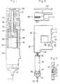
- Fig. 1 einen Achsenlängsschnitt durch ein tragbares Infusionsgerät mit eingesetzter Spritzampulle,
- Fig. 2 einen Querschnitt nach der Linie 11-11 in Fig. 1 in grösserem Massstab,
- Fig. 3 einen Querschnitt nach der Linie 111-111 in Fig. 1,
- Fig. 4 einen Achsenlängsschnitt durch eine Variante des Infusionsgeräts nach Fig. 1,
- Fig. 5 eine aufgegliederte Darstellung des Infusionsgeräts nach Fig. 4, in kleinerem Massstab, und
- Fig. 6 einen Schnitt nach der Linie VI-VI in Fig. 5, in grösserem Massstab.
- 1 shows an axial longitudinal section through a portable infusion device with an inserted injection ampoule,
- 2 shows a cross section along the line 11-11 in Fig. 1 on a larger scale,
- 3 shows a cross section along the line 111-111 in FIG. 1,
- 4 shows an axial longitudinal section through a variant of the infusion device according to FIG. 1,
- Fig. 5 is a broken down representation of the infusion device of FIG. 4, on a smaller scale, and
- Fig. 6 is a section along the line VI-VI in Fig. 5, on a larger scale.
Das in Fig. 1 bis 3 dargestellte Gerät hat ein Gehäuse 1, in dem eine Antriebsvorrichtung angeordnet ist. Die (nicht dargestellte) Antriebsvorrichtung hat einen von einer Batterie gespeisten und durch eine Steuervorrichtung gesteuerten Schrittmotor, der ein Ritzel 2 antreibt. Die Steuervorrichtung kann die Taktfrequenz der den Schrittmotor steuernden Steuerimpulse im Tagesablauf nach einer vom Arzt festgelegten Funktion der Uhrzeit einstellen und dazu eine Uhr und einen Speicher aufweisen, in dem für bestimmte Uhrzeiten, z. B. jede Stunde des Tages, bestimmte, vom Arzt festgelegte Infusionsraten als Steuerwerte gespeichert sind.The device shown in FIGS. 1 to 3 has a housing 1 in which a drive device is arranged. The drive device (not shown) has a stepper motor which is powered by a battery and controlled by a control device and which drives a pinion 2. The control device can set the clock frequency of the control pulses controlling the stepper motor in the course of the day according to a function of the time defined by the doctor and for this purpose have a clock and a memory in which for certain times, e.g. B. every hour of the day, certain infusion rates set by the doctor are stored as control values.
Der hintere (in der Zeichnung obere) Teil 3 des Gehäuses 1 hat einen zylindrischen Hohlraum 4, der am hinteren Ende geschlossen ist und am vorderen Ende in einen zu ihm koaxialen, zylindrischen Hohlraum 5 des vorderen (in der Zeichnung unteren) Teils 6 des Gehäuses 1 mündet, dessen Hohlraumwand, wie weiter unten näher beschrieben, eine Halterung für eine auswechselbare Spritzampulle und eine Mutter bildet. Im Hohlraum 4 ist eine Mitnehmerhülse 8 drehbar gelagert. auf der ein in das Ritzel 2 greifender Zahnkranz 9 gebildet ist, der in einer ihm angepassten Aussparung des Gehäuseteils 3 läuft, wobei die Wände der Aussparung eine axiale Verschiebung des Zahnkranzes 9 und damit auch der Hülse 8 verhindern. (Um die Hülse 8 mit dem Zahnkranz 9 bei der Herstellung des Geräts einsetzen zu können, wird das Gehäuse 1 aus zwei Stücken zusammengesetzt, zwischen denen die Aussparung gebildet ist, und die nach Einsetzen der Hülse 8 zusammgefügt, z. B. verklebt werden.) In die Mitnehmerhülse 8 ist eine Gewindestange 11 drehfest, aber längsverschiebbar eingesetzt. Für die drehfeste Lagerung ist die Gewindestange 11 an gegenüberliegenden Seiten abgeflacht und die Bohrung der Mitnehmerhülse im Querschnitt entsprechend angepasst. Die Gewindestange 11 hat also zwei ebene, parallele, glatte Längsflächen, an denen sie von den entsprechenden ebenen Innenwandflächen der Hülse 8 mitgenommen wird, und zwei mit dem Gewinde versehene Zylindermanteisegmente, die einen Abstand von den beiden glatten, zylindrischen Innenwandflächen der Hülse 8 haben. Am vorderen (in der Zeichnung unteren) Ende der Gewindestange 11 ist eine mit einem koaxial zur Gewindestange 11 vorstehenden, gewindelosen Zapfen 13, der in das für die Aufnahme einer Kolbenstange vorgesehene Sackloch des Kolbens 14 einer Spritzampulle 15 einführbar ist, gebildete Scheibe 17 drehbar gelagert. Der Durchmesser der Scheibe 17 ist kleiner als der Durchmesser des Kolbens 14, so dass die Scheibe auf dem Kolben 14 aufliegend in das Ampullenrohr einführbar ist. Auf den an die Scheibe 17 angrenzenden, in der Zeichnung unteren Teil der Gewindestange 11 ist eine mit einer Aussenverzahnung 20 versehene Mutter 21 geschraubt. Beim weiter unten beschriebenen Einsetzen der Gewindestange 11 in die Hülse 8 wird die Aussenverzahnung 20 der Mutter 21 in Eingriff gebracht mit einer entsprechenden Innenverzahnung 22 an der an die hintere Stirnwand 23 des zylindrischen Hohlraums 5 angrenzenden Mantelfläche der Innenwand des Gehäuseteils 6. Die Dicke der Mutter 21 ist grösser als die Zahnbreite der Innenverzahnung 22, und der Durchmesser des Kopfkreises der Aussenverzahnung 20 entspricht etwa dem Aussendurchmesser der Spritzampulle 15, so dass die Mutter 21 nach dem weiter unten beschriebenen Einsetzen der Spritzampulle 15 zwischen deren hinterem Ende und der hinteren Stirnwand 23 des Hohlraums 5 gegen axiale Verschiebung gesichert eingeklemmt ist. Das freie, vordere (in der Zeichnung untere) Ende 24 des Gehäuseteils 6 ist mit einem Innengewinde versehen, in das ein mit einem Aussengewinde 26 versehener Anschlussteil 27 geschraubt ist. Dieser hat einen zylindrischen Hohlraum für die Aufnahme der Aluminiumkappe 29 der Spritzampulle 15 und einen konischen Hohlraum für die Aufnahme des aus Kunststoff bestehenden Auslassstücks 30 der Spritzampulle 15, des sogenannten Luers. Beim Anschrauben des Anschlussteiles 27 wird der Luer 30 dicht an die Wandung des konischen Hohlraums gedrückt. In das vordere Ende des Anschlussteiles 27 ist ein mit dem konischen Hohlraum kommunizierender durch ein biegsames Röhrchen gebildeter Katheter 32 geschweisst, der bei dicht an den konischen Hohlraumwänden anliegendem Luer 30 an dessen Austrittsöffnung angrenzt oder einen kleinen Abstand von ihr hat.The rear (in the drawing upper)
Für das Gerät können handelsübliche Spritzampullen verwendet werden. Die in der Zeichnung dargestellte Spritzampulle 15 ist eine solche handelsübliche Spritzampulle, deren Kolben 14 ein Gewindesackloch für eine Kolbenstange hat. Bevorzugt werden bereits z. B. mit Insulin gefüllte Spritzampullen verwendet, die ohne Kolbenstange geliefert werden. Der Patient kann aber auch leere Spritzampullen verwenden, die mit einer in das Gewindesackloch schraubbaren handelsüblichen Kolbenstange geliefert werden. Nach dem Füllen der Spritzampulle hat der Patient dann lediglich die Kolbenstange aus dem Gewindesackloch herauszuschrauben.Commercially available spray ampoules can be used for the device. The
Die gefüllte Spritzampulle 15 wird mit ihrem Luer 30 - nach Entfernen einer diesen verschliessenden Schutzkappe - in den Anschlussteil 27 gesteckt. Danach wird die Gewindestange 11, auf weicher die Mutter 21 anliegend an der Scheibe 17 sitzt, mit dem drehbar an ihr gelagerten Zapfen 13 in das Sackloch des Kolbens 14 gesteckt, so dass die Scheibe 17 am Kolben 14 anliegt. Nun wird die Spritzampulle 15 mit Hilfe des griffigen Anschlussteils 27 in den Hohlraum 5 eingeführt und nach hinten geschoben, wobei sie durch die zylindrische Hohlraumwandung geführt und die Gewindestange 11 koaxial an die Mitnehmerhülse 8 heran und in diese hinein geführt wird. Beim weiteren Vorschieben greift die Aussenverzahnung 20 der Mutter 21 in die Innenverzahnung 22. (Um das Einführen der Gewindestange 11 in die Mitnehmerhülse 8 zu erleichtern, kann das hintere Ende der Gewindestange verjüngt sein. Entsprechend kann die Aussenverzahnung 20 der Mutter 21 an der in die Innenverzahnung 22 einzuführenden Stirnseite abgeschrägt sein.) Schliesslich wird der Anschlussteil 27 mit seinem Gewinde 26 in das Gehäuseende 24 geschraubt. Beim Anschrauben drückt die an der Stirnwand 23 des Hohlraums 5 abgestützte Mutter 21 die über das Spritzampullenende vorstehende Scheibe 17 und damit auch den bündig im hinteren Ende der Spritzampulle sitzenden Kolben 14 nach vorne. so dass die Flüssigkeit aus der Spritzampulle 15 in den mit dem Luer 30 kommunizierenden Katheter 32 austritt. Die für den Vorschub des Kolbens 14 beim Anschrauben des Anschlussteils 27 massgebenden Abmessungen (Länge des Hohlraums 5, der Hohlräume im Anschlussteil 27, des Gewindes 26 usw.) sind so gewählt, dass die Flüssigkeit mit Sicherheit den Katheter bis hin zur Spitze der an ihn angeschlossenen Nadel füllt, d. h. eine geringe Flüssigkeitsmenge aus der Nadel austritt. Nach dem Anschrauben des Anschlussteils 27 liegt der hintere Rand des Hohlzylinders der Spritzampulle 15 an der Mutter 21 an, sodass die Mutter zwischen dem hinteren Spritzampullenrand und der Stirnwand 23 gegen axiale Verschiebung gesichert ist.The filled
Das nun betriebsbereite Gerät arbeitet wie folgt : Der durch die Steuervorrichtung gesteuerte Motor treibt über das Ritzel 2 den an der Mitnehmerhülse 8 gebildeten Zahnkranz 9 an. Die Mitnehmerhülse 8 nimmt bei ihrer Drehung die Gewindestange 11 mit, die sich unter Vorschub des Kolbens 14 als Schraubenspindel durch die von der Verzahnung 22 drehfest im Gehäuse gehaltene Mutter 21 nach vorne schraubt.The now operational device works as follows: The motor controlled by the control device drives the
Die drehbare Lagerung von Scheibe 17 und Zapfen 13 an der Gewindestange 11 hat gegenüber einer grundsätzlich selbstverständlich auch möglichen, festen Lagerung den Vorteil, dass keine Reibung am Kolben auftritt und deshalb der Stromverbrauch des Antriebsmotors klein gehalten wird. Es hat sich überraschenderweise gezeigt, dass diese drehbare Lagerung das Einführen der Gewindestange 11 in die Mitnehmerhülse 8 (und der Mutterverzahnung 20 in die Innenverzahnung 22) nicht erschwert sondern im Gegenteil gegenüber einer festen Lagerung eher erleichtert. Bei einer festen Lagerung ist der Anschlussteil 27 mit der Spritzampulle 15 beim Einführen so zu drehen, dass die Gewindestange 11 in die richtige Lage für die Einführung in die Mitnehmerhülse 8 gelangt. Bei der drehbaren Lagerung genügt eine leichte Rüttelbewegung, damit die Gewindestange 11 in die Mitnehmerhülse 8 hineinrutscht.The rotatable mounting of the
Die in Fig. 4-6 dargestellte Variante des Geräts ist im Prinzip gleich aufgebaut wie das Gerät von Fig. 1-3. Im folgenden werden deshalb im wesentlichen nur die Teile der Variante näher erläutert, die sich von den Teilen des Geräts gemäss Fig. 1-3 unterscheiden. Dabei sind die Teile der Variante, welche den im Zusammenhang mit Fig. 1-3 erwähnten Teilen 1, 2, 3, ..., in ihrer Funktion entsprechen, in Fig. 4-6, soweit sie mit Bezugszahlen versehen sind, mit 101, 102, 103, ..., bezeichnet.The variant of the device shown in Fig. 4-6 is basically the same as the device of Fig. 1-3. Therefore, only the parts of the variant which differ from the parts of the device according to FIGS. 1-3 are essentially explained in more detail below. The parts of the variant which correspond in their function to
Das Gehäuse 101 der dargestellten Variante hat eine als Halterung für die Spritzampulle 115 dienende, hohlzylindrische Kammer 105. Die Kammerwandung ist gebildet durch den vorderen (in der Zeichnung unteren) Teil der linken, halbzylindrischen Seitenwand 106 des Gehäuses 101, eine halbzylindrische Trennwand 107 und einen zylindrischen, mit einem Innengewinde versehenen Gehäuseansatz 124. Die Trennwand 107 erstreckt sich vom Gehäuseansatz 124 zu einer die Kammer 105 hinten (in der Zeichnung oben) begrenzenden Stirnwand 123, die ein der Mitnehmerhülse 108 angepasstes Loch aufweist und an der die Mutter 121 abgestützt wird. Die an die Stirnwand 123 angrenzende Mantelfläche der zylindrischen Kammerwandung weist die Innenverzahnung 122 auf. Vorne (in der Zeichnung unten) ist die Kammer 105 durch einen in den Gehäuseansatz 124 schraubbaren Anschlussteil 127 abschliessbar, an den ein Katheter 132 fest angeschlossen ist, der am anderen Ende einen (nicht dargestellten) zweiten Anschlussteil für die Nadel hat. Der zweite Anschlussteil ist ebenfalls fest mit dem Katheter verbunden, z. B. verschweisst, und mit einem Gewinde versehen, in das ein fest mit einer Nadel verbundener Gewindestutzen schraubbar ist. Damit ist eine gegen Zug gesicherte Verbindung von der Nadel über den Katheter bis zum Anschlussstück der Spritzampulle gewährleistet. Am Gewindestutzen 126 des Anschlussteils 127 ist ein 0-Ring 128 vorgesehen, damit eine wasserdichte Verbindung des Anschlussteils 127 mit dem Gehäuseansatz 124 sichergestellt ist.The
Im Raum zwischen der Trennwand 107 und der rechten Seitenwand 134 des Gehäuses 101 ist eine (nicht dargestellte) Steuervorrichtung für die Antriebsvorrichtung angeordnet. Die Steuervorrichtung hat zwei Schaltkontakte, die durch Druck auf zwei an der rechten Seitenwand 134 angeordnete Knöpfe 135 betätigbar sind (Fig. 6). Die Knöpfe bestehen aus elastischem Material und haben einen Kragen 136, der mittels eines Rings 137 an den Rand des Durchgangslochs für die Betätigung des Schaltkontakts gedrückt ist, so dass das Loch wasserdicht abgeschlossen ist. Durch ein in die Gehäusewand eingefügtes Fenster 138 ist eine Anzeige der Steuervorrichtung ablesbar.A control device (not shown) for the drive device is arranged in the space between the
Zum Einbau der Steuervorrichtung und einer die Mitnehmehülse 108 und die Antriebsvorrichtung aufweisenden Baueinheit 139 ist das Gehäuse 101 an der hinteren (in der Zeichnung oberen) Seite offen, wobei die Oeffnung nach dem Einbau durch einen Deckel 140 dicht verschlossen wird. Die Baueinheit 139 hat einen Träger 141, an dem die Mitnehmerhülse 108 drehbar gelagert ist, und der einen Schrittmotor 142 sowie ein Getriebe mit einem den Zahnkranz 109 der Mitnehmerhülse 108 antreibenden Ritzel trägt. Die in das Gehäuse 101 eingesetzte Baueinheit 139 ist zwischen der Stirnwand 123 sowie einem Gehäuseansatz 143 und dem Deckel 140 gehalten, wobei die Mitnehmerhülse 108 in das Loch der Stirnwand 123 und ein Sackloch im Deckel 140 hineinragt. Zur Speisung des Schrittmotors 142 und der Steuervorrichtung sind zwei separate (nicht dargestellte) Batterien vorgesehen, die in zwei durch Schraubverschlüsse dicht verschliessbaren, kleinen Kammern im vorderen (in Fig. 5 unteren) Teil des Gehäuses 101 zwischen der Kammer 105 und der rechten Seitenwand 134 angeordnet sind.For the installation of the control device and a
Durch die Erfindung wird ein zuverlässiges Vorschieben des Kolbens auch bei geringem Drehmoment der Antriebsvorrichtung (z. B. infolge nachlassender Batteriespannung) sichergestellt, wobei nur die für den Kolbenvorschub erforderliche axiale Kraft und keine radialen Kräfte auf die die Kolbenstange bildende Gewindestange wirkt : Die erfindungsgemässe Lösung ermöglicht es, die ganze Spritzampulle mit ihrem Anschlussstück sicher und geschützt im Gehäuse zu haltern. Dabei kann das Gehäuse sämtliche Teile des Geräts umschliessen und wasserdicht ausgeführt werden, so dass der Patient gefahrlos duschen oder sogar baden kann.The invention ensures reliable advancement of the piston even with low torque of the drive device (e.g. as a result of decreasing battery voltage), only the axial force required for the piston advance acting and no radial forces acting on the threaded rod forming the piston rod: the solution according to the invention makes it possible to hold the entire spray ampoule with its connector securely and protected in the housing. The housing can enclose all parts of the device and be made watertight, so that the patient can shower or even bathe safely.
Durch die feste Verbindung des Katheters 32 mit dem Anschlussteil 27 wird die Gefahr vermieden, dass der Patient. z. B. im Schlaf, den Katheter wegreisst. Das erfindungsgemässe Gerät braucht nur gerade so lang bemessen zu werden, wie dies durch die Spritzampulle und die erforderliche Kolbenstangenlänge bedingt ist.Through the fixed connection of the
Claims (10)
Applications Claiming Priority (2)
| Application Number | Priority Date | Filing Date | Title |
|---|---|---|---|
| CH4887/83 | 1983-09-07 | ||
| CH488783 | 1983-09-07 |
Publications (2)
| Publication Number | Publication Date |
|---|---|
| EP0143895A1 EP0143895A1 (en) | 1985-06-12 |
| EP0143895B1true EP0143895B1 (en) | 1987-12-23 |
Family
ID=4284274
Family Applications (1)
| Application Number | Title | Priority Date | Filing Date |
|---|---|---|---|
| EP84109715AExpiredEP0143895B1 (en) | 1983-09-07 | 1984-08-16 | Portable infusion apparatus |
Country Status (4)
| Country | Link |
|---|---|
| US (1) | US4585439A (en) |
| EP (1) | EP0143895B1 (en) |
| JP (1) | JPS6072562A (en) |
| DE (1) | DE3468173D1 (en) |
Cited By (4)
| Publication number | Priority date | Publication date | Assignee | Title |
|---|---|---|---|---|
| US6500239B2 (en) | 2001-03-14 | 2002-12-31 | Penjet Corporation | System and method for removing dissolved gas from a solution |
| US6613010B2 (en) | 2001-04-13 | 2003-09-02 | Penjet Corporation | Modular gas-pressured needle-less injector |
| US6755220B2 (en) | 2001-04-27 | 2004-06-29 | Penjet Corporation | Method and apparatus for filling or refilling a needle-less injector |
| US7018356B2 (en) | 2002-10-31 | 2006-03-28 | Wise Roger R | Method and apparatus for adjusting the contents of a needle-less injector |
Families Citing this family (216)
| Publication number | Priority date | Publication date | Assignee | Title |
|---|---|---|---|---|
| DE3606163A1 (en)* | 1986-02-26 | 1987-08-27 | Hoechst Ag | DEVICE FOR APPLICATING MEDICAL SUSPENSIONS |
| US4719825A (en)* | 1986-03-24 | 1988-01-19 | Lahaye Peter G | Metering needle assembly |
| GB8713810D0 (en)* | 1987-06-12 | 1987-07-15 | Hypoguard Uk Ltd | Measured dose dispensing device |
| US4973318A (en)* | 1988-02-10 | 1990-11-27 | D.C.P. Af 1988 A/S | Disposable syringe |
| DE3833821A1 (en)* | 1988-10-05 | 1990-04-12 | Braun Melsungen Ag | INJECTION DEVICE |
| US5300031A (en) | 1991-06-07 | 1994-04-05 | Liebel-Flarsheim Company | Apparatus for injecting fluid into animals and disposable front loadable syringe therefor |
| US5300042A (en)* | 1992-03-02 | 1994-04-05 | Kossoff-Sukel, Inc. | Medication dispensing apparatus |
| US5273537A (en)* | 1992-03-06 | 1993-12-28 | Scimed Life Systems, Inc. | Power-assisted inflation apparatus |
| US6402718B1 (en) | 1992-08-17 | 2002-06-11 | Medrad, Inc. | Front-loading medical injector and syringe for use therewith |
| US5383858B1 (en) | 1992-08-17 | 1996-10-29 | Medrad Inc | Front-loading medical injector and syringe for use therewith |
| CH685461B5 (en)* | 1993-01-05 | 1996-01-31 | Jean Claude Berney | liquid substances therapeutic infusion sets and portable device comprising such a device. |
| US5472022A (en)* | 1993-11-02 | 1995-12-05 | Genentech, Inc. | Injection pen solution transfer apparatus and method |
| US5514097A (en)* | 1994-02-14 | 1996-05-07 | Genentech, Inc. | Self administered injection pen apparatus and method |
| US5536249A (en)* | 1994-03-09 | 1996-07-16 | Visionary Medical Products, Inc. | Pen-type injector with a microprocessor and blood characteristic monitor |
| NZ304285A (en)* | 1995-03-14 | 1998-12-23 | Siemens Ag | Ultrasonic atomizer device with a removable precision dosing unit |
| ZA962078B (en)* | 1995-03-14 | 1996-09-25 | Siemens Ag | Ultrasonic atomizer device with removable precision dosating unit |
| AU1860697A (en)* | 1995-09-08 | 1997-07-28 | Visionary Medical Products Corporation | Pen-type injector drive mechanism |
| JP2000513967A (en)* | 1996-07-01 | 2000-10-24 | フアーマシア・アンド・アツプジヨン・アー・ベー | Distributing apparatus and operating method thereof |
| CN1176727C (en)* | 1996-07-01 | 2004-11-24 | 法玛西雅和厄普约翰公司 | Injection device |
| US6413242B1 (en) | 1996-07-05 | 2002-07-02 | Disetronic Licensing Ag | Injection device for injection of liquid |
| US6558900B2 (en)* | 1996-07-12 | 2003-05-06 | Emory University | Regulation of apoptosis and in vitro model for studies thereof |
| DE19723648C1 (en) | 1997-06-05 | 1998-08-27 | Disetronic Licensing Ag | Controlled infusion equipment with leak and reverse flow prevention used e.g. in insulin therapy |
| US6171276B1 (en) | 1997-08-06 | 2001-01-09 | Pharmacia & Upjohn Ab | Automated delivery device and method for its operation |
| US5893838A (en)* | 1997-08-15 | 1999-04-13 | Therox, Inc. | System and method for high pressure delivery of gas-supersaturated fluids |
| CH692543A5 (en) | 1997-09-25 | 2002-07-31 | Disetronic Licensing Ag | Dispenser with auto switch. |
| CZ297361B6 (en) | 1998-01-30 | 2006-11-15 | Novo Nordisk A/S | Injection syringe |
| US5919167A (en)* | 1998-04-08 | 1999-07-06 | Ferring Pharmaceuticals | Disposable micropump |
| US6949084B2 (en)* | 1998-05-14 | 2005-09-27 | Disetronic Licensing Ag | Catheter head for subcutaneous administration of an active substance |
| DE19821723C2 (en) | 1998-05-14 | 2000-07-06 | Disetronic Licensing Ag | Catheter head for subcutaneous administration of an active ingredient |
| EP0980687B1 (en)* | 1998-08-20 | 2004-03-03 | Sooil Development Co., Ltd. | Portable automatic syringe device |
| DE19840992A1 (en) | 1998-09-08 | 2000-03-09 | Disetronic Licensing Ag | Pressure monitoring of a product fluid to be administered in doses during an infusion or injection |
| CA2345439C (en) | 1998-10-29 | 2005-08-09 | Minimed, Inc. | Compact pump drive system |
| US20020173748A1 (en)* | 1998-10-29 | 2002-11-21 | Mcconnell Susan | Reservoir connector |
| US6800071B1 (en)* | 1998-10-29 | 2004-10-05 | Medtronic Minimed, Inc. | Fluid reservoir piston |
| US6164921A (en) | 1998-11-09 | 2000-12-26 | Moubayed; Ahmad Maher | Curvilinear peristaltic pump having insertable tubing assembly |
| DE29915878U1 (en) | 1999-09-09 | 2000-10-26 | Disetronic Licensing Ag, Burgdorf | Device for decanting medicinal products and cannula arrangement |
| TW453884B (en) | 1999-09-16 | 2001-09-11 | Novo Nordisk As | Dose setting limiter |
| US7063684B2 (en)* | 1999-10-28 | 2006-06-20 | Medtronic Minimed, Inc. | Drive system seal |
| US6958053B1 (en)* | 1999-11-24 | 2005-10-25 | Medrad, Inc. | Injector providing drive member advancement and engagement with syringe plunger, and method of connecting a syringe to an injector |
| US6652489B2 (en)* | 2000-02-07 | 2003-11-25 | Medrad, Inc. | Front-loading medical injector and syringes, syringe interfaces, syringe adapters and syringe plungers for use therewith |
| US6485461B1 (en) | 2000-04-04 | 2002-11-26 | Insulet, Inc. | Disposable infusion device |
| AU6179001A (en)* | 2000-05-18 | 2001-11-26 | Dentsply Int Inc | Fluid material dispensing syringe |
| US6663602B2 (en)* | 2000-06-16 | 2003-12-16 | Novo Nordisk A/S | Injection device |
| AUPQ867900A0 (en) | 2000-07-10 | 2000-08-03 | Medrad, Inc. | Medical injector system |
| CA2421133C (en) | 2000-09-08 | 2012-06-26 | Insulet Corporation | Devices, systems and methods for patient infusion |
| US6669669B2 (en)* | 2001-10-12 | 2003-12-30 | Insulet Corporation | Laminated patient infusion device |
| US20050273079A1 (en)* | 2000-10-10 | 2005-12-08 | Hohlfelder Ingrid E | Fluid material dispensing syringe |
| ES2281457T3 (en) | 2000-11-09 | 2007-10-01 | Insulet Corporation | TRANSCUTANEOUS SUPPLY MEDIA. |
| AU2002239709B2 (en) | 2000-12-21 | 2007-02-15 | Insulet Corporation | Medical apparatus remote control and method |
| US6758837B2 (en) | 2001-02-08 | 2004-07-06 | Pharmacia Ab | Liquid delivery device and method of use thereof |
| US6673049B2 (en) | 2001-02-15 | 2004-01-06 | Disetronic Licensing Ag | Injection device for injecting fluid |
| EP1381408A4 (en) | 2001-02-22 | 2007-06-13 | Insulet Corp | Modular infusion device and method |
| US6699234B2 (en) | 2001-03-16 | 2004-03-02 | Show-Way Yeh | Light, thin, and flexible medication infusion apparatuses attachable to user's skin |
| CA2457943A1 (en)* | 2001-08-31 | 2003-03-06 | Novo-Nordisk A/S | A cartridge for liquid insulin |
| US20040078028A1 (en)* | 2001-11-09 | 2004-04-22 | Flaherty J. Christopher | Plunger assembly for patient infusion device |
| GB0201689D0 (en) | 2002-01-25 | 2002-03-13 | Dca Design Consultants Ltd | Improvements in and relating to a medicament injection device |
| US7041082B2 (en)* | 2002-02-28 | 2006-05-09 | Smiths Medical Md, Inc. | Syringe pump control systems and methods |
| US7033338B2 (en)* | 2002-02-28 | 2006-04-25 | Smiths Medical Md, Inc. | Cartridge and rod for axially loading medication pump |
| US20030163089A1 (en)* | 2002-02-28 | 2003-08-28 | Bynum Gail Beth | Child safety cap for syringe pump |
| US6692457B2 (en) | 2002-03-01 | 2004-02-17 | Insulet Corporation | Flow condition sensor assembly for patient infusion device |
| US6830558B2 (en) | 2002-03-01 | 2004-12-14 | Insulet Corporation | Flow condition sensor assembly for patient infusion device |
| JP4350525B2 (en)* | 2002-03-18 | 2009-10-21 | イーライ リリー アンド カンパニー | Drug dispensing device with gear set giving mechanical advantages |
| US20040153032A1 (en)* | 2002-04-23 | 2004-08-05 | Garribotto John T. | Dispenser for patient infusion device |
| US6960192B1 (en) | 2002-04-23 | 2005-11-01 | Insulet Corporation | Transcutaneous fluid delivery system |
| US6656158B2 (en) | 2002-04-23 | 2003-12-02 | Insulet Corporation | Dispenser for patient infusion device |
| US6656159B2 (en) | 2002-04-23 | 2003-12-02 | Insulet Corporation | Dispenser for patient infusion device |
| US20050238507A1 (en)* | 2002-04-23 | 2005-10-27 | Insulet Corporation | Fluid delivery device |
| JP3854190B2 (en)* | 2002-04-26 | 2006-12-06 | 株式会社ジェイテクト | Motor control device |
| US7553294B2 (en)* | 2002-05-30 | 2009-06-30 | Medrad, Inc. | Syringe plunger sensing mechanism for a medical injector |
| US6723072B2 (en) | 2002-06-06 | 2004-04-20 | Insulet Corporation | Plunger assembly for patient infusion device |
| US7018360B2 (en) | 2002-07-16 | 2006-03-28 | Insulet Corporation | Flow restriction system and method for patient infusion device |
| US20040176720A1 (en)* | 2002-08-31 | 2004-09-09 | Urs Kipfer | Device for administering a liquid solution of an active substance |
| US7128727B2 (en)* | 2002-09-30 | 2006-10-31 | Flaherty J Christopher | Components and methods for patient infusion device |
| US7144384B2 (en)* | 2002-09-30 | 2006-12-05 | Insulet Corporation | Dispenser components and methods for patient infusion device |
| US20040116866A1 (en)* | 2002-12-17 | 2004-06-17 | William Gorman | Skin attachment apparatus and method for patient infusion device |
| EP2210634A1 (en)* | 2009-01-22 | 2010-07-28 | Sanofi-Aventis Deutschland GmbH | Drug delivery device dose setting mechanism |
| GB0304822D0 (en) | 2003-03-03 | 2003-04-09 | Dca Internat Ltd | Improvements in and relating to a pen-type injector |
| GB0308267D0 (en)* | 2003-04-10 | 2003-05-14 | Dca Design Int Ltd | Improvements in and relating to a pen-type injector |
| US20050182366A1 (en)* | 2003-04-18 | 2005-08-18 | Insulet Corporation | Method For Visual Output Verification |
| US7419478B1 (en) | 2003-06-25 | 2008-09-02 | Medrad, Inc. | Front-loading syringe for medical injector having a flexible syringe retaining ring |
| CA2530263C (en) | 2003-08-12 | 2012-04-17 | Eli Lilly And Company | Medication dispensing apparatus with triple screw threads for mechanical advantage |
| US8422413B2 (en)* | 2003-09-18 | 2013-04-16 | Dentsply International Inc. | Process and device for the wireless transmission of dental process data |
| US20050065760A1 (en)* | 2003-09-23 | 2005-03-24 | Robert Murtfeldt | Method for advising patients concerning doses of insulin |
| US20050070847A1 (en)* | 2003-09-29 | 2005-03-31 | Van Erp Wilhelmus Petrus Martinus Maria | Rapid-exchange balloon catheter with hypotube shaft |
| USD1031029S1 (en) | 2003-11-25 | 2024-06-11 | Bayer Healthcare Llc | Syringe plunger |
| US7666169B2 (en) | 2003-11-25 | 2010-02-23 | Medrad, Inc. | Syringe and syringe plungers for use with medical injectors |
| DK1732628T3 (en)* | 2004-03-30 | 2011-10-24 | Lilly Co Eli | Medication dispenser with gear set with opening for a drive element |
| EP1732629B1 (en)* | 2004-03-30 | 2019-04-24 | Eli Lilly And Company | Medication dispensing apparatus with spring-driven locking feature enabled by administration of final dose |
| US8177760B2 (en)* | 2004-05-12 | 2012-05-15 | C. R. Bard, Inc. | Valved connector |
| ATE444090T1 (en) | 2004-10-21 | 2009-10-15 | Novo Nordisk As | SELECTION MECHANISM FOR A ROTARY PIN |
| DE102004059126B4 (en)* | 2004-12-08 | 2014-01-16 | Roche Diagnostics Gmbh | Adapter for injection device |
| US20060173439A1 (en)* | 2005-01-18 | 2006-08-03 | Thorne Gale H Jr | Syringe drive system |
| US20060178633A1 (en)* | 2005-02-03 | 2006-08-10 | Insulet Corporation | Chassis for fluid delivery device |
| WO2006089768A1 (en)* | 2005-02-28 | 2006-08-31 | Novo Nordisk A/S | A dose setting mechanism for an injection device |
| US20090043264A1 (en)* | 2005-04-24 | 2009-02-12 | Novo Nordisk A/S | Injection Device |
| US7552240B2 (en)* | 2005-05-23 | 2009-06-23 | International Business Machines Corporation | Method for user space operations for direct I/O between an application instance and an I/O adapter |
| JP5062768B2 (en) | 2006-03-10 | 2012-10-31 | ノボ・ノルデイスク・エー/エス | INJECTION DEVICE AND METHOD FOR REPLACING CARTRIDGE OF THE DEVICE |
| CN101400394B (en) | 2006-03-10 | 2012-07-04 | 诺沃-诺迪斯克有限公司 | An injection device having a gearing arrangement |
| US8926569B2 (en) | 2006-03-15 | 2015-01-06 | Bayer Medical Care Inc. | Plunger covers and plungers for use in syringes and methods of fabricating plunger covers and plungers for use in syringes |
| ATE458517T1 (en) | 2006-05-16 | 2010-03-15 | Novo Nordisk As | TRANSMISSION MECHANISM FOR AN INJECTION DEVICE |
| JP5253387B2 (en)* | 2006-05-18 | 2013-07-31 | ノボ・ノルデイスク・エー/エス | Injection device with mode locking means |
| EP2109474B2 (en) | 2007-02-05 | 2019-01-30 | Novo Nordisk A/S | Injection button |
| USD942005S1 (en) | 2007-03-14 | 2022-01-25 | Bayer Healthcare Llc | Orange syringe plunger cover |
| USD847985S1 (en) | 2007-03-14 | 2019-05-07 | Bayer Healthcare Llc | Syringe plunger cover |
| USD1002840S1 (en) | 2007-03-14 | 2023-10-24 | Bayer Healthcare Llc | Syringe plunger |
| BRPI0809265A2 (en)* | 2007-03-23 | 2014-10-07 | Novo Nordisk As | INJECTION DEVICE INCLUDING A TIGHTENING NUT |
| US20080281289A1 (en)* | 2007-05-08 | 2008-11-13 | Lewis Michael I | Unit dose dry powder ejection carpule |
| US7967795B1 (en) | 2010-01-19 | 2011-06-28 | Lamodel Ltd. | Cartridge interface assembly with driving plunger |
| US10420880B2 (en) | 2007-10-02 | 2019-09-24 | West Pharma. Services IL, Ltd. | Key for securing components of a drug delivery system during assembly and/or transport and methods of using same |
| US9656019B2 (en) | 2007-10-02 | 2017-05-23 | Medimop Medical Projects Ltd. | Apparatuses for securing components of a drug delivery system during transport and methods of using same |
| BRPI0817907B8 (en) | 2007-10-02 | 2021-06-22 | Lamodel Ltd | apparatus for administering a substance to an individual |
| US9345836B2 (en) | 2007-10-02 | 2016-05-24 | Medimop Medical Projects Ltd. | Disengagement resistant telescoping assembly and unidirectional method of assembly for such |
| CA3070618C (en) | 2008-05-20 | 2021-07-20 | Avant Medical Corp. | Autoinjector system |
| US8052645B2 (en) | 2008-07-23 | 2011-11-08 | Avant Medical Corp. | System and method for an injection using a syringe needle |
| US7959598B2 (en) | 2008-08-20 | 2011-06-14 | Asante Solutions, Inc. | Infusion pump systems and methods |
| US9393369B2 (en) | 2008-09-15 | 2016-07-19 | Medimop Medical Projects Ltd. | Stabilized pen injector |
| US12097357B2 (en) | 2008-09-15 | 2024-09-24 | West Pharma. Services IL, Ltd. | Stabilized pen injector |
| CH700630A1 (en)* | 2009-03-18 | 2010-09-30 | Tecpharma Licensing Ag | Cartridge for application device that is utilized for applying e.g. heparin, to patient, has guiding sleeve arranged so that sleeve is shifted around minimum shifting path in distal direction opposite to housing before starting cartridge |
| WO2011006924A1 (en) | 2009-07-15 | 2011-01-20 | Sanofi-Aventis Deutschland Gmbh | Thrust bearing assembly, drive train, and medicament delivery device |
| US8157769B2 (en) | 2009-09-15 | 2012-04-17 | Medimop Medical Projects Ltd. | Cartridge insertion assembly for drug delivery system |
| US10071196B2 (en) | 2012-05-15 | 2018-09-11 | West Pharma. Services IL, Ltd. | Method for selectively powering a battery-operated drug-delivery device and device therefor |
| US10071198B2 (en) | 2012-11-02 | 2018-09-11 | West Pharma. Servicees IL, Ltd. | Adhesive structure for medical device |
| US8348898B2 (en) | 2010-01-19 | 2013-01-08 | Medimop Medical Projects Ltd. | Automatic needle for drug pump |
| EP2569031B1 (en) | 2010-05-10 | 2017-10-11 | Medimop Medical Projects Ltd. | Low volume accurate injector |
| CN102939120B (en) | 2010-06-04 | 2016-12-07 | 拜耳医药保健有限责任公司 | Systems and methods for planning and monitoring the use of multiple doses of radiopharmaceuticals on radiopharmaceutical syringes |
| USD702834S1 (en) | 2011-03-22 | 2014-04-15 | Medimop Medical Projects Ltd. | Cartridge for use in injection device |
| PL2510914T3 (en)* | 2011-04-12 | 2015-02-27 | Hoffmann La Roche | Connector device |
| PL2699293T3 (en) | 2011-04-20 | 2019-08-30 | Amgen Inc. | Autoinjector apparatus |
| JP6069351B2 (en) | 2011-12-29 | 2017-02-01 | ノボ・ノルデイスク・エー/エス | Torsion spring type automatic syringe with dial-up / dial-down administration mechanism |
| US9072827B2 (en) | 2012-03-26 | 2015-07-07 | Medimop Medical Projects Ltd. | Fail safe point protector for needle safety flap |
| EP4406568A3 (en) | 2012-03-30 | 2024-10-16 | Insulet Corporation | Fluid delivery device with transcutaneous access tool, insertion mechanism and blood glucose monitoring for use therewith |
| USD898908S1 (en) | 2012-04-20 | 2020-10-13 | Amgen Inc. | Pharmaceutical product cassette for an injection device |
| US9174003B2 (en) | 2012-09-28 | 2015-11-03 | Bayer Medical Care Inc. | Quick release plunger |
| US9421323B2 (en) | 2013-01-03 | 2016-08-23 | Medimop Medical Projects Ltd. | Door and doorstop for portable one use drug delivery apparatus |
| CN103083756A (en)* | 2013-01-18 | 2013-05-08 | 郑州瑞宇科技有限公司 | Intelligent insulin pump |
| CA2904661C (en) | 2013-03-15 | 2022-03-15 | Amgen Inc. | Drug cassette, autoinjector, and autoinjector system |
| US9011164B2 (en) | 2013-04-30 | 2015-04-21 | Medimop Medical Projects Ltd. | Clip contact for easy installation of printed circuit board PCB |
| US9561324B2 (en) | 2013-07-19 | 2017-02-07 | Bigfoot Biomedical, Inc. | Infusion pump system and method |
| FI3060276T3 (en) | 2013-10-24 | 2023-06-07 | Infusion system for preventing mischanneling of multiple medicaments | |
| AU2015231396B2 (en) | 2014-03-19 | 2018-12-06 | Bayer Healthcare Llc | System for syringe engagement to an injector |
| US10792418B2 (en) | 2014-10-28 | 2020-10-06 | Bayer Healthcare Llc | Self-orienting pressure jacket and pressure jacket-to-injector interface |
| NO2689315T3 (en) | 2014-10-28 | 2018-04-14 | ||
| WO2016069714A1 (en) | 2014-10-28 | 2016-05-06 | Bayer Healthcare Llc | Self-orienting pressure jacket and pressure jacket-to-injector interface |
| US9199033B1 (en) | 2014-10-28 | 2015-12-01 | Bayer Healthcare Llc | Self-orienting syringe and syringe interface |
| US10293120B2 (en) | 2015-04-10 | 2019-05-21 | West Pharma. Services IL, Ltd. | Redundant injection device status indication |
| US10149943B2 (en) | 2015-05-29 | 2018-12-11 | West Pharma. Services IL, Ltd. | Linear rotation stabilizer for a telescoping syringe stopper driverdriving assembly |
| CN113181477B (en) | 2015-06-04 | 2023-07-14 | 麦迪麦珀医疗工程有限公司 | Cartridge insertion for drug delivery device |
| EP3319662B1 (en) | 2015-07-08 | 2023-09-13 | Trustees of Boston University | Infusion system and components thereof |
| US9987432B2 (en) | 2015-09-22 | 2018-06-05 | West Pharma. Services IL, Ltd. | Rotation resistant friction adapter for plunger driver of drug delivery device |
| US10086145B2 (en) | 2015-09-22 | 2018-10-02 | West Pharma Services Il, Ltd. | Rotation resistant friction adapter for plunger driver of drug delivery device |
| US10576207B2 (en) | 2015-10-09 | 2020-03-03 | West Pharma. Services IL, Ltd. | Angled syringe patch injector |
| US11318254B2 (en) | 2015-10-09 | 2022-05-03 | West Pharma. Services IL, Ltd. | Injector needle cap remover |
| US9480797B1 (en) | 2015-10-28 | 2016-11-01 | Bayer Healthcare Llc | System and method for syringe plunger engagement with an injector |
| WO2017083622A1 (en) | 2015-11-13 | 2017-05-18 | Bayer Healthcare Llc | Nested syringe assembly |
| US10716896B2 (en) | 2015-11-24 | 2020-07-21 | Insulet Corporation | Wearable automated medication delivery system |
| US10413665B2 (en) | 2015-11-25 | 2019-09-17 | Insulet Corporation | Wearable medication delivery device |
| EP3374905A1 (en) | 2016-01-13 | 2018-09-19 | Bigfoot Biomedical, Inc. | User interface for diabetes management system |
| HK1256995A1 (en) | 2016-01-14 | 2019-10-11 | Bigfoot Biomedical, Inc. | Occlusion resolution in medication delivery devices, systems, and methods |
| US10806859B2 (en) | 2016-01-14 | 2020-10-20 | Bigfoot Biomedical, Inc. | Adjusting insulin delivery rates |
| JP6885960B2 (en) | 2016-01-21 | 2021-06-16 | ウェスト ファーマ サービシーズ イスラエル リミテッド | Drug delivery device with visual indicators |
| US10646643B2 (en) | 2016-01-21 | 2020-05-12 | West Pharma. Services IL, Ltd. | Needle insertion and retraction mechanism |
| EP3711793B1 (en) | 2016-01-21 | 2021-12-01 | West Pharma Services IL, Ltd. | A method of connecting a cartridge to an automatic injector |
| US11389597B2 (en) | 2016-03-16 | 2022-07-19 | West Pharma. Services IL, Ltd. | Staged telescopic screw assembly having different visual indicators |
| US10376647B2 (en) | 2016-03-18 | 2019-08-13 | West Pharma. Services IL, Ltd. | Anti-rotation mechanism for telescopic screw assembly |
| US12383166B2 (en) | 2016-05-23 | 2025-08-12 | Insulet Corporation | Insulin delivery system and methods with risk-based set points |
| US10363374B2 (en) | 2016-05-26 | 2019-07-30 | Insulet Corporation | Multi-dose drug delivery device |
| CN109310831B (en) | 2016-06-02 | 2021-11-23 | 西医药服务以色列有限公司 | Three position needle retraction |
| US11338090B2 (en) | 2016-08-01 | 2022-05-24 | West Pharma. Services IL, Ltd. | Anti-rotation cartridge pin |
| JP7059251B2 (en) | 2016-08-01 | 2022-04-25 | ウェスト ファーマ サービシーズ イスラエル リミテッド | A spring that prevents the door from closing halfway |
| US10363372B2 (en) | 2016-08-12 | 2019-07-30 | Insulet Corporation | Plunger for drug delivery device |
| EP3730169B1 (en) | 2016-08-14 | 2023-08-02 | Insulet Corporation | Drug delivery device with detection of position of the plunger |
| WO2018067645A1 (en) | 2016-10-07 | 2018-04-12 | Insulet Corporation | Multi-stage delivery system |
| US10780217B2 (en) | 2016-11-10 | 2020-09-22 | Insulet Corporation | Ratchet drive for on body delivery system |
| EP3500161A4 (en) | 2016-12-12 | 2020-01-08 | Bigfoot Biomedical, Inc. | ALARMS AND WARNINGS FOR MEDICINE DELIVERY DEVICES AND RELATED SYSTEMS AND METHODS |
| HUE063479T2 (en) | 2017-01-06 | 2024-01-28 | Bayer Healthcare Llc | Syringe plunger with dynamic seal |
| BR112019013985A2 (en) | 2017-01-06 | 2020-03-03 | Trustees Of Boston University | INFUSION SYSTEM AND COMPONENTS OF THE SAME |
| EP3568859A1 (en) | 2017-01-13 | 2019-11-20 | Bigfoot Biomedical, Inc. | Insulin delivery methods, systems and devices |
| US10881792B2 (en) | 2017-01-13 | 2021-01-05 | Bigfoot Biomedical, Inc. | System and method for adjusting insulin delivery |
| US10500334B2 (en) | 2017-01-13 | 2019-12-10 | Bigfoot Biomedical, Inc. | System and method for adjusting insulin delivery |
| US10758675B2 (en) | 2017-01-13 | 2020-09-01 | Bigfoot Biomedical, Inc. | System and method for adjusting insulin delivery |
| WO2018136699A1 (en) | 2017-01-19 | 2018-07-26 | Insulet Corporation | Cartridge hold-up volume reduction |
| JP6232169B1 (en)* | 2017-02-08 | 2017-11-15 | 株式会社根本杏林堂 | Injection device, actuator, and manufacturing method of injection device |
| WO2018156548A1 (en) | 2017-02-22 | 2018-08-30 | Insulet Corporation | Needle insertion mechanisms for drug containers |
| US10695485B2 (en) | 2017-03-07 | 2020-06-30 | Insulet Corporation | Very high volume user filled drug delivery device |
| EP3630226A1 (en) | 2017-05-30 | 2020-04-08 | West Pharma. Services Il, Ltd. | Modular drive train for wearable injector |
| US10973978B2 (en) | 2017-08-03 | 2021-04-13 | Insulet Corporation | Fluid flow regulation arrangements for drug delivery devices |
| US11280327B2 (en) | 2017-08-03 | 2022-03-22 | Insulet Corporation | Micro piston pump |
| RS65380B1 (en) | 2017-08-24 | 2024-04-30 | Novo Nordisk As | Glp-1 compositions and uses thereof |
| US11786668B2 (en) | 2017-09-25 | 2023-10-17 | Insulet Corporation | Drug delivery devices, systems, and methods with force transfer elements |
| EP3687600B1 (en) | 2017-09-26 | 2022-04-27 | Insulet Corporation | Needle mechanism module for drug delivery device |
| EP3473281B1 (en) | 2017-10-17 | 2022-01-05 | Roche Diabetes Care GmbH | A filling aid and methods for self-filling a cartridge |
| US11147931B2 (en) | 2017-11-17 | 2021-10-19 | Insulet Corporation | Drug delivery device with air and backflow elimination |
| JP7402799B2 (en) | 2017-12-22 | 2023-12-21 | ウェスト ファーマ サービシーズ イスラエル リミテッド | Syringes available with different cartridge sizes |
| US11191893B2 (en) | 2018-01-31 | 2021-12-07 | Bayer Healthcare Llc | System and method for syringe engagement with injector |
| HUE061426T2 (en) | 2018-02-27 | 2023-06-28 | Bayer Healthcare Llc | Syringe piston switch mechanism |
| USD928199S1 (en) | 2018-04-02 | 2021-08-17 | Bigfoot Biomedical, Inc. | Medication delivery device with icons |
| US10874803B2 (en) | 2018-05-31 | 2020-12-29 | Insulet Corporation | Drug cartridge with drive system |
| US11229736B2 (en) | 2018-06-06 | 2022-01-25 | Insulet Corporation | Linear shuttle pump for drug delivery |
| US11446435B2 (en) | 2018-11-28 | 2022-09-20 | Insulet Corporation | Drug delivery shuttle pump system and valve assembly |
| USD920343S1 (en) | 2019-01-09 | 2021-05-25 | Bigfoot Biomedical, Inc. | Display screen or portion thereof with graphical user interface associated with insulin delivery |
| CN111973841A (en)* | 2019-05-22 | 2020-11-24 | 上海微创生命科技有限公司 | Infusion device |
| US11364339B2 (en) | 2019-07-11 | 2022-06-21 | Aamir Zain Jamal | Infusion unit |
| CA3146964A1 (en) | 2019-07-16 | 2021-01-21 | Beta Bionics, Inc. | Ambulatory device and components thereof |
| US11957876B2 (en) | 2019-07-16 | 2024-04-16 | Beta Bionics, Inc. | Glucose control system with automated backup therapy protocol generation |
| EP4000075A4 (en) | 2019-07-16 | 2023-10-04 | Beta Bionics, Inc. | BLOOD GLUCOSE CONTROL SYSTEM |
| US11369735B2 (en) | 2019-11-05 | 2022-06-28 | Insulet Corporation | Component positioning of a linear shuttle pump |
| US11529466B2 (en) | 2020-01-08 | 2022-12-20 | Beta Bionics, Inc. | Cloud-connected ambulatory pump integration |
| IL294520A (en) | 2020-02-18 | 2022-09-01 | Novo Nordisk As | Pharmaceutical formulations |
| US11278661B2 (en) | 2020-03-10 | 2022-03-22 | Beta Bionics, Inc. | Infusion system and components thereof |
| USD1031975S1 (en) | 2020-03-10 | 2024-06-18 | Beta Bionics, Inc. | Medicament infusion pump device |
| BR112022023788A2 (en) | 2020-06-18 | 2022-12-27 | Bayer Healthcare Llc | SYSTEM AND METHOD OF COUPLING A SYRINGE PLUNGER WITH AN INJECTOR |
| US20220199218A1 (en) | 2020-12-07 | 2022-06-23 | Beta Bionics, Inc. | Ambulatory medicament pump with integrated medicament ordering interface |
| WO2022133218A1 (en) | 2020-12-18 | 2022-06-23 | Insulet Corporation | Adhesive pad with a metallic coil for securing an on-body medical device |
| AU2022205300B2 (en) | 2021-01-08 | 2025-04-17 | Insulet Corporation | Single actuated precision dose intermediate pumping chamber |
| EP4346945A1 (en) | 2021-05-28 | 2024-04-10 | Insulet Corporation | Spring-based status sensors |
| US12097355B2 (en) | 2023-01-06 | 2024-09-24 | Insulet Corporation | Automatically or manually initiated meal bolus delivery with subsequent automatic safety constraint relaxation |
Family Cites Families (12)
| Publication number | Priority date | Publication date | Assignee | Title |
|---|---|---|---|---|
| US2734504A (en)* | 1956-02-14 | Hypodermic injection devices | ||
| US3720211A (en)* | 1971-08-18 | 1973-03-13 | G Kyrias | Automatic injection system |
| US3812843A (en)* | 1973-03-12 | 1974-05-28 | Lear Siegler Inc | Method and apparatus for injecting contrast media into the vascular system |
| US3886938A (en)* | 1973-10-23 | 1975-06-03 | Scala Anthony | Power operated fluid infusion device |
| US4273122A (en)* | 1976-11-12 | 1981-06-16 | Whitney Douglass G | Self contained powered injection system |
| US4196730A (en)* | 1977-08-01 | 1980-04-08 | Wilson Dennis R | Liquid drug dispenser |
| US4202333A (en)* | 1978-11-08 | 1980-05-13 | Minnesota Mining And Manufacturing Company | Fluid dispensing device |
| DE2906830C2 (en)* | 1979-02-22 | 1981-07-16 | B. Braun Melsungen Ag, 3508 Melsungen | Device for continuous infusions |
| US4407659A (en)* | 1980-06-06 | 1983-10-04 | Varian Associates, Inc. | Drive system |
| US4416662A (en)* | 1980-06-13 | 1983-11-22 | The United States Of America As Represented By The Department Of Health And Human Services | Roller infusion apparatus |
| IE52621B1 (en)* | 1981-02-12 | 1988-01-06 | Turner Robert Charles | Dose metering plunger devices for use with syringes |
| GB2094628A (en)* | 1981-03-10 | 1982-09-22 | Ealing The Corp | Infusion apparatus |
- 1984
- 1984-08-16DEDE8484109715Tpatent/DE3468173D1/ennot_activeExpired
- 1984-08-16EPEP84109715Apatent/EP0143895B1/ennot_activeExpired
- 1984-08-31JPJP59180837Apatent/JPS6072562A/enactivePending
- 1984-09-07USUS06/648,051patent/US4585439A/ennot_activeExpired - Lifetime
Cited By (5)
| Publication number | Priority date | Publication date | Assignee | Title |
|---|---|---|---|---|
| US6500239B2 (en) | 2001-03-14 | 2002-12-31 | Penjet Corporation | System and method for removing dissolved gas from a solution |
| US6613010B2 (en) | 2001-04-13 | 2003-09-02 | Penjet Corporation | Modular gas-pressured needle-less injector |
| US6613011B2 (en) | 2001-04-13 | 2003-09-02 | Penjet Corporation | Gas-pressured engine with valve |
| US6755220B2 (en) | 2001-04-27 | 2004-06-29 | Penjet Corporation | Method and apparatus for filling or refilling a needle-less injector |
| US7018356B2 (en) | 2002-10-31 | 2006-03-28 | Wise Roger R | Method and apparatus for adjusting the contents of a needle-less injector |
Also Published As
| Publication number | Publication date |
|---|---|
| JPS6072562A (en) | 1985-04-24 |
| DE3468173D1 (en) | 1988-02-04 |
| US4585439A (en) | 1986-04-29 |
| EP0143895A1 (en) | 1985-06-12 |
Similar Documents
| Publication | Publication Date | Title |
|---|---|---|
| EP0143895B1 (en) | Portable infusion apparatus | |
| DE69822145T2 (en) | Portable, automatic syringe device | |
| DE69926106T2 (en) | Pen needle magazine | |
| EP0245312B1 (en) | Injection instrument | |
| DE4325897C2 (en) | Injection device | |
| DE60211748T2 (en) | LOAD MECHANISM FOR INFUSION PUMP | |
| DE69110737T2 (en) | Infusion pump with dual position syringe holder. | |
| DE60111200T2 (en) | BENDING PISTON ROD | |
| DE3840000C2 (en) | Injection device | |
| DE69923858T2 (en) | COMPACT PUMP DRIVE SYSTEM | |
| EP0581788B1 (en) | Injection device | |
| EP0315656B1 (en) | Infusion apparatus | |
| DE3432152C2 (en) | ||
| DE3486227T2 (en) | Container structure for the interchangeable connection with a motor drive. | |
| DE69621133T2 (en) | AUTOMATIC PISTON RETREAT | |
| WO1998011927A1 (en) | Expulsion member for advancing the stopper of a syringe ampoule and a corresponding stopper | |
| CH658995A5 (en) | ALL-PURPOSE DENTAL DISPENSING SYSTEM. | |
| DE19912434A1 (en) | Infusion apparatus, e.g. for insulin, comprises a housing with a reservoir for a fluid, and an advancing unit | |
| WO2006069457A1 (en) | Device for the dosed administration of a fluid product, provided with a coupling | |
| EP2050477A1 (en) | Ampoule unit with adapter | |
| EP0016343A1 (en) | Continuous-infusion device | |
| DE29907880U1 (en) | Injection device with exchangeable cartridge | |
| DE29724186U1 (en) | Injection device | |
| DE102004063650A1 (en) | Injection unit comprises a sensor, an electronic circuit connected to the sensor, and an electronic, optical and/or acoustic output unit | |
| CH685677A5 (en) | Attachment mechanism for needle systems. |
Legal Events
| Date | Code | Title | Description |
|---|---|---|---|
| PUAI | Public reference made under article 153(3) epc to a published international application that has entered the european phase | Free format text:ORIGINAL CODE: 0009012 | |
| AK | Designated contracting states | Designated state(s):CH DE FR GB IT LI | |
| 17P | Request for examination filed | Effective date:19850912 | |
| 17Q | First examination report despatched | Effective date:19860723 | |
| ITF | It: translation for a ep patent filed | ||
| GRAA | (expected) grant | Free format text:ORIGINAL CODE: 0009210 | |
| AK | Designated contracting states | Kind code of ref document:B1 Designated state(s):CH DE FR GB IT LI | |
| GBT | Gb: translation of ep patent filed (gb section 77(6)(a)/1977) | ||
| REF | Corresponds to: | Ref document number:3468173 Country of ref document:DE Date of ref document:19880204 | |
| ET | Fr: translation filed | ||
| PLBE | No opposition filed within time limit | Free format text:ORIGINAL CODE: 0009261 | |
| STAA | Information on the status of an ep patent application or granted ep patent | Free format text:STATUS: NO OPPOSITION FILED WITHIN TIME LIMIT | |
| 26N | No opposition filed | ||
| ITPR | It: changes in ownership of a european patent | Owner name:ASSUNZIONE O VARIAZIONE MANDATO;ING. RAIMONDI | |
| REG | Reference to a national code | Ref country code:CH Ref legal event code:PUE Owner name:DISETRONIC AG TRANSFER- DISETRONIC LICENSING AG | |
| REG | Reference to a national code | Ref country code:GB Ref legal event code:732E | |
| REG | Reference to a national code | Ref country code:FR Ref legal event code:TP | |
| REG | Reference to a national code | Ref country code:GB Ref legal event code:IF02 | |
| PGFP | Annual fee paid to national office [announced via postgrant information from national office to epo] | Ref country code:GB Payment date:20030729 Year of fee payment:20 | |
| PGFP | Annual fee paid to national office [announced via postgrant information from national office to epo] | Ref country code:FR Payment date:20030819 Year of fee payment:20 | |
| PGFP | Annual fee paid to national office [announced via postgrant information from national office to epo] | Ref country code:CH Payment date:20030915 Year of fee payment:20 | |
| PGFP | Annual fee paid to national office [announced via postgrant information from national office to epo] | Ref country code:DE Payment date:20030924 Year of fee payment:20 | |
| PG25 | Lapsed in a contracting state [announced via postgrant information from national office to epo] | Ref country code:LI Free format text:LAPSE BECAUSE OF EXPIRATION OF PROTECTION Effective date:20040815 Ref country code:GB Free format text:LAPSE BECAUSE OF EXPIRATION OF PROTECTION Effective date:20040815 Ref country code:CH Free format text:LAPSE BECAUSE OF EXPIRATION OF PROTECTION Effective date:20040815 | |
| REG | Reference to a national code | Ref country code:GB Ref legal event code:PE20 | |
| REG | Reference to a national code | Ref country code:CH Ref legal event code:PL |