EP0140282B1 - Can-like container and method for manufacturing same - Google Patents
Can-like container and method for manufacturing sameDownload PDFInfo
- Publication number
- EP0140282B1 EP0140282B1EP84112523AEP84112523AEP0140282B1EP 0140282 B1EP0140282 B1EP 0140282B1EP 84112523 AEP84112523 AEP 84112523AEP 84112523 AEP84112523 AEP 84112523AEP 0140282 B1EP0140282 B1EP 0140282B1
- Authority
- EP
- European Patent Office
- Prior art keywords
- container
- container body
- cover
- metal foil
- layer
- Prior art date
- Legal status (The legal status is an assumption and is not a legal conclusion. Google has not performed a legal analysis and makes no representation as to the accuracy of the status listed.)
- Expired - Lifetime
Links
- 238000000034methodMethods0.000titleclaimsdescription9
- 238000004519manufacturing processMethods0.000title1
- 229920005989resinPolymers0.000claimsdescription40
- 239000011347resinSubstances0.000claimsdescription40
- 239000011888foilSubstances0.000claimsdescription33
- 229910052751metalInorganic materials0.000claimsdescription26
- 239000002184metalSubstances0.000claimsdescription26
- 239000012943hotmeltSubstances0.000claimsdescription21
- 238000001746injection mouldingMethods0.000claimsdescription13
- 239000000463materialSubstances0.000claimsdescription10
- 230000002093peripheral effectEffects0.000claimsdescription10
- 230000037303wrinklesEffects0.000claimsdescription6
- 238000002347injectionMethods0.000claimsdescription5
- 239000007924injectionSubstances0.000claimsdescription5
- 238000003825pressingMethods0.000claimsdescription2
- 229910052782aluminiumInorganic materials0.000description11
- XAGFODPZIPBFFR-UHFFFAOYSA-NaluminiumChemical compound[Al]XAGFODPZIPBFFR-UHFFFAOYSA-N0.000description11
- 229920003023plasticPolymers0.000description8
- 239000004033plasticSubstances0.000description8
- 238000000465mouldingMethods0.000description7
- 239000002650laminated plasticSubstances0.000description5
- 239000002131composite materialSubstances0.000description4
- 229920005676ethylene-propylene block copolymerPolymers0.000description4
- 238000012360testing methodMethods0.000description4
- 238000012986modificationMethods0.000description3
- 230000004048modificationEffects0.000description3
- 235000013305foodNutrition0.000description2
- 239000011087paperboardSubstances0.000description2
- 229920000728polyesterPolymers0.000description2
- XLYOFNOQVPJJNP-UHFFFAOYSA-NwaterSubstancesOXLYOFNOQVPJJNP-UHFFFAOYSA-N0.000description2
- VGGSQFUCUMXWEO-UHFFFAOYSA-NEtheneChemical compoundC=CVGGSQFUCUMXWEO-UHFFFAOYSA-N0.000description1
- 239000005977EthyleneSubstances0.000description1
- 239000004743PolypropyleneSubstances0.000description1
- 240000008042Zea maysSpecies0.000description1
- 235000005824Zea mays ssp. parviglumisNutrition0.000description1
- 235000002017Zea mays subsp maysNutrition0.000description1
- 230000002411adverseEffects0.000description1
- 230000003466anti-cipated effectEffects0.000description1
- 230000004888barrier functionEffects0.000description1
- 238000007796conventional methodMethods0.000description1
- 229920001577copolymerPolymers0.000description1
- 235000005822cornNutrition0.000description1
- 230000007547defectEffects0.000description1
- 230000000694effectsEffects0.000description1
- 229920001903high density polyethylenePolymers0.000description1
- 239000005001laminate filmSubstances0.000description1
- 229920001684low density polyethylenePolymers0.000description1
- 239000004702low-density polyethyleneSubstances0.000description1
- 238000002844meltingMethods0.000description1
- 230000008018meltingEffects0.000description1
- 239000000123paperSubstances0.000description1
- -1polypropylenePolymers0.000description1
- 229920001155polypropylenePolymers0.000description1
- 238000007789sealingMethods0.000description1
- 238000000926separation methodMethods0.000description1
- 235000014347soupsNutrition0.000description1
- 238000009461vacuum packagingMethods0.000description1
Images


Classifications
- B—PERFORMING OPERATIONS; TRANSPORTING
- B32—LAYERED PRODUCTS
- B32B—LAYERED PRODUCTS, i.e. PRODUCTS BUILT-UP OF STRATA OF FLAT OR NON-FLAT, e.g. CELLULAR OR HONEYCOMB, FORM
- B32B15/00—Layered products comprising a layer of metal
- B32B15/04—Layered products comprising a layer of metal comprising metal as the main or only constituent of a layer, which is next to another layer of the same or of a different material
- B32B15/08—Layered products comprising a layer of metal comprising metal as the main or only constituent of a layer, which is next to another layer of the same or of a different material of synthetic resin
- B—PERFORMING OPERATIONS; TRANSPORTING
- B31—MAKING ARTICLES OF PAPER, CARDBOARD OR MATERIAL WORKED IN A MANNER ANALOGOUS TO PAPER; WORKING PAPER, CARDBOARD OR MATERIAL WORKED IN A MANNER ANALOGOUS TO PAPER
- B31B—MAKING CONTAINERS OF PAPER, CARDBOARD OR MATERIAL WORKED IN A MANNER ANALOGOUS TO PAPER
- B31B50/00—Making rigid or semi-rigid containers, e.g. boxes or cartons
- B31B50/26—Folding sheets, blanks or webs
- B31B50/44—Folding sheets, blanks or webs by plungers moving through folding dies
- B—PERFORMING OPERATIONS; TRANSPORTING
- B29—WORKING OF PLASTICS; WORKING OF SUBSTANCES IN A PLASTIC STATE IN GENERAL
- B29C—SHAPING OR JOINING OF PLASTICS; SHAPING OF MATERIAL IN A PLASTIC STATE, NOT OTHERWISE PROVIDED FOR; AFTER-TREATMENT OF THE SHAPED PRODUCTS, e.g. REPAIRING
- B29C45/00—Injection moulding, i.e. forcing the required volume of moulding material through a nozzle into a closed mould; Apparatus therefor
- B29C45/14—Injection moulding, i.e. forcing the required volume of moulding material through a nozzle into a closed mould; Apparatus therefor incorporating preformed parts or layers, e.g. injection moulding around inserts or for coating articles
- B29C45/14778—Injection moulding, i.e. forcing the required volume of moulding material through a nozzle into a closed mould; Apparatus therefor incorporating preformed parts or layers, e.g. injection moulding around inserts or for coating articles the article consisting of a material with particular properties, e.g. porous, brittle
- B29C45/14811—Multilayered articles
- B—PERFORMING OPERATIONS; TRANSPORTING
- B29—WORKING OF PLASTICS; WORKING OF SUBSTANCES IN A PLASTIC STATE IN GENERAL
- B29D—PRODUCING PARTICULAR ARTICLES FROM PLASTICS OR FROM SUBSTANCES IN A PLASTIC STATE
- B29D22/00—Producing hollow articles
- B29D22/003—Containers for packaging, storing or transporting, e.g. bottles, jars, cans, barrels, tanks
- B—PERFORMING OPERATIONS; TRANSPORTING
- B31—MAKING ARTICLES OF PAPER, CARDBOARD OR MATERIAL WORKED IN A MANNER ANALOGOUS TO PAPER; WORKING PAPER, CARDBOARD OR MATERIAL WORKED IN A MANNER ANALOGOUS TO PAPER
- B31F—MECHANICAL WORKING OR DEFORMATION OF PAPER, CARDBOARD OR MATERIAL WORKED IN A MANNER ANALOGOUS TO PAPER
- B31F1/00—Mechanical deformation without removing material, e.g. in combination with laminating
- B31F1/0077—Shaping by methods analogous to moulding, e.g. deep drawing techniques
- B—PERFORMING OPERATIONS; TRANSPORTING
- B32—LAYERED PRODUCTS
- B32B—LAYERED PRODUCTS, i.e. PRODUCTS BUILT-UP OF STRATA OF FLAT OR NON-FLAT, e.g. CELLULAR OR HONEYCOMB, FORM
- B32B1/00—Layered products having a non-planar shape
- B—PERFORMING OPERATIONS; TRANSPORTING
- B32—LAYERED PRODUCTS
- B32B—LAYERED PRODUCTS, i.e. PRODUCTS BUILT-UP OF STRATA OF FLAT OR NON-FLAT, e.g. CELLULAR OR HONEYCOMB, FORM
- B32B15/00—Layered products comprising a layer of metal
- B32B15/04—Layered products comprising a layer of metal comprising metal as the main or only constituent of a layer, which is next to another layer of the same or of a different material
- B32B15/08—Layered products comprising a layer of metal comprising metal as the main or only constituent of a layer, which is next to another layer of the same or of a different material of synthetic resin
- B32B15/085—Layered products comprising a layer of metal comprising metal as the main or only constituent of a layer, which is next to another layer of the same or of a different material of synthetic resin comprising polyolefins
- B—PERFORMING OPERATIONS; TRANSPORTING
- B32—LAYERED PRODUCTS
- B32B—LAYERED PRODUCTS, i.e. PRODUCTS BUILT-UP OF STRATA OF FLAT OR NON-FLAT, e.g. CELLULAR OR HONEYCOMB, FORM
- B32B15/00—Layered products comprising a layer of metal
- B32B15/20—Layered products comprising a layer of metal comprising aluminium or copper
- B—PERFORMING OPERATIONS; TRANSPORTING
- B32—LAYERED PRODUCTS
- B32B—LAYERED PRODUCTS, i.e. PRODUCTS BUILT-UP OF STRATA OF FLAT OR NON-FLAT, e.g. CELLULAR OR HONEYCOMB, FORM
- B32B27/00—Layered products comprising a layer of synthetic resin
- B32B27/32—Layered products comprising a layer of synthetic resin comprising polyolefins
- B—PERFORMING OPERATIONS; TRANSPORTING
- B32—LAYERED PRODUCTS
- B32B—LAYERED PRODUCTS, i.e. PRODUCTS BUILT-UP OF STRATA OF FLAT OR NON-FLAT, e.g. CELLULAR OR HONEYCOMB, FORM
- B32B7/00—Layered products characterised by the relation between layers; Layered products characterised by the relative orientation of features between layers, or by the relative values of a measurable parameter between layers, i.e. products comprising layers having different physical, chemical or physicochemical properties; Layered products characterised by the interconnection of layers
- B32B7/04—Interconnection of layers
- B32B7/12—Interconnection of layers using interposed adhesives or interposed materials with bonding properties
- B—PERFORMING OPERATIONS; TRANSPORTING
- B65—CONVEYING; PACKING; STORING; HANDLING THIN OR FILAMENTARY MATERIAL
- B65D—CONTAINERS FOR STORAGE OR TRANSPORT OF ARTICLES OR MATERIALS, e.g. BAGS, BARRELS, BOTTLES, BOXES, CANS, CARTONS, CRATES, DRUMS, JARS, TANKS, HOPPERS, FORWARDING CONTAINERS; ACCESSORIES, CLOSURES, OR FITTINGS THEREFOR; PACKAGING ELEMENTS; PACKAGES
- B65D1/00—Rigid or semi-rigid containers having bodies formed in one piece, e.g. by casting metallic material, by moulding plastics, by blowing vitreous material, by throwing ceramic material, by moulding pulped fibrous material or by deep-drawing operations performed on sheet material
- B65D1/22—Boxes or like containers with side walls of substantial depth for enclosing contents
- B65D1/26—Thin-walled containers, e.g. formed by deep-drawing operations
- B65D1/28—Thin-walled containers, e.g. formed by deep-drawing operations formed of laminated material
- B—PERFORMING OPERATIONS; TRANSPORTING
- B65—CONVEYING; PACKING; STORING; HANDLING THIN OR FILAMENTARY MATERIAL
- B65D—CONTAINERS FOR STORAGE OR TRANSPORT OF ARTICLES OR MATERIALS, e.g. BAGS, BARRELS, BOTTLES, BOXES, CANS, CARTONS, CRATES, DRUMS, JARS, TANKS, HOPPERS, FORWARDING CONTAINERS; ACCESSORIES, CLOSURES, OR FITTINGS THEREFOR; PACKAGING ELEMENTS; PACKAGES
- B65D17/00—Rigid or semi-rigid containers specially constructed to be opened by cutting or piercing, or by tearing of frangible members or portions
- B65D17/28—Rigid or semi-rigid containers specially constructed to be opened by cutting or piercing, or by tearing of frangible members or portions at lines or points of weakness
- B65D17/401—Rigid or semi-rigid containers specially constructed to be opened by cutting or piercing, or by tearing of frangible members or portions at lines or points of weakness characterised by having the line of weakness provided in an end wall
- B65D17/4011—Rigid or semi-rigid containers specially constructed to be opened by cutting or piercing, or by tearing of frangible members or portions at lines or points of weakness characterised by having the line of weakness provided in an end wall for opening completely by means of a tearing tab
- B—PERFORMING OPERATIONS; TRANSPORTING
- B29—WORKING OF PLASTICS; WORKING OF SUBSTANCES IN A PLASTIC STATE IN GENERAL
- B29K—INDEXING SCHEME ASSOCIATED WITH SUBCLASSES B29B, B29C OR B29D, RELATING TO MOULDING MATERIALS OR TO MATERIALS FOR MOULDS, REINFORCEMENTS, FILLERS OR PREFORMED PARTS, e.g. INSERTS
- B29K2705/00—Use of metals, their alloys or their compounds, for preformed parts, e.g. for inserts
- B—PERFORMING OPERATIONS; TRANSPORTING
- B31—MAKING ARTICLES OF PAPER, CARDBOARD OR MATERIAL WORKED IN A MANNER ANALOGOUS TO PAPER; WORKING PAPER, CARDBOARD OR MATERIAL WORKED IN A MANNER ANALOGOUS TO PAPER
- B31B—MAKING CONTAINERS OF PAPER, CARDBOARD OR MATERIAL WORKED IN A MANNER ANALOGOUS TO PAPER
- B31B2100/00—Rigid or semi-rigid containers made by folding single-piece sheets, blanks or webs
- B31B2100/002—Rigid or semi-rigid containers made by folding single-piece sheets, blanks or webs characterised by the shape of the blank from which they are formed
- B31B2100/0024—Rigid or semi-rigid containers made by folding single-piece sheets, blanks or webs characterised by the shape of the blank from which they are formed having all side walls attached to the bottom
- B—PERFORMING OPERATIONS; TRANSPORTING
- B31—MAKING ARTICLES OF PAPER, CARDBOARD OR MATERIAL WORKED IN A MANNER ANALOGOUS TO PAPER; WORKING PAPER, CARDBOARD OR MATERIAL WORKED IN A MANNER ANALOGOUS TO PAPER
- B31B—MAKING CONTAINERS OF PAPER, CARDBOARD OR MATERIAL WORKED IN A MANNER ANALOGOUS TO PAPER
- B31B2110/00—Shape of rigid or semi-rigid containers
- B31B2110/10—Shape of rigid or semi-rigid containers having a cross section of varying size or shape, e.g. conical or pyramidal
- B—PERFORMING OPERATIONS; TRANSPORTING
- B31—MAKING ARTICLES OF PAPER, CARDBOARD OR MATERIAL WORKED IN A MANNER ANALOGOUS TO PAPER; WORKING PAPER, CARDBOARD OR MATERIAL WORKED IN A MANNER ANALOGOUS TO PAPER
- B31B—MAKING CONTAINERS OF PAPER, CARDBOARD OR MATERIAL WORKED IN A MANNER ANALOGOUS TO PAPER
- B31B2110/00—Shape of rigid or semi-rigid containers
- B31B2110/30—Shape of rigid or semi-rigid containers having a polygonal cross section
- B31B2110/35—Shape of rigid or semi-rigid containers having a polygonal cross section rectangular, e.g. square
- B—PERFORMING OPERATIONS; TRANSPORTING
- B31—MAKING ARTICLES OF PAPER, CARDBOARD OR MATERIAL WORKED IN A MANNER ANALOGOUS TO PAPER; WORKING PAPER, CARDBOARD OR MATERIAL WORKED IN A MANNER ANALOGOUS TO PAPER
- B31B—MAKING CONTAINERS OF PAPER, CARDBOARD OR MATERIAL WORKED IN A MANNER ANALOGOUS TO PAPER
- B31B2120/00—Construction of rigid or semi-rigid containers
- B31B2120/70—Construction of rigid or semi-rigid containers having corrugated or pleated walls
- B—PERFORMING OPERATIONS; TRANSPORTING
- B32—LAYERED PRODUCTS
- B32B—LAYERED PRODUCTS, i.e. PRODUCTS BUILT-UP OF STRATA OF FLAT OR NON-FLAT, e.g. CELLULAR OR HONEYCOMB, FORM
- B32B2307/00—Properties of the layers or laminate
- B32B2307/30—Properties of the layers or laminate having particular thermal properties
- B32B2307/31—Heat sealable
- B—PERFORMING OPERATIONS; TRANSPORTING
- B32—LAYERED PRODUCTS
- B32B—LAYERED PRODUCTS, i.e. PRODUCTS BUILT-UP OF STRATA OF FLAT OR NON-FLAT, e.g. CELLULAR OR HONEYCOMB, FORM
- B32B2439/00—Containers; Receptacles
- B32B2439/40—Closed containers
- B—PERFORMING OPERATIONS; TRANSPORTING
- B65—CONVEYING; PACKING; STORING; HANDLING THIN OR FILAMENTARY MATERIAL
- B65D—CONTAINERS FOR STORAGE OR TRANSPORT OF ARTICLES OR MATERIALS, e.g. BAGS, BARRELS, BOTTLES, BOXES, CANS, CARTONS, CRATES, DRUMS, JARS, TANKS, HOPPERS, FORWARDING CONTAINERS; ACCESSORIES, CLOSURES, OR FITTINGS THEREFOR; PACKAGING ELEMENTS; PACKAGES
- B65D2517/00—Containers specially constructed to be opened by cutting, piercing or tearing of wall portions, e.g. preserving cans or tins
- B65D2517/0001—Details
- B65D2517/001—Action for opening container
- B65D2517/0016—Action for opening container pivot tab, push-down and pull-out tear panel
- B—PERFORMING OPERATIONS; TRANSPORTING
- B65—CONVEYING; PACKING; STORING; HANDLING THIN OR FILAMENTARY MATERIAL
- B65D—CONTAINERS FOR STORAGE OR TRANSPORT OF ARTICLES OR MATERIALS, e.g. BAGS, BARRELS, BOTTLES, BOXES, CANS, CARTONS, CRATES, DRUMS, JARS, TANKS, HOPPERS, FORWARDING CONTAINERS; ACCESSORIES, CLOSURES, OR FITTINGS THEREFOR; PACKAGING ELEMENTS; PACKAGES
- B65D2517/00—Containers specially constructed to be opened by cutting, piercing or tearing of wall portions, e.g. preserving cans or tins
- B65D2517/0001—Details
- B65D2517/0058—Other details of container end panel
- B65D2517/0059—General cross-sectional shape of container end panel
- B65D2517/0061—U-shaped
- B—PERFORMING OPERATIONS; TRANSPORTING
- B65—CONVEYING; PACKING; STORING; HANDLING THIN OR FILAMENTARY MATERIAL
- B65D—CONTAINERS FOR STORAGE OR TRANSPORT OF ARTICLES OR MATERIALS, e.g. BAGS, BARRELS, BOTTLES, BOXES, CANS, CARTONS, CRATES, DRUMS, JARS, TANKS, HOPPERS, FORWARDING CONTAINERS; ACCESSORIES, CLOSURES, OR FITTINGS THEREFOR; PACKAGING ELEMENTS; PACKAGES
- B65D2517/00—Containers specially constructed to be opened by cutting, piercing or tearing of wall portions, e.g. preserving cans or tins
- B65D2517/0001—Details
- B65D2517/0058—Other details of container end panel
- B65D2517/008—Materials of container end panel
- B65D2517/0085—Foil-like, e.g. paper or cardboard
- B65D2517/0088—Foil-like, e.g. paper or cardboard with plastic overmoulded onto foil
- B—PERFORMING OPERATIONS; TRANSPORTING
- B65—CONVEYING; PACKING; STORING; HANDLING THIN OR FILAMENTARY MATERIAL
- B65D—CONTAINERS FOR STORAGE OR TRANSPORT OF ARTICLES OR MATERIALS, e.g. BAGS, BARRELS, BOTTLES, BOXES, CANS, CARTONS, CRATES, DRUMS, JARS, TANKS, HOPPERS, FORWARDING CONTAINERS; ACCESSORIES, CLOSURES, OR FITTINGS THEREFOR; PACKAGING ELEMENTS; PACKAGES
- B65D2577/00—Packages formed by enclosing articles or materials in preformed containers, e.g. boxes, cartons, sacks, bags
- B65D2577/10—Container closures formed after filling
- B65D2577/20—Container closures formed after filling by applying separate lids or covers
- B65D2577/2025—Multi-layered container, e.g. laminated, coated
Definitions
- the present inventionrelates to a container which particularly can be used for storing food for long periods of time.
- Metal canssuffer from various problems, including an adverse effect on the taste of the food contained therein and numerous difficulties in fabricating such cans. With the view of providing a container which is free from such defects, it has been proposed to fabricate a container from a multi-layer sheet composed of an aluminum foil base and multiple plastic layers formed on both sides of the base layer.
- a containercomprising a container body, said container body consisting of a multi-layer sheet composed of at least a metal foil layer and a hot-melt resin layer formed on at least one side of said metal foil layer, margin portions of said container body containing folds in side wall portions thereof, a cover made of a multi-layer sheet composed of at least a metal foil layer and a hot-melt resin layer, formed on one side of said metal foil layer, peripheral portions of said hot-melt resin layer of said cover being heat-sealed to said hot-melt resin layer of said container body.
- This known containermay be satisfactory for many purposes. Nevertheless, in some cases higher mechanical stiffness of the container is desired.
- a laminated or multi-layer wall container(US-A-3 917 155) having a container body and a tray enclosing at least the lower portion of the outer surface of said container body.
- the trayis made of paperboard which may be a laminated structure and may include a paperboard with a plastic foil or a paper layer laminated thereto. Within the tray there may be provided a plastic liner which may be so proformed into place as to be separable from the tray.
- This known structureis relatively complicated and, moreover, there is the risk that the tray may be separated from the container body.
- the present inventionprovides a container comprising a container body, said container body consisting of a multi-layer sheet composed of at least a metal foil layer and a hot-melt resin layer formed on at least one side of said metal foil layer, margin portions of said container body containing folds in said wall portions thereof, a cover made of a multi-layer sheet composed of at least a metal foil layer and a hot melt resin layer formed on one side of said metal foil layer, peripheral portions of said hot-melt resin layer of said cover being heat-sealed to said hot-melt resin layer of said container body, characterized by a tray enclosing at least a lower portion of the outer surface of said container body, said tray being injection molded directly to the outer surface of said container body.
- the traycan be safely fixed to the container body by means of a simple operation.
- the inventionprovides also a method for forming a container comprising the steps of: providing a blank sheet, said blank sheet comprising a metal foil layer having a thickness of no more than 40 ⁇ m, and a hot-melt resin layer formed on at least one side of said metal foil layer, cutting said sheet to provide a blank having dimensions established in accordance with desired dimensions of said container, placing said blank over one side of a female mold, said female mold having a hollow central portion having dimensions established in accordance with said desired dimensions of said container, said female mold having grooves in its side wall portions pressing a male mold against said blank and into said hollow portion of said female mold thereby to provide a container having wrinkles in side wall portions corresponding to side wall portions of said female mold; and attaching a cover to said container body, said cover comprising a metal foil layer having a hot-melt resin layer on at least one side thereof, and the step of providing a tray around said container body, said step of providing said tray comprising injection molding a resin material around a portion of said container body opposite said cover.
- a containercomprises a cover 142 composed of a center foil layer 142 covered by two hot-melt resin layers 145 and 147 on the opposite sides thereof.
- the container body 141is composed of a center metal foil layer 148 covered by hot-melt resin layers 144 and 149.
- the layers 147 and 149may be dispensed with if desired.
- a pull-top container cover of the type illustrated in Fig. 10 or 11 to be later describedcan be employed with equally good results.
- the thickness of the aluminum foilwas 15 pm
- the thickness of the outer resin layerwas 30 ⁇ m
- the thickness of the inner resin layerwas 70 pm.
- the structure of the coverwas similar except that the thickness of the aluminum foil was 12 ⁇ m, the thickness of the inner resin layer was 70 pm, and the thickness of the outer resin layer was 12 ⁇ m.
- the amount of water charged in the containerwas varied from full capacity (150 cc) to 50% of full capacity (75 cc) without rupture or puncture of the container, indicating that the container had sufficient strength.
- Table 1further indicates, the use of either tucks or vertical wrinkles provides acceptable results, that is, no pin-holes are formed and no separation occurs with a container of the invention.
- a cover Aformed in the same manner as the cover 142 is attached to a receptacle B, constructed in the same manner as the container body 141, and the container B is set in a tray C having the same general configuration as the container body B.
- Fig. 2is a longitudinal cross-sectional view showing the assembly of the cover A, container body B and tray C.
- the traycan be made from plastics.
- the plastic traymay be formed by injection molding of resin to the outer side of the container body B. It is preferred that the thickness of the tray be sufficient to support the container body and prevent its deformation during transportation and stacking.
- the container body Bis fitted in the tray C in such a manner that the inner side of the, latter is adhered to the outer side of the former.
- An aluminum-plastic laminate film having an ethylene-propylene copolymer film 202 to 70 p thickness, an aluminum foil 201 of 20 ⁇ thickness and a polypropylene film 203 of 30 ⁇ thickness as shown in Fig. 3Bis punched out for obtaining a disc 204 as shown in Fig. 3A.
- the obtained disc 204 of aluminum-plastic laminate filmis placed between a male mold 205 and a female mold 206 having vertical grooves 207 and 208, respectively. Then, the male mold 205 is pressed into a hollow portion of the female mold 206, thereby obtaining an aluminum foil-plastic laminate container 209 having a cylindrical shape provided with vertical wrinkles as shown in Fig. 5.
- the cylindrical aluminum-plastic laminate container 209is set on a male mold 212 for injection molding as shown in Fig. 6. Then, a female mold 213 is aligned with the male mold 212 on which the container 209 is mounted. Under a suitable pressure, ethylene-propylene block copolymer is injected as shown in Fig. 7. The thickness of the ethylene-propylene block copolymer layer is about 700 microns. Then, the contacting surfaces of the aluminum-plastic laminate container 209 and the injection molded tray 214 are melt bonded intimately to each other. Thus, an integrated rigid aluminum foil-plastic composite container 215 is obtained as shown in Fig. 8. The vertical wrinkles of the container 209 are smoothed by the resin pressure of the injection molding. Thus, the container has a smoothed inner surface.
- a laminate film 216composed of 12 p polyester (PET)/20 p aluminum foil 70 p easy peel film is placed on the container 215 as shown in Fig. 9. Then, the marginal portions are heat sealed to thereby obtain a completely sealed aluminum-plastic composite container 217. More specifically, the container 209 and the tray 214 are heat bonded at their flanged portions to the cover 216 as shown in Fig. 9.
- the easy-peel filmis made of blended film of ethylene-propylene block copolymer 50% and low density polyethylene 50%.
- the aluminum-plastic composite container 217 of capacity of 120 cc which was filled with corn soupwas retort processed.
- the following results of ability of preserving the content for a long periodwere obtained.
- the can-like container according to the present inventionis made yet more rigid, thereby making it possible to use an even thinner metal foil layer in the container body.
- FIGs. 10 and 11designates the cover; 58, an opening part formed by the second resin layer; 59, a peripheral part formed by the second resin layer; and 60, a slot.
- the slot 60is in the form of a closed ring as shown in Fig. 10, and therefore the opening part 58 is completely separated from the peripheral part 59 by the slot 60.
- reference numeral 11designates a handle provided on the opening part 58; and 62, a cutting opening part 62 by a groove 63.
- reference numeral 64designates a multi-layer sheet.
- the multi-layer sheetis manufactured by forming first resin layers 66 and 67 on both sides of a gas barrier type base material.
- the can-like container's cover 3 according to the inventionis fixedly mounted on the side wall 1 of the can-like container as shown in Fig. 11.
- the rectangular cover 3is opened as follows: When the handle 15 is raised with the fingertip inserted into groove 63, the handle 15 is peeled off the multilayer sheet 64. As a result, the end 69 of the handle 1 goes inside the multi-layer sheet 64 to cut the latter. When, under this condition, the handle 15 is pulled, the multi-layer sheet 64 is cut along_the slot 60 so that the opening part 58 of the cover is opened.
- the opening part 58is completely separated from the peripheral part 59 by Ime slot 60; i.e., no bridge is provided between the parts 68 and 69. Therefore, the opening part 58 can be readily opened.
- This readily openable container's covercan be produced using an injection molding method of the invention. The method will be described with reference to Figs. 10 and 11.
- the opening part 58 and the peripheral part 59are moided using respective gates. That is, the opening part 58 is independently molded using its gate, while the peripheral part 59 is also independently molded by using its own gate.
- the slot 60is formed by the mold. At least one gate should be provided for molding the opening part 58, and similarly at least one gate should be provided for molding the peripheral part 59.
- the positions of the gatesare indicated by reference characters 70 (G1) and 71 (G2) in Fig. 10. That is, the opening part 58 is molded using the gate 70 (G1), while the peripheral part 59 is molded using the gate 71 (G2).
- the molding temperature and the injection pressureare considerably low, and the productivity (molding cycle) is high.
- the slotis formed by the pushing action of the metal mold, and therefore, it is preferable that the mold closing pressure is suitable for increasing the durability of the metal mold, preventing damage to the base material and preventing breakage of the slot.
- the mold closing pressurecan be low.
- a product's corner materialsuch as an aluminum foil may be broken in the mold during injection molding.
- such a problemcan be eliminated by the low injection pressure employed with the invention.
- can-like container's covers having a high adhesion strengthcan be obtained as described above.
- the first and second resin layersare in a molten state when molded, and are then welded together. Therefore, the resultant molding is high in adhesion strength and accordingly durable in the drop test.
- the covermay suffer from the problem that the handle is also welded to the multi- layer sheet so that it cannot be peeled off the multi-layer sheet.
- this problemcan be solved by applying a treatment for allowing the handle to peel off the multi-layer sheet to the part of the multi-layer sheet with which the handle is in contact.
- An example of the treatmentis to use printing ink to form a treatment layer.
- the container bodyis described above as having shoulders, these shoulders may be dispensed with.
- the covercan be heatsealed directly to the tray.
- a small holebe formed in the tray so that the container can be degasified to prevent the deformation thereof during the vacuum-packing process.
- vertical wrinklescan be provided not only on the corner portions but also on the side walls.
- a modificationis anticipated in which a resin similar to that of the outer layer of the container is directly injected over the inner surface of the container, whereby the interface between the injected resin and the container surface is smoothed.
Landscapes
- Engineering & Computer Science (AREA)
- Mechanical Engineering (AREA)
- Ceramic Engineering (AREA)
- Manufacturing & Machinery (AREA)
- Containers Having Bodies Formed In One Piece (AREA)
- Injection Moulding Of Plastics Or The Like (AREA)
- Laminated Bodies (AREA)
- Packages (AREA)
Description
- The present invention relates to a container which particularly can be used for storing food for long periods of time.
- Metal cans suffer from various problems, including an adverse effect on the taste of the food contained therein and numerous difficulties in fabricating such cans. With the view of providing a container which is free from such defects, it has been proposed to fabricate a container from a multi-layer sheet composed of an aluminum foil base and multiple plastic layers formed on both sides of the base layer.
- There is known from CH-A-634 789 a container comprising a container body, said container body consisting of a multi-layer sheet composed of at least a metal foil layer and a hot-melt resin layer formed on at least one side of said metal foil layer, margin portions of said container body containing folds in side wall portions thereof, a cover made of a multi-layer sheet composed of at least a metal foil layer and a hot-melt resin layer, formed on one side of said metal foil layer, peripheral portions of said hot-melt resin layer of said cover being heat-sealed to said hot-melt resin layer of said container body. This known container may be satisfactory for many purposes. Nevertheless, in some cases higher mechanical stiffness of the container is desired. Higher mechanical stiffness can basically be reached with a laminated or multi-layer wall container (US-A-3 917 155) having a container body and a tray enclosing at least the lower portion of the outer surface of said container body. The tray is made of paperboard which may be a laminated structure and may include a paperboard with a plastic foil or a paper layer laminated thereto. Within the tray there may be provided a plastic liner which may be so proformed into place as to be separable from the tray. This known structure is relatively complicated and, moreover, there is the risk that the tray may be separated from the container body.
- In order to overcome the disadvantages the present invention provides a container comprising a container body, said container body consisting of a multi-layer sheet composed of at least a metal foil layer and a hot-melt resin layer formed on at least one side of said metal foil layer, margin portions of said container body containing folds in said wall portions thereof, a cover made of a multi-layer sheet composed of at least a metal foil layer and a hot melt resin layer formed on one side of said metal foil layer, peripheral portions of said hot-melt resin layer of said cover being heat-sealed to said hot-melt resin layer of said container body, characterized by a tray enclosing at least a lower portion of the outer surface of said container body, said tray being injection molded directly to the outer surface of said container body.
- In a container according to the invention the tray can be safely fixed to the container body by means of a simple operation.
- The invention provides also a method for forming a container comprising the steps of: providing a blank sheet, said blank sheet comprising a metal foil layer having a thickness of no more than 40 µm, and a hot-melt resin layer formed on at least one side of said metal foil layer, cutting said sheet to provide a blank having dimensions established in accordance with desired dimensions of said container, placing said blank over one side of a female mold, said female mold having a hollow central portion having dimensions established in accordance with said desired dimensions of said container, said female mold having grooves in its side wall portions pressing a male mold against said blank and into said hollow portion of said female mold thereby to provide a container having wrinkles in side wall portions corresponding to side wall portions of said female mold; and attaching a cover to said container body, said cover comprising a metal foil layer having a hot-melt resin layer on at least one side thereof, and the step of providing a tray around said container body, said step of providing said tray comprising injection molding a resin material around a portion of said container body opposite said cover.
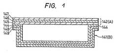
- Fig. 1 is a cross-sectional view of the container according to the invention.
- Figs. 1A to 1C and 2 show a container in accordance with another embodiment of the present invention;
- Figs. 3 to 9 illustrate a method of producing a cylindrical container in accordance with the present invention; and
- Figs. 10and 11 show a cover according to the material of the receptacle, namely, the cover is formed by a sheet composed of a layer of metal foil having a layer of hot-melt resin provided on at least one side thereof. The cover is attached to the container body by a heat sealing step whereby the hot-melt resin of the cover is fused with the adjacent hot-melt resin layer of the container body.
- As shown in Fig. 1, a container comprises a
cover 142 composed of acenter foil layer 142 covered by two hot-melt resin layers 145 and 147 on the opposite sides thereof. Thecontainer body 141 is composed of a centermetal foil layer 148 covered by hot-melt resin layers layers - Next, results of retorting tests performed on can-like containers of the present invention will be discussed. The retorting tests were made under the following conditions, wherein a rectangular container as depicted in Fig. 1 was filled with water and covered as illustrated in Fig. 1:
- Retorting conditions:
- Temperature: 120°C
- Period: 20 min., and
- Pressure: 2 to 3 kg/cm2.
- The material used for the container body was a sheet of aluminum foil laminated with ethylenepropylene block copolymer (CPP-MFR 1.1 and concentration of ethylene=9 wt%) on both sides of the aluminum foil. The thickness of the aluminum foil was 15 pm, the thickness of the outer resin layer was 30 µm, and the thickness of the inner resin layer was 70 pm. The structure of the cover was similar except that the thickness of the aluminum foil was 12 µm, the thickness of the inner resin layer was 70 pm, and the thickness of the outer resin layer was 12 µm.
- The results of the Retorting Tests are presented in Table 1 below:

- As indicated in Table 1, the amount of water charged in the container was varied from full capacity (150 cc) to 50% of full capacity (75 cc) without rupture or puncture of the container, indicating that the container had sufficient strength. As Table 1 further indicates, the use of either tucks or vertical wrinkles provides acceptable results, that is, no pin-holes are formed and no separation occurs with a container of the invention.
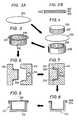
- Referring now to Figs. 1A through 1C, a further modification of the present invention will be described. In accordance with this embodiment, a cover A, formed in the same manner as the
cover 142 is attached to a receptacle B, constructed in the same manner as thecontainer body 141, and the container B is set in a tray C having the same general configuration as the container body B. Fig. 2 is a longitudinal cross-sectional view showing the assembly of the cover A, container body B and tray C. - The tray can be made from plastics. The plastic tray may be formed by injection molding of resin to the outer side of the container body B. It is preferred that the thickness of the tray be sufficient to support the container body and prevent its deformation during transportation and stacking.
- As shown in Fig. 2, the container body B is fitted in the tray C in such a manner that the inner side of the, latter is adhered to the outer side of the former.
- A further explanation will be made as to a method of directly injection molding an outer tray by way of example of a cylinder-shaped container.
- An aluminum-plastic laminate film having an ethylene-
propylene copolymer film 202 to 70 p thickness, analuminum foil 201 of 20 µ thickness and apolypropylene film 203 of 30 µ thickness as shown in Fig. 3B is punched out for obtaining adisc 204 as shown in Fig. 3A. The obtaineddisc 204 of aluminum-plastic laminate film is placed between amale mold 205 and afemale mold 206 havingvertical grooves male mold 205 is pressed into a hollow portion of thefemale mold 206, thereby obtaining an aluminum foil-plastic laminate container 209 having a cylindrical shape provided with vertical wrinkles as shown in Fig. 5. The cylindrical aluminum-plastic laminate container 209 is set on amale mold 212 for injection molding as shown in Fig. 6. Then, afemale mold 213 is aligned with themale mold 212 on which thecontainer 209 is mounted. Under a suitable pressure, ethylene-propylene block copolymer is injected as shown in Fig. 7. The thickness of the ethylene-propylene block copolymer layer is about 700 microns. Then, the contacting surfaces of the aluminum-plastic laminate container 209 and the injection moldedtray 214 are melt bonded intimately to each other. Thus, an integrated rigid aluminum foil-plastic composite container 215 is obtained as shown in Fig. 8. The vertical wrinkles of thecontainer 209 are smoothed by the resin pressure of the injection molding. Thus, the container has a smoothed inner surface. - After filling the aluminum foil-
plastic composite container 215 with a desired content, alaminate film 216 composed of 12 p polyester (PET)/20 p aluminum foil 70 p easy peel film is placed on thecontainer 215 as shown in Fig. 9. Then, the marginal portions are heat sealed to thereby obtain a completely sealed aluminum-plastic composite container 217. More specifically, thecontainer 209 and thetray 214 are heat bonded at their flanged portions to thecover 216 as shown in Fig. 9. The easy-peel film is made of blended film of ethylene-propylene block copolymer 50% and low density polyethylene 50%. - In accordance with the above-described method, the aluminum-
plastic composite container 217 of capacity of 120 cc which was filled with corn soup was retort processed. The following results of ability of preserving the content for a long period were obtained. - Temperature: 120°C
- Period: 20 min.
- Pressure: 2 to 3 kg/cm2

- With the use of a tray, the can-like container according to the present invention is made yet more rigid, thereby making it possible to use an even thinner metal foil layer in the container body.
- Further, a cover structure of the invention will now be described. In Figs. 10 and 11,
reference numeral 3 as before designates the cover; 58, an opening part formed by the second resin layer; 59, a peripheral part formed by the second resin layer; and 60, a slot. Theslot 60 is in the form of a closed ring as shown in Fig. 10, and therefore theopening part 58 is completely separated from theperipheral part 59 by theslot 60. Further, in Figs. 10 and 11,reference numeral 11 designates a handle provided on theopening part 58; and 62, acutting opening part 62 by agroove 63. - In Fig. 11,
reference numeral 64 designates a multi-layer sheet. In the case of Fig. 11, the multi-layer sheet is manufactured by forming first resin layers 66 and 67 on both sides of a gas barrier type base material. The can-like container'scover 3 according to the invention is fixedly mounted on the side wall 1 of the can-like container as shown in Fig. 11. - The
rectangular cover 3 is opened as follows: When the handle 15 is raised with the fingertip inserted intogroove 63, the handle 15 is peeled off themultilayer sheet 64. As a result, theend 69 of the handle 1 goes inside themulti-layer sheet 64 to cut the latter. When, under this condition, the handle 15 is pulled, themulti-layer sheet 64 is cutalong_the slot 60 so that theopening part 58 of the cover is opened. - In the container's cover according to the invention, the opening
part 58 is completely separated from theperipheral part 59 byIme slot 60; i.e., no bridge is provided between theparts 68 and 69. Therefore, the openingpart 58 can be readily opened. This readily openable container's cover can be produced using an injection molding method of the invention. The method will be described with reference to Figs. 10 and 11. The openingpart 58 and theperipheral part 59 are moided using respective gates. That is, the openingpart 58 is independently molded using its gate, while theperipheral part 59 is also independently molded by using its own gate. Theslot 60 is formed by the mold. At least one gate should be provided for molding theopening part 58, and similarly at least one gate should be provided for molding theperipheral part 59. The positions of the gates are indicated by reference characters 70 (G1) and 71 (G2) in Fig. 10. That is, the openingpart 58 is molded using the gate 70 (G1), while theperipheral part 59 is molded using the gate 71 (G2). - In the injection molding method using a plurality of gates, the moldability is excellent and the injection molding operation can be achieved readily. Therefore, materials having allowed moldability such as materials having small melting factors (MFR) resins with filters can be used in the injection molding method. As was described before, in the conventional method, it is necessary to take the moldability into consideration, i.e., it is necessary to select materials having a high fluidity, and it is difficult to use resins with filters. However, these problems have been solved by the provision of the injection molding method according to the invention.
- Furthermore, in the molding method of the invention, the molding temperature and the injection pressure are considerably low, and the productivity (molding cycle) is high. In addition, in the invention, the slot is formed by the pushing action of the metal mold, and therefore, it is preferable that the mold closing pressure is suitable for increasing the durability of the metal mold, preventing damage to the base material and preventing breakage of the slot. According to the invention, the mold closing pressure can be low. Depending on molding conditions, sometimes a product's corner material such as an aluminum foil may be broken in the mold during injection molding. However, such a problem can be eliminated by the low injection pressure employed with the invention.
- According to the injection molding method of the invention, can-like container's covers having a high adhesion strength can be obtained as described above. Especially when a multi-layer sheet having thermally meltable first resin layers on its both sides is used, the first and second resin layers are in a molten state when molded, and are then welded together. Therefore, the resultant molding is high in adhesion strength and accordingly durable in the drop test.
- On the other hand, the cover may suffer from the problem that the handle is also welded to the multi- layer sheet so that it cannot be peeled off the multi-layer sheet. However, this problem can be solved by applying a treatment for allowing the handle to peel off the multi-layer sheet to the part of the multi-layer sheet with which the handle is in contact. An example of the treatment is to use printing ink to form a treatment layer.
- Various modifications of the container of the invention can be contemplated within the scope of the present invention. For instance, although the container body is described above as having shoulders, these shoulders may be dispensed with. In this case, the cover can be heatsealed directly to the tray. Moreover, in the case that the container is to be vacuumed packed, it is recommended that a small hole be formed in the tray so that the container can be degasified to prevent the deformation thereof during the vacuum-packing process. Further, vertical wrinkles can be provided not only on the corner portions but also on the side walls.
- Still further, a modification is anticipated in which a resin similar to that of the outer layer of the container is directly injected over the inner surface of the container, whereby the interface between the injected resin and the container surface is smoothed.


Claims (9)
Applications Claiming Priority (4)
| Application Number | Priority Date | Filing Date | Title |
|---|---|---|---|
| JP19245283AJPS6090130A (en) | 1983-10-17 | 1983-10-17 | Can-shaped vessel |
| JP192452/83 | 1983-10-17 | ||
| JP19343983AJPS6090131A (en) | 1983-10-18 | 1983-10-18 | Can-shaped vessel |
| JP193439/83 | 1983-10-18 |
Publications (4)
| Publication Number | Publication Date |
|---|---|
| EP0140282A2 EP0140282A2 (en) | 1985-05-08 |
| EP0140282A3 EP0140282A3 (en) | 1986-08-13 |
| EP0140282B1true EP0140282B1 (en) | 1990-07-25 |
| EP0140282B2 EP0140282B2 (en) | 1996-01-10 |
Family
ID=26507323
Family Applications (1)
| Application Number | Title | Priority Date | Filing Date |
|---|---|---|---|
| EP84112523AExpired - LifetimeEP0140282B2 (en) | 1983-10-17 | 1984-10-17 | Can-like container and method for manufacturing same |
Country Status (4)
| Country | Link |
|---|---|
| US (2) | US4616766A (en) |
| EP (1) | EP0140282B2 (en) |
| CA (1) | CA1248035A (en) |
| DE (1) | DE3482814D1 (en) |
Families Citing this family (35)
| Publication number | Priority date | Publication date | Assignee | Title |
|---|---|---|---|---|
| JPS6345014A (en)* | 1986-08-13 | 1988-02-26 | Showa Denko Kk | Preforming of part material constituting lid of can-like container |
| FR2607110A1 (en)* | 1986-11-21 | 1988-05-27 | Celatose Ind | Package for a perishable product and its manufacturing method |
| GB2220334B (en)* | 1986-12-24 | 1990-06-13 | Mardon Son & Hall Limited | Microwave heating |
| EP0283534A1 (en)* | 1987-03-24 | 1988-09-28 | Showa Denko Kabushiki Kaisha | Cover for a can-shaped container |
| FR2620076A1 (en)* | 1987-03-31 | 1989-03-10 | Celatose Ind | Process for the production of a package, such as a packaging tray for foodstuffs |
| US5257709A (en)* | 1988-03-29 | 1993-11-02 | Dai Nippon Insatsu Kabushiki Kaisha | Container provided with metallic cover and method and apparatus for manufacturing the same |
| US4877149A (en)* | 1988-11-30 | 1989-10-31 | Showa Denko Kabushiki Kaisha | Scored container top |
| CA1320918C (en)* | 1989-02-13 | 1993-08-03 | Showa Denko Kabushiki Kaisha | Container |
| CH681610A5 (en)* | 1990-04-26 | 1993-04-30 | Alusuisse Lonza Services Ag | |
| DE4030646A1 (en)* | 1990-09-25 | 1992-04-02 | Effem Gmbh | BOWL PACK |
| DE4130905A1 (en)* | 1991-09-17 | 1993-03-18 | Sylvia Dietrich | Plastic foodstuffs package - has dish stiffened on inside by plastic-coated welded cardboard strip forming collar |
| US5302227A (en)* | 1992-03-20 | 1994-04-12 | Kliklok Corporation | Method for closing a heat-resistant carton |
| US5814383A (en)* | 1996-07-23 | 1998-09-29 | Continental Plastic Containers, Inc. | Containers with improved crease-crack resistance |
| US6077273A (en)* | 1996-08-23 | 2000-06-20 | Scimed Life Systems, Inc. | Catheter support for stent delivery |
| US5944726A (en)* | 1996-08-23 | 1999-08-31 | Scimed Life Systems, Inc. | Stent delivery system having stent securement means |
| US6123712A (en) | 1996-08-23 | 2000-09-26 | Scimed Life Systems, Inc. | Balloon catheter with stent securement means |
| US5980530A (en)* | 1996-08-23 | 1999-11-09 | Scimed Life Systems Inc | Stent delivery system |
| JP3968444B2 (en) | 1996-08-23 | 2007-08-29 | ボストン サイエンティフィック サイムド,インコーポレイテッド | Stent delivery mechanism with stent fixation device |
| US6391032B2 (en) | 1996-08-23 | 2002-05-21 | Scimed Life Systems, Inc. | Stent delivery system having stent securement means |
| US6036697A (en)* | 1998-07-09 | 2000-03-14 | Scimed Life Systems, Inc. | Balloon catheter with balloon inflation at distal end of balloon |
| JP2000302147A (en)* | 1999-02-16 | 2000-10-31 | Ishida Co Ltd | Container lid |
| US6682686B1 (en) | 1999-02-16 | 2004-01-27 | Ishida Co., Ltd. | Method of making a container closure |
| US6726714B2 (en)* | 2001-08-09 | 2004-04-27 | Scimed Life Systems, Inc. | Stent delivery system |
| EP1471012A3 (en)* | 2003-04-25 | 2005-01-12 | Ideacorp AG | Method and apparatus for manufacturing cup-shaped containers from material webs |
| US7235093B2 (en)* | 2003-05-20 | 2007-06-26 | Boston Scientific Scimed, Inc. | Mechanism to improve stent securement |
| US7226473B2 (en)* | 2003-05-23 | 2007-06-05 | Brar Balbir S | Treatment of stenotic regions |
| US20040236414A1 (en)* | 2003-05-23 | 2004-11-25 | Brar Balbir S. | Devices and methods for treatment of stenotic regions |
| US20080156831A1 (en)* | 2004-12-01 | 2008-07-03 | Tohru Nakayama | Cartridge for Viscous Fluid Materials |
| ES2487891T3 (en)* | 2004-12-22 | 2014-08-25 | Nestec S.A. | Food container and heating procedure for said container |
| EP2145759A1 (en) | 2008-07-15 | 2010-01-20 | Alcan Technology & Management Ltd. | Laminate and container made of the laminate by deep-drawing |
| IT1392940B1 (en)* | 2009-01-27 | 2012-04-02 | Chiari | BARRIER CONTAINER IN PLASTIC MATERIAL |
| WO2016207826A2 (en)* | 2015-06-24 | 2016-12-29 | E-Wenco S.R.L. | Tub-like container for the containment and packaging of food, made of multilayer sheet material and related method |
| ES2876028T3 (en)* | 2016-06-17 | 2021-11-11 | Tetra Laval Holdings & Finance | Opening system for a container, its manufacturing method and container that comprises the opening system |
| US10945508B2 (en)* | 2017-04-17 | 2021-03-16 | Seal And Pack Co., Ltd. | Two-side adherable high-frequency induction heating container sealing member, compact cosmetic container having tamper function with same applied thereto, and flip cap container having temper function with same applied thereto |
| DE102017109879A1 (en)* | 2017-05-08 | 2018-11-08 | Pester Pac Automation Gmbh | Method for three-dimensional forming of sheet material |
Family Cites Families (14)
| Publication number | Priority date | Publication date | Assignee | Title |
|---|---|---|---|---|
| DE33414C (en)* | 1900-01-01 | J. SCHERBEL und T. REMUS in Dresden | Manufacture of embossed cardboard boxes with a satin finish on the outside and metal edging | |
| US3038634A (en)* | 1957-01-25 | 1962-06-12 | Reynolds Metals Co | Flanged container having controlled corner folds |
| US3298559A (en)* | 1963-10-08 | 1967-01-17 | Continental Can Co | Containers cold-formed from plastic and metal laminate |
| US3558036A (en)* | 1968-10-25 | 1971-01-26 | Us Tobacco Co | Closure for containers |
| US3917155A (en)* | 1972-03-02 | 1975-11-04 | Robert P Bemiss | Carton |
| DE2316513C2 (en)* | 1973-04-03 | 1982-02-25 | Robert Bosch Gmbh, 7000 Stuttgart | Lightweight packaging container made of multilayer composite film material |
| JPS5330742B2 (en)* | 1973-12-28 | 1978-08-29 | ||
| US3885730A (en)* | 1974-03-07 | 1975-05-27 | Christenssons Maskiner | Sterilizable package |
| NL185713C (en)* | 1975-09-12 | 1990-07-02 | Akerlund & Rausing Ab | METHOD FOR MANUFACTURING GAS-PROOF PLASTIC HOLDER |
| CH634789A5 (en)* | 1977-07-29 | 1983-02-28 | Alcan Folien Gmbh | Drawn packaging container made of a composite metal/plastic material |
| US4130236A (en)* | 1977-11-28 | 1978-12-19 | Federal Paper Board Co., Inc. | Tray type container |
| CH636059A5 (en)* | 1979-05-02 | 1983-05-13 | Inauen Masch Ag | PACKING, ESPECIALLY FOR OIL AND FATTY PRODUCTS. |
| AU7022481A (en)* | 1980-05-12 | 1981-11-19 | Federal Paper Board Company Inc. | Baking tray |
| GB2123786A (en)* | 1982-05-14 | 1984-02-08 | Bowater Packaging Ltd | Covered containers |
- 1984
- 1984-10-17EPEP84112523Apatent/EP0140282B2/ennot_activeExpired - Lifetime
- 1984-10-17USUS06/661,747patent/US4616766A/ennot_activeExpired - Lifetime
- 1984-10-17DEDE8484112523Tpatent/DE3482814D1/ennot_activeExpired - Lifetime
- 1984-10-17CACA000465655Apatent/CA1248035A/ennot_activeExpired
- 1986
- 1986-03-11USUS06/838,488patent/US4735665A/ennot_activeExpired - Lifetime
Also Published As
| Publication number | Publication date |
|---|---|
| EP0140282A2 (en) | 1985-05-08 |
| US4616766A (en) | 1986-10-14 |
| EP0140282A3 (en) | 1986-08-13 |
| US4735665A (en) | 1988-04-05 |
| EP0140282B2 (en) | 1996-01-10 |
| CA1248035A (en) | 1989-01-03 |
| CA1254708C (en) | 1989-05-30 |
| DE3482814D1 (en) | 1990-08-30 |
Similar Documents
| Publication | Publication Date | Title |
|---|---|---|
| EP0140282B1 (en) | Can-like container and method for manufacturing same | |
| EP0435638B1 (en) | Easily openable sealed container and process for producing the same | |
| US5954217A (en) | Packaging container and method of manufacturing the same | |
| EP1052182B1 (en) | Plastic container and method for manufacturing same | |
| EP0262652B1 (en) | Easily-openable packaging container and lid for the same | |
| US4775076A (en) | Sealed package, method for manufacturing and utilization of said package | |
| JPH05201436A (en) | Opening device and manufacturing method thereof | |
| JP5931340B2 (en) | Packaging container, packaging container manufacturing method and manufacturing apparatus | |
| JP3365748B2 (en) | Manufacturing method of sealed container | |
| JP4358004B2 (en) | Insulated composite container | |
| JPH0567508B2 (en) | ||
| JP3867474B2 (en) | Easy-open composite film and packaging container | |
| JP3691814B2 (en) | Sealed container | |
| KR100364114B1 (en) | Packing container manufacturing method | |
| JP4043590B2 (en) | Cup composite container with sauce | |
| JP2571569B2 (en) | Easy-open sealed container with drop lid for container | |
| JPS6133943A (en) | Vessel cover | |
| JP4655396B2 (en) | Manufacturing method of cup-shaped container | |
| JPH0267125A (en) | Preparation of hermetically sealed container | |
| JP3471934B2 (en) | Manufacturing method of packaging container | |
| JP4022949B2 (en) | Liquid paper container with drinking mouth | |
| JPH0431851B2 (en) | ||
| JPH08156903A (en) | Manufacturing method of packaging container | |
| JPH0398873A (en) | Manufacture of sealed container | |
| JPH09124044A (en) | Composite container with extractor |
Legal Events
| Date | Code | Title | Description |
|---|---|---|---|
| PUAI | Public reference made under article 153(3) epc to a published international application that has entered the european phase | Free format text:ORIGINAL CODE: 0009012 | |
| AK | Designated contracting states | Designated state(s):BE CH DE FR GB IT LI NL SE | |
| PUAL | Search report despatched | Free format text:ORIGINAL CODE: 0009013 | |
| AK | Designated contracting states | Kind code of ref document:A3 Designated state(s):BE CH DE FR GB IT LI NL SE | |
| 17P | Request for examination filed | Effective date:19860728 | |
| 17Q | First examination report despatched | Effective date:19870313 | |
| GRAA | (expected) grant | Free format text:ORIGINAL CODE: 0009210 | |
| AK | Designated contracting states | Kind code of ref document:B1 Designated state(s):BE CH DE FR GB IT LI NL SE | |
| ET | Fr: translation filed | ||
| REF | Corresponds to: | Ref document number:3482814 Country of ref document:DE Date of ref document:19900830 | |
| ITF | It: translation for a ep patent filed | ||
| PLBI | Opposition filed | Free format text:ORIGINAL CODE: 0009260 | |
| 26 | Opposition filed | Opponent name:AB AKERLUND & RAUSING Effective date:19910423 | |
| NLR1 | Nl: opposition has been filed with the epo | Opponent name:AB AKERLUND & RAUSING | |
| ITTA | It: last paid annual fee | ||
| EAL | Se: european patent in force in sweden | Ref document number:84112523.0 | |
| PUAH | Patent maintained in amended form | Free format text:ORIGINAL CODE: 0009272 | |
| STAA | Information on the status of an ep patent application or granted ep patent | Free format text:STATUS: PATENT MAINTAINED AS AMENDED | |
| 27A | Patent maintained in amended form | Effective date:19960110 | |
| AK | Designated contracting states | Kind code of ref document:B2 Designated state(s):BE CH DE FR GB IT LI NL SE | |
| REG | Reference to a national code | Ref country code:CH Ref legal event code:AEN Free format text:MAINTIEN DU BREVET DONT L'ETENDUE A ETE MODIFIEE | |
| NLR2 | Nl: decision of opposition | ||
| NLR3 | Nl: receipt of modified translations in the netherlands language after an opposition procedure | ||
| ITF | It: translation for a ep patent filed | ||
| ET3 | Fr: translation filed ** decision concerning opposition | ||
| APAC | Appeal dossier modified | Free format text:ORIGINAL CODE: EPIDOS NOAPO | |
| APAC | Appeal dossier modified | Free format text:ORIGINAL CODE: EPIDOS NOAPO | |
| PGFP | Annual fee paid to national office [announced via postgrant information from national office to epo] | Ref country code:SE Payment date:20001009 Year of fee payment:17 Ref country code:DE Payment date:20001009 Year of fee payment:17 | |
| PGFP | Annual fee paid to national office [announced via postgrant information from national office to epo] | Ref country code:FR Payment date:20001010 Year of fee payment:17 | |
| PGFP | Annual fee paid to national office [announced via postgrant information from national office to epo] | Ref country code:GB Payment date:20001011 Year of fee payment:17 | |
| PGFP | Annual fee paid to national office [announced via postgrant information from national office to epo] | Ref country code:NL Payment date:20001026 Year of fee payment:17 Ref country code:CH Payment date:20001026 Year of fee payment:17 | |
| PGFP | Annual fee paid to national office [announced via postgrant information from national office to epo] | Ref country code:BE Payment date:20001214 Year of fee payment:17 | |
| PG25 | Lapsed in a contracting state [announced via postgrant information from national office to epo] | Ref country code:GB Free format text:LAPSE BECAUSE OF NON-PAYMENT OF DUE FEES Effective date:20011017 | |
| PG25 | Lapsed in a contracting state [announced via postgrant information from national office to epo] | Ref country code:SE Free format text:LAPSE BECAUSE OF NON-PAYMENT OF DUE FEES Effective date:20011018 | |
| PG25 | Lapsed in a contracting state [announced via postgrant information from national office to epo] | Ref country code:LI Free format text:LAPSE BECAUSE OF NON-PAYMENT OF DUE FEES Effective date:20011031 Ref country code:CH Free format text:LAPSE BECAUSE OF NON-PAYMENT OF DUE FEES Effective date:20011031 Ref country code:BE Free format text:LAPSE BECAUSE OF NON-PAYMENT OF DUE FEES Effective date:20011031 | |
| REG | Reference to a national code | Ref country code:GB Ref legal event code:IF02 | |
| BERE | Be: lapsed | Owner name:SHOWA DENKO K.K. Effective date:20011031 | |
| PG25 | Lapsed in a contracting state [announced via postgrant information from national office to epo] | Ref country code:NL Free format text:LAPSE BECAUSE OF NON-PAYMENT OF DUE FEES Effective date:20020501 | |
| EUG | Se: european patent has lapsed | Ref document number:84112523.0 | |
| GBPC | Gb: european patent ceased through non-payment of renewal fee | Effective date:20011017 | |
| REG | Reference to a national code | Ref country code:CH Ref legal event code:PL | |
| PG25 | Lapsed in a contracting state [announced via postgrant information from national office to epo] | Ref country code:FR Free format text:LAPSE BECAUSE OF NON-PAYMENT OF DUE FEES Effective date:20020628 | |
| NLV4 | Nl: lapsed or anulled due to non-payment of the annual fee | Effective date:20020501 | |
| PG25 | Lapsed in a contracting state [announced via postgrant information from national office to epo] | Ref country code:DE Free format text:LAPSE BECAUSE OF NON-PAYMENT OF DUE FEES Effective date:20020702 | |
| REG | Reference to a national code | Ref country code:FR Ref legal event code:ST | |
| APAH | Appeal reference modified | Free format text:ORIGINAL CODE: EPIDOSCREFNO |