EP0138090B1 - Radio-wave transmission system of keyless entry system for automotive vehicle devices - Google Patents
Radio-wave transmission system of keyless entry system for automotive vehicle devicesDownload PDFInfo
- Publication number
- EP0138090B1 EP0138090B1EP84111198AEP84111198AEP0138090B1EP 0138090 B1EP0138090 B1EP 0138090B1EP 84111198 AEP84111198 AEP 84111198AEP 84111198 AEP84111198 AEP 84111198AEP 0138090 B1EP0138090 B1EP 0138090B1
- Authority
- EP
- European Patent Office
- Prior art keywords
- signal
- code
- controller
- transmitter
- antenna
- Prior art date
- Legal status (The legal status is an assumption and is not a legal conclusion. Google has not performed a legal analysis and makes no representation as to the accuracy of the status listed.)
- Expired - Lifetime
Links
Images


Classifications
- G—PHYSICS
- G07—CHECKING-DEVICES
- G07C—TIME OR ATTENDANCE REGISTERS; REGISTERING OR INDICATING THE WORKING OF MACHINES; GENERATING RANDOM NUMBERS; VOTING OR LOTTERY APPARATUS; ARRANGEMENTS, SYSTEMS OR APPARATUS FOR CHECKING NOT PROVIDED FOR ELSEWHERE
- G07C9/00—Individual registration on entry or exit
- G07C9/00174—Electronically operated locks; Circuits therefor; Nonmechanical keys therefor, e.g. passive or active electrical keys or other data carriers without mechanical keys
- G07C9/00309—Electronically operated locks; Circuits therefor; Nonmechanical keys therefor, e.g. passive or active electrical keys or other data carriers without mechanical keys operated with bidirectional data transmission between data carrier and locks
- B—PERFORMING OPERATIONS; TRANSPORTING
- B60—VEHICLES IN GENERAL
- B60R—VEHICLES, VEHICLE FITTINGS, OR VEHICLE PARTS, NOT OTHERWISE PROVIDED FOR
- B60R25/00—Fittings or systems for preventing or indicating unauthorised use or theft of vehicles
- B60R25/20—Means to switch the anti-theft system on or off
- B60R25/24—Means to switch the anti-theft system on or off using electronic identifiers containing a code not memorised by the user
- B60R25/246—Means to switch the anti-theft system on or off using electronic identifiers containing a code not memorised by the user characterised by the challenge triggering
- G—PHYSICS
- G07—CHECKING-DEVICES
- G07C—TIME OR ATTENDANCE REGISTERS; REGISTERING OR INDICATING THE WORKING OF MACHINES; GENERATING RANDOM NUMBERS; VOTING OR LOTTERY APPARATUS; ARRANGEMENTS, SYSTEMS OR APPARATUS FOR CHECKING NOT PROVIDED FOR ELSEWHERE
- G07C9/00—Individual registration on entry or exit
- G07C9/00174—Electronically operated locks; Circuits therefor; Nonmechanical keys therefor, e.g. passive or active electrical keys or other data carriers without mechanical keys
- G07C9/00309—Electronically operated locks; Circuits therefor; Nonmechanical keys therefor, e.g. passive or active electrical keys or other data carriers without mechanical keys operated with bidirectional data transmission between data carrier and locks
- G07C2009/00507—Electronically operated locks; Circuits therefor; Nonmechanical keys therefor, e.g. passive or active electrical keys or other data carriers without mechanical keys operated with bidirectional data transmission between data carrier and locks keyless data carrier having more than one function
- G—PHYSICS
- G07—CHECKING-DEVICES
- G07C—TIME OR ATTENDANCE REGISTERS; REGISTERING OR INDICATING THE WORKING OF MACHINES; GENERATING RANDOM NUMBERS; VOTING OR LOTTERY APPARATUS; ARRANGEMENTS, SYSTEMS OR APPARATUS FOR CHECKING NOT PROVIDED FOR ELSEWHERE
- G07C9/00—Individual registration on entry or exit
- G07C9/00174—Electronically operated locks; Circuits therefor; Nonmechanical keys therefor, e.g. passive or active electrical keys or other data carriers without mechanical keys
- G07C2009/00753—Electronically operated locks; Circuits therefor; Nonmechanical keys therefor, e.g. passive or active electrical keys or other data carriers without mechanical keys operated by active electrical keys
- G07C2009/00769—Electronically operated locks; Circuits therefor; Nonmechanical keys therefor, e.g. passive or active electrical keys or other data carriers without mechanical keys operated by active electrical keys with data transmission performed by wireless means
- G07C2009/00793—Electronically operated locks; Circuits therefor; Nonmechanical keys therefor, e.g. passive or active electrical keys or other data carriers without mechanical keys operated by active electrical keys with data transmission performed by wireless means by Hertzian waves
- Y—GENERAL TAGGING OF NEW TECHNOLOGICAL DEVELOPMENTS; GENERAL TAGGING OF CROSS-SECTIONAL TECHNOLOGIES SPANNING OVER SEVERAL SECTIONS OF THE IPC; TECHNICAL SUBJECTS COVERED BY FORMER USPC CROSS-REFERENCE ART COLLECTIONS [XRACs] AND DIGESTS
- Y10—TECHNICAL SUBJECTS COVERED BY FORMER USPC
- Y10T—TECHNICAL SUBJECTS COVERED BY FORMER US CLASSIFICATION
- Y10T70/00—Locks
- Y10T70/50—Special application
- Y10T70/5889—For automotive vehicles
- Y10T70/5973—Remote control
- Y10T70/5978—With switch
Definitions
- the present inventionrelates to a keyless operating system, especially a system for operating lock devices such as door locks, a trunk lid lock, a glove box lid lock, a steering lock device, a starter motor, etc. without mechanical keys.
- a keyless operating systemespecially a system for operating lock devices such as door locks, a trunk lid lock, a glove box lid lock, a steering lock device, a starter motor, etc. without mechanical keys.
- an entry systemWhen such a system is used to operate door locks, it is called an entry system.
- keyboardsmounted at the outside of the vehicle body to allow entry by inputting a predetermined code.
- the designated vehicle devicesare electrically operated when the entered code matches a predetermined code.
- US-A-3,891,980describes a security system for opening doors within protected areas automatically.
- An authorized personcarries in his pocket a transmitter generating a coded signal to be received by a controller.
- the controllercomprises three antennas each one being rectangularly arranged to the other both antennas. As soon as by these antennas a signal is received having the code matching with a predetermined code, a door, near to which the antennas are located, is opened automatically. As long as the correct code is received by the controller, it is not possible to set the door either to an active or an inactive state - the door always will remain activated, i. e. it will remain open.
- GB-A-2 051 442describes an entry system for an automotive vehicle which makes also use of transmitted coded signals.
- a keyis required to lock and unlock the vehicle doors. As soon as somebody tries to unlock the door with a key, an alarm will sound, when a controller of the entry system does not receive a correctly coded signal from a transmitter.
- a keyless entry system using a keyboardhas the disadvantage that a driver cannot enter his car when he forgets the predetermined code.
- the security/entry-system according to GB-A-2 051 442has the conventional disadvantage of all systems necessating a key for unlocking the doors: The driver cannot enter his car when he forgot or lost the key.
- the keyless operating system of the present inventioncomprises:
- This systemcomprises a radio signal system and a manual switch for operating with each other. Only when the manual switch is operated, the radio signal system becomes active, and only as soon as the radio wave signal has become active, operation of the manual switch can provide a reversal of the state of an allocated vehicular device.
- a manual switch and a controller antenna arrangementis associated to each device. In such an embodiment it is possible to operate different devices independently from each other.
- a controller antenna arrangementcomprising a first antenna and a second antenna which both antennas are arranged rectangular to each other.
- the first embodiment of a keyless entry system for an automotive vehiclegenerally comprises a code transmitter 100 and a controller 200.
- the controller 200is connected via a driver signal generator 204 to actuators 202 for vehicle devices such as door lock device, a trunk lid lock device, a groove box lid locks and a steering lock device.
- the transmitter 100is provided with an antenna 104 which is built into a transmitter casing 116.
- the antenna 104is a loop antenna.
- the controller 200is provided with a pair of loop antennas 214 and 215.
- the antennas 214 and 215are provided on surfaces lying essentially perpendicular to each other.
- the antenna 214is mounted on a vehicle side-window at a position near an outside door handle 219 which is mounted on a vehicle door 217 by means of an outside door handle escutcheon 218.
- the outside door handle escutcheon 218also supports one or more manually operable push-button switches 210.
- the antenna 215is mounted on a door mirror 221 mounted at the forward corner of a front side-door 223.
- the mirror surface of the door mirror 221lies essentially perpendicular to the surface of the side-window.
- the antennas 214 and 215are connected to the controller circuit through a switching circuit 231 which alternatingly and selectively connects one of the antennas 214 and 215 to the controller circuit.
- the controller 200includes a demand signal SD generator 208 which sends a demand signal SD to the transmitter 100 to activate the latter.
- the demand signal SD generator 208is connected to the manual switches 210.
- the demand signal SD generator 208produces a demand signal SD when one of the manual switches 210 is depressed.
- the transmitter 100includes a receiver circuit 102 for receiving the demand signal SD from the controller.
- the transmitter 100becomes active when the receiving circuit 102 receives the demand signal SD to produce a code signal SC which is indicative of a preset specific code.
- the preset code of the portable transmitter 100differs from that of the demand signal SD generator 208 so that the controller 200 can recognize when the transmitter 100 is responding.
- the transmitter 100continuously transmits the code signal SC to the controller for as long as it remains active.
- the code signal SCis received by a receiver 212 in the controller 200.
- the controller 200has a comparator 213 to compare the received code with a specific preset code. When the received code matches the code preset as compared in the comparator 213, the controller 200 sends a control signal SL to the driver circuit generator 204.
- the driver signal generator 204in turn sends a drive signal to one of the actuators 202 corresponding to the manual switch 210 operated.
- the actuator 202in activated by the driver signal from the driver signal generator 204 to operate the corresponding vehicle device.
- Transmission of the demand signal SD and the code signal SCis performed by way of electromagnetic induction between the antennas 104 and 214 or 104 and 215.
- the strength of the electromagnetic inductiondepends on the orientation of the active antenna 214 or 215 relative to the antenna 104 of the transmitter. For instance, when the antenna 104 of the transmitter 100 is approximately perpendicular to the antenna 214 as shown in Fig. 7, the strength of the transmitted demand signal SD or code signal SC is rather low and possibly too low to be received.
- the antenna 104lies approximately parallel to the antenna 215, relatively strong electromagnetic induction will occur between the antennas, ensuring satisfactory transmission of code data. Therefore, by selectively activating the more nearly parallel of the antennas 214 and 215, reception of the code data can be assured.
- the actuators 202actuate the vehicle devices from the current position to the opposite position in response to the driver signal. For instance, when the vehicle device is in the locked position, the actuator unlocks the vehicle device in response to the driver signal. On the other hand, when the driver signal is sent to the actuator of a vehicle device which currently unlocked, that vehicle device is then locked.
- the transmitter 100includes a transmitter/receiver antenna 104.
- a loop antenna 214is built into one of the windows 216 of the vehicle.
- the loop antenna 214transmits the demand signal SD to and receives the code signal SC from the transmitter 100.
- the manual switches 210are mounted on an escutcheon 218 of an outside door handle for operation from outside the vehicle.
- the transmitter 100is housed in a case small enough to hand-carry or to pocket.
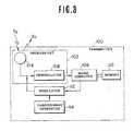
- Fig. 3shows the circuit structure of the transmitter 100.
- a microprocessor 106is connected to the antenna 104 via a demodulator 108 which demodulates the received demand signal SD.
- the microprocessor 106includes a memory 110 storing the preset code.
- the microprocessor 106reads out the preset code to a modulator 112.
- the modulator 112is, in turn, connected to a carrier-wave generator 114 to receive a carrier wave.
- the modulator 112modulates the carrier-wave with the code-indicative signal from the microprocessor 106 to produce the final code signal SC.
- the antenna 104 of the transmitter 100is built into the transmitter circuit board or on the surface of the transmitter casing 116 (shown in Fig. 2).
- the casing 116is the size of a name card and thin enough to carry in a shirt pocket.
- the transmitter 100uses a long-life, compact battery, such as a mercury battery, as a power source.
- Fig. 4shows the circuitry of the controller 200.
- the shown embodiment of the keyless entry systemis adapted to operate the door locks, the trunk lid lock, the glove box lock and the steering lock device.
- the shown embodimentis adapted to control operation of the locks for the right- and left-side doors independently.
- manual switches 210-DR, 210-DL, 210-TL, 210-GL and 210-STare provided on the vehicle body somewhere nearby the devices to be operated.
- the manual switches 210-DR and 210-DLare provided adjacent the door handles of respectively corresponding side soors.
- the manual switch 210-TL to operate the trunk lid lock devicewould be placed adjacent the trunk lid.
- Each manual switchis operable independently to operate the corresponding lock device. For example, when the manual switch 210-DR is depressed, the right-side door lock 220-DR is actuated to either to the locked or unlocked state.
- Each manual switch 210-DR, 210-DL, 210-TL, 210-GL and 210-STis connected to a timer 222-DR, 222-DL, 222-TL, 222-GL and 222-ST through a normally closed relay
- Each manual switch 210-DR, 210-DL, 210-TL, 210-GL and 210-STis connected to a timer 222-DR, 222-DL, 222-TL, 222-GL and 222-ST through a normally closed relay 224-DR, 224-DL, 224-TL, 224-GL and 224-ST.
- the timerswhich will be referred to generically with reference numeral "222”, are responsive to depression of the corresponding manual switch, which will be referred to generically with reference numeral "210”, to produce a HIGH-level timer signal St for a given period of time.
- the timer signal Stis fed to a corresponding AND-gate 226-DR, 226-DL, 226-TL, 226-GL and 226-ST, which will be referred to generically with reference numeral "226".
- the timer signal Stis fed to a corresponding switching circuit 227-DR, 227-DL, 227-TL, 227-GL and 227-ST, which will be referred to generically with reference numeral "227".
- Each switching circuit 227-DR, 227-DL, 227-TL, 227-GL and 227-STincludes a pair of switching elements 228-DR, 228-DL, 228-TL, 228-GL or 228-ST which will be referred to generally with reference numeral "228", and 229-DR, 229-DL, 229-TL, 229-GL and 229-ST which will be referred to generally with reference numeral "229”.
- the switching elements 228-DR, 228-DL, 228-TL, 228-GL or 228-STare connected the corresponding antenna 214-DR, 214-DL, 214-TL, 214-GL or 214-ST, which will be referred to generically with reference numeral "214".
- the switching elements 229-DR, 229-DL, 229-TL, 229-GL or 229-STare connected the corresponding antenna 215-DR, 215-DL, 215-TL, 215-GL or 215-ST, which will be referred to generically with reference numeral "215".
- the antennas 214-DR, 214-DL, 214-TL, 214-GL or 214-STare located adjacent respectively corresponding vehicle devices to be operated.
- the antennas 214-DR and 214-DLare mounted on respectively corresponding side windshields
- the antenna 214-TL for operating the trunk lid lock devicemay be provided on the rear windshield or the edge of rear windshield opening
- antennas 214-ST and 214-GL for steering lock device and the glove box lid lock devicemay be mounted on the front windshield or along the edge of the front windshield opening.
- the switching elements 228closes in response to the timer signal St to connect the corresponding antenna 214-DR, 214-DL, 214-TL, 214-GL or 214-ST, which will be referred to generically with reference numeral "214", to the switching circuit 231 via a conductive line 223a.
- the switching elements 229close in response to the timer signal St to connect the corresponding antennas 215-DR, 215-DL, 215-TL, 215-GL and 215-ST to the switching circuit 231 through a conductive line 233b.
- the switching circuit 231is, in turn, connected to a demodulator 230 which demodulates the code signal SC to remove the carrier-wave.
- the switching circuitis also connected to a microprocessor 232 to receive a switching signal Ss in response to which it switches between its first and second switch positions.
- the switching circuit 231connects the conductive line 223a to the demodulator 230 to feed the input code signal SC received by one of the antennas 214 to the demodulator 230.
- the switching circuit 231connects the conductive line 223b to the demodulator 230 to feed the input code signal SC received by one of the antennas 215 to the demodulator.
- the timers 222are also all connected to a microprocessor 232 via a multi-input OR gate 234.
- the microprocessor 232includes a memory 236 which stores the preset code corresponding to that stored in the transmitter 100.
- the microprocessor 232responds to the timer signal St received via the OR gate 234 by outputting the demand signal SD to the transmitter through a modulator 238 and antenna 214.
- the modulator 238is connected to the antennae 214 via the switching circuits 228 to transmit the demand signal SD to the transmitter 100.
- the microprocessor 232receives the code signal SC via the antenna 214 and the demodulator 230 and compares the received code with the stored code. When the received code matches the stored code, the microprocessor 232 outputs the control signal SL to the other input terminal of the AND gate 226 corresponding to the depressed manual switch.
- AND gate 226transmits a HIGH-level signal to the driver signal generator 204-DR, 204-DL, 204-TL, 204-GL or 204-ST, which will be referred to generically with reference numeral "204".
- the driver signal generator 204responds to the HIGH-level signal by outputting a driver signal to the corresponding actuator 202-DR, 202-DL, 202-TL, 202-GL or 202-ST of the lock 220-DR, 220-DL, 220-TL, 220-GL or 220-ST.
- the microprocessor 106 of the transmitter 100repeatedly executes the first control program illustrated in Fig. 5(A).
- the microprocessor 106checks for receipt of the demand signal SD from the controller at a step 1002.
- the step 1002is repeated until the demand signal SD is received.
- the transmitter 100normally remains in a stand-by state, waiting to produce the code signal SC in response to the demand signal SD.
- the preset codeis read from the memory 110 at a step 1004.
- the microprocessor 106then outputs the code-indicative signal to the modulator 112 which in turn outputs the code signal SC in step 1006. Control then returns to the stand-by step 1002.
- the code signal SCis transmitted from the modulator to the controller for a given period of time and terminates when the given period of time expires.
- the given period of time during which the code signal SC is transmittedis so chosen that the controller 200 can activate the actuator 202 designated by the operated manual switch before expiration of that period.
- the code stored in the memory 110is preferably a binary code, such as an 8-bit serial datum. This binary code rides on the carrier wave as modulated by the modulator to form the code signal SC.
- Fig. 5(B)is a flowchart for the controller.
- the microprocessor 232checks for receipt of the timer signal St at a step 2002. If the timer signal St is not detected when checked at the step 2002, the second program ends. This is substantially the same as the loop at the step 1002 in Fig. 5(A) and holds the controller in stand-by until depression of a manual switch.
- the microprocessor 232sends the switching signal Ss to the switching circuit 231 which then switches between its first and second positions, at a step 2004.
- the demand signal SDis produced and output through the modulator 238 and the selected antenna 214 or 215, at a step 2006.
- the code signal SC to be produced at the step 1006 of the first program of Fig. 5(A) in response to the demand signalis checked at a step 2008 to see if it has been received. If the code signal has not yet been received when checked at the step 2008, elapsed time is checked at a step 2010.
- the timer 235 included in the microprocessor 232is activated in response to outputting of the demand signal SD to start measurement of elapsed time. If elapsed time matches or exceeds a given timer threshold, the timer 235 outputs a time-over signal.
- the switching signal Ssis again sent to the switching circuit 231, at a step 2012. Then, at a step 2014, the demand signal is output once again to the transmitter 100 through the modulator 238 and the corresponding one of the antennas 215 or 214. In response to the demand signal SD, the timer 235 is cleared to restart measurement of elapsed time. Receipt of the code signal SC from the transmitter 100 is checked at a step 2016. If the code signal SC is not yet received, elapsed time is again checked at a step 2018. If elapsed time exceeds a predetermined threshold at the step 2016, then the program ends.
- the received code in the code signal SCis read out at a step 2020.
- the preset code of the controller 200is then read out from the memory 236, at a step 2022.
- the input code and the preset code read out in steps 2008 and 2010are compared at a step 2024. If the codes match, a matching flag FM is set at the step 2024.
- the matching flag FMis checked at a step 2026. If the matching flag FM is not set, the program ends. On the other hand, if the matching flag FM is set when checked at the step 2026, then the control signal SL is sent to the driver signal generator at a step 2028.
- the code signal SCis output only when the demand signal SD is input from the controller, consumption of electric power of the battery in the transmitter is significantly reduced in comparison with system which might employ constant transmission of the code signal SC.
- the life-time of the battery of the transmitteris prolonged even though electric power is constantly supplied to the microprocessor to hold same in stand-by. It should be appreciated that the electric power needed to power the microprocessor is substantially smaller than that consumed in transmitting the code signal SC. Therefore, constant power supply to the microprocessor will not significantly affect the life-time of the battery.
- transmission of the demand signal SD and the code signal SCis performed by electromagnetic induction. Since locking and unlocking operations of the lock devices will generally be performed only when the transmitter is near the controller, good communication between the transmitter and the controller can be obtained by electromagnetic induction without significant power consumption.
- the manual switch 210-DRis depressed.
- the timer 222-DRbecomes active to output the timer signal St.
- the timer signal Stis applied to the AND gate 226DR and to the switching elements 228-DR and 229-DR, the latter of which then closes to connect the antenna 214-DR or 215-DR to the microprocessor 232.
- the timer signal St from the timer 222-DRis also input to the microprocessor 232 via the OR gate 234.
- the microprocessor 232responds inputs from the OR gate 234 by activating the modulator 238 to transmit the demand signal SD via the antenna 214-DR or 215-DO.
- the demand signal SD transmitted via the antenna 214-DRis received by the antenna 104 of the transmitter 100. Then, the demand signal SD is demodulated by the demodulator 108 to remove the carrier-wave components.
- the microprocessor 106 of the transmitter 100then executes the steps 1004 and 1006 of the first control program of Fig. 5(A) and outputs the code-indicative signal to the modulator 112.
- the modulator 112thus transmits the code signal SC to the controller 200 via the antenna 104.
- the switching circuit 231is in its first switch position as a result of the first issued switching signal Ss and the antenna 104 of the transmitter 100 is oriented essentially perpendicular to the antenna 214-DR, the response of the antenna 214-DR is apt to be too weak to satisfactory receive the code signal. If receipt of the code signal SC from the transmitter 100 is not confirmed within the given period of time, the switching signal Ss is output once again to switch the switching circuit 231 to its second position. Since in this case, the antenna 215-DR is aligned essentially parallel to the antenna 104, good response characteristics can be achieved. Therefore, in the above case, the code signal SC will be transferred to the demodulator 230 through the antenna 215-DR via the condictive line 233b.
- the code signal SCis received by the antenna 215-DR and fed to the demodulator 230.
- the demodulator 230demodulates the code signal SC to remove the carrier-wave components.
- the microprocessor 232receives the demodulated code signal SC and executes the steps 2008 to 2016 of the second control program.
- the microprocessor 232feeds the control signal SL to the AND gate 226-DR.
- the AND gatepasses a HIGH-level signal to the driver signal generator 204-DR which produces the driver signal.
- the driver signalis applied to the actuator 202-DR of the right-side door lock device 220-DR to reverse the lock position. Since the right-side door lock device 220-DR was originally locked, it becomes unlocked upon activation of the actuator 202-DR.
- the antenna 214-DL or 215-DLsends the code signal SC to the microprocessor via the switching circuit 231 and the demodulator 238. If the input code matches the preset code, the AND gate 226-DL opens to activate the driver signal generator 204-DL. Thus, if the left-side door lock device is originally unlocked, it becomes locked.
- the timer 222-TLWhen the manual switch 210-TL is operated, the timer 222-TL become active to send a timer signal St to the AND gate 226-TL and the switching elements 228-TL and 229-TL.
- the switching circuit 228-TLthen closes to establish electrical communication between the antenna 214-TL or 215-TL and the demodulator 230 and the modulator 238.
- the code signal SCis transmitted from the transmitter 100 to the antenna 214-TL or 215-TL in response to the demand signal SD. If the input code is the same as the preset code, then the AND gate 226-TL opens to activate the driver signal generator 204-TL. Therefore, the trunk lid lock device 220-TL switches from its current position to the other position.
- the timer 222-GLWhen the manual switch 210-GL is operated to open the glove box lid, the timer 222-GL is activated to output the timer signal St. In response to the timer signal St, the switching elements 228-GL and 229-GL establishes electrical communication between the antenna 214-GL and the demodulator 230. The code signal SC transmitted from the transmitter 100 is thus demodulated by the demodulator and input to the microprocessor 232.
- the AND gate 226-GLopens in response to the control signal SL from the microprocessor 232 to activate the driver signal generator 204-GL by the gate signal thereof.
- the actuator 202-GLIn response to the driver signal from the driver signal generator 204-GL, the actuator 202-GL become active to reverse the position of the glove box lid lock from locked state to the unlocked state to allow access to the glove box.
- the manual switch 210-STIn order to release the steering wheel from the locked state, the manual switch 210-ST is depressed.
- the timer 222-STbecomes active to output the timer signal St for the given period of time.
- the antenna 214-ST or 215-STis connected to the microprocessor 232 via the demodulator 230 to receive the code signal SC from the transmitter 100.
- the driver signal generator 204-SToutputs the driver signal to reverse the position of the steering lock device 220-ST from the locked state to the unlocked state.
- Fig. 8shows the second embodiment of a keyless entry system according to the present invention.
- the controller 200is provided with pairs of antennas 214 and 215 arranged perpendicular to each other.
- the antennas 214 and 215are connected to the receiver 212 through a phase converter 250.
- the phase converter 250is adapted to shift the phase of code signals received via the antennas 214 and 215 through 90 o .
- the phase converter 250mixes the phase-shifted code signals and sends the mixed code signal to the demodulator.
- the phase converter 250is also adapted to feed the demand signal SD to the antennas 214 and 215 at phases 90 o apart.
- the field strength induced at the antenna 104 of the transmitter 100can be described by the following equation: where E1 cos ⁇ t is the field component at the antenna 104 due to the demand signal transmitted through the antenna 214; E2 sin ⁇ t is the field component at the antenna 104 due to the demand signal transmitted through the antenna 215.
- the field strength at the antenna 104equal to the vector sum of the strengths of the code signals transmitted from the antennas 214 and 215 is greater than either of the charges E1 and E2 applied to respectively antennas 214 and 215 independently.
- Fig. 9shows the detailed circuitry of the controller of the second embodiment of the keyless entry system according to the present invention.
- a plurality of loop antennas 214-DR, 214-DL, 214-TL, 214-GL and 214-STare provided on the side window surface and a plurality of loop antennas 215-DR, 215-DL, 215-TL, 215-GL and 215-ST are provided on the door mirror surface.
- the antennas 214-DR and 215-DRare associated with the right-side door lock device 220-DR.
- the antennas 214-DL and 215-DLare associated with the left-side door lock device 220-DL.
- the antennas 214-TL and 215-TLcorrespond to the trunk lid lock device 220-TL
- the antennas 214-GL and 215-GLcorrespond to the glove box lid lock device 220-GL
- the antenna 214-ST and 215-STcorrespond to the steering lock device 220-ST.
- Each pair of antennas 214 and 215are connected to the demodulator 230 and the modulator 238 through the phase converter 250.
- the microprocessor 232receives the code signal SC through the demodulator 230 and outputs the demand signal SD.
- the modulator 238modulates the demand-indicative signal from the microprocessor with the carrier-wave from the carrier-wave generator 239.
Landscapes
- Engineering & Computer Science (AREA)
- Computer Networks & Wireless Communication (AREA)
- Physics & Mathematics (AREA)
- General Physics & Mathematics (AREA)
- Mechanical Engineering (AREA)
- Lock And Its Accessories (AREA)
- Near-Field Transmission Systems (AREA)
Description
- The present invention relates to a keyless operating system, especially a system for operating lock devices such as door locks, a trunk lid lock, a glove box lid lock, a steering lock device, a starter motor, etc. without mechanical keys. When such a system is used to operate door locks, it is called an entry system.
- Recently, so-called "keyless entry systems" have been developed using a keyboard mounted at the outside of the vehicle body to allow entry by inputting a predetermined code. The designated vehicle devices are electrically operated when the entered code matches a predetermined code.
- Keyless entry systems are not only used to open vehicle doors but they are also used to open other doors. US-A-3,891,980 describes a security system for opening doors within protected areas automatically. An authorized person carries in his pocket a transmitter generating a coded signal to be received by a controller. The controller comprises three antennas each one being rectangularly arranged to the other both antennas. As soon as by these antennas a signal is received having the code matching with a predetermined code, a door, near to which the antennas are located, is opened automatically. As long as the correct code is received by the controller, it is not possible to set the door either to an active or an inactive state - the door always will remain activated, i. e. it will remain open.
- GB-A-2 051 442 describes an entry system for an automotive vehicle which makes also use of transmitted coded signals. However, a key is required to lock and unlock the vehicle doors. As soon as somebody tries to unlock the door with a key, an alarm will sound, when a controller of the entry system does not receive a correctly coded signal from a transmitter.
- The keyless entry system as described in US-A-3,891,980 cannot be used at an automotive vehicle as the risk of undesired operation would be too high. As soon as the transmitter would be activated unintentionally, e.g. when the driver leaves his car, all door locks would open immediately.
- A keyless entry system using a keyboard has the disadvantage that a driver cannot enter his car when he forgets the predetermined code.
- The security/entry-system according to GB-A-2 051 442 has the conventional disadvantage of all systems necessating a key for unlocking the doors: The driver cannot enter his car when he forgot or lost the key.
- It is an object of the present invention to provide a keyless operating system for an automotive vehicle device which enables a user to activate the device to either an active or an inactive state without requiring a key or inputting a remembered code.
- The keyless operating system of the present invention comprises:
- an electrical actuator connected to said vehicle device and responsive to a control signal to reverse said vehicle device between said active and inactive states;
- a manual switch stationarily mounted at the vehicle and exposed for external access for commanding reversal of the state of said vehicular device;
- a transmitter responsive to a radio demand signal to output a radio code signal indicative of a unique code which identifies the transmitter, which transmitter has a transmitter antenna installed at a transmitter housing and designed for induction radio signal communication;
- and a controller responsive to manual entry of a command through said manual switch for transmitting said radio demand signal through a controller antenna arrangement and receiving said radio code signal from said transmitter through said controller antenna arrangement, comparing the unique code indicated by said radio code signal with a preset code, and producing said control signal, when said unique code matches said preset code.
- This system comprises a radio signal system and a manual switch for operating with each other. Only when the manual switch is operated, the radio signal system becomes active, and only as soon as the radio wave signal has become active, operation of the manual switch can provide a reversal of the state of an allocated vehicular device.
- With this system, devices can be operated without requiring to use a key or to input a remembered code. The system is very secure, as there is no danger that the state of a device changes only by the effect of a radio wave signal. Energy consumption is very low as radio signals on the side of the controller as well as on the side of the transmitter will only be transmitted after the manual switch stationarily mounted at the vehicle is operated.
- In a preferred embodiment, a manual switch and a controller antenna arrangement is associated to each device. In such an embodiment it is possible to operate different devices independently from each other.
- In order to make the signal transfer between the transmitter and the controller as effective as possible, it is preferred to use a controller antenna arrangement comprising a first antenna and a second antenna which both antennas are arranged rectangular to each other.
- The present invention will be understood more fully from the detailed description given here below and from the accompanying drawings of the preferred embodiment of the present invention, which, however, should not be assumed to limit the invention to the specific embodiments but are for explanation and understanding only.
- In the drawings:
- Fig. 1 is a schematic block diagram showing the general concepts of a keyless entry system for an automotive vehicle device according to the present invention;
- Fig. 2 is a perspective view of an automotive vehicle to which the keyless entry system according to the present invention is applied;
- Fig. 3 is a block diagram of a transmitter in the first embodiment of a keyless entry system according to the present invention;
- Fig. 4 is a block diagram of a controller in the first embodiment of the keyless entry system according to the present invention;
- Figs. 5(A) and 5(B) are flowcharts of the operation of the transmitter and the receiver, respectively;
- Fig. 6 is a perspective view of a modification of an ignition switch arrangement;
- Fig. 7 is a block diagram of a modification of the first embodiment of the keyless entry system of Fig. 4;
- Fig. 8 is a flowchart of a modified second control program to be executed by the controller of Fig. 7; and
- Fig. 9 is a block diagram of the second embodiment of a controller.
- Referring now to the drawings, particularly to Figs. 1 and 2, the first embodiment of a keyless entry system for an automotive vehicle according to the present invention generally comprises a
code transmitter 100 and acontroller 200. Thecontroller 200 is connected via adriver signal generator 204 toactuators 202 for vehicle devices such as door lock device, a trunk lid lock device, a groove box lid locks and a steering lock device. - The
transmitter 100 is provided with anantenna 104 which is built into a transmitter casing 116. Theantenna 104 is a loop antenna. In addition, thecontroller 200 is provided with a pair ofloop antennas antennas antenna 214 is mounted on a vehicle side-window at a position near an outside door handle 219 which is mounted on avehicle door 217 by means of an outsidedoor handle escutcheon 218. The outside door handle escutcheon 218 also supports one or more manually operable push-button switches 210. Theantenna 215 is mounted on a door mirror 221 mounted at the forward corner of a front side-door 223. The mirror surface of the door mirror 221 lies essentially perpendicular to the surface of the side-window. - The
antennas switching circuit 231 which alternatingly and selectively connects one of theantennas - The
controller 200 includes a demandsignal SD generator 208 which sends a demand signal SD to thetransmitter 100 to activate the latter. The demandsignal SD generator 208 is connected to themanual switches 210. The demandsignal SD generator 208 produces a demand signal SD when one of themanual switches 210 is depressed. - As shown in Fig. 3, the
transmitter 100 includes areceiver circuit 102 for receiving the demand signal SD from the controller. Thetransmitter 100 becomes active when thereceiving circuit 102 receives the demand signal SD to produce a code signal SC which is indicative of a preset specific code. The preset code of theportable transmitter 100 differs from that of the demandsignal SD generator 208 so that thecontroller 200 can recognize when thetransmitter 100 is responding. - The
transmitter 100 continuously transmits the code signal SC to the controller for as long as it remains active. The code signal SC is received by areceiver 212 in thecontroller 200. Thecontroller 200 has acomparator 213 to compare the received code with a specific preset code. When the received code matches the code preset as compared in thecomparator 213, thecontroller 200 sends a control signal SL to thedriver circuit generator 204. Thedriver signal generator 204 in turn sends a drive signal to one of theactuators 202 corresponding to themanual switch 210 operated. Theactuator 202 in activated by the driver signal from thedriver signal generator 204 to operate the corresponding vehicle device. - Transmission of the demand signal SD and the code signal SC is performed by way of electromagnetic induction between the
antennas active antenna antenna 104 of the transmitter. For instance, when theantenna 104 of thetransmitter 100 is approximately perpendicular to theantenna 214 as shown in Fig. 7, the strength of the transmitted demand signal SD or code signal SC is rather low and possibly too low to be received. On the other hand, when theantenna 104 lies approximately parallel to theantenna 215, relatively strong electromagnetic induction will occur between the antennas, ensuring satisfactory transmission of code data. Therefore, by selectively activating the more nearly parallel of theantennas - It should be appreciated that, since the vehicle devices to be operated by the first embodiment of the keyless entry system are two-state locking devices for locking and unlocking vehicle doors, the trunk lid, glove box lid, the steering column and so forth, the
actuators 202 actuate the vehicle devices from the current position to the opposite position in response to the driver signal. For instance, when the vehicle device is in the locked position, the actuator unlocks the vehicle device in response to the driver signal. On the other hand, when the driver signal is sent to the actuator of a vehicle device which currently unlocked, that vehicle device is then locked. - The
transmitter 100 includes a transmitter/receiver antenna 104. In addition, aloop antenna 214 is built into one of thewindows 216 of the vehicle. Theloop antenna 214 transmits the demand signal SD to and receives the code signal SC from thetransmitter 100. As shown in Fig. 2, themanual switches 210 are mounted on anescutcheon 218 of an outside door handle for operation from outside the vehicle. - The
transmitter 100 is housed in a case small enough to hand-carry or to pocket. - Fig. 3 shows the circuit structure of the
transmitter 100. Amicroprocessor 106 is connected to theantenna 104 via ademodulator 108 which demodulates the received demand signal SD. Themicroprocessor 106 includes amemory 110 storing the preset code. In response to the demand signal SD, themicroprocessor 106 reads out the preset code to amodulator 112. Themodulator 112 is, in turn, connected to a carrier-wave generator 114 to receive a carrier wave. Themodulator 112 modulates the carrier-wave with the code-indicative signal from themicroprocessor 106 to produce the final code signal SC. - In the preferred embodiment, the
antenna 104 of thetransmitter 100 is built into the transmitter circuit board or on the surface of the transmitter casing 116 (shown in Fig. 2). The casing 116 is the size of a name card and thin enough to carry in a shirt pocket. Thetransmitter 100 uses a long-life, compact battery, such as a mercury battery, as a power source. - Fig. 4 shows the circuitry of the
controller 200. As set forth above, the shown embodiment of the keyless entry system is adapted to operate the door locks, the trunk lid lock, the glove box lock and the steering lock device. In addition, the shown embodiment is adapted to control operation of the locks for the right- and left-side doors independently. In order to allow independent operation of the lock devices, manual switches 210-DR, 210-DL, 210-TL, 210-GL and 210-ST are provided on the vehicle body somewhere nearby the devices to be operated. For example, the manual switches 210-DR and 210-DL are provided adjacent the door handles of respectively corresponding side soors. Similarly, the manual switch 210-TL to operate the trunk lid lock device would be placed adjacent the trunk lid. - Though the specific embodiment has been illustrated to locate respective manual switches adjacent the corresponding vehicle devices to be operated, it would be possible to provide all of manual switched in concentric manner on the outside
door handle escutcheon 218, for example. - Each manual switch is operable independently to operate the corresponding lock device. For example, when the manual switch 210-DR is depressed, the right-side door lock 220-DR is actuated to either to the locked or unlocked state.
- Each manual switch 210-DR, 210-DL, 210-TL, 210-GL and 210-ST is connected to a timer 222-DR, 222-DL, 222-TL, 222-GL and 222-ST through a normally closed relay
- Each manual switch 210-DR, 210-DL, 210-TL, 210-GL and 210-ST is connected to a timer 222-DR, 222-DL, 222-TL, 222-GL and 222-ST through a normally closed relay 224-DR, 224-DL, 224-TL, 224-GL and 224-ST. The timers, which will be referred to generically with reference numeral "222", are responsive to depression of the corresponding manual switch, which will be referred to generically with reference numeral "210", to produce a HIGH-level timer signal St for a given period of time. This given period of time should be long enough to cover the time required to transmit the demand signal SD from the controller to the
transmitter 100 and to receive the code signal SC from the transmitter in return. The timer signal St is fed to a corresponding AND-gate 226-DR, 226-DL, 226-TL, 226-GL and 226-ST, which will be referred to generically with reference numeral "226". At the same time, the timer signal St is fed to a corresponding switching circuit 227-DR, 227-DL, 227-TL, 227-GL and 227-ST, which will be referred to generically with reference numeral "227". Each switching circuit 227-DR, 227-DL, 227-TL, 227-GL and 227-ST includes a pair of switching elements 228-DR, 228-DL, 228-TL, 228-GL or 228-ST which will be referred to generally with reference numeral "228", and 229-DR, 229-DL, 229-TL, 229-GL and 229-ST which will be referred to generally with reference numeral "229". The switching elements 228-DR, 228-DL, 228-TL, 228-GL or 228-ST are connected the corresponding antenna 214-DR, 214-DL, 214-TL, 214-GL or 214-ST, which will be referred to generically with reference numeral "214". The switching elements 229-DR, 229-DL, 229-TL, 229-GL or 229-ST are connected the corresponding antenna 215-DR, 215-DL, 215-TL, 215-GL or 215-ST, which will be referred to generically with reference numeral "215". - It should be noted that the antennas 214-DR, 214-DL, 214-TL, 214-GL or 214-ST are located adjacent respectively corresponding vehicle devices to be operated. For example, the antennas 214-DR and 214-DL are mounted on respectively corresponding side windshields, the antenna 214-TL for operating the trunk lid lock device may be provided on the rear windshield or the edge of rear windshield opening, and antennas 214-ST and 214-GL for steering lock device and the glove box lid lock device may be mounted on the front windshield or along the edge of the front windshield opening.
- The switching
elements 228 closes in response to the timer signal St to connect the corresponding antenna 214-DR, 214-DL, 214-TL, 214-GL or 214-ST, which will be referred to generically with reference numeral "214", to theswitching circuit 231 via aconductive line 223a. On the other hand, the switchingelements 229 close in response to the timer signal St to connect the corresponding antennas 215-DR, 215-DL, 215-TL, 215-GL and 215-ST to theswitching circuit 231 through a conductive line 233b. Theswitching circuit 231 is, in turn, connected to ademodulator 230 which demodulates the code signal SC to remove the carrier-wave. The switching circuit is also connected to amicroprocessor 232 to receive a switching signal Ss in response to which it switches between its first and second switch positions. In the first switch position, theswitching circuit 231 connects theconductive line 223a to thedemodulator 230 to feed the input code signal SC received by one of theantennas 214 to thedemodulator 230. In the second position, theswitching circuit 231 connects theconductive line 223b to thedemodulator 230 to feed the input code signal SC received by one of theantennas 215 to the demodulator. - The
timers 222 are also all connected to amicroprocessor 232 via a multi-input ORgate 234. Themicroprocessor 232 includes amemory 236 which stores the preset code corresponding to that stored in thetransmitter 100. - The
microprocessor 232 responds to the timer signal St received via theOR gate 234 by outputting the demand signal SD to the transmitter through amodulator 238 andantenna 214. Themodulator 238 is connected to theantennae 214 via the switchingcircuits 228 to transmit the demand signal SD to thetransmitter 100. Themicroprocessor 232 receives the code signal SC via theantenna 214 and thedemodulator 230 and compares the received code with the stored code. When the received code matches the stored code, themicroprocessor 232 outputs the control signal SL to the other input terminal of the ANDgate 226 corresponding to the depressed manual switch. Therefore, at this time, ANDgate 226 transmits a HIGH-level signal to the driver signal generator 204-DR, 204-DL, 204-TL, 204-GL or 204-ST, which will be referred to generically with reference numeral "204". Thedriver signal generator 204 responds to the HIGH-level signal by outputting a driver signal to the corresponding actuator 202-DR, 202-DL, 202-TL, 202-GL or 202-ST of the lock 220-DR, 220-DL, 220-TL, 220-GL or 220-ST. - The operation of the first embodiment the keyless entry system set forth above will be described in more detail with reference to Figs. 5(A) and 5(B). The
microprocessor 106 of thetransmitter 100 repeatedly executes the first control program illustrated in Fig. 5(A). In the first control program, themicroprocessor 106 checks for receipt of the demand signal SD from the controller at astep 1002. Thestep 1002 is repeated until the demand signal SD is received. In other words, thetransmitter 100 normally remains in a stand-by state, waiting to produce the code signal SC in response to the demand signal SD. - When the demand signal SD is detected at the
step 1002, the preset code is read from thememory 110 at astep 1004. Themicroprocessor 106 then outputs the code-indicative signal to themodulator 112 which in turn outputs the code signal SC instep 1006. Control then returns to the stand-by step 1002. - It should be noted that the code signal SC is transmitted from the modulator to the controller for a given period of time and terminates when the given period of time expires. The given period of time during which the code signal SC is transmitted is so chosen that the
controller 200 can activate theactuator 202 designated by the operated manual switch before expiration of that period. In addition, the code stored in thememory 110 is preferably a binary code, such as an 8-bit serial datum. This binary code rides on the carrier wave as modulated by the modulator to form the code signal SC. - Fig. 5(B) is a flowchart for the controller. At the initial stage of the second control program of Fig. 5(B), the
microprocessor 232 checks for receipt of the timer signal St at astep 2002. If the timer signal St is not detected when checked at thestep 2002, the second program ends. This is substantially the same as the loop at thestep 1002 in Fig. 5(A) and holds the controller in stand-by until depression of a manual switch. When one of themanual switches 210 is depressed and therefore a timer signal St is sent to themicroprocessor 232, themicroprocessor 232 sends the switching signal Ss to theswitching circuit 231 which then switches between its first and second positions, at astep 2004. Thereafter, after a relatively short delay allowing theswitching circuit 231 to switch positions, the demand signal SD is produced and output through themodulator 238 and the selectedantenna step 2006. The code signal SC to be produced at thestep 1006 of the first program of Fig. 5(A) in response to the demand signal is checked at astep 2008 to see if it has been received. If the code signal has not yet been received when checked at thestep 2008, elapsed time is checked at astep 2010. In practice, the timer 235 included in themicroprocessor 232 is activated in response to outputting of the demand signal SD to start measurement of elapsed time. If elapsed time matches or exceeds a given timer threshold, the timer 235 outputs a time-over signal. If the time-over signal is detected when checked at thestep 2010, the switching signal Ss is again sent to theswitching circuit 231, at astep 2012. Then, at astep 2014, the demand signal is output once again to thetransmitter 100 through themodulator 238 and the corresponding one of theantennas transmitter 100 is checked at astep 2016. If the code signal SC is not yet received, elapsed time is again checked at astep 2018. If elapsed time exceeds a predetermined threshold at thestep 2016, then the program ends. - On the other hand, if receipt of the code signal SC is confirmed at either of the
steps step 2020. The preset code of thecontroller 200 is then read out from thememory 236, at astep 2022. The input code and the preset code read out insteps step 2024. If the codes match, a matching flag FM is set at thestep 2024. The matching flag FM is checked at astep 2026. If the matching flag FM is not set, the program ends. On the other hand, if the matching flag FM is set when checked at thestep 2026, then the control signal SL is sent to the driver signal generator at astep 2028. - In the first embodiment as set forth above, since the code signal SC is output only when the demand signal SD is input from the controller, consumption of electric power of the battery in the transmitter is significantly reduced in comparison with system which might employ constant transmission of the code signal SC. Thus, the life-time of the battery of the transmitter is prolonged even though electric power is constantly supplied to the microprocessor to hold same in stand-by. It should be appreciated that the electric power needed to power the microprocessor is substantially smaller than that consumed in transmitting the code signal SC. Therefore, constant power supply to the microprocessor will not significantly affect the life-time of the battery.
- Similarly, since the demand signal SD is produced only when at least one of the manual switches is depressed, consumption of the electric power by the controller is significantly limitted.
- It is also to be noted that transmission of the demand signal SD and the code signal SC is performed by electromagnetic induction. Since locking and unlocking operations of the lock devices will generally be performed only when the transmitter is near the controller, good communication between the transmitter and the controller can be obtained by electromagnetic induction without significant power consumption.
- In order to unlock the right-side door lock device 220-DR, the manual switch 210-DR is depressed. When the
ignition switch 302 is in the OFF position, the timer 222-DR becomes active to output the timer signal St. The timer signal St is applied to the AND gate 226DR and to the switching elements 228-DR and 229-DR, the latter of which then closes to connect the antenna 214-DR or 215-DR to themicroprocessor 232. - The timer signal St from the timer 222-DR is also input to the
microprocessor 232 via theOR gate 234. Themicroprocessor 232 responds inputs from theOR gate 234 by activating themodulator 238 to transmit the demand signal SD via the antenna 214-DR or 215-DO. - The demand signal SD transmitted via the antenna 214-DR is received by the
antenna 104 of thetransmitter 100. Then, the demand signal SD is demodulated by thedemodulator 108 to remove the carrier-wave components. Themicroprocessor 106 of thetransmitter 100 then executes thesteps modulator 112. Themodulator 112 thus transmits the code signal SC to thecontroller 200 via theantenna 104. - Here, assuming the
switching circuit 231 is in its first switch position as a result of the first issued switching signal Ss and theantenna 104 of thetransmitter 100 is oriented essentially perpendicular to the antenna 214-DR, the response of the antenna 214-DR is apt to be too weak to satisfactory receive the code signal. If receipt of the code signal SC from thetransmitter 100 is not confirmed within the given period of time, the switching signal Ss is output once again to switch theswitching circuit 231 to its second position. Since in this case, the antenna 215-DR is aligned essentially parallel to theantenna 104, good response characteristics can be achieved. Therefore, in the above case, the code signal SC will be transferred to thedemodulator 230 through the antenna 215-DR via the condictive line 233b. - The code signal SC is received by the antenna 215-DR and fed to the
demodulator 230. Thedemodulator 230 demodulates the code signal SC to remove the carrier-wave components. Themicroprocessor 232 receives the demodulated code signal SC and executes thesteps 2008 to 2016 of the second control program. When the input code matches the preset code in thememory 236, themicroprocessor 232 feeds the control signal SL to the AND gate 226-DR. At this time, since the timer signal St is still being applied to one of the input terminals of the AND gate, the AND condition of the timer signal St and the control signal SL is established and as a result, the AND gate passes a HIGH-level signal to the driver signal generator 204-DR which produces the driver signal. The driver signal is applied to the actuator 202-DR of the right-side door lock device 220-DR to reverse the lock position. Since the right-side door lock device 220-DR was originally locked, it becomes unlocked upon activation of the actuator 202-DR. - Similarly, when the manual switch 210-DL is closed to operate the left-side door lock device, the antenna 214-DL or 215-DL sends the code signal SC to the microprocessor via the
switching circuit 231 and thedemodulator 238. If the input code matches the preset code, the AND gate 226-DL opens to activate the driver signal generator 204-DL. Thus, if the left-side door lock device is originally unlocked, it becomes locked. - When the manual switch 210-TL is operated, the timer 222-TL become active to send a timer signal St to the AND gate 226-TL and the switching elements 228-TL and 229-TL. The switching circuit 228-TL then closes to establish electrical communication between the antenna 214-TL or 215-TL and the
demodulator 230 and themodulator 238. The code signal SC is transmitted from thetransmitter 100 to the antenna 214-TL or 215-TL in response to the demand signal SD. If the input code is the same as the preset code, then the AND gate 226-TL opens to activate the driver signal generator 204-TL. Therefore, the trunk lid lock device 220-TL switches from its current position to the other position. - When the manual switch 210-GL is operated to open the glove box lid, the timer 222-GL is activated to output the timer signal St. In response to the timer signal St, the switching elements 228-GL and 229-GL establishes electrical communication between the antenna 214-GL and the
demodulator 230. The code signal SC transmitted from thetransmitter 100 is thus demodulated by the demodulator and input to themicroprocessor 232. The AND gate 226-GL opens in response to the control signal SL from themicroprocessor 232 to activate the driver signal generator 204-GL by the gate signal thereof. In response to the driver signal from the driver signal generator 204-GL, the actuator 202-GL become active to reverse the position of the glove box lid lock from locked state to the unlocked state to allow access to the glove box. - In order to release the steering wheel from the locked state, the manual switch 210-ST is depressed. The timer 222-ST becomes active to output the timer signal St for the given period of time. During the period of time in which the timer 222-ST is active, the antenna 214-ST or 215-ST is connected to the
microprocessor 232 via thedemodulator 230 to receive the code signal SC from thetransmitter 100. When the input code matches the preset code in thememory 236, the driver signal generator 204-ST outputs the driver signal to reverse the position of the steering lock device 220-ST from the locked state to the unlocked state. - Fig. 8 shows the second embodiment of a keyless entry system according to the present invention. Similarly to the foregoing first embodiment, the
controller 200 is provided with pairs ofantennas antennas receiver 212 through aphase converter 250. Thephase converter 250 is adapted to shift the phase of code signals received via theantennas phase converter 250 mixes the phase-shifted code signals and sends the mixed code signal to the demodulator. Thephase converter 250 is also adapted to feed the demand signal SD to theantennas - Assuming the distance between the
transmitter 100 and thecontroller 200 is shorter than the wavelength of the carrier of the demand signal SD and the code signal SC, so that the signal phase will not shift significantly in that distance, the field strength induced at theantenna 104 of thetransmitter 100 can be described by the following equation:
where
E₁ cos ωt is the field component at theantenna 104 due to the demand signal transmitted through theantenna 214;
E₂ sin ωt is the field component at theantenna 104 due to the demand signal transmitted through theantenna 215.
As will be apparent from the above equation, the field strength at theantenna 104 equal to the vector sum of the strengths of the code signals transmitted from theantennas antennas - Therefore, even if one of the
antennas antenna 104 of the transmitter, clear reception can be ensured. - Fig. 9 shows the detailed circuitry of the controller of the second embodiment of the keyless entry system according to the present invention. In this embodiment, similarly to the aforementioned first embodiment, a plurality of loop antennas 214-DR, 214-DL, 214-TL, 214-GL and 214-ST are provided on the side window surface and a plurality of loop antennas 215-DR, 215-DL, 215-TL, 215-GL and 215-ST are provided on the door mirror surface.
- The antennas 214-DR and 215-DR are associated with the right-side door lock device 220-DR. The antennas 214-DL and 215-DL are associated with the left-side door lock device 220-DL. Similarly, the antennas 214-TL and 215-TL correspond to the trunk lid lock device 220-TL, the antennas 214-GL and 215-GL correspond to the glove box lid lock device 220-GL, and the antenna 214-ST and 215-ST correspond to the steering lock device 220-ST. Each pair of
antennas demodulator 230 and themodulator 238 through thephase converter 250. - The
microprocessor 232 receives the code signal SC through thedemodulator 230 and outputs the demand signal SD. Themodulator 238 modulates the demand-indicative signal from the microprocessor with the carrier-wave from the carrier-wave generator 239.

Claims (6)
- A keyless operating system for an automotive vehicle locking device for setting the vehicle locking device to either a locked or an unlocked state, said system comprising- an electrical actuator (202) connected to said vehicle locking device and responsive to a control signal to reverse said vehicle device between said active and inactive states;- a manual switch (210) stationarily mounted at the vehicle and exposed for external access for commanding reversal of the state of said vehicle locking device;- a transmitter (100) responsive to a radio demand signal to output a radio code signal indicative of a unique code which identifies the transmitter, which transmitter has a transmitter antenna (104) installed at a transmitter housing and designed for induction radio signal communication;- and a controller (200) responsive to manual entry of a command through said manual switch for transmitting said radio demand signal through a controller antenna arrangement (214, 215) and receiving said radio code signal from said transmitter through said controller antenna arrangement, comparing the unique code indicated by said radio code signal with a preset code, and producing said control signal, when said unique code matches said preset code.
- A system as set forth in claim 1,characterized in that said manual switch (210) is provided at the vehicle body adjacent to the corresponding device to be operated.
- A system as set forth in one of the claims 1 and 2,characterized in that- a plurality of devices is mounted at the vehicle,- a manual switch (210-DR, 210-DL, 210-TL, 210-GL, and 210-ST) and a controller antenna arrangement (214-DR, 214-DL, 214-TL, 214-GL, and 214-ST; 215-DR, 215-DL, 215-TL, 215-GL, and 215-ST) is associated to each device;- and said controller comprises means (226 ... 232) associated with said manual switches for identifying one of the devices corresponding a respective operated manual switch.
- A system as set forth in one of the preceding claims,characterized in that said controller antenna arrangement comprises a first antenna (214) and a second antenna (215), said both antennas being arranged rectangular to each other.
- A system as set forth in claim 4,charcterized in that said both antennas (214, 215) are connected to the controller (200) through a switching circuit (231) which selectively connects one of said antennas to said controller.
- A system as set forth in claim 5,characterized in that said both antennas (214, 215) are connected to said controller (200) through a phase converter (250) which shifts the phase of radio signals received through one of said antennas (214, 215) through approximately 90°, mixes the received and shifted signals, and outputs the mixed radio signal to the controller (200).
Applications Claiming Priority (2)
| Application Number | Priority Date | Filing Date | Title |
|---|---|---|---|
| JP172683/83 | 1983-09-19 | ||
| JP58172683AJPS6064537A (en) | 1983-09-19 | 1983-09-19 | Vehicle wireless transmission device using induced electromagnetic field as a medium |
Publications (3)
| Publication Number | Publication Date |
|---|---|
| EP0138090A2 EP0138090A2 (en) | 1985-04-24 |
| EP0138090A3 EP0138090A3 (en) | 1988-03-16 |
| EP0138090B1true EP0138090B1 (en) | 1991-10-30 |
Family
ID=15946423
Family Applications (1)
| Application Number | Title | Priority Date | Filing Date |
|---|---|---|---|
| EP84111198AExpired - LifetimeEP0138090B1 (en) | 1983-09-19 | 1984-09-19 | Radio-wave transmission system of keyless entry system for automotive vehicle devices |
Country Status (4)
| Country | Link |
|---|---|
| US (1) | US4897644A (en) |
| EP (1) | EP0138090B1 (en) |
| JP (1) | JPS6064537A (en) |
| DE (1) | DE3485223D1 (en) |
Cited By (15)
| Publication number | Priority date | Publication date | Assignee | Title |
|---|---|---|---|---|
| EP0154306A3 (en)* | 1984-03-01 | 1987-01-07 | Nissan Motor Co., Ltd. | Keyless entry system for automotive devices including steering lock device with compact, portable wireless code transmitter |
| FR2590308A1 (en)* | 1985-11-21 | 1987-05-22 | Kokusan Kinzoku Kogyo Kk | LOCKING AND UNLOCKING SYSTEM FOR CAR CONTROL BY RADIO SIGNAL |
| US4685316A (en)* | 1986-03-24 | 1987-08-11 | Hicks Harry H | Window guard latch with emergency release |
| US4760394A (en)* | 1985-08-12 | 1988-07-26 | Nissan Motor Company, Limited | Antenna for transmitting and/or receiving radio waves by way of electromagnetic induction |
| US4794268A (en)* | 1986-06-20 | 1988-12-27 | Nissan Motor Company, Limited | Automotive keyless entry system incorporating portable radio self-identifying code signal transmitter |
| US4926332A (en)* | 1985-07-22 | 1990-05-15 | Aisin Seiki Kabushiki Kaisha | Locking device for vehicles |
| WO1992018732A1 (en)* | 1991-04-12 | 1992-10-29 | Robert Bosch Gmbh | Device for operating a door locking and/or alarm installation |
| DE4409167C1 (en)* | 1994-03-17 | 1995-06-29 | Siemens Ag | Remote-controlled centralised locking system for automobile |
| DE19528703A1 (en)* | 1994-09-05 | 1996-03-07 | Valeo Electronique | Antenna for transmitting or receiving a radio frequency signal, transmitter and receiver for a remote control and remote control system for a motor vehicle in which it is installed |
| DE4443391A1 (en)* | 1994-12-06 | 1996-06-13 | Aeg Sensorsysteme Gmbh | Microprocessor-controlled locking system with multiple locks |
| DE19503756A1 (en)* | 1995-02-04 | 1996-08-08 | Audi Ag | Remote control installation or device for locking car doors |
| DE19752029A1 (en)* | 1997-11-24 | 1999-06-02 | Siemens Ag | Anti-theft system for a motor vehicle |
| DE19838421A1 (en)* | 1998-08-24 | 2000-03-16 | Siemens Ag | Access control device for motor vehicle includes fingerprint recognition unit |
| US6563416B1 (en) | 1998-12-11 | 2003-05-13 | Mannesmann Vdo Ag | Locking device for a motor vehicle having a number of doors |
| DE10346943A1 (en)* | 2003-10-09 | 2005-05-04 | Volkswagen Ag | Control process for a keyless entry system for a motor vehicle has error opening protection system with sensors and counters |
Families Citing this family (77)
| Publication number | Priority date | Publication date | Assignee | Title |
|---|---|---|---|---|
| GB2177152B (en)* | 1985-07-04 | 1988-11-16 | Kokusan Kinzoku Kogyo Co Limit | Radio wave signal controlled lock arrangement |
| US4987406A (en)* | 1987-04-13 | 1991-01-22 | Reid Philip L | Security system for electrical appliances and other items with electrical circuitry |
| US5204672A (en)* | 1989-09-13 | 1993-04-20 | Brooks James E | Keyless entry system |
| US5266783A (en)* | 1991-05-13 | 1993-11-30 | First Tracks | Identification system requiring momentary contact by limb-worn ID unit with reader detector array |
| DE4123654A1 (en)* | 1991-07-17 | 1993-01-21 | Bayerische Motoren Werke Ag | METHOD FOR DETECTING A PORTABLE TRANSPONDER INCLUDED IN THE VEHICLE |
| US5218344A (en)* | 1991-07-31 | 1993-06-08 | Ricketts James G | Method and system for monitoring personnel |
| US5420568A (en)* | 1992-03-31 | 1995-05-30 | Kansei Corporation | Wireless door locking and unlocking system for motor vehicles having theft alarm device |
| US5415458A (en)* | 1993-09-21 | 1995-05-16 | Kim; Ki I. | Driver seat lock mechanism for preventing vehicle theft |
| DE4421496B4 (en)* | 1993-10-01 | 2006-09-07 | Marquardt Gmbh | Electronic door closing system on a motor vehicle |
| AU4164996A (en)* | 1994-12-01 | 1996-06-19 | Zvi Kiper | An electronic lock and key system |
| US5710548A (en)* | 1995-05-03 | 1998-01-20 | Ford Motor Company | Transmitter direction identifier |
| DE69630722T2 (en)* | 1995-05-24 | 2004-09-30 | Hitachi, Ltd. | System and method for electronic vehicle control |
| DE19524430B4 (en)* | 1995-07-05 | 2005-08-11 | Siemens Ag | Central locking system |
| KR100378112B1 (en)* | 1995-07-25 | 2003-05-23 | 삼성전자주식회사 | Automatic locking/unlocking system using wireless communication and method for the same |
| DE19531219C1 (en)* | 1995-08-24 | 1996-12-05 | Siemens Ag | Vehicle anti-theft arrangement |
| DE19537609C1 (en)* | 1995-10-09 | 1997-03-13 | Siemens Ag | Anti-theft device for a motor vehicle |
| US5793306A (en)* | 1995-12-29 | 1998-08-11 | Vershinin; Michael | Identification systems employing frequency-based coded information |
| JP3226778B2 (en)* | 1996-02-06 | 2001-11-05 | 日本電気エンジニアリング株式会社 | Battery built-in wireless ID device and ID interrogation device |
| DE19605836C1 (en)* | 1996-02-16 | 1997-01-23 | Siemens Ag | Vehicle anti-theft device operation method |
| US7054271B2 (en) | 1996-12-06 | 2006-05-30 | Ipco, Llc | Wireless network system and method for providing same |
| US8982856B2 (en) | 1996-12-06 | 2015-03-17 | Ipco, Llc | Systems and methods for facilitating wireless network communication, satellite-based wireless network systems, and aircraft-based wireless network systems, and related methods |
| US5926531A (en)* | 1997-02-14 | 1999-07-20 | Statsignal Systems, Inc. | Transmitter for accessing pay-type telephones |
| US6430268B1 (en) | 1997-09-20 | 2002-08-06 | Statsignal Systems, Inc. | Systems for requesting service of a vending machine |
| US6628764B1 (en) | 1997-02-14 | 2003-09-30 | Statsignal Systems, Inc. | System for requesting service of a vending machine |
| US7137550B1 (en) | 1997-02-14 | 2006-11-21 | Statsignal Ipc, Llc | Transmitter for accessing automated financial transaction machines |
| US6233327B1 (en)* | 1997-02-14 | 2001-05-15 | Statsignal Systems, Inc. | Multi-function general purpose transceiver |
| US7079810B2 (en)* | 1997-02-14 | 2006-07-18 | Statsignal Ipc, Llc | System and method for communicating with a remote communication unit via the public switched telephone network (PSTN) |
| JP2970638B2 (en)* | 1997-05-16 | 1999-11-02 | トヨタ自動車株式会社 | Mobile device remote control device |
| US6023224A (en)* | 1997-07-29 | 2000-02-08 | The Stanley Works | Door frame with integrated keyless entry system |
| FR2766861B1 (en)* | 1997-07-31 | 1999-09-03 | Valeo Systemes De Fermetures | MOTOR VEHICLE DOOR LOCK WITH ELECTRICAL CONDOM |
| DE19739153A1 (en)* | 1997-09-06 | 1999-03-11 | Huberty Barbara | Block or bit fault dependent switch over between two aerials for reception of data from LW RDS transmitter |
| US5801615A (en)* | 1997-10-07 | 1998-09-01 | Su; Yuan Tai | Motor vehicle security system |
| DE19805659C1 (en)* | 1998-02-12 | 1999-03-18 | Bosch Gmbh Robert | Arrangement for motor vehicles, having a switching device used to trigger an authorization request |
| DE19812294C2 (en)* | 1998-03-20 | 2000-05-25 | Bosch Gmbh Robert | Keyless entry system for a vehicle |
| US6891838B1 (en) | 1998-06-22 | 2005-05-10 | Statsignal Ipc, Llc | System and method for monitoring and controlling residential devices |
| US6914533B2 (en)* | 1998-06-22 | 2005-07-05 | Statsignal Ipc Llc | System and method for accessing residential monitoring devices |
| US6437692B1 (en)* | 1998-06-22 | 2002-08-20 | Statsignal Systems, Inc. | System and method for monitoring and controlling remote devices |
| US8410931B2 (en) | 1998-06-22 | 2013-04-02 | Sipco, Llc | Mobile inventory unit monitoring systems and methods |
| US6914893B2 (en)* | 1998-06-22 | 2005-07-05 | Statsignal Ipc, Llc | System and method for monitoring and controlling remote devices |
| DE19861116C2 (en)* | 1998-07-17 | 2002-05-02 | Siemens Ag | Access control device for a motor vehicle and method for adjusting the sensitivity of the access control device |
| EP1002914A3 (en)* | 1998-09-16 | 2001-10-04 | Robert Bosch Gmbh | A transponding system for a vehicle |
| US7103511B2 (en)* | 1998-10-14 | 2006-09-05 | Statsignal Ipc, Llc | Wireless communication networks for providing remote monitoring of devices |
| GB2346411A (en)* | 1999-02-08 | 2000-08-09 | Stephen Knychala | Intelligent central locking system |
| US6532359B1 (en)* | 1999-02-23 | 2003-03-11 | Trw Inc. | System and method for remote convenience function control utilizing near isotropic receiving antenna system |
| US7650425B2 (en) | 1999-03-18 | 2010-01-19 | Sipco, Llc | System and method for controlling communication between a host computer and communication devices associated with remote devices in an automated monitoring system |
| US7263073B2 (en)* | 1999-03-18 | 2007-08-28 | Statsignal Ipc, Llc | Systems and methods for enabling a mobile user to notify an automated monitoring system of an emergency situation |
| DE19942485A1 (en)* | 1999-09-07 | 2001-04-05 | Bosch Gmbh Robert | Motor vehicle door locking system with passive entry function and quick release |
| FR2802564B1 (en)* | 1999-12-21 | 2002-02-15 | Valeo Securite Habitacle | SAFETY SYSTEM OF A MOTOR VEHICLE OPENING ELEMENT WITH SWITCHES WITHOUT MECHANICAL OPERATION |
| US7064651B2 (en) | 2000-04-12 | 2006-06-20 | Goetz Joseph R | Automatic vehicle theft prevention system |
| US8818871B2 (en)* | 2001-06-21 | 2014-08-26 | Thomson Licensing | Method and system for electronic purchases using an intelligent data carrier medium, electronic coupon system, and interactive TV infrastructure |
| US7480501B2 (en) | 2001-10-24 | 2009-01-20 | Statsignal Ipc, Llc | System and method for transmitting an emergency message over an integrated wireless network |
| US8489063B2 (en) | 2001-10-24 | 2013-07-16 | Sipco, Llc | Systems and methods for providing emergency messages to a mobile device |
| US7424527B2 (en)* | 2001-10-30 | 2008-09-09 | Sipco, Llc | System and method for transmitting pollution information over an integrated wireless network |
| DE10202162B4 (en)* | 2002-01-22 | 2011-11-10 | Robert Bosch Gmbh | Safety system for a vehicle with a radio frequency antenna |
| US7418276B2 (en)* | 2002-06-26 | 2008-08-26 | Motorola, Inc. | Activation system and method for establishing a cellular voice communication through a radio system |
| US20040192404A1 (en)* | 2002-06-26 | 2004-09-30 | Marios Zenios | Activation system and method for establishing a cellular voice communication through a radio system |
| ITTO20030756A1 (en)* | 2002-09-30 | 2004-04-01 | Honda Motor Co Ltd | ELECTRIC KEY SYSTEM FOR VEHICLE. |
| US6792296B1 (en)* | 2002-10-01 | 2004-09-14 | Motorola, Inc. | Portable wireless communication device and methods of configuring same when connected to a vehicle |
| DE10338459A1 (en)* | 2003-08-21 | 2005-03-24 | Arvinmeritor Gmbh | Actuator unit in a motor vehicle and actuator control system |
| US20050190040A1 (en)* | 2004-02-27 | 2005-09-01 | Huntzicker Fred W. | Keyless entry system in side-view mirror |
| US8031650B2 (en) | 2004-03-03 | 2011-10-04 | Sipco, Llc | System and method for monitoring remote devices with a dual-mode wireless communication protocol |
| US7756086B2 (en) | 2004-03-03 | 2010-07-13 | Sipco, Llc | Method for communicating in dual-modes |
| US7748636B2 (en)* | 2004-11-16 | 2010-07-06 | Dpd Patent Trust Ltd. | Portable identity card reader system for physical and logical access |
| US9439126B2 (en) | 2005-01-25 | 2016-09-06 | Sipco, Llc | Wireless network protocol system and methods |
| US7501595B2 (en)* | 2005-10-06 | 2009-03-10 | Strattec Security Corporation | Self-compensating motion detector |
| EP1868140A1 (en)* | 2006-06-16 | 2007-12-19 | Assa Abloy Identification Technology Group AB | Contactless card with membrane switch made of an elasto-resistive material |
| DE102006044112A1 (en)* | 2006-09-20 | 2008-03-27 | Hella Kgaa Hueck & Co. | Motor vehicle with a sensor arrangement |
| US8240022B2 (en)* | 2006-09-26 | 2012-08-14 | Feinics Amatech Teorowita | Methods of connecting an antenna to a transponder chip |
| US8322624B2 (en)* | 2007-04-10 | 2012-12-04 | Feinics Amatech Teoranta | Smart card with switchable matching antenna |
| US8608080B2 (en)* | 2006-09-26 | 2013-12-17 | Feinics Amatech Teoranta | Inlays for security documents |
| FR2927488A1 (en)* | 2008-02-07 | 2009-08-14 | Schneider Electric Ind Sas | METHOD FOR COUPLING / DECOUPLING BETWEEN A TRANSMITTER AND A RECEIVER |
| US8869576B2 (en)* | 2008-02-12 | 2014-10-28 | Kevin Daniel O'Leary | Rotary electronic utility box locking system |
| EP2597976B1 (en) | 2010-07-30 | 2021-03-10 | Japan Tobacco, Inc. | Smokeless flavor inhalator |
| TW201230493A (en)* | 2011-01-14 | 2012-07-16 | Pegatron Corp | Electronic apparatus |
| KR101856336B1 (en)* | 2016-07-14 | 2018-05-11 | 현대자동차주식회사 | Tray device for vehicle |
| CN113678176B (en)* | 2019-03-29 | 2023-08-25 | 株式会社电装 | Passive entry/passive start system for carrier phase based ranging using MUSIC style feature value decomposition for range determination |
| US11682252B1 (en) | 2022-09-13 | 2023-06-20 | Edward F. Nuccio | Vehicle safe with remote access control |
Citations (1)
| Publication number | Priority date | Publication date | Assignee | Title |
|---|---|---|---|---|
| US4205325A (en)* | 1977-12-27 | 1980-05-27 | Ford Motor Company | Keyless entry system |
Family Cites Families (17)
| Publication number | Priority date | Publication date | Assignee | Title |
|---|---|---|---|---|
| US3196440A (en)* | 1962-11-07 | 1965-07-20 | Commercial Factors Ltd | Radio control system for operating a distant electromechanical transducer door lock utilizing a capacity-sensitive circuit at the distant location and an operator-carried transceiver |
| GB1276790A (en)* | 1970-03-20 | 1972-06-07 | Vaisala Oy | Improvements in devices by which antennae are automatically selected from arrays thereof and connected to radio receivers |
| US3703714A (en)* | 1970-08-17 | 1972-11-21 | Maurice Andrews | Remote alarm system |
| US3723967A (en)* | 1971-03-24 | 1973-03-27 | Wagner Electric Corp | Induction-keyed door-lock and power control circuit for automotive vehicles and the like |
| JPS4842414U (en)* | 1971-09-21 | 1973-05-31 | ||
| BE791039A (en)* | 1971-11-08 | 1973-05-07 | Lewis Security Syst Ltd | SECURITY SYSTEMS |
| JPS5226411B2 (en)* | 1971-11-12 | 1977-07-14 | ||
| US3866168A (en)* | 1973-01-15 | 1975-02-11 | Wager Electric Corp | Door lock, power and alarm control circuit for automotive vehicles and the like |
| JPS5397718A (en)* | 1977-02-08 | 1978-08-26 | Nec Corp | Electromagnetic induction communication equipment |
| US4137985A (en)* | 1977-11-25 | 1979-02-06 | General Motors Corporation | Vehicle security system |
| US4236594A (en)* | 1978-08-21 | 1980-12-02 | Skip D. McFarlin | System for automatically controlling automotive starting and accessory functions |
| GB2051442B (en)* | 1979-03-30 | 1984-02-01 | Howard J A | Security system |
| US4383242A (en)* | 1979-06-04 | 1983-05-10 | Tmx Systems Limited | Automobile anti-theft system |
| US4719460A (en)* | 1983-09-19 | 1988-01-12 | Nissan Motor Company, Limited | Keyless entry system for automotive vehicle devices with theft-prevention feature |
| JPS60215983A (en)* | 1984-04-12 | 1985-10-29 | 日産自動車株式会社 | Locking and unlocking control apparatus for car |
| JPS60183246A (en)* | 1984-03-01 | 1985-09-18 | Nissan Motor Co Ltd | Unlocking control unit for vehicle |
| JPS61239137A (en)* | 1985-04-15 | 1986-10-24 | Sumitomo Electric Ind Ltd | Characteristic measuring device for single mode optical fiber |
- 1983
- 1983-09-19JPJP58172683Apatent/JPS6064537A/enactiveGranted
- 1984
- 1984-09-19DEDE8484111198Tpatent/DE3485223D1/ennot_activeExpired - Fee Related
- 1984-09-19EPEP84111198Apatent/EP0138090B1/ennot_activeExpired - Lifetime
- 1987
- 1987-09-03USUS07/094,073patent/US4897644A/ennot_activeExpired - Fee Related
Patent Citations (1)
| Publication number | Priority date | Publication date | Assignee | Title |
|---|---|---|---|---|
| US4205325A (en)* | 1977-12-27 | 1980-05-27 | Ford Motor Company | Keyless entry system |
Cited By (20)
| Publication number | Priority date | Publication date | Assignee | Title |
|---|---|---|---|---|
| US4761645A (en)* | 1984-03-01 | 1988-08-02 | Nissan Motor Company, Limited | Keyless entry system for automotive devices including steering lock device with compact, portable wireless code transmitter |
| EP0154306A3 (en)* | 1984-03-01 | 1987-01-07 | Nissan Motor Co., Ltd. | Keyless entry system for automotive devices including steering lock device with compact, portable wireless code transmitter |
| US4926332A (en)* | 1985-07-22 | 1990-05-15 | Aisin Seiki Kabushiki Kaisha | Locking device for vehicles |
| US4760394A (en)* | 1985-08-12 | 1988-07-26 | Nissan Motor Company, Limited | Antenna for transmitting and/or receiving radio waves by way of electromagnetic induction |
| FR2590308A1 (en)* | 1985-11-21 | 1987-05-22 | Kokusan Kinzoku Kogyo Kk | LOCKING AND UNLOCKING SYSTEM FOR CAR CONTROL BY RADIO SIGNAL |
| US4685316A (en)* | 1986-03-24 | 1987-08-11 | Hicks Harry H | Window guard latch with emergency release |
| US4794268A (en)* | 1986-06-20 | 1988-12-27 | Nissan Motor Company, Limited | Automotive keyless entry system incorporating portable radio self-identifying code signal transmitter |
| WO1992018732A1 (en)* | 1991-04-12 | 1992-10-29 | Robert Bosch Gmbh | Device for operating a door locking and/or alarm installation |
| US5723911A (en)* | 1994-03-17 | 1998-03-03 | Siemens Aktiengesellschaft | Keyless access control device |
| DE4409167C1 (en)* | 1994-03-17 | 1995-06-29 | Siemens Ag | Remote-controlled centralised locking system for automobile |
| DE19528703A1 (en)* | 1994-09-05 | 1996-03-07 | Valeo Electronique | Antenna for transmitting or receiving a radio frequency signal, transmitter and receiver for a remote control and remote control system for a motor vehicle in which it is installed |
| DE4443391A1 (en)* | 1994-12-06 | 1996-06-13 | Aeg Sensorsysteme Gmbh | Microprocessor-controlled locking system with multiple locks |
| DE19503756A1 (en)* | 1995-02-04 | 1996-08-08 | Audi Ag | Remote control installation or device for locking car doors |
| DE19752029A1 (en)* | 1997-11-24 | 1999-06-02 | Siemens Ag | Anti-theft system for a motor vehicle |
| DE19752029B4 (en)* | 1997-11-24 | 2004-02-26 | Siemens Ag | Anti-theft system for a motor vehicle |
| DE19838421A1 (en)* | 1998-08-24 | 2000-03-16 | Siemens Ag | Access control device for motor vehicle includes fingerprint recognition unit |
| FR2785120A1 (en) | 1998-08-24 | 2000-04-28 | Siemens Ag | DEVICE FOR CONTROLLING ACCESS TO AN OBJECT, ESPECIALLY A MOTOR VEHICLE |
| US6563416B1 (en) | 1998-12-11 | 2003-05-13 | Mannesmann Vdo Ag | Locking device for a motor vehicle having a number of doors |
| DE10346943A1 (en)* | 2003-10-09 | 2005-05-04 | Volkswagen Ag | Control process for a keyless entry system for a motor vehicle has error opening protection system with sensors and counters |
| DE10346943B4 (en)* | 2003-10-09 | 2020-06-04 | Volkswagen Ag | Method for controlling a keyless door opening device and corresponding keyless door opening device |
Also Published As
| Publication number | Publication date |
|---|---|
| DE3485223D1 (en) | 1991-12-05 |
| JPS6064537A (en) | 1985-04-13 |
| JPS642253B2 (en) | 1989-01-17 |
| EP0138090A3 (en) | 1988-03-16 |
| EP0138090A2 (en) | 1985-04-24 |
| US4897644A (en) | 1990-01-30 |
Similar Documents
| Publication | Publication Date | Title |
|---|---|---|
| EP0138090B1 (en) | Radio-wave transmission system of keyless entry system for automotive vehicle devices | |
| US4719460A (en) | Keyless entry system for automotive vehicle devices with theft-prevention feature | |
| US4670746A (en) | Keyless entry system for automotive devices with feature for giving caution for locking wireless code transmitter in vehicle | |
| US4737784A (en) | Keyless entry system for automotive vehicle devices with weak-battery alarm | |
| US4688036A (en) | Keyless entry system for automotive vehicle with power consumption saving feature | |
| US4973958A (en) | Keyless entry system for automotive devices antenna device allowing low power radio signal communication | |
| US8053922B2 (en) | Closing system for motor vehicles | |
| JP3142508B2 (en) | Vehicle electronic key device | |
| US4761645A (en) | Keyless entry system for automotive devices including steering lock device with compact, portable wireless code transmitter | |
| EP1201514B1 (en) | Remote vehicle controller | |
| JPS6237479A (en) | Wireless lock/unlock control device | |
| EP0158354B1 (en) | Keyless entry system for automotive devices with compact, portable wireles code transmitter, and feature for preventing users from locking transmitter in vehicle | |
| EP1384844A2 (en) | Door handle for a vehicle | |
| JP2002322841A (en) | Electronic key | |
| JPH0683083B2 (en) | Wireless transmitter for vehicle | |
| JPH0347383B2 (en) | ||
| JP3667878B2 (en) | Vehicle load control device | |
| JP2506136B2 (en) | Car entry system | |
| JPH0350072B2 (en) | ||
| JPH0347385B2 (en) | ||
| JPH0639858B2 (en) | Wireless unlocking control device | |
| JPS63156180A (en) | Radio type door lock controller | |
| JPH0347384B2 (en) | ||
| JPS60119879A (en) | Vehicle locking control device | |
| JPH0347386B2 (en) |
Legal Events
| Date | Code | Title | Description |
|---|---|---|---|
| PUAI | Public reference made under article 153(3) epc to a published international application that has entered the european phase | Free format text:ORIGINAL CODE: 0009012 | |
| 17P | Request for examination filed | Effective date:19840919 | |
| AK | Designated contracting states | Designated state(s):DE FR GB | |
| RAP1 | Party data changed (applicant data changed or rights of an application transferred) | Owner name:NISSAN MOTOR CO., LTD. | |
| PUAL | Search report despatched | Free format text:ORIGINAL CODE: 0009013 | |
| AK | Designated contracting states | Kind code of ref document:A3 Designated state(s):DE FR GB | |
| 17Q | First examination report despatched | Effective date:19890920 | |
| GRAA | (expected) grant | Free format text:ORIGINAL CODE: 0009210 | |
| AK | Designated contracting states | Kind code of ref document:B1 Designated state(s):DE FR GB | |
| REF | Corresponds to: | Ref document number:3485223 Country of ref document:DE Date of ref document:19911205 | |
| ET | Fr: translation filed | ||
| PLBE | No opposition filed within time limit | Free format text:ORIGINAL CODE: 0009261 | |
| STAA | Information on the status of an ep patent application or granted ep patent | Free format text:STATUS: NO OPPOSITION FILED WITHIN TIME LIMIT | |
| 26N | No opposition filed | ||
| PGFP | Annual fee paid to national office [announced via postgrant information from national office to epo] | Ref country code:FR Payment date:19980909 Year of fee payment:15 | |
| PGFP | Annual fee paid to national office [announced via postgrant information from national office to epo] | Ref country code:GB Payment date:19980914 Year of fee payment:15 | |
| PGFP | Annual fee paid to national office [announced via postgrant information from national office to epo] | Ref country code:DE Payment date:19980925 Year of fee payment:15 | |
| PG25 | Lapsed in a contracting state [announced via postgrant information from national office to epo] | Ref country code:GB Free format text:LAPSE BECAUSE OF NON-PAYMENT OF DUE FEES Effective date:19990919 | |
| GBPC | Gb: european patent ceased through non-payment of renewal fee | Effective date:19990919 | |
| PG25 | Lapsed in a contracting state [announced via postgrant information from national office to epo] | Ref country code:FR Free format text:LAPSE BECAUSE OF NON-PAYMENT OF DUE FEES Effective date:20000531 | |
| PG25 | Lapsed in a contracting state [announced via postgrant information from national office to epo] | Ref country code:DE Free format text:LAPSE BECAUSE OF NON-PAYMENT OF DUE FEES Effective date:20000701 | |
| REG | Reference to a national code | Ref country code:FR Ref legal event code:ST |