EP0137500B1 - Physiological sensor - Google Patents
Physiological sensorDownload PDFInfo
- Publication number
- EP0137500B1 EP0137500B1EP84112197AEP84112197AEP0137500B1EP 0137500 B1EP0137500 B1EP 0137500B1EP 84112197 AEP84112197 AEP 84112197AEP 84112197 AEP84112197 AEP 84112197AEP 0137500 B1EP0137500 B1EP 0137500B1
- Authority
- EP
- European Patent Office
- Prior art keywords
- spring
- measuring probe
- tips
- probe according
- physiological measuring
- Prior art date
- Legal status (The legal status is an assumption and is not a legal conclusion. Google has not performed a legal analysis and makes no representation as to the accuracy of the status listed.)
- Expired
Links
- 239000000523sampleSubstances0.000claimsdescription42
- 230000001605fetal effectEffects0.000claimsdescription9
- 238000002347injectionMethods0.000claimsdescription7
- 239000007924injectionSubstances0.000claimsdescription7
- 238000009795derivationMethods0.000claimsdescription4
- 230000035515penetrationEffects0.000claimsdescription4
- 230000008859changeEffects0.000claimsdescription3
- 230000007480spreadingEffects0.000claimsdescription3
- 230000002040relaxant effectEffects0.000claims3
- 230000004308accommodationEffects0.000claims1
- 230000008092positive effectEffects0.000claims1
- 230000037303wrinklesEffects0.000claims1
- 210000004761scalpAnatomy0.000description13
- 238000005259measurementMethods0.000description5
- QVGXLLKOCUKJST-UHFFFAOYSA-Natomic oxygenChemical compound[O]QVGXLLKOCUKJST-UHFFFAOYSA-N0.000description3
- 230000006835compressionEffects0.000description3
- 238000007906compressionMethods0.000description3
- WABPQHHGFIMREM-UHFFFAOYSA-Nlead(0)Chemical compound[Pb]WABPQHHGFIMREM-UHFFFAOYSA-N0.000description3
- 238000012544monitoring processMethods0.000description3
- 229910052760oxygenInorganic materials0.000description3
- 239000001301oxygenSubstances0.000description3
- 230000001133accelerationEffects0.000description2
- 238000005452bendingMethods0.000description2
- 230000008901benefitEffects0.000description2
- 230000005540biological transmissionEffects0.000description2
- 230000017531blood circulationEffects0.000description2
- 238000000034methodMethods0.000description2
- 230000008569processEffects0.000description2
- 238000010521absorption reactionMethods0.000description1
- 230000009471actionEffects0.000description1
- 230000015572biosynthetic processEffects0.000description1
- 238000009530blood pressure measurementMethods0.000description1
- 210000003679cervix uteriAnatomy0.000description1
- 230000006378damageEffects0.000description1
- 238000013461designMethods0.000description1
- 239000003814drugSubstances0.000description1
- 229940079593drugDrugs0.000description1
- 230000000694effectsEffects0.000description1
- 210000003128headAnatomy0.000description1
- 239000002184metalSubstances0.000description1
- 230000004048modificationEffects0.000description1
- 238000012986modificationMethods0.000description1
- 230000000149penetrating effectEffects0.000description1
- 238000003825pressingMethods0.000description1
- 238000005096rolling processMethods0.000description1
- 239000000243solutionSubstances0.000description1
- 230000000451tissue damageEffects0.000description1
- 231100000827tissue damageToxicity0.000description1
- 238000012546transferMethods0.000description1
- 230000007704transitionEffects0.000description1
Images

Classifications
- A—HUMAN NECESSITIES
- A61—MEDICAL OR VETERINARY SCIENCE; HYGIENE
- A61B—DIAGNOSIS; SURGERY; IDENTIFICATION
- A61B5/00—Measuring for diagnostic purposes; Identification of persons
- A61B5/145—Measuring characteristics of blood in vivo, e.g. gas concentration or pH-value ; Measuring characteristics of body fluids or tissues, e.g. interstitial fluid or cerebral tissue
- A61B5/1455—Measuring characteristics of blood in vivo, e.g. gas concentration or pH-value ; Measuring characteristics of body fluids or tissues, e.g. interstitial fluid or cerebral tissue using optical sensors, e.g. spectral photometrical oximeters
- A61B5/1464—Measuring characteristics of blood in vivo, e.g. gas concentration or pH-value ; Measuring characteristics of body fluids or tissues, e.g. interstitial fluid or cerebral tissue using optical sensors, e.g. spectral photometrical oximeters specially adapted for foetal tissue
- A—HUMAN NECESSITIES
- A61—MEDICAL OR VETERINARY SCIENCE; HYGIENE
- A61B—DIAGNOSIS; SURGERY; IDENTIFICATION
- A61B5/00—Measuring for diagnostic purposes; Identification of persons
- A61B5/145—Measuring characteristics of blood in vivo, e.g. gas concentration or pH-value ; Measuring characteristics of body fluids or tissues, e.g. interstitial fluid or cerebral tissue
- A61B5/14542—Measuring characteristics of blood in vivo, e.g. gas concentration or pH-value ; Measuring characteristics of body fluids or tissues, e.g. interstitial fluid or cerebral tissue for measuring blood gases
- A—HUMAN NECESSITIES
- A61—MEDICAL OR VETERINARY SCIENCE; HYGIENE
- A61B—DIAGNOSIS; SURGERY; IDENTIFICATION
- A61B5/00—Measuring for diagnostic purposes; Identification of persons
- A61B5/24—Detecting, measuring or recording bioelectric or biomagnetic signals of the body or parts thereof
- A61B5/25—Bioelectric electrodes therefor
- A61B5/271—Arrangements of electrodes with cords, cables or leads, e.g. single leads or patient cord assemblies
- A61B5/273—Connection of cords, cables or leads to electrodes
- A61B5/274—Connection of cords, cables or leads to electrodes using snap or button fasteners
- A—HUMAN NECESSITIES
- A61—MEDICAL OR VETERINARY SCIENCE; HYGIENE
- A61B—DIAGNOSIS; SURGERY; IDENTIFICATION
- A61B5/00—Measuring for diagnostic purposes; Identification of persons
- A61B5/24—Detecting, measuring or recording bioelectric or biomagnetic signals of the body or parts thereof
- A61B5/25—Bioelectric electrodes therefor
- A61B5/279—Bioelectric electrodes therefor specially adapted for particular uses
- A61B5/28—Bioelectric electrodes therefor specially adapted for particular uses for electrocardiography [ECG]
- A61B5/283—Invasive
- A61B5/288—Invasive for foetal cardiography, e.g. scalp electrodes
- A—HUMAN NECESSITIES
- A61—MEDICAL OR VETERINARY SCIENCE; HYGIENE
- A61B—DIAGNOSIS; SURGERY; IDENTIFICATION
- A61B5/00—Measuring for diagnostic purposes; Identification of persons
- A61B5/43—Detecting, measuring or recording for evaluating the reproductive systems
- A61B5/4306—Detecting, measuring or recording for evaluating the reproductive systems for evaluating the female reproductive systems, e.g. gynaecological evaluations
- A61B5/4343—Pregnancy and labour monitoring, e.g. for labour onset detection
- A61B5/4362—Assessing foetal parameters
- A—HUMAN NECESSITIES
- A61—MEDICAL OR VETERINARY SCIENCE; HYGIENE
- A61B—DIAGNOSIS; SURGERY; IDENTIFICATION
- A61B5/00—Measuring for diagnostic purposes; Identification of persons
- A61B5/68—Arrangements of detecting, measuring or recording means, e.g. sensors, in relation to patient
- A61B5/6846—Arrangements of detecting, measuring or recording means, e.g. sensors, in relation to patient specially adapted to be brought in contact with an internal body part, i.e. invasive
- A61B5/6879—Means for maintaining contact with the body
- A61B5/6882—Anchoring means
Definitions
- the inventionrelates to a physiological measuring probe, in particular to a vaginal electrode which can be fixed transcervically with tips on the fetal scalp for the derivation of the fetal EKG.
- the springis displaceably arranged in a guide tube, from which only the front sections with the angled contact tips protrude. In order to close the clamp or to close the spring, additional forces must be exerted in any case, which unnecessarily stress the doctor's concentration under birth conditions.
- the object of the inventionis to further develop a physiological measuring probe of the type described in the introduction in such a way that on the one hand it enables significantly improved contact and on the other hand the skin tissue is treated more gently during application.
- the new measuring probeshould also offer the possibility of attaching further measuring elements that are related to the application area of the head, so that the birth process can be monitored not only electrocardiographically, but also by other measurements.
- the inventionis based on the principle of fixing the distance between the tips from one another in the application position to a predeterminable dimension by means of a spring to be brought into the relaxation state, and of pressing a further measuring element that may be used against the skin surface with a defined force.
- a special embodiment protected against tilting of the springis that there are connecting sections between the spring and the clamp legs which penetrate one another.
- one of the connecting sectionsis slotted and the other, opposite connecting section is reduced to the width of the slot, with both connecting sections then being curved opposite to the spring in the penetration area.
- the inventionproposes the features of claims 10 to 17 for solving the problem. Thereafter, the contact tips are only able to penetrate the scalp to a precisely specified depth while maintaining their level.
- the applicationwhich is preferably carried out by means of a pair of pliers, relieving the pressure on the plier pressure surfaces without using any additional manual forces leads to the contact tips penetrating into the scalp.
- Another advantageis that the probe can be inserted with the pliers tips closed, so that there is minimal expansion and use is also possible with only a slightly opened cervix.
- the contact tipsare expediently designed to face outwards, with the ends being able to expand by about 10 mm when the spring is released, while being less than 3 mm in length.
- its forceis expediently limited so that it tries to close when the measuring probe is pulled longitudinally and allows the latter to be pulled out, for example in order to carry out the birth through a caesarean section.
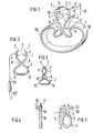
- FIG. 4shows the force application of a pair of pliers 19 on feet 12 of the spring of a clip projecting outwards.
- the pliers 19are provided with pliers tips 11 which can be inserted into corresponding engagement openings 14 in the feet 12 of the clip, which is not shown in detail here.
- the clipis designed omega-shaped according to FIG. 5.
- the feet 13are bent back in the direction of the clamp legs 1. This creates space for the form-fitting, aligned engagement of a blunt, head-like pliers end 15.
- the transition from the feet to the pliers endscan easily be designed so that there is a further rounding.
- a Hall generatorcan be attached to the inside of a bracket leg, with which movements relative to the earth's magnetic field can be detected.
- a Hall generatoris available under the type designation SAS 231 L from Siemens Aktiengesellschaft, Erlangen, Germany.
- SAS 231 Lfrom Siemens Aktiengesellschaft, Erlangen, Germany.
- a total of five leadsare required for such a Hall generator, which would take the place of the accelerometer 18, so that these leads for the supply voltage and the leads for the voltage to be derived can be realized.
- a graphic representation of these derivationswas made omitted for reasons of clarity. However, they emerge on the free side of the clamp leg 1.
- the angular position of the contact tips 21, 22 with respect to the longitudinal axis 23 of the probeis such that when the V-shaped spring 24 is compressed, they have a lower inclination to the longitudinal axis 23 than in the relaxed state.
- the dashed line 21 'shows the position of the spring and the contact tip in the tensioned state. In the relaxed state, the contact tips assume an almost vertical position with respect to the longitudinal axis 23.
- At least one of the contact tipscan be designed as an injection cannula.
- Thisnot only enables a hose line to be connected, but the injection cannula can also be used to insert a pH measuring electrode.
- a pH measuring electrodeis known from the publication “Innovation in Instrumentation” from World Prezision Instruments, Inc., New Haven Conn., USA, and is more specifically referred to there as Beetrode.
- Such a pH measuring electrodecan largely be guided in a contact tip designed as an injection cannula and secured against breaking off.
Landscapes
- Health & Medical Sciences (AREA)
- Life Sciences & Earth Sciences (AREA)
- Physics & Mathematics (AREA)
- General Health & Medical Sciences (AREA)
- Veterinary Medicine (AREA)
- Engineering & Computer Science (AREA)
- Biomedical Technology (AREA)
- Heart & Thoracic Surgery (AREA)
- Medical Informatics (AREA)
- Molecular Biology (AREA)
- Surgery (AREA)
- Animal Behavior & Ethology (AREA)
- Biophysics (AREA)
- Public Health (AREA)
- Pathology (AREA)
- Pediatric Medicine (AREA)
- Optics & Photonics (AREA)
- Cardiology (AREA)
- Pregnancy & Childbirth (AREA)
- Gynecology & Obstetrics (AREA)
- Reproductive Health (AREA)
- Spectroscopy & Molecular Physics (AREA)
- Measurement And Recording Of Electrical Phenomena And Electrical Characteristics Of The Living Body (AREA)
- Measurement Of The Respiration, Hearing Ability, Form, And Blood Characteristics Of Living Organisms (AREA)
Description
Translated fromGermanDie Erfindung bezieht sich auf eine physiologische Messsonde, insbesondere auf eine transzervikal mit Spitzen an der fetalen Kopfhaut fixierbare Vaginalelektrode für die Ableitung des fetalen EKG.The invention relates to a physiological measuring probe, in particular to a vaginal electrode which can be fixed transcervically with tips on the fetal scalp for the derivation of the fetal EKG.
Eine derartige Messsonde ist nach der US-A-4 080 961 bekannt. Die den Kontakt mit der Kopfhaut herstellenden, schräg nach vorne geneigten Spitzen befinden sich dabei an den Enden von Federschenkeln, die sich in zwei voneinander getrennten Ebenen aneinander vorbeischieben lassen. Sie können sich dabei zu einem in seinen Abmessungen nicht definierten Spalt schliessen, indem eine Hülse über die Schenkel der Feder geschoben wird. Beim Zurückschieben der Hülse entspannt sich die Feder, ohne durch Anschläge oder dergl. hierbei begrenzt zu sein. Die zunächst aneinander vorbeischerenden Spitzen definieren mithin auch im entlasteten Zustand der Feder keinen vorgegeben, festen Abstand voneinander.Such a measuring probe is known from US-A-4 080 961. The tips that make contact with the scalp and are inclined forward are located at the ends of spring legs that can be pushed past each other in two separate planes. You can close to a gap not defined in its dimensions by sliding a sleeve over the legs of the spring. When the sleeve is pushed back, the spring relaxes without being limited by stops or the like. The tips, which initially brush past each other, therefore do not define a predetermined, fixed distance from one another, even when the spring is released.
Derartige Messsonden sind ihrem grundsätzlichen Aufbau nach zur Ableitung des fetalen EKG während des gesamten Geburtsvorganges geeignet. Nach Edward H. Hon, Amer. J. Obstet. Gynec. Band 86, 1963, Seite 773, ist eine derartige Messsonde als Vaginalelektrode mit Kontaktspitzen ausgeführt, indem eine Wundklammer modifiziert und mittels einer Zange anwendbar gemacht wurde. Im Prinzip handelt es sich hierbei um eine Nadelelektrode. Sie setzt also ein verhältnismässig weites Eindringen der Spitze in die fetale Kopfhaut voraus. Vor Geburt des Kindes kann man eine derartige Klammer nur schwer wieder lösen. Darüber hinaus ist sie auch durch das Zu- und Aufbiegen für eine mehrfache Benutzung nicht geeignet, wie von H.W. Junge, 9, Geburtsh. u. Frauenheilk., 29.2, Seite 133, festgestellt wurde.The basic structure of such measuring probes is suitable for deriving the fetal EKG during the entire birth process. According to Edward H. Hon, Amer. J. Obstet. Gynec. Volume 86, 1963, page 773, such a measuring probe is designed as a vaginal electrode with contact tips by modifying a wound clip and making it usable with a pair of pliers. In principle, this is a needle electrode. It therefore requires a relatively wide penetration of the tip into the fetal scalp. It is difficult to release such a clip before the child is born. In addition, it is not suitable for multiple use due to the bending and bending, as by H.W. Boy, 9, birth u. Frauenheilk., 29.2, page 133.
Weiterhin sind federnde, nadelförmige Elektroden, die mit ihren Kontaktspitzen teilweise aneinander vorbeigleiten und dadurch auch Gewebeschäden verursachen können, bekannt nach Edward H. Hon, Yale Journal of Biology and Medicine, Band 32, April 1960. Die Kontaktspitzen dringen durch Schliessen einer Klammer in die Kopfhaut ein, wobei von der Klammer eine Ableitung ausgeht. Die Gegenelektrode endigt an einer von der genannten Klammer isolierten Stelle frei, so dass sich ein Kontakt mit der Mutter ergibt. Die Klammer kann auch nach Charles A. Hunter, Kenneth G. Lansford, Suzanne B. Knoebel und Robert J. Braunlin, Obstetrics and Gynecology, Band 16, 1960, Seite 567 durch eine Feder ersetzt sein. In diesem Falle ist die Feder in einem Führungsrohr verschieblich angeordnet, aus welchem lediglich die Vorderabschnitte mit den abgewinkelten Kontaktspitzen hervorragen. Zum Schliessen der Klammer bzw. zum Schliessen der Feder muss man in jedem Falle zunächst noch zusätzliche Kräfte aufbringen, die unter Geburtsbedingungen die Konzentration des Arztes unnötig beanspruchen.Furthermore, resilient, needle-shaped electrodes, which partially slide past one another with their contact tips and can therefore also cause tissue damage, are known from Edward H. Hon, Yale Journal of Biology and Medicine,
Demgegenüber liegt der Erfindung die Aufgabe zugrunde, eine physiologische Messsonde der einleitend bezeichneten Art dahingehend weiterzuentwickeln, dass sie einerseits eine wesentlich verbesserte Kontaktgabe ermöglicht, und dass andererseits das Hautgewebe bei der Applikation eine schonendere Behandlung erfährt. Vor allem soll die neue Messsonde auch die Möglichkeit der Anbringung weiterer Messelemente bieten, die mit der Applikationsfläche des Kopfes in Beziehung zu bringen sind, um den Geburtsvorgang nicht nur elektrokardiographisch, sondern auch durch sonstige Messungen überwachen zu können.In contrast, the object of the invention is to further develop a physiological measuring probe of the type described in the introduction in such a way that on the one hand it enables significantly improved contact and on the other hand the skin tissue is treated more gently during application. Above all, the new measuring probe should also offer the possibility of attaching further measuring elements that are related to the application area of the head, so that the birth process can be monitored not only electrocardiographically, but also by other measurements.
Diese Aufgabenstellung wird durch die Erfindung, wie sie in den Patentansprüchen gekennzeichnet ist, gelöst.This problem is solved by the invention as characterized in the claims.
Danach liegt der Erfindung das Prinzip zugrunde, den Abstand der Spitzen voneinander durch eine in den Entspannungszustand zu überführende Feder in der Applikationsstellung auf ein vorgebbares Mass zu fixieren und ein gegebenenfalls einzusetzendes, weiteres Messorgan mit definierter Kraft an die Hautfläche anzupressen.Accordingly, the invention is based on the principle of fixing the distance between the tips from one another in the application position to a predeterminable dimension by means of a spring to be brought into the relaxation state, and of pressing a further measuring element that may be used against the skin surface with a defined force.
Bei einer ersten grundlegenden Ausführungsform der Erfindung wird von den weitergehenden Merkmalen der US-A-4080961 Gebrauch gemacht, wonach sich an die Messsonde ein Ableitkabel anschliesst und sie als Klammer ausgebildet ist, deren Klammerschenkeln mit den nach innen gerichteten Spitzen versehen sind, deren Abstand voneinander kleiner als der Abstand der Klammerschenkel ist, und an die sich eine Feder anschliesst, deren gespanntem Zustand die Öffnungslage der Klammerschenkel entspricht, und die sich bei Entlastung der Feder in Richtung aufeinander bewegen.In a first basic embodiment of the invention, use is made of the further features of US-A-4080961, according to which a measuring cable is connected to the measuring probe and it is designed as a clip, the clip legs of which are provided with the inwardly directed tips, the spacing from one another is smaller than the distance between the clamp legs, and to which is connected a spring, the tensioned state of which corresponds to the opening position of the clamp legs, and which move towards one another when the spring is relieved.
Bei dieser ersten, grundlegenden Ausführungsform sieht die Erfindung die Lösung der Aufgabenstellung durch die Vorschläge der Patentansprüche 1 bis 9 vor. Demnach brauchen die Spitzen nicht notwendigerweise in die Kopfhaut einzudringen, denn sie dienen lediglich dem Halten. Der eigentliche Kontakt bildet sich durch Anlage der Kopfhautfalte an die Klammerschenkel.In this first, basic embodiment, the invention provides the solution to the problem by the proposals of
Der von den Klammerschenkeln nach Höhe und Breite vorgegebene Spalt besitzt dabei eine vorgebbare Weite, so dass der optimale Anpressdruck an die Kopfhaut gewährleistet wird. Letztere wird bei Anwendung von den Zähnen der geöffneten Klammerschenkel erfasst. Bei Entlasten der Feder schliessen sich die Klammerschenkel und ziehen dabei eine Hautfalte zwischen sich ein, die dann dem Druck der Schenkelflächen ausgesetzt ist. Die ausgedehnt flächige Anlage der Klammerschenkel bietet hervorragende Möglichkeiten, Geber von weiteren Messeinrichtungen mit den Klammerschenkeln zu verbinden, um sie gleichfalls auf die Kopfhaut zur Einwirkung zu bringen. Beispielsweise kann der eine Klammerschenkel eine schwache Lichtquelle und der andere Klammerschenkel eine Fotodiode aufnehmen, so dass Durchblutungsmessungen möglich sind. Die Klammerschenkel gestatten desweiteren die Anbringung von Elektroden für die Messung der Sauerstoffversorgung und die Anbringung von Beschleunigungsaufnehmern für die Überwachung der Geburtsmechanik. In allen Fällen ist die durch die erfindungsgemässe Messsonde ermöglichte, genau definierte Anlage der Klammerschenkelflächen an der zwischen ihnen eingezogenen Hautfalte von erheblichem Vorteil. Die Anwendung kann einerseits mittels einer Zange geschehen, indem die Zange an den Angriffsflächen der Feder anliegt und in gespanntem Zustand eingeführt wird. Bei Entlastung und Öffnung der Feder lässt sich die Zange zurückziehen. Umgekehrt ist eine Entfernung der Messsonde mittels der Zange gleichfalls leicht möglich. Darüber hinaus besteht aber auch die Möglichkeit, in an sich bekannter Weise einen verschiebbaren Kolben oder dergleichen zu verwenden, um die Feder aus gespanntem Zustand in den entspannten Zustand zu überführen. Die Feder ist zu diesem Zweck vorteilhaft in einer Hülse oder dergleichen angeordnet, aus der sie herausschiebbar ist.The gap specified by the staple legs in terms of height and width has a predefinable width, so that the optimal contact pressure on the scalp is guaranteed. The latter is grasped by the teeth of the opened staple legs when used. When the spring is released, the clamp legs close, drawing a skin fold between them, which is then exposed to the pressure of the leg surfaces. The extensive flat contact of the staple legs offers excellent options for connecting sensors from other measuring devices to the staple legs so that they can also act on the scalp. For example, one leg of the staple can accommodate a weak light source and the other leg of the staple can accommodate a photodiode, so that blood flow measurements are possible. The clamp legs also allow the attachment of electrodes for measuring the oxygen supply and the attachment of accelerometers for monitoring the birth mechanics. In all cases, the precisely defined contact of the clamp leg surfaces with the skin fold drawn between them, made possible by the measuring probe according to the invention, is of considerable advantage. The application can be done on the one hand by means of a pair of pliers, in that the pliers abut the contact surfaces of the spring and are inserted in a tensioned state. The pliers can be pulled back when the spring is released and opened. Conversely, removal of the measuring probe by means of the pliers is also easily possible. In addition, there is also the possibility, in a manner known per se, of using a displaceable piston or the like in order to transfer the spring from the tensioned state to the relaxed state. For this purpose, the spring is advantageously arranged in a sleeve or the like from which it can be pushed out.
Besonders zweckmässig ist die kreisringförmige Ausbildung der Feder, wobei dann die Spannung im ringförmigen Teil besteht, während die Klammerschenkel geradflächig verlaufen. Zwischen letzteren und der Feder können vorteilhaft gebogene Verbindungsabschnitte bestehen, die sich entlang einer in Richtung der Breite des Spaltes verlaufenden Linie berühren. Auf diese Weise wird ein Abrollpunkt geschaffen, so dass sich beim Zusammendrücken des kreisringförmigen Federteils die Klammerschenkel öffnen. In diesem Zustand werden die Zähne auf die zu ergreifende Haut aufgesetzt, woraufhin die Feder entspannt werden kann, was dann zu der bereits beschriebenen Aufnahme einer Hautfalte zwischen den Klammerschenkeln führt. Soweit die Verwendung einer Zange vorgesehen ist, werden die Kraftangriffsflächen der Feder für den Zangenangriff gestaltet, der formschlüssig oder kraftschlüssig sein kann.The ring-shaped design of the spring is particularly expedient, in which case the tension in the ring-shaped part exists while the clip legs run in a straight surface. Between the latter and the spring there can advantageously be curved connecting sections which touch along a line running in the direction of the width of the gap. In this way, a rolling point is created so that the clamp legs open when the annular spring part is compressed. In this state, the teeth are placed on the skin to be gripped, whereupon the spring can be relaxed, which then leads to the above-described absorption of a skin fold between the clamp legs. If the use of pliers is intended, the force application surfaces of the spring are designed for the forceps engagement, which can be form-fitting or non-positive.
In einer speziellen Ausführungsform der Erfindung ist die Klammer als solche Omega-förmig gestaltet, wobei dann die Kraftangriffsflächen an den nach aussen abstehenden Füssen der Schenkel bestehen. Dies führt dazu, dass man die Feder nicht zusammendrückt, sondern spreizt, um die Klammerschenkel zu öffnen. Die Füsse der Schenkel können dabei Eingriffsöffnungen für die Zangenspitzen besitzen. Andererseits lassen sich die Füsse auch in Richtung auf die Klammerschenkel zurückbiegen, so dass dann formschlüssig stumpfe, kopfartige Zangenenden zwischen die Klammerschenkel und die zurückgebogenen Füsse eingebracht werden können. Eine derartige Ausführungsform ist in besonderem Masse geeignet, um Verletzungen zu vermeiden.In a special embodiment of the invention, the clip is designed as such in an omega shape, in which case the force application surfaces then exist on the feet of the legs protruding outwards. This leads to the fact that one does not compress the spring, but spreads it to open the clamp legs. The feet of the legs can have engagement openings for the pliers tips. On the other hand, the feet can also be bent back in the direction of the staple legs, so that blunt, head-like pliers ends can then be inserted in a form-fitting manner between the staple legs and the bent-back feet. Such an embodiment is particularly suitable to avoid injuries.
Abweichend von der vorstehend beschriebenen Ausführungsform lässt sich die Klammer grundsätzlich auch U-förmig gestalten und mittels der Zangenenden spreizen. Bei dieser stark vereinfachten Ausführung kann man vor allem auch auf der Innenseite der Klammerschenkel verteilte Zähne vorsehen; desgleichen lässt sich auch nur ein Klammerschenkel endseitig als Spitze ausbilden, während der gegenüberliegende Klammerschenkel über seine Länge die erwähnten Zähne aufweist.Deviating from the embodiment described above, the clip can in principle also be designed in a U-shape and spread using the ends of the pliers. In this greatly simplified version, it is possible to provide teeth which are distributed on the inside of the clamp legs; Likewise, only one clip leg can be formed as a tip at the end, while the opposite clip leg has the teeth mentioned over its length.
Eine besondere gegen eine Verkantung der Feder geschützte Ausführungsform besteht darin, dass sich zwischen der Feder und den Klammerschenkeln Verbindungsabschnitte befinden, die einander durchdringen. Zu diesem Zweck ist einer der Verbindungsabschnitte geschlitzt und der andere, gegenüberliegende Verbindungsabschnitt auf die Breite des Schlitzes reduziert, wobei dann noch beide Verbindungsabschnitte im Durchdringungsbereich entgegengesetzt zur Feder gekrümmt sind. Die Vermeidung einer Verkantung gewährleistet bei diesen sowie bei den übrigen erfindungsgemässen Messsonden das genaue Gegenüberliegen der für die Messung massgeblichen Flächen unter Einschluss der eingezogenen Hautfalte.A special embodiment protected against tilting of the spring is that there are connecting sections between the spring and the clamp legs which penetrate one another. For this purpose, one of the connecting sections is slotted and the other, opposite connecting section is reduced to the width of the slot, with both connecting sections then being curved opposite to the spring in the penetration area. The avoidance of canting ensures that these and the other measuring probes according to the invention are exactly opposite of the areas relevant for the measurement, including the retracted skin fold.
Bei einer anderen, grundlegenden Ausführungsform der Erfindung wird von Merkmalen der US-A-4 080 961 Gebrauch gemacht, nach denen sich an die Messsonde Ableitungskabel anschliessen, wobei die Spitzen federnde, von der Längsachse der-Sonde schräg nach vorne geneigte, invasive Kontaktspitzen sind, die bei zunehmender Entspannung der auf sie einwirkenden Feder ihren Abstand voneinander bis in die Endlage verändern.In another basic embodiment of the invention of US-A-4, is made 080 961 use of features by which to connect it to the measuring probe lead wires with the tips of resilient, from the longitudinal axis of the- probe obliquely forwardly inclined, invasive contact tips are which change their distance from each other to the end position as the spring acting on them relaxes.
Bei dieser weiteren Ausführungsform schlägt die Erfindung zur Aufgabenlösung die Merkmale der Ansprüche 10 bis 17 vor. Danach vermögen die Kontaktspitzen unter Beibehaltung ihrer Ebene nur bis zu einer genau vorgegebenen Tiefe in die Kopfhaut einzudringen. Bei der bevorzugt mittels einer Zange vorgenommenen Applikation führt eine Entlastung der Zangendruckflächen ohne Einsatz weiterer manueller Kräfte dazu, dass die Kontaktspitzen in die Kopfhaut eindringen. Dabei besteht noch der weitere Vorteil, dass sich die Sonde mit geschlossenen Zangenspitzen einführen lässt, so dass eine minimale Ausdehnung besteht und die Anwendung auch bei nur leicht geöffnetem Muttermund möglich ist.In this further embodiment, the invention proposes the features of
Die vorgeschlagenen Kunststoffumhüllungsabschnitte sind nicht nur unter dem Gesichtspunkt eines Tiefenanschlages der Kontaktspitzen zweckmässig, sondern darüber hinaus auch wegen ihrer Isolationswirkung bei der Ableitung von Potentialen sowie zur Verbesserung der Ausbildung von Zangenflächen.The proposed plastic sheathing sections are useful not only from the point of view of a depth stop of the contact tips, but also because of their insulating effect in deriving potential and for improving the formation of pliers surfaces.
Zweckmässig werden die Kontaktspitzen nach aussen gerichtet ausgeführt, wobei sie sich endseitig bei Entspannung der Feder um etwa 10 mm zu spreizen vermögen, während sie eine Länge von weniger als 3 mm aufweisen. Bei Verwendung einer Spreizfeder ist deren Kraft zweckmässig so begrenzt, dass sie sich bei massvollem Längszug der Messsonde zu schliessen sucht und letztere herauszuziehen gestattet, um zum Beispiel die Geburt durch einen Kaiserschnitt auszuführen.The contact tips are expediently designed to face outwards, with the ends being able to expand by about 10 mm when the spring is released, while being less than 3 mm in length. When using a spreading spring, its force is expediently limited so that it tries to close when the measuring probe is pulled longitudinally and allows the latter to be pulled out, for example in order to carry out the birth through a caesarean section.
Von den Kontaktspitzen geht ein erstes Ableitungskabel für das fetale EKG aus, während von einem in der Nähe der Spitze der KunststoffUmhüllung befindlichen stumpfen Mutterkontakt ein zweites Ableitungskabel die Ableitung des Bezugspotentials ausgeht. Beide Ableitkabel können gemeinsam auch mit zusätzlichen Kabeln eingeführt werden, die beispielsweise zu Messelementen, wie temperaturveränderlichen Widerständen, führen, welche an der mit der Haut in Berührung gelangenden Seite des Umhüllungsabschnittes vorgesehen sind. Ferner lässt sich auch wenigstens eine der Kontaktspitzen als Injektionskanüle ausführen, von der ein Schlauch ausgeht, der gemeinsam mit den Ableitungskabeln geführt sein kann.A first lead for the fetal ECG extends from the contact tips, while a second lead leads the lead from a blunt mother contact located near the tip of the plastic sheath potential. Both discharge cables can also be introduced together with additional cables which lead, for example, to measuring elements, such as temperature-variable resistors, which are provided on the side of the covering section that comes into contact with the skin. Furthermore, at least one of the contact tips can also be designed as an injection cannula, from which a hose emerges, which can be guided together with the discharge cables.
Zur weiteren Veranschaulichung der Erfindung wird auf die sich auf Ausführungsbeispiele beziehenden Zeichnungen Bezug genommen. Darin zeigen, jeweils in schematischen Darstellungen:
- Fig. 1 eine erste Ausführungsform der Erfindung, bei welcher zur besseren Darstellung der erfindungsgemässen Merkmale eine isometrische Wiedergabe gewählt wurde,
- Fig. 2 und Fig. 3 weitere Ausführungsformen im Querschnitt bei Verwendung von Kreisringfedern,
- Fig. 4 eine Art des Eingriffs einer Zangenspitze in einen Fuss der Messsonde,
- Fig. 5 eine Omega-förmige Messsonde,
- Fig. 6 eine abweichende Ausführungsform der Erfindung mit einer als Spreizfeder ausgeführten Messsonde,
- Fig. 7 eine weitere Abwandlung der Messsonde mit einer Schraubenfeder, und
- Fig. 8 eine Messsonde mit einer W-förmigen Feder.
- 1 shows a first embodiment of the invention, in which an isometric representation has been chosen to better illustrate the features according to the invention,
- 2 and FIG. 3 further embodiments in cross section when using annular springs,
- 4 shows a type of engagement of a pliers tip in a foot of the measuring probe,
- 5 an omega-shaped measuring probe,
- 6 shows a different embodiment of the invention with a measuring probe designed as an expansion spring,
- 7 shows a further modification of the measuring probe with a helical spring, and
- 8 shows a measuring probe with a W-shaped spring.
Den Ausführungsformen der Fig. 1 bis 5 sind gemeinsam die Klammerschenkel 1, welche mit der Feder 2 in Verbindung stehen, für welche die Kraftangriffsflächen 10 vorgesehen sind. Weiter ist allen Ausführungsformen der Spalt 3 zwischen den Klammerschenkeln 1 gemeinsam.Common to the embodiments of FIGS. 1 to 5 are the
Wie vor allem Fig. 1 erkennen lässt, sind die Abmessungen des Spaltes 3 in allen Raumkoordinaten fixiert. Die Spaltweite 4 ist vom Spannungszustand der Feder abhängig. Sie wird bei gespanntem Zustand der Feder grösser, um bei Entspannung der Feder auf ein vorgebbares Mass zurückzugehen, welches der eingezogenen Hautfalte entspricht. Die Hautfalte wird auf der gesamten Breite 9 bis zur Höhe 6 in den Spalt 3 eingezogen. Die einander gegenüberliegenden Flächen der Klammerschenkel 1 sind dann im entlasteten Zustand der Feder unmittelbar an die Hautfläche angepresst, sofern auf ihnen nicht im Sinne der vorliegenden Erfindung weitere Geber von Messeinrichtungen angebracht sind, die dann an der Haut anliegen. Schematisch zeigt der linke Klammerschenkel der Fig. 1 einen aufgesetzten Beschleunigungsaufnehmer 18. Der Abstand der an den Enden der Klammerschenkel 1 vorgesehenen Zähne 7 voneinander ist stets kleiner als die Weite 4 des Spaltes 3, so dass die Hautfalte wirkungsvoll fixiert ist. Zwischen den Klammerschenkeln 1 und der Feder 2 bestehen bei den Ausführungsformen der Fig. 1 bis 3 gebogene Verbindungsabschnitte 8, deren Krümmung zu derjenigen der Feder 2 entgegengesetzt ist. Die Verbindungsabschnitte 8 berühren bei der Ausführungsform nach Fig. 1 und 2 einander, und zwar entlang einer sich in Richtung der Breite 9 des Spaltes 3 erstreckenden Linie 17. An dieser Berührungsstelle rollen die Verbindungsabschnitte 8 bei Belastung der Kraftangriffsflächen 10 aneinander ab und können damit die Klammerschenkel öffnen oder schliessen. Bei der Ausführungsform nach Fig. 3 durchdringen sich die Verbindungsabschnitte 8 in der bereits beschriebenen Weise, so dass es ebenfalls bei einer Druckbelastung der Kraftangriffsflächen 10 zu einer Öffnung des Spaltes 3 kommt.As can be seen above all in FIG. 1, the dimensions of the
Die Ausführungsform der Fig. 4 zeigt den Kraftangriff einer Zange 19 auf endseitig nach aussen abstehende Füsse 12 der Feder einer Klammer. Zu diesem Zweck ist die Zange 19 mit Zangenspitzen 11 versehen, die in entsprechende Eingriffsöffnungen 14 in den Füssen 12 der im übrigen hier nicht näher dargestellten Klammer einsetzbar sind.The embodiment of FIG. 4 shows the force application of a pair of
Die Klammer ist nach Fig. 5 Omega-förmig ausgeführt. In diesem Falle sind abweichend von der Ausgestaltung nach Fig. 4 die Füsse 13 in Richtung auf die Klammerschenkel 1 zurückgebogen. Hierdurch wird Raum für den formschlüssigen, fluchtenden Eingriff eines stumpfen, kopfartigen Zangenendes 15 geschaffen. Wie die Zeichnung zeigt, lässt sich der Übergang von den Füssen zu den Zangenenden leicht so gestalten, dass eine weitergehende Abrundung besteht.The clip is designed omega-shaped according to FIG. 5. In this case, deviating from the embodiment according to FIG. 4, the
Die Ausführungsformen gemäss den Fig. 1 bis 5 besitzen Ableitkabel, wie es der Einfachheit halber nur in Fig. 2 zeichnerisch wiedergegeben ist. Das Ableitkabel 20 ist an die Innenseite eines der beiden Klammerschenkel 1 angeschlossen. Im Anschluss an die Messsonde ist das Ableitkabel 20 durch einen blanken Metallzylinder isoliert geführt, an welch letzteren sich das weitere Ableitkabel 20' isoliert anschliesst. Auf diese Weise wird ein Bezugspotential geschaffen, welches in Berührung mit der Mutter steht.The embodiments according to FIGS. 1 to 5 have discharge cables, as is only shown in the drawing in FIG. 2 for the sake of simplicity. The
Neben dieser bei allen Ausführungsformen vorgesehenen Ableitung können, wie bereits zuvor erwähnt, ergänzende Geber weiterer Messeinrichtungen vorhanden sein, von denen Fig. 1 schematisch einen Beschleunigungsaufnehmer 18 wiedergibt. Anstelle eines derartigen Beschleunigungsaufnehmers 18 können insbesondere Elektroden für die transcutane Sauerstoffpartialdruckmessung vorhanden sein, wie sie aus der Druckschrift «Cutaneous Oxygen Monitoring in the Newborn», Paediatrician, Band 5, Nr. 5-6, 1976, Seite 342 wiedergegeben ist.In addition to this derivation provided in all of the embodiments, additional transmitters of further measuring devices, of which FIG. 1 schematically represents an
Desgleichen kann an der Innenseite eines Klammerschenkels ein Hall-Generator befestigt sein, mit dem Bewegungen relativ zum Magnetfeld der Erde erfasst werden können. Ein derartiger Hall-Generator wird unter der Typenbezeichnung SAS 231 L angeboten von der Firma Siemens Aktiengesellschaft, Erlangen, Deutschland. Man benötigt für einen derartigen Hall-Generator, der an die Stelle des Beschleunigungsaufnehmers 18 treten würde, insgesamt fünf Ableitungen, damit diese Zuleitungen für die Versorgungsspannung und die Ableitungen für die abzuleitende Spannung verwirklicht werden können. Auf eine zeichnerische Wiedergabe dieser Ableitungen wurde aus Gründen der Übersichtlichkeit verzichtet. Sie treten indes auf der freien Seite der Klammerschenkel 1 aus.Likewise, a Hall generator can be attached to the inside of a bracket leg, with which movements relative to the earth's magnetic field can be detected. Such a Hall generator is available under the type designation SAS 231 L from Siemens Aktiengesellschaft, Erlangen, Germany. A total of five leads are required for such a Hall generator, which would take the place of the
Bei einem Beschleunigungsaufnehmer würde man demgegenüber mit vier Leitungen auskommen. Eine geeignete Ausführung hat die Typenbezeichnung EGA-125-50D und wird von der Firma Entran International Fairfield, N.J., USA, geliefert.An accelerometer, on the other hand, would do with four lines. A suitable version has the type designation EGA-125-50D and is supplied by Entran International Fairfield, N.J., USA.
Mit nur drei Ableitungen würde man ein herkömmliches Mikrophon anschliessen können, wohingegen für eine fotooptische Einrichtung, bestehend aus einer Fotodiode und einem Empfänger, vier Ableitungen notwendig wären.A conventional microphone could be connected with only three leads, whereas four leads would be necessary for a photo-optical device consisting of a photodiode and a receiver.
Bei der Ausführungsform nach Fig. 6 schliessen sich an die V-förmig ausgeführte Feder 24 abgewinkelte Abschnitte 25, 26 an, die zu den Kontaktspitzen 21, 22 fortgesetzt sind. Die Winkelstellung der Kontaktspitzen 21, 22 zur Längsachse 23 der Sonde ist derart, dass sie in zusammengedrücktem Zustand der V-förmigen Feder 24 eine geringere Neigung zur Längsachse 23 aufweisen als im entspannten Zustand. Die gestrichelte Linie 21' zeigt die Lage der Feder und der Kontaktspitze im gespannten Zustand. Im entspannten Zustand nehmen die Kontaktspitzen eine nahezu senkrechte Stellung in Bezug auf die Längsachse 23 ein.In the embodiment according to FIG. 6,
Die V-förmige Kunststoffumhüllung 27 besitzt beidseitig Zangendruckflächen 28, 29, die mit Riffeln oder dergleichen griffiger gemacht werden können. Somit ist es möglich, die V-förmige Feder durch Schliessen der Zange geschlossen zu halten.The V-shaped plastic covering 27 has pliers pressure surfaces 28, 29 on both sides, which can be made more grippy with corrugations or the like. It is thus possible to keep the V-shaped spring closed by closing the pliers.
Neben den Kontaktspitzen 21, von denen ein gemeinschaftliches Ableitungskabel 31 ausgeht, ist noch eine stumpfe Elektrode 30 in Nähe der Spitze der Kunststoffumhüllung 27 vorgesehen, welche als Mutterelektrode geschaltet ist; von dieser geht das Ableitungskabel 32 aus.In addition to the
Die V-förmige Umhüllung 27 umfasst auch die abgewinkelten Abschnitte 25 und 26. An dieser Stelle besitzt die Kunststoffumhüllung Abschnitte 33 und 34, welche derart flach gestaltet sind, dass sie die Eindringtiefe der Kontaktspitzen 21, 22 begrenzen. Die Abschnitte 33 und 34, tragen je ein Messelement 35, von denen eines zum Beispiel ein NTC-Widerstand ist. Von ihnen gehen je ein Ableitungskabel 36 und 37 aus. Die Kontaktspitze 22 ist zusätzlich als eine Injektionskanüle ausgeführt. An diese schliesst sich ein hier nicht dargestellter Injektionsschlauch an. Wahlweise kann sie auch den NTC-Widerstand mit einem Ableitungskabel aufnehmen.The V-shaped
Bei der in Fig. 7 dargestellten Ausführungsform sind die gleichen Bezugszeichen für gleiche Teile wie in Fig. 6 angegeben. Die Kunststoffumhüllung 27 ist hierbei jedoch nicht V-förmig, sondern im Querschnitt etwa kreisförmig. In ihr sind je ein Ableitkabel 31 und 31' für die beiden Kontaktspitzen 21 und 22 isoliert geführt. Ausserdem verlaufen in ihr die beiden isoliert geführten Kabel 32 und 32' des Bezugspotentials, ausgehend von den stumpfen Elektroden 30, 30'. Im Innern der Kunststoffumhüllung 27 ist ein aus Kunststoff angeformter Zylinder 40 vorgesehen, der sich in Längsrichtung der Messsonde erstreckt, und der eine Schraubendruckfeder 39 aufnimmt. Die Vorderkante des Zylinders ist mit einer ringförmigen Schulter 41 ausgeführt, an welcher in der dargestellten Lage die Gegenschulter des Gehäuses eines weiteren Messelementes 42 anliegt. In dieser Lage wird das weitere Messelement 42 von der entspannten, im Freiraum 43 befindlichen Schraubendruckfeder 39 gehalten.In the embodiment shown in FIG. 7, the same reference numerals are given for the same parts as in FIG. 6. However, the plastic covering 27 is not V-shaped, but rather approximately circular in cross section. In each one
Somit befindet sich die Messsonde gemäss Fig. 7 gleichfalls im Applikationszustand. Für die vorherigen Zwecke der Einführung war das Messelement 42 in den Freiraum 43 unter Spannung der Schraubendruckfeder 39 zurückgeschoben, während die Kunststoffumhüllung 27 mittels einer Zange, die an den Zangendruckflächen 28 und 29 angriff, zusammengehalten wurde. Die Entlastung der Zangendruckflächen 28 und 29 führte sodann zum Vordrücken des Messelementes 42 bei gleichzeitiger Spreizung der Kontaktspitzen 21, 22.7 is also in the application state. For the previous purposes of the introduction, the measuring
Das weitere Messelement 42 steht also unter der Einwirkung der Feder 39, während es in Funktion ist. Dadurch ist ein besonders wirkungsvoller Hautkontakt gewährleistet. Es kann also nicht nur ein Mikrophon sein, sondern auch etwa ein Beschleunigungsaufnehmer oder ein Sensor zur Bestimmung der Raumkoordinaten bzw. ein Sensor für Reflexions- und Transmissionsmessungen. Die Transmission ist dann möglich, wenn sich die Kontaktspitzen 21, 22 unter der Haut gegenüber liegen. Diese Messungen sind für die laufende Überwachung von grossem Interesse, weil man hierdurch auf den Grad der Durchblutung und damit der akut veränderten Kreislaufsituation, wie zum Beispiel Zentralisation, schliessen kann. Lichtquellen und Fotoempfänger lassen sich im Bereich der Kontaktspitzen hierfür anordnen.The
Wie erwähnt, kann wenigstens eine der Kontaktspitzen als eine Injektionskanüle ausgeführt sein. Dies ermöglicht nicht nur den Anschluss einer Schlauchleitung, sondern man kann die Injektionskanüle auch benutzen, um eine pH-Messelektrode einzuführen. Eine derartige Messelektrode ist bekannt aus der Druckschrift «Innovation in Instrumentation» der Firma World Prezision Instruments, Inc., New Haven Conn., USA, und dort als Beetrode näher bezeichnet. Eine derartige pH-Messelektrode kann in einer als Injektionskanüle ausgeführten Kontaktspitze weitgehend geführt und gegen Abbrechen gesichert werden.As mentioned, at least one of the contact tips can be designed as an injection cannula. This not only enables a hose line to be connected, but the injection cannula can also be used to insert a pH measuring electrode. Such a measuring electrode is known from the publication “Innovation in Instrumentation” from World Prezision Instruments, Inc., New Haven Conn., USA, and is more specifically referred to there as Beetrode. Such a pH measuring electrode can largely be guided in a contact tip designed as an injection cannula and secured against breaking off.
Fig. 8 zeigt eine Anordnung, bei welcher sich die Kontaktspitzen 21 und 22 an den Enden einer etwa W-förmigen Feder befinden. Diese Darstellung ist im Zustand der Spannung wiedergegeben. Im Zustand der Entspannung spreizen sich die Kontaktspitzen 21 und 22 auseinander und nehmen eine durch den Entspannungszustand der Feder vorgegebene, fixierte Stellung in der Kopfhaut ein. Dabei wird der Innenabschnitt 43 der Feder in Richtung auf die Kopfhaut gedrückt und presst dabei das Messelement 42 an die Kopfhaut an. In diesem Falle ist es auch möglich, anstelle des Messelementes einen Bolzen zu verwenden, der nur die Funktion übernimmt, einen zuverlässigen Anpressungszustand herbeizuführen.Fig. 8 shows an arrangement in which the
Claims (17)
Priority Applications (1)
| Application Number | Priority Date | Filing Date | Title |
|---|---|---|---|
| AT84112197TATE37137T1 (en) | 1983-10-13 | 1984-10-11 | PHYSIOLOGICAL PROBE. |
Applications Claiming Priority (4)
| Application Number | Priority Date | Filing Date | Title |
|---|---|---|---|
| DE3337188 | 1983-10-13 | ||
| DE19833337188DE3337188A1 (en) | 1983-10-13 | 1983-10-13 | Physiological invasive measurement probe |
| DE3434657 | 1984-09-21 | ||
| DE19843434657DE3434657A1 (en) | 1984-09-21 | 1984-09-21 | Physiological measuring probe |
Publications (3)
| Publication Number | Publication Date |
|---|---|
| EP0137500A2 EP0137500A2 (en) | 1985-04-17 |
| EP0137500A3 EP0137500A3 (en) | 1985-06-05 |
| EP0137500B1true EP0137500B1 (en) | 1988-09-14 |
Family
ID=25814812
Family Applications (1)
| Application Number | Title | Priority Date | Filing Date |
|---|---|---|---|
| EP84112197AExpiredEP0137500B1 (en) | 1983-10-13 | 1984-10-11 | Physiological sensor |
Country Status (3)
| Country | Link |
|---|---|
| US (1) | US4644956A (en) |
| EP (1) | EP0137500B1 (en) |
| DE (1) | DE3473989D1 (en) |
Families Citing this family (61)
| Publication number | Priority date | Publication date | Assignee | Title |
|---|---|---|---|---|
| US4632120A (en)* | 1985-04-25 | 1986-12-30 | Westinghouse Electric Corp. | Subkeratinous electroencephalographic probe |
| WO1991018549A1 (en)* | 1990-05-29 | 1991-12-12 | Yue Samuel K | Fetal probe apparatus |
| US5833622A (en)* | 1994-04-04 | 1998-11-10 | Graphic Controls Corporation | Non-invasive fetal probe having improved mechanical and electrical properties |
| US5474065A (en)* | 1994-04-04 | 1995-12-12 | Graphic Controls Corporation | Non-invasive fetal probe |
| US5593429A (en)* | 1994-06-28 | 1997-01-14 | Cadwell Industries, Inc. | Needle electrode with depth of penetration limiter |
| US6391048B1 (en)* | 2000-01-05 | 2002-05-21 | Integrated Vascular Systems, Inc. | Integrated vascular device with puncture site closure component and sealant and methods of use |
| US6942674B2 (en) | 2000-01-05 | 2005-09-13 | Integrated Vascular Systems, Inc. | Apparatus and methods for delivering a closure device |
| US6461364B1 (en)* | 2000-01-05 | 2002-10-08 | Integrated Vascular Systems, Inc. | Vascular sheath with bioabsorbable puncture site closure apparatus and methods of use |
| US7842068B2 (en)* | 2000-12-07 | 2010-11-30 | Integrated Vascular Systems, Inc. | Apparatus and methods for providing tactile feedback while delivering a closure device |
| US9579091B2 (en)* | 2000-01-05 | 2017-02-28 | Integrated Vascular Systems, Inc. | Closure system and methods of use |
| US8758400B2 (en) | 2000-01-05 | 2014-06-24 | Integrated Vascular Systems, Inc. | Closure system and methods of use |
| DE60144328D1 (en)* | 2000-09-08 | 2011-05-12 | Abbott Vascular Inc | Surgical clamp |
| US6626918B1 (en) | 2000-10-06 | 2003-09-30 | Medical Technology Group | Apparatus and methods for positioning a vascular sheath |
| US7806904B2 (en)* | 2000-12-07 | 2010-10-05 | Integrated Vascular Systems, Inc. | Closure device |
| US7905900B2 (en)* | 2003-01-30 | 2011-03-15 | Integrated Vascular Systems, Inc. | Clip applier and methods of use |
| US8690910B2 (en) | 2000-12-07 | 2014-04-08 | Integrated Vascular Systems, Inc. | Closure device and methods for making and using them |
| US6695867B2 (en) | 2002-02-21 | 2004-02-24 | Integrated Vascular Systems, Inc. | Plunger apparatus and methods for delivering a closure device |
| US7211101B2 (en)* | 2000-12-07 | 2007-05-01 | Abbott Vascular Devices | Methods for manufacturing a clip and clip |
| US6623510B2 (en) | 2000-12-07 | 2003-09-23 | Integrated Vascular Systems, Inc. | Closure device and methods for making and using them |
| IES20010547A2 (en)* | 2001-06-07 | 2002-12-11 | Christy Cummins | Surgical Staple |
| IES20030424A2 (en)* | 2002-06-04 | 2003-12-10 | Robert Stevenson | Blood vessel closure clip and delivery device |
| US7416556B2 (en)* | 2002-06-06 | 2008-08-26 | Abbott Laboratories | Stop-cock suture clamping system |
| US20030229377A1 (en)* | 2002-06-10 | 2003-12-11 | Thomas Tong | Tube and rod suture clamping system |
| US7108710B2 (en)* | 2002-11-26 | 2006-09-19 | Abbott Laboratories | Multi-element biased suture clip |
| US8202293B2 (en) | 2003-01-30 | 2012-06-19 | Integrated Vascular Systems, Inc. | Clip applier and methods of use |
| US7857828B2 (en)* | 2003-01-30 | 2010-12-28 | Integrated Vascular Systems, Inc. | Clip applier and methods of use |
| US8905937B2 (en)* | 2009-02-26 | 2014-12-09 | Integrated Vascular Systems, Inc. | Methods and apparatus for locating a surface of a body lumen |
| US8398656B2 (en) | 2003-01-30 | 2013-03-19 | Integrated Vascular Systems, Inc. | Clip applier and methods of use |
| IES20040368A2 (en)* | 2004-05-25 | 2005-11-30 | James E Coleman | Surgical stapler |
| US8926633B2 (en)* | 2005-06-24 | 2015-01-06 | Abbott Laboratories | Apparatus and method for delivering a closure element |
| US8313497B2 (en)* | 2005-07-01 | 2012-11-20 | Abbott Laboratories | Clip applier and methods of use |
| USD611144S1 (en) | 2006-06-28 | 2010-03-02 | Abbott Laboratories | Apparatus for delivering a closure element |
| US8556930B2 (en) | 2006-06-28 | 2013-10-15 | Abbott Laboratories | Vessel closure device |
| JP5226776B2 (en)* | 2007-05-22 | 2013-07-03 | パーシスト ディベロップメント コーポレイション | EEG electrode quick press method and apparatus |
| US8694070B2 (en) | 2007-05-22 | 2014-04-08 | Persyst Development Corporation | Electrode applicator for quick press on EEG electrode |
| US8893947B2 (en)* | 2007-12-17 | 2014-11-25 | Abbott Laboratories | Clip applier and methods of use |
| US7841502B2 (en)* | 2007-12-18 | 2010-11-30 | Abbott Laboratories | Modular clip applier |
| US9282965B2 (en) | 2008-05-16 | 2016-03-15 | Abbott Laboratories | Apparatus and methods for engaging tissue |
| US8398676B2 (en) | 2008-10-30 | 2013-03-19 | Abbott Vascular Inc. | Closure device |
| US9414820B2 (en) | 2009-01-09 | 2016-08-16 | Abbott Vascular Inc. | Closure devices, systems, and methods |
| US9486191B2 (en) | 2009-01-09 | 2016-11-08 | Abbott Vascular, Inc. | Closure devices |
| US9173644B2 (en) | 2009-01-09 | 2015-11-03 | Abbott Vascular Inc. | Closure devices, systems, and methods |
| US20100179589A1 (en) | 2009-01-09 | 2010-07-15 | Abbott Vascular Inc. | Rapidly eroding anchor |
| US20100185234A1 (en) | 2009-01-16 | 2010-07-22 | Abbott Vascular Inc. | Closure devices, systems, and methods |
| US20110029025A1 (en)* | 2009-07-31 | 2011-02-03 | Medoff Robert J | Locking pin plate assembly adapted for fracture fixation |
| US20110054492A1 (en) | 2009-08-26 | 2011-03-03 | Abbott Laboratories | Medical device for repairing a fistula |
| US8666484B2 (en) | 2011-11-25 | 2014-03-04 | Persyst Development Corporation | Method and system for displaying EEG data |
| US9055927B2 (en) | 2011-11-25 | 2015-06-16 | Persyst Development Corporation | User interface for artifact removal in an EEG |
| CN104039221B (en) | 2011-11-26 | 2016-03-16 | 珀西斯特发展公司 | Methods and systems for detecting and removing EEG artifacts |
| US9332976B2 (en) | 2011-11-30 | 2016-05-10 | Abbott Cardiovascular Systems, Inc. | Tissue closure device |
| DE102012105221B4 (en)* | 2012-06-15 | 2015-02-19 | Franke Maschinenbau Medingen GmbH | Mounting device for elastic clamps |
| US9364209B2 (en) | 2012-12-21 | 2016-06-14 | Abbott Cardiovascular Systems, Inc. | Articulating suturing device |
| US10929753B1 (en) | 2014-01-20 | 2021-02-23 | Persyst Development Corporation | System and method for generating a probability value for an event |
| CN105322308B (en)* | 2014-07-31 | 2017-12-05 | 常州靓宇焊割有限公司 | Early warning electrode holder |
| DE102014113158A1 (en)* | 2014-09-12 | 2016-03-17 | Dr. Langer Medical Gmbh | lead-out |
| KR102403492B1 (en)* | 2014-10-30 | 2022-06-02 | 주식회사 인바디 | Electrode for measuring living body signal |
| US10117593B2 (en)* | 2016-08-04 | 2018-11-06 | Zentan Technology Co., Ltd. | Physiological signal detection clamp |
| CN106353488B (en)* | 2016-09-23 | 2023-05-30 | 遵义医学院 | Physiological experiment muscle groove with fixing function |
| US11457855B2 (en) | 2018-03-12 | 2022-10-04 | Persyst Development Corporation | Method and system for utilizing empirical null hypothesis for a biological time series |
| US11219416B2 (en) | 2018-03-12 | 2022-01-11 | Persyst Development Corporation | Graphically displaying evoked potentials |
| WO2021012075A1 (en)* | 2019-07-19 | 2021-01-28 | Medtrum Technologies Inc. | Integrated drug infusion device |
Family Cites Families (12)
| Publication number | Priority date | Publication date | Assignee | Title |
|---|---|---|---|---|
| US2611368A (en)* | 1950-01-10 | 1952-09-23 | Louis J Pecora | German silver electrocardiograph contact electrode |
| US3543760A (en)* | 1968-03-11 | 1970-12-01 | Medical Plastic Inc | Disposable ground plate electrode |
| US3750650A (en)* | 1970-12-15 | 1973-08-07 | Hewlett Packard Gmbh | Double spiral electrode for intra-cavity attachment |
| DE2309749B2 (en)* | 1973-02-27 | 1978-05-24 | Siegfried Dr.Med. Dipl.-Ing. Dipl.-Wirtsch.-Ing. Lehr | Electrode for medical purposes |
| BR7408329D0 (en)* | 1973-10-15 | 1975-08-26 | Medtronic Inc | IMPLANTABLE BODY ELECTRODE LIDE IMPLANTABLE IN BODY AND LEADS HOLDER SYSTEM |
| CA1045685A (en)* | 1974-01-02 | 1979-01-02 | Archibald W. Diack | Cardiac resuscitator and monitoring apparatus |
| US3999555A (en)* | 1975-10-28 | 1976-12-28 | Medtronic, Inc. | Atrial pinch on lead and insertion tool |
| DE2619471A1 (en)* | 1976-05-03 | 1977-11-24 | Albert Prof Dr Huch | Intra-uterine surface temp. measuring probe - is made from a probe material of low thermal conductivity |
| AR216293A1 (en)* | 1976-12-02 | 1979-12-14 | Leon De Pedro F | SELF-FIXING TOOTH ELECTRODE AND A GRIPPER FOR ITS MANEUVERING |
| US4080961A (en)* | 1976-12-22 | 1978-03-28 | Eaton Crosby J | Fetus scalp electrode instrument |
| US4254764A (en)* | 1979-03-01 | 1981-03-10 | Neward Theodore C | Clip electrode |
| US4680961A (en)* | 1986-01-27 | 1987-07-21 | Grauman R J | System and method for ice movement detection in determination of ice breakup |
- 1984
- 1984-10-11EPEP84112197Apatent/EP0137500B1/ennot_activeExpired
- 1984-10-11DEDE8484112197Tpatent/DE3473989D1/ennot_activeExpired
- 1984-10-15USUS06/661,236patent/US4644956A/ennot_activeExpired - Lifetime
Also Published As
| Publication number | Publication date |
|---|---|
| EP0137500A2 (en) | 1985-04-17 |
| EP0137500A3 (en) | 1985-06-05 |
| DE3473989D1 (en) | 1988-10-20 |
| US4644956A (en) | 1987-02-24 |
Similar Documents
| Publication | Publication Date | Title |
|---|---|---|
| EP0137500B1 (en) | Physiological sensor | |
| DE69330038T2 (en) | Instrument with improved contact between the fetus and probe | |
| DE2506872C3 (en) | Apparatus for screwing the uninsulated portion of an electrode assembly into body tissue | |
| DE3616616C2 (en) | ||
| DE69720669T2 (en) | biopsy device | |
| DE3445102C1 (en) | Electrode with a plug for an external pacemaker or ECG monitor | |
| DE3877712T2 (en) | CATHETER FOR ENDOCARDIAL BIOPSY AND FOR DETECTING A STARTING POINT OF CHAMBER-RELATED ARRHYTHMIA. | |
| DE3703458C2 (en) | ||
| DE69316740T2 (en) | TROCAR DEVICE WITH RETRACTABLE TIP | |
| DE69205980T2 (en) | PERIODICAL HEAD. | |
| DE69313283T2 (en) | MEDICAL DEVICE | |
| DE69124516T2 (en) | catheter | |
| DE2730691A1 (en) | CLIP AND DEVICE FOR YOUR ARRANGEMENT | |
| DE112016005391T5 (en) | CONNECTION STRUCTURE AND CONNECTION METHOD | |
| DE2309749B2 (en) | Electrode for medical purposes | |
| DE2605637A1 (en) | SURGICAL ELECTRODE | |
| DE1766737B2 (en) | Intrauterine contraceptive pad | |
| DE112008003820T5 (en) | One-body Lancet and Painless Blood Collection Device | |
| DE2830412A1 (en) | Foetal detector fitting instrument - draws tissue inside suction cup containing detectors and permits attachment of instruments | |
| DE4108518A1 (en) | HEART PACEMAKER | |
| DE2929233A1 (en) | DEVICE FOR FORMING A TISSUE TUNNEL AND / OR FOR POSITIONING A PIPE IN BODY TISSUE | |
| DE10354830B4 (en) | High frequency cutter | |
| DE2848483B2 (en) | Tissue extraction device | |
| DE4331304B4 (en) | Medical-surgical sensor arrangement | |
| DE3523733C2 (en) | Vascular clamp |
Legal Events
| Date | Code | Title | Description |
|---|---|---|---|
| PUAI | Public reference made under article 153(3) epc to a published international application that has entered the european phase | Free format text:ORIGINAL CODE: 0009012 | |
| PUAL | Search report despatched | Free format text:ORIGINAL CODE: 0009013 | |
| AK | Designated contracting states | Designated state(s):AT BE CH DE FR GB IT LI LU NL SE | |
| AK | Designated contracting states | Designated state(s):AT BE CH DE FR GB IT LI LU NL SE | |
| RTI1 | Title (correction) | ||
| 17P | Request for examination filed | Effective date:19851107 | |
| 17Q | First examination report despatched | Effective date:19870114 | |
| GRAA | (expected) grant | Free format text:ORIGINAL CODE: 0009210 | |
| AK | Designated contracting states | Kind code of ref document:B1 Designated state(s):AT BE CH DE FR GB IT LI LU NL SE | |
| PG25 | Lapsed in a contracting state [announced via postgrant information from national office to epo] | Ref country code:NL Effective date:19880914 Ref country code:IT Free format text:LAPSE BECAUSE OF FAILURE TO SUBMIT A TRANSLATION OF THE DESCRIPTION OR TO PAY THE FEE WITHIN THE PRESCRIBED TIME-LIMIT;WARNING: LAPSES OF ITALIAN PATENTS WITH EFFECTIVE DATE BEFORE 2007 MAY HAVE OCCURRED AT ANY TIME BEFORE 2007. THE CORRECT EFFECTIVE DATE MAY BE DIFFERENT FROM THE ONE RECORDED. Effective date:19880914 | |
| REF | Corresponds to: | Ref document number:37137 Country of ref document:AT Date of ref document:19880915 Kind code of ref document:T | |
| PG25 | Lapsed in a contracting state [announced via postgrant information from national office to epo] | Ref country code:AT Effective date:19881011 | |
| REF | Corresponds to: | Ref document number:3473989 Country of ref document:DE Date of ref document:19881020 | |
| GBT | Gb: translation of ep patent filed (gb section 77(6)(a)/1977) | ||
| ET | Fr: translation filed | ||
| NLV1 | Nl: lapsed or annulled due to failure to fulfill the requirements of art. 29p and 29m of the patents act | ||
| PLBE | No opposition filed within time limit | Free format text:ORIGINAL CODE: 0009261 | |
| STAA | Information on the status of an ep patent application or granted ep patent | Free format text:STATUS: NO OPPOSITION FILED WITHIN TIME LIMIT | |
| 26N | No opposition filed | ||
| PGFP | Annual fee paid to national office [announced via postgrant information from national office to epo] | Ref country code:FR Payment date:19921015 Year of fee payment:9 | |
| PGFP | Annual fee paid to national office [announced via postgrant information from national office to epo] | Ref country code:SE Payment date:19921023 Year of fee payment:9 Ref country code:LU Payment date:19921023 Year of fee payment:9 | |
| PGFP | Annual fee paid to national office [announced via postgrant information from national office to epo] | Ref country code:GB Payment date:19921028 Year of fee payment:9 | |
| PGFP | Annual fee paid to national office [announced via postgrant information from national office to epo] | Ref country code:BE Payment date:19921103 Year of fee payment:9 | |
| PGFP | Annual fee paid to national office [announced via postgrant information from national office to epo] | Ref country code:CH Payment date:19921118 Year of fee payment:9 | |
| EPTA | Lu: last paid annual fee | ||
| PG25 | Lapsed in a contracting state [announced via postgrant information from national office to epo] | Ref country code:LU Free format text:LAPSE BECAUSE OF NON-PAYMENT OF DUE FEES Effective date:19931011 Ref country code:GB Effective date:19931011 | |
| PG25 | Lapsed in a contracting state [announced via postgrant information from national office to epo] | Ref country code:SE Effective date:19931012 | |
| PG25 | Lapsed in a contracting state [announced via postgrant information from national office to epo] | Ref country code:LI Effective date:19931031 Ref country code:CH Effective date:19931031 Ref country code:BE Effective date:19931031 | |
| BERE | Be: lapsed | Owner name:MORGENSTERN JURGEN Effective date:19931031 | |
| GBPC | Gb: european patent ceased through non-payment of renewal fee | Effective date:19931011 | |
| PG25 | Lapsed in a contracting state [announced via postgrant information from national office to epo] | Ref country code:FR Effective date:19940630 | |
| REG | Reference to a national code | Ref country code:CH Ref legal event code:PL | |
| REG | Reference to a national code | Ref country code:FR Ref legal event code:ST | |
| EUG | Se: european patent has lapsed | Ref document number:84112197.3 Effective date:19940510 | |
| PGFP | Annual fee paid to national office [announced via postgrant information from national office to epo] | Ref country code:DE Payment date:19961206 Year of fee payment:13 | |
| PG25 | Lapsed in a contracting state [announced via postgrant information from national office to epo] | Ref country code:DE Free format text:LAPSE BECAUSE OF NON-PAYMENT OF DUE FEES Effective date:19980701 |