EP0130357B1 - Electro-magnetic alignment assemblies - Google Patents
Electro-magnetic alignment assembliesDownload PDFInfo
- Publication number
- EP0130357B1 EP0130357B1EP84106001AEP84106001AEP0130357B1EP 0130357 B1EP0130357 B1EP 0130357B1EP 84106001 AEP84106001 AEP 84106001AEP 84106001 AEP84106001 AEP 84106001AEP 0130357 B1EP0130357 B1EP 0130357B1
- Authority
- EP
- European Patent Office
- Prior art keywords
- magnetic circuit
- magnetic
- coil assembly
- electro
- respect
- Prior art date
- Legal status (The legal status is an assumption and is not a legal conclusion. Google has not performed a legal analysis and makes no representation as to the accuracy of the status listed.)
- Expired
Links
- 230000000712assemblyEffects0.000titleclaimsdescription23
- 238000000429assemblyMethods0.000titleclaimsdescription23
- 239000012530fluidSubstances0.000claimsdescription2
- XEEYBQQBJWHFJM-UHFFFAOYSA-NIronChemical compound[Fe]XEEYBQQBJWHFJM-UHFFFAOYSA-N0.000description22
- 229910052742ironInorganic materials0.000description11
- 230000004907fluxEffects0.000description5
- 239000012528membraneSubstances0.000description2
- XAGFODPZIPBFFR-UHFFFAOYSA-NaluminiumChemical compound[Al]XAGFODPZIPBFFR-UHFFFAOYSA-N0.000description1
- 229910052782aluminiumInorganic materials0.000description1
- 230000005284excitationEffects0.000description1
- 238000001393microlithographyMethods0.000description1
- 230000004048modificationEffects0.000description1
- 238000012986modificationMethods0.000description1
Images

Classifications
- G—PHYSICS
- G03—PHOTOGRAPHY; CINEMATOGRAPHY; ANALOGOUS TECHNIQUES USING WAVES OTHER THAN OPTICAL WAVES; ELECTROGRAPHY; HOLOGRAPHY
- G03F—PHOTOMECHANICAL PRODUCTION OF TEXTURED OR PATTERNED SURFACES, e.g. FOR PRINTING, FOR PROCESSING OF SEMICONDUCTOR DEVICES; MATERIALS THEREFOR; ORIGINALS THEREFOR; APPARATUS SPECIALLY ADAPTED THEREFOR
- G03F7/00—Photomechanical, e.g. photolithographic, production of textured or patterned surfaces, e.g. printing surfaces; Materials therefor, e.g. comprising photoresists; Apparatus specially adapted therefor
- G03F7/70—Microphotolithographic exposure; Apparatus therefor
- G03F7/70691—Handling of masks or workpieces
- G03F7/70716—Stages
- H—ELECTRICITY
- H02—GENERATION; CONVERSION OR DISTRIBUTION OF ELECTRIC POWER
- H02K—DYNAMO-ELECTRIC MACHINES
- H02K41/00—Propulsion systems in which a rigid body is moved along a path due to dynamo-electric interaction between the body and a magnetic field travelling along the path
- H02K41/02—Linear motors; Sectional motors
- H02K41/03—Synchronous motors; Motors moving step by step; Reluctance motors
- H02K41/031—Synchronous motors; Motors moving step by step; Reluctance motors of the permanent magnet type
- H—ELECTRICITY
- H02—GENERATION; CONVERSION OR DISTRIBUTION OF ELECTRIC POWER
- H02K—DYNAMO-ELECTRIC MACHINES
- H02K2201/00—Specific aspects not provided for in the other groups of this subclass relating to the magnetic circuits
- H02K2201/18—Machines moving with multiple degrees of freedom
Definitions
- This inventionrelates to an electro-magnetic alignment apparatus comprising, a first magnetic circuit having a plurality of elements including a first magnet element; a second magnetic circuit having a plurality of elements including a second magnet element disposed in spaced relationship with respect to said first magnetic circuit; a movable structural component, means for mounting an object on said component.
- the inventionrelates more particularly, to an electro-magnetic alignment apparatus which is particularly adapted, among other possible uses, for use in aligning the wafer in a microlithography system.
- a second frameis mounted within the first frame with the aid of two further membranes such that the second frame may be moved in a second direction along the Y-axis.
- At least one further coil assemblyis attached to the second frame and the said coil assembly passes the magnetic field of at least one magnet.
- means for mounting an objectare rotatably mounted on the second frame and are rotated with the aid of several electrostriction elements about a Z-axis perpendicular to the plane unfolded by the other two directions of the X-axis and Y-axis.
- each magnetic circuitbeing fixedly attached to said movable structural component; a first current carrying coil assembly being mounted in said first magnetic circuit; a second current carrying coil assembly being mounted in said first magnetic circuit, said first and said second coil assemblies being mounted at an angle with respect to each other; a third current carrying coil assembly being mounted in said second magnetic circuit; a fourth current carrying coil assembly being mounted in said second magnetic circuit, said third and fourth coil assemblies being mounted at an angle with respect to each other; and controller means for controlling the flow and direction of current through said coil assemblies, respectively being provided.
- the one element of each magnetic circuit attached to the movable structural componentis the magnet element of its respective circuit.
- the first and second current carrying coil assembliesare arranged such that their coils are wound substantially orthogonally with respect to each other, and the third and fourth coil assemblies are arranged such that their coils are wound substantially orthogonally with respect to each other.
- the first and third coil assembliesare arranged such that their coils are wound substantially in parallel with respect to each other, and the second and fourth coil assemblies are arranged such that their coils are wound substantially in parallel with respect to each other.
- the electro-magnetic alignment apparatuscomprises a fifth current carrying coil assembly mounted in said first magnetic circuit in spaced relationship with respect to said first coil assembly and substantially in parallel thereto; a . sixth current carrying coil assembly mounted in said first magnetic circuit in spaced relationship with respect to said second coil assembly and substantially in parallel thereto; a seventh current carrying coil assembly mounted in said second magnetic circuit in spaced relationship with respect to said third coil assembly and substantially in parallel thereto; and an eighth current carrying coil assembly mounted in said second magnetic circuit in spaced relationship with respect to said fourth coil assembly and substantially in parallel thereto.
- a plurality of sensor meansare provided for sensing the position of the movable structural component, and said sensor means acts as one input to the controller means.
- each of said plurality of elements forming said magnetic circuitsinclude an upper plate, a bottom plate spaced from said upper plate, and a side plate interconnecting the upper and bottom plates, said one element of each magnetic circuit being mounted between said upper and bottom plates.
- the movable structural component and said one element of each magnetic circuitare supported by fluid film bearings.
- the electro-magnetic alignment apparatuscomprises a first plurality of elements, including a first magnetic element 10, forming a first magnetic circuit indicated at 12, a second plurality of elements, including a second magnet element 14, forming a second magnetic circuit indicated at 16, and a movable structural component indicated at 18.
- the movable structural component 18includes means for mounting an object, such as a wafer 20 for example, thereon.
- the first plurality of elements for forming the first magnetic circuit 12includes an iron upper plate 22, an iron bottom plate 24 and a side plate, which in the embodiment of Fig. 1 is the first magnet element 10.
- This magnet element 10is a powerful permanent magnet and also serves to connect the upper and bottom plates.
- the second plurality of elements for forming the second magnetic circuit. 16includes an iron upper plate 26, an iron bottom plate 28 and a side plate, which in the embodiment of Fig. 1 is the second magnet element 14.
- This magnet element 14, like the magnet element 10is a powerful permanent magnet and serves to connect the upper and bottom plates.
- One element of the first magnetic circuit 12is fixedly attached to the movable structural component 18. In the embodiment of Fig. 1, this one element is an iron slug 30, which is movable between the upper plate 22 and the bottom plate 24.
- one element of the second magnetic circuit 16is fixedly attached to the movable structural component 18 which, in the embodiment of Fig. 1, is iron slug 32, that is movable between the upper plate 26 and the bottom plate 28.
- the first magnetic circuit 12has a first current carrying coil assembly 34, and a second current carrying coil assembly 36 mounted at an angle with respect to the first coil assembly. In the embodiment of Fig. 1, these two current carrying coil assemblies are disposed orthogonally with respect to each other.
- the second magnetic circuit 16has a third current carrying coil assembly 38, which is parallel to the first coil assembly 34, and a fourth current carrying coil assembly 40 mounted at an angle with respect to the third coil assembly.
- the third coil assembly 38is orthogonally disposed with respect to the fourth coil assembly 40.
- FIG. 1shows, in the first magnetic circuit 12, a fifth current carrying coil assembly 42, which is parallel to the first coil assembly 34 and a sixth current carrying coil assembly 44 which is parallel to the second coil assembly 36 and perpendicular to the fifth coil assembly 42.
- a seventh current carrying coil assembly 46is mounted parallel to the third coil assembly 38
- an eighth current carrying coil assembly 48is mounted parallel to the fourth coil assembly 40 and perpendicular to the seventh coil assembly 46.
- the first coil assembly 34is provided with a first lead 50 and a second lead 52, while the second to the eighth coil assemblies are provided with leads 54, 56, 58, 60, 62, 64, 66, 68, 70, 72, 74, 76, 78 and 80, respectively.
- the electrical current supplied to each of the leadsis controlled by a controller 82, as will be discussed more fully hereinafter.
- the movable structural component 18is mounted for movement with respect to the first and second magnetic circuits 12 and 14 by any suitable bearing means such as, for example, an air bearing mounted between the iron slug 30 and the bottom plate 24 and an air bearing mounted between the iron slug 32 and the bottom plate 28. Air is supplied to the air bearings by means of a piping system 84, provided for the purpose.
- the movable structural component 18may be desirable to fabricate the movable structural component 18 with an aluminum honeycomb structure to provide structural strength at minimum weight, as indicated at 86.
- any suitable sensor meansmay be used to sense the position of the object or wafer 20 mounted on the movable structural component 18.
- a sensor 88senses the position in the X direction, sensor 90 in the Y direction, and sensor 92 in the 8 direction. These sensors provide inputs to the controller 82.
- the first magnetic circuit 12has a magnetic flux that follows the path from the magnet 10 through the bottom plate 24, slug 30, upper plate 22 and back to the magnet 10.
- Coils 34 and 36pass through the gap between the slug 30 and the upper plate 22, while coils 42 and 44, if employed, pass through the gap between the slug 30 and the bottom plate 24.
- the second magnetic circuit 16has a magnetic flux that follows the path from the magnet 14 through the upper plate 26, slug 32, and bottom plate 28 back to the magnet 14. Coils 38 and 40 pass through the gap between slug 32 and upper plate 26, while coils 46 and 48, if employed, pass through the gap between the slug 32 and the bottom plate 24.
- the aforesaid magnetic fluxbridges the gaps, and by modifying the flux in these areas with electric currents passing through the coils, a variety of forces may be produced on the movable structural component 18.
- the movable structural component 18When the coils wound parallel to the X axis 34, 38 and 42, 46 if employed are excited, the movable structural component 18 is forced along the Y axis. If the current in these coils is reversed, then the movable structural component and hence the wafer 20 will move along the Y axis in the opposite direction. Since there are two elements being forced, slug 30 and slug 32, which are separated by a moment arm, differential forcing of these elements in the Y direction causes a torque about the Z axis.
- coil 34 and 42if employed, are excited in one direction and coil 38 and 46, if employed, are excited in the opposite direction, then the wafer 20 will rotate. Excitation of the coils parallel to the Y axis, coils 26, 40, 44 and 48, if employed, causes force along the X axis. If the current in these coils is reversed, then the wafer 20 will move along the X axis in the opposite direction.
- the controller 82may be of any suitable type. For example, it may have an input 94 through which either manually or by microprocessor a command is given directing the movable structural component 18 and hence the wafer 20 to move to a specific position.
- the sensors 88, 90 and 92sense the actual wafer position and if this differs from the commanded position, current is supplied to the coils through one or more of the appropriate leads, 50, 52, 54, 56, 58, 60, 62, 64, 66, 68, 70, 72, 74, 76, 78 and 80.
- the actual positionreaches the commanded position, the supply of current is terminated and the wafer remains in a stationary position.
- the iron side plate 100 in the embodiment of Fig. 2replaces the magnet 14 of Fig. 1, and the magnet 102 of Fig. 2 replaces the iron slug 32 of Fig. 1.
- Fig. 2In all other respects the apparatus of Fig. 2 is constructed identical to that of Fig. 1. Both embodiments are controlled and operated in the same manner.
- the present inventiondoes indeed provide an improved electro-magnetic alignment apparatus, which has higher precision with lower vibration and great simplicity, as compared to prior art such apparatus.
- the lowest resonant frequency of the apparatuscan be made very high.
- a very high band width servocan be used, which gives good control and high accuracy.
Landscapes
- Physics & Mathematics (AREA)
- Engineering & Computer Science (AREA)
- General Physics & Mathematics (AREA)
- Chemical & Material Sciences (AREA)
- Combustion & Propulsion (AREA)
- Electromagnetism (AREA)
- Power Engineering (AREA)
- Container, Conveyance, Adherence, Positioning, Of Wafer (AREA)
- Exposure And Positioning Against Photoresist Photosensitive Materials (AREA)
- Electron Beam Exposure (AREA)
- Exposure Of Semiconductors, Excluding Electron Or Ion Beam Exposure (AREA)
- Control Of Position Or Direction (AREA)
Description
- This invention relates to an electro-magnetic alignment apparatus comprising, a first magnetic circuit having a plurality of elements including a first magnet element; a second magnetic circuit having a plurality of elements including a second magnet element disposed in spaced relationship with respect to said first magnetic circuit; a movable structural component, means for mounting an object on said component. The invention relates more particularly, to an electro-magnetic alignment apparatus which is particularly adapted, among other possible uses, for use in aligning the wafer in a microlithography system.
- This application is closely related to the application EP-A-128433 entitled: "ELECTRO-MAGNETIC ALIGNMENT APPARATUS" filed on even date herewith and claiming the same priority. The disclosure therein is incorporated in the present specification by reference.
- Heretofore, in order to move an object in the three degrees of freedom defined by planar motion, namely the movement in two different independent directions and the rotation about an axis perpendicular to the plane of movement, it was necessary to employ three individual linear and/or rotary motors, each driving a single axis stage with the stages stacked on top of each other. Such a system is described in US-A-4,087,729. In this system a first frame is movably mounted with respect to a fixed mounting structure by two parallel membranes. This first frame may be displaced in the direction of the X-axis with the aid of at least one coil assembly attached to this first frame and at least a magnet through the magnetic field of which the coil assembly passes. A second frame is mounted within the first frame with the aid of two further membranes such that the second frame may be moved in a second direction along the Y-axis. At least one further coil assembly is attached to the second frame and the said coil assembly passes the magnetic field of at least one magnet. Finally, means for mounting an object are rotatably mounted on the second frame and are rotated with the aid of several electrostriction elements about a Z-axis perpendicular to the plane unfolded by the other two directions of the X-axis and Y-axis.
- These known devices required a number of appliances with a plurality of bearings supporting large masses which move in different directions, each bearing having unwanted compliances. This resulted in resonances, friction, backlash and inaccuracy of movement. The lowest mode resonant frequency tended to be much lower than desirable, making high accuracy servo control difficult.
- Accordingly, it is a primary object of the present invention to provide a new and improved electro-magnetic alignment apparatus of the above type.
- This is accomplished in accordance with the invention in that one element of each magnetic circuit being fixedly attached to said movable structural component; a first current carrying coil assembly being mounted in said first magnetic circuit; a second current carrying coil assembly being mounted in said first magnetic circuit, said first and said second coil assemblies being mounted at an angle with respect to each other; a third current carrying coil assembly being mounted in said second magnetic circuit; a fourth current carrying coil assembly being mounted in said second magnetic circuit, said third and fourth coil assemblies being mounted at an angle with respect to each other; and controller means for controlling the flow and direction of current through said coil assemblies, respectively being provided.
- According to one embodiment of the invention, the one element of each magnetic circuit attached to the movable structural component is the magnet element of its respective circuit.
- According to one aspect of the invention the first and second current carrying coil assemblies are arranged such that their coils are wound substantially orthogonally with respect to each other, and the third and fourth coil assemblies are arranged such that their coils are wound substantially orthogonally with respect to each other. The first and third coil assemblies are arranged such that their coils are wound substantially in parallel with respect to each other, and the second and fourth coil assemblies are arranged such that their coils are wound substantially in parallel with respect to each other.
- According to a further improved embodiment of the invention, the electro-magnetic alignment apparatus comprises a fifth current carrying coil assembly mounted in said first magnetic circuit in spaced relationship with respect to said first coil assembly and substantially in parallel thereto; a . sixth current carrying coil assembly mounted in said first magnetic circuit in spaced relationship with respect to said second coil assembly and substantially in parallel thereto; a seventh current carrying coil assembly mounted in said second magnetic circuit in spaced relationship with respect to said third coil assembly and substantially in parallel thereto; and an eighth current carrying coil assembly mounted in said second magnetic circuit in spaced relationship with respect to said fourth coil assembly and substantially in parallel thereto.
- According to another aspect of the invention, a plurality of sensor means are provided for sensing the position of the movable structural component, and said sensor means acts as one input to the controller means.
- According to a further embodiment of the invention each of said plurality of elements forming said magnetic circuits include an upper plate, a bottom plate spaced from said upper plate, and a side plate interconnecting the upper and bottom plates, said one element of each magnetic circuit being mounted between said upper and bottom plates.
- According to a further embodiment it is further preferred that the movable structural component and said one element of each magnetic circuit are supported by fluid film bearings.
- Several embodiments of the invention have been chosen for purposes of illustration and description, and are shown in the accompanying drawings, forming a part of the specification.
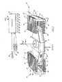
- Fig. 1 is a perspective view showing one embodiment of the electro-magnetic alignment assembly constructed according to the concepts of the present invention; and
- Fig. 2 is a perspective view similar to Fig. 1 but showing another embodiment of the invention.
- In the embodiment of the invention illustrated in Fig. 1, the electro-magnetic alignment apparatus comprises a first plurality of elements, including a first magnetic element 10, forming a first magnetic circuit indicated at 12, a second plurality of elements, including a
second magnet element 14, forming a second magnetic circuit indicated at 16, and a movable structural component indicated at 18. The movablestructural component 18 includes means for mounting an object, such as awafer 20 for example, thereon. - The first plurality of elements for forming the first
magnetic circuit 12 includes an ironupper plate 22, aniron bottom plate 24 and a side plate, which in the embodiment of Fig. 1 is the first magnet element 10. This magnet element 10 is a powerful permanent magnet and also serves to connect the upper and bottom plates. - The second plurality of elements for forming the second magnetic circuit. 16 includes an iron
upper plate 26, aniron bottom plate 28 and a side plate, which in the embodiment of Fig. 1 is thesecond magnet element 14. Thismagnet element 14, like the magnet element 10 is a powerful permanent magnet and serves to connect the upper and bottom plates. - One element of the first
magnetic circuit 12 is fixedly attached to the movablestructural component 18. In the embodiment of Fig. 1, this one element is aniron slug 30, which is movable between theupper plate 22 and thebottom plate 24. Likewise, one element of the secondmagnetic circuit 16 is fixedly attached to the movablestructural component 18 which, in the embodiment of Fig. 1, isiron slug 32, that is movable between theupper plate 26 and thebottom plate 28. - The first
magnetic circuit 12 has a first currentcarrying coil assembly 34, and a second current carryingcoil assembly 36 mounted at an angle with respect to the first coil assembly. In the embodiment of Fig. 1, these two current carrying coil assemblies are disposed orthogonally with respect to each other. - In a similar manner the second
magnetic circuit 16 has a third currentcarrying coil assembly 38, which is parallel to thefirst coil assembly 34, and a fourth currentcarrying coil assembly 40 mounted at an angle with respect to the third coil assembly. In this embodiment thethird coil assembly 38 is orthogonally disposed with respect to thefourth coil assembly 40. - In some embodiments two current carrying coil assemblies for each magnetic circuit are sufficient to establish the necessary motive forces, while in other embodiments additional current carrying coil assemblies are necessary. Fig. 1 shows, in the first
magnetic circuit 12, a fifth currentcarrying coil assembly 42, which is parallel to thefirst coil assembly 34 and a sixth currentcarrying coil assembly 44 which is parallel to thesecond coil assembly 36 and perpendicular to thefifth coil assembly 42. In the secondmagnetic circuit 16, a seventh currentcarrying coil assembly 46 is mounted parallel to thethird coil assembly 38, and an eighth currentcarrying coil assembly 48 is mounted parallel to thefourth coil assembly 40 and perpendicular to theseventh coil assembly 46. - The
first coil assembly 34 is provided with afirst lead 50 and asecond lead 52, while the second to the eighth coil assemblies are provided withleads controller 82, as will be discussed more fully hereinafter. - The movable
structural component 18 is mounted for movement with respect to the first and secondmagnetic circuits iron slug 30 and thebottom plate 24 and an air bearing mounted between theiron slug 32 and thebottom plate 28. Air is supplied to the air bearings by means of apiping system 84, provided for the purpose. - In some embodiments it may be desirable to fabricate the movable
structural component 18 with an aluminum honeycomb structure to provide structural strength at minimum weight, as indicated at 86. - Still referring to Fig. 1, any suitable sensor means may be used to sense the position of the object or wafer 20 mounted on the movable
structural component 18. Thus, a sensor 88 senses the position in the X direction,sensor 90 in the Y direction, andsensor 92 in the 8 direction. These sensors provide inputs to thecontroller 82. - In operation, the first
magnetic circuit 12 has a magnetic flux that follows the path from the magnet 10 through thebottom plate 24,slug 30,upper plate 22 and back to the magnet 10.Coils slug 30 and theupper plate 22, while coils 42 and 44, if employed, pass through the gap between theslug 30 and thebottom plate 24. - In a similar manner the second
magnetic circuit 16 has a magnetic flux that follows the path from themagnet 14 through theupper plate 26,slug 32, andbottom plate 28 back to themagnet 14.Coils slug 32 andupper plate 26, whilecoils slug 32 and thebottom plate 24. - The aforesaid magnetic flux bridges the gaps, and by modifying the flux in these areas with electric currents passing through the coils, a variety of forces may be produced on the movable
structural component 18. When the coils wound parallel to theX axis structural component 18 is forced along the Y axis. If the current in these coils is reversed, then the movable structural component and hence thewafer 20 will move along the Y axis in the opposite direction. Since there are two elements being forced,slug 30 andslug 32, which are separated by a moment arm, differential forcing of these elements in the Y direction causes a torque about the Z axis. That is, ifcoil coil wafer 20 will rotate. Excitation of the coils parallel to the Y axis,coils wafer 20 will move along the X axis in the opposite direction. - The above indicated force or movement is explained by Newton's third law, i.e., "Every force has an equal and opposite force" (or reaction). Current flowing through the wire exerts a lateral force on the wire when the wire is in a magnetic field. A "reaction force" is produced in the pole pieces which carry the magnetic field. In the present instance, since the fixed
elements slug structural component 18 with thewafer 20. - The
controller 82 may be of any suitable type. For example, it may have aninput 94 through which either manually or by microprocessor a command is given directing the movablestructural component 18 and hence thewafer 20 to move to a specific position. Thesensors - Referring next to the embodiment of Fig. 2, identical elements are referred to with the same reference numerals plus a prime mark.
- The structural differences between the embodiments of Figs. 1 and 2 resides in the location of the magnets in the magnetic circuits. Thus, in the first magnetic circuit the magnet 10 of Fig. 1 has been replaced by an
iron side plate 96 in Fig. 2. This fixed element serves to connect the upper plate 22' with the bottom plate 24' and it forms part of the magnetic flux path in the first magnetic circuit. In the embodiment of Fig. 2 themagnet 98, per se, is the one element of the first magnetic circuit 12' fixedly attached to the movable structural component 18'. As a result themagnet 98 is movable between the upper plate 22' and the bottom plate 24'. - .In the second magnetic circuit the
iron side plate 100 in the embodiment of Fig. 2 replaces themagnet 14 of Fig. 1, and themagnet 102 of Fig. 2 replaces theiron slug 32 of Fig. 1. - In all other respects the apparatus of Fig. 2 is constructed identical to that of Fig. 1. Both embodiments are controlled and operated in the same manner.
- It will thus be seen that the present invention does indeed provide an improved electro-magnetic alignment apparatus, which has higher precision with lower vibration and great simplicity, as compared to prior art such apparatus. There is substantially no backlash and very low friction because controlled motion in three degrees of freedom defined by planar motion is achieved with a single moving part. The lowest resonant frequency of the apparatus can be made very high. A very high band width servo can be used, which gives good control and high accuracy.
- Although certain particular embodiments of the invention are herein disclosed for purposes of explanation, further modifications thereof, after study of this specification, will be apparent to those skilled in the art to which the invention pertains. Reference should accordingly be had to the appended claims in determining the scope of the invention.
Claims (12)
characterized in that
Applications Claiming Priority (2)
| Application Number | Priority Date | Filing Date | Title |
|---|---|---|---|
| US502995 | 1983-06-10 | ||
| US06/502,995US4507597A (en) | 1983-06-10 | 1983-06-10 | Electro-magnetic alignment assemblies |
Publications (2)
| Publication Number | Publication Date |
|---|---|
| EP0130357A1 EP0130357A1 (en) | 1985-01-09 |
| EP0130357B1true EP0130357B1 (en) | 1988-03-30 |
Family
ID=24000327
Family Applications (1)
| Application Number | Title | Priority Date | Filing Date |
|---|---|---|---|
| EP84106001AExpiredEP0130357B1 (en) | 1983-06-10 | 1984-05-25 | Electro-magnetic alignment assemblies |
Country Status (5)
| Country | Link |
|---|---|
| US (1) | US4507597A (en) |
| EP (1) | EP0130357B1 (en) |
| JP (1) | JPS607724A (en) |
| CA (1) | CA1217223A (en) |
| DE (1) | DE3470234D1 (en) |
Families Citing this family (48)
| Publication number | Priority date | Publication date | Assignee | Title |
|---|---|---|---|---|
| DD222747A1 (en)* | 1983-11-30 | 1985-05-22 | Zeiss Jena Veb Carl | X-Y FLAECHEN DRIVE WITH LIMITED PHI TURN AND Z SHIFT |
| JPS60223119A (en)* | 1984-04-20 | 1985-11-07 | Hitachi Ltd | Noncontacting driving type precise moving base |
| NL8500930A (en)* | 1985-03-29 | 1986-10-16 | Philips Nv | MOVING DEVICE WITH PRESELVED CONTACTLESS BEARINGS. |
| US4654571A (en)* | 1985-09-16 | 1987-03-31 | Hinds Walter E | Single plane orthogonally movable drive system |
| US4808892A (en)* | 1985-12-13 | 1989-02-28 | Kulick And Soffa Ind. Inc. | Bi-directional drive motor system |
| JPS62199817A (en)* | 1986-02-27 | 1987-09-03 | Nippon Ester Co Ltd | Polyester conjugated yarn and production thereof |
| NL8601095A (en)* | 1986-04-29 | 1987-11-16 | Philips Nv | POSITIONING DEVICE. |
| US4789815A (en)* | 1986-07-23 | 1988-12-06 | Ohi Seisakusho Co., Ltd. | Linear motor |
| JPH01217914A (en)* | 1988-02-26 | 1989-08-31 | Canon Inc | Aligner |
| US4952858A (en)* | 1988-05-18 | 1990-08-28 | Galburt Daniel N | Microlithographic apparatus |
| NL8902472A (en)* | 1989-10-05 | 1991-05-01 | Philips Nv | POSITIONING DEVICE. |
| US5153494A (en)* | 1990-04-06 | 1992-10-06 | International Business Machines Corp. | Ultrafast electro-dynamic x, y and theta positioning stage |
| JPH05235077A (en)* | 1991-04-26 | 1993-09-10 | Texas Instr Inc <Ti> | Polar coordinate motion bonding head for bonding semiconductor device |
| US5239361A (en)* | 1991-10-25 | 1993-08-24 | Nicolet Instrument Corporation | Dynamic mirror alignment device for the interferometer of an infrared spectrometer |
| JPH06183561A (en)* | 1992-12-18 | 1994-07-05 | Canon Inc | Moving stage device |
| JPH07142336A (en)* | 1993-06-30 | 1995-06-02 | Canon Inc | Exposure equipment |
| US5528118A (en)* | 1994-04-01 | 1996-06-18 | Nikon Precision, Inc. | Guideless stage with isolated reaction stage |
| US6989647B1 (en)* | 1994-04-01 | 2006-01-24 | Nikon Corporation | Positioning device having dynamically isolated frame, and lithographic device provided with such a positioning device |
| US5874820A (en)* | 1995-04-04 | 1999-02-23 | Nikon Corporation | Window frame-guided stage mechanism |
| US7365513B1 (en) | 1994-04-01 | 2008-04-29 | Nikon Corporation | Positioning device having dynamically isolated frame, and lithographic device provided with such a positioning device |
| US6246204B1 (en) | 1994-06-27 | 2001-06-12 | Nikon Corporation | Electromagnetic alignment and scanning apparatus |
| US5623853A (en)* | 1994-10-19 | 1997-04-29 | Nikon Precision Inc. | Precision motion stage with single guide beam and follower stage |
| US6008500A (en)* | 1995-04-04 | 1999-12-28 | Nikon Corporation | Exposure apparatus having dynamically isolated reaction frame |
| TW318255B (en) | 1995-05-30 | 1997-10-21 | Philips Electronics Nv | |
| US5760564A (en)* | 1995-06-27 | 1998-06-02 | Nikon Precision Inc. | Dual guide beam stage mechanism with yaw control |
| US5699621A (en)* | 1996-02-21 | 1997-12-23 | Massachusetts Institute Of Technology | Positioner with long travel in two dimensions |
| DE19631106A1 (en)* | 1996-08-01 | 1998-02-05 | Heinz Peter Brandstetter | Stator plate or stator element |
| US6089525A (en)* | 1997-10-07 | 2000-07-18 | Ultratech Stepper, Inc. | Six axis active vibration isolation and payload reaction force compensation system |
| ID27189A (en)* | 1998-04-15 | 2001-03-08 | Pfaff Industriemaschinen Vertr | SEWING OR KNITTING MACHINE |
| US6144118A (en)* | 1998-09-18 | 2000-11-07 | General Scanning, Inc. | High-speed precision positioning apparatus |
| TW466542B (en) | 1999-02-26 | 2001-12-01 | Nippon Kogaku Kk | A stage device and a method of manufacturing same, a position controlling method, an exposure device and a method of manufacturing same, and a device and a method of manufacturing same |
| US6367287B1 (en)* | 1999-04-13 | 2002-04-09 | Owens-Brockway Glass Container Inc. | Two-axis motion of take-out tongs in an individual section glassware forming machine |
| US6355994B1 (en)* | 1999-11-05 | 2002-03-12 | Multibeam Systems, Inc. | Precision stage |
| US6307619B1 (en)* | 2000-03-23 | 2001-10-23 | Silicon Valley Group, Inc. | Scanning framing blade apparatus |
| US6405659B1 (en) | 2000-05-01 | 2002-06-18 | Nikon Corporation | Monolithic stage |
| US6737809B2 (en)* | 2000-07-31 | 2004-05-18 | Luxim Corporation | Plasma lamp with dielectric waveguide |
| US6922021B2 (en)* | 2000-07-31 | 2005-07-26 | Luxim Corporation | Microwave energized plasma lamp with solid dielectric waveguide |
| US7429818B2 (en)* | 2000-07-31 | 2008-09-30 | Luxim Corporation | Plasma lamp with bulb and lamp chamber |
| US6803738B2 (en) | 2000-10-13 | 2004-10-12 | Clarity, Llc | Magnetic actuation and positioning |
| US6879082B2 (en)* | 2002-03-25 | 2005-04-12 | Clarity Technologies, Inc. | Electromagnetic positioning |
| US7259832B2 (en)* | 2003-09-26 | 2007-08-21 | Asml Netherlands B.V. | Lithographic apparatus and device manufacturing method |
| JP4323409B2 (en)* | 2003-10-21 | 2009-09-02 | エーエスエムエル ネザーランズ ビー.ブイ. | Positioning system and positioning method |
| US7884326B2 (en)* | 2007-01-22 | 2011-02-08 | Fei Company | Manipulator for rotating and translating a sample holder |
| EP1947675B1 (en)* | 2007-01-22 | 2009-03-25 | FEI Company | Manipulator for rotating and translating a sample holder |
| TWI347469B (en)* | 2007-04-27 | 2011-08-21 | Hon Hai Prec Ind Co Ltd | Fixation device and method for controlling thereof |
| EP2051280A1 (en)* | 2007-10-18 | 2009-04-22 | The Regents of the University of California | Motorized manipulator for positioning a TEM specimen |
| US20130052919A1 (en)* | 2011-08-25 | 2013-02-28 | Space Administrationo | Graphite composite panel polishing fixture and assembly |
| US9507276B2 (en)* | 2012-10-09 | 2016-11-29 | Koninklijke Philips N.V. | Positioning device, control device and control method |
Family Cites Families (11)
| Publication number | Priority date | Publication date | Assignee | Title |
|---|---|---|---|---|
| US27289A (en)* | 1860-02-28 | Island | ||
| US27436A (en)* | 1860-03-13 | Kaitge | ||
| AU411601B2 (en) | 1966-05-31 | 1971-03-12 | Alden Sawyer | Magnetic positioning device |
| DE1522287A1 (en)* | 1966-07-01 | 1969-08-07 | Telefunken Patent | Device for fine adjustment of photo masks |
| US3457482A (en) | 1967-10-30 | 1969-07-22 | Bruce A Sawyer | Magnetic positioning device |
| US3789285A (en)* | 1972-03-27 | 1974-01-29 | Handotai Kenkyu Shinkokai | Position control system using magnetic force |
| US3889164A (en)* | 1973-01-24 | 1975-06-10 | Handotai Kenkyu Shinkokai | Position control system using magnetic forces for correcting the inclination of a controlled member including a torsional mounting |
| JPS553679B2 (en)* | 1973-08-27 | 1980-01-26 | ||
| US4019109A (en)* | 1974-05-13 | 1977-04-19 | Hughes Aircraft Company | Alignment system and method with micromovement stage |
| JPS51123565A (en)* | 1975-04-21 | 1976-10-28 | Nippon Telegr & Teleph Corp <Ntt> | Three-dimention-position differential adjustment of processing article |
| DE3132919A1 (en)* | 1980-12-09 | 1982-09-02 | VEB Zentrum für Forschung und Technologie Mikroelektronik, DDR 8080 Dresden | Servo-drive |
- 1983
- 1983-06-10USUS06/502,995patent/US4507597A/ennot_activeExpired - Lifetime
- 1984
- 1984-05-04CACA000453576Apatent/CA1217223A/ennot_activeExpired
- 1984-05-25DEDE8484106001Tpatent/DE3470234D1/ennot_activeExpired
- 1984-05-25EPEP84106001Apatent/EP0130357B1/ennot_activeExpired
- 1984-06-11JPJP59118398Apatent/JPS607724A/enactiveGranted
Also Published As
| Publication number | Publication date |
|---|---|
| US4507597A (en) | 1985-03-26 |
| CA1217223A (en) | 1987-01-27 |
| JPS607724A (en) | 1985-01-16 |
| JPH0586845B2 (en) | 1993-12-14 |
| DE3470234D1 (en) | 1988-05-05 |
| EP0130357A1 (en) | 1985-01-09 |
Similar Documents
| Publication | Publication Date | Title |
|---|---|---|
| EP0130357B1 (en) | Electro-magnetic alignment assemblies | |
| EP0128433B1 (en) | Electro-magnetic alignment apparatus | |
| US4485339A (en) | Electro-magnetic alignment device | |
| EP0905869B1 (en) | Linear motor for exposure apparatus, and a device manufacturing method using the same | |
| US5196745A (en) | Magnetic positioning device | |
| JP3815750B2 (en) | Stage apparatus, and exposure apparatus and device manufacturing method using the stage apparatus | |
| JP3945148B2 (en) | XY table and XYZ table | |
| JP4639517B2 (en) | Stage apparatus, lithography system, positioning method, and stage apparatus driving method | |
| US6960846B2 (en) | Linear pulse motor, stage apparatus, and exposure apparatus | |
| US6479991B1 (en) | Stage mechanism, exposure apparatus and device manufacturing method in which a coil unit of a driving mechanism is moved substantially in synchronism with a stage | |
| US5962937A (en) | X-Y table for moving loads in a highly exact and dynamic manner | |
| EP0421529B1 (en) | Linear motor and positioning device comprising at least one linear motor | |
| JP2004172557A (en) | Stage device and control method thereof | |
| JP2716884B2 (en) | Flat motor device | |
| JP2908249B2 (en) | Flat motor device | |
| JP4137091B2 (en) | Stage apparatus, linear motor, and exposure apparatus and device manufacturing method using the stage apparatus | |
| JP3409864B2 (en) | Motor device having linear motor structure | |
| KR20230153257A (en) | Stage apparatus, transfer apparatus and article manufacturing method | |
| JP2001025228A (en) | Linear motor | |
| JP2005203652A (en) | Positioning device |
Legal Events
| Date | Code | Title | Description |
|---|---|---|---|
| PUAI | Public reference made under article 153(3) epc to a published international application that has entered the european phase | Free format text:ORIGINAL CODE: 0009012 | |
| AK | Designated contracting states | Designated state(s):CH DE FR GB IT LI NL | |
| 17P | Request for examination filed | Effective date:19850705 | |
| 17Q | First examination report despatched | Effective date:19860923 | |
| GRAA | (expected) grant | Free format text:ORIGINAL CODE: 0009210 | |
| AK | Designated contracting states | Kind code of ref document:B1 Designated state(s):CH DE FR GB IT LI NL | |
| ITF | It: translation for a ep patent filed | ||
| REF | Corresponds to: | Ref document number:3470234 Country of ref document:DE Date of ref document:19880505 | |
| ET | Fr: translation filed | ||
| PLBE | No opposition filed within time limit | Free format text:ORIGINAL CODE: 0009261 | |
| STAA | Information on the status of an ep patent application or granted ep patent | Free format text:STATUS: NO OPPOSITION FILED WITHIN TIME LIMIT | |
| 26N | No opposition filed | ||
| REG | Reference to a national code | Ref country code:CH Ref legal event code:PUE Owner name:SVG LITHOGRAPHY SYSTEMS, INC. | |
| NLS | Nl: assignments of ep-patents | Owner name:SVG LITHOGRAPHY SYSTEMS, INC. TE WILTON, CONNECTIC | |
| REG | Reference to a national code | Ref country code:FR Ref legal event code:TP | |
| REG | Reference to a national code | Ref country code:GB Ref legal event code:732 | |
| ITPR | It: changes in ownership of a european patent | Owner name:CESSIONE;SVG LITHOGRAPHY SYSTEMS INC. | |
| ITTA | It: last paid annual fee | ||
| PGFP | Annual fee paid to national office [announced via postgrant information from national office to epo] | Ref country code:CH Payment date:20010430 Year of fee payment:18 | |
| REG | Reference to a national code | Ref country code:GB Ref legal event code:IF02 | |
| PG25 | Lapsed in a contracting state [announced via postgrant information from national office to epo] | Ref country code:LI Free format text:LAPSE BECAUSE OF NON-PAYMENT OF DUE FEES Effective date:20020531 Ref country code:CH Free format text:LAPSE BECAUSE OF NON-PAYMENT OF DUE FEES Effective date:20020531 | |
| REG | Reference to a national code | Ref country code:CH Ref legal event code:PL | |
| PGFP | Annual fee paid to national office [announced via postgrant information from national office to epo] | Ref country code:GB Payment date:20030401 Year of fee payment:20 | |
| PGFP | Annual fee paid to national office [announced via postgrant information from national office to epo] | Ref country code:NL Payment date:20030403 Year of fee payment:20 | |
| PGFP | Annual fee paid to national office [announced via postgrant information from national office to epo] | Ref country code:FR Payment date:20030505 Year of fee payment:20 | |
| PGFP | Annual fee paid to national office [announced via postgrant information from national office to epo] | Ref country code:DE Payment date:20030530 Year of fee payment:20 | |
| PG25 | Lapsed in a contracting state [announced via postgrant information from national office to epo] | Ref country code:GB Free format text:LAPSE BECAUSE OF EXPIRATION OF PROTECTION Effective date:20040524 | |
| PG25 | Lapsed in a contracting state [announced via postgrant information from national office to epo] | Ref country code:NL Free format text:LAPSE BECAUSE OF EXPIRATION OF PROTECTION Effective date:20040525 | |
| REG | Reference to a national code | Ref country code:GB Ref legal event code:PE20 | |
| NLV7 | Nl: ceased due to reaching the maximum lifetime of a patent | Effective date:20040525 |