EP0128407A1 - Seat - Google Patents
SeatDownload PDFInfo
- Publication number
- EP0128407A1 EP0128407A1EP84105798AEP84105798AEP0128407A1EP 0128407 A1EP0128407 A1EP 0128407A1EP 84105798 AEP84105798 AEP 84105798AEP 84105798 AEP84105798 AEP 84105798AEP 0128407 A1EP0128407 A1EP 0128407A1
- Authority
- EP
- European Patent Office
- Prior art keywords
- seat according
- wire
- seat
- frame
- transverse
- Prior art date
- Legal status (The legal status is an assumption and is not a legal conclusion. Google has not performed a legal analysis and makes no representation as to the accuracy of the status listed.)
- Granted
Links
- 230000005489elastic deformationEffects0.000claimsdescription7
- XEEYBQQBJWHFJM-UHFFFAOYSA-NIronChemical compound[Fe]XEEYBQQBJWHFJM-UHFFFAOYSA-N0.000claimsdescription4
- 125000006850spacer groupChemical group0.000claimsdescription3
- 229910052742ironInorganic materials0.000claimsdescription2
- 239000004033plasticSubstances0.000claimsdescription2
- 229910000831SteelInorganic materials0.000claims1
- 239000010959steelSubstances0.000claims1
- 239000000725suspensionSubstances0.000description11
- 229910000639Spring steelInorganic materials0.000description2
- 230000000694effectsEffects0.000description2
- 239000004744fabricSubstances0.000description2
- 239000000463materialSubstances0.000description2
- 239000002984plastic foamSubstances0.000description2
- 239000004743PolypropyleneSubstances0.000description1
- 238000005553drillingMethods0.000description1
- 230000008030eliminationEffects0.000description1
- 238000003379elimination reactionMethods0.000description1
- ZINJLDJMHCUBIP-UHFFFAOYSA-Nethametsulfuron-methylChemical compoundCCOC1=NC(NC)=NC(NC(=O)NS(=O)(=O)C=2C(=CC=CC=2)C(=O)OC)=N1ZINJLDJMHCUBIP-UHFFFAOYSA-N0.000description1
- 238000004519manufacturing processMethods0.000description1
- 239000002184metalSubstances0.000description1
- 229910052751metalInorganic materials0.000description1
- -1polypropylenePolymers0.000description1
- 229920001155polypropylenePolymers0.000description1
- 239000007787solidSubstances0.000description1
- 230000003313weakening effectEffects0.000description1
- 230000004584weight gainEffects0.000description1
- 235000019786weight gainNutrition0.000description1
Images
Classifications
- A—HUMAN NECESSITIES
- A47—FURNITURE; DOMESTIC ARTICLES OR APPLIANCES; COFFEE MILLS; SPICE MILLS; SUCTION CLEANERS IN GENERAL
- A47C—CHAIRS; SOFAS; BEDS
- A47C7/00—Parts, details, or accessories of chairs or stools
- A47C7/02—Seat parts
- A47C7/28—Seat parts with tensioned springs, e.g. of flat type
- A47C7/32—Seat parts with tensioned springs, e.g. of flat type with tensioned cords, e.g. of elastic type, in a flat plane
- B—PERFORMING OPERATIONS; TRANSPORTING
- B05—SPRAYING OR ATOMISING IN GENERAL; APPLYING FLUENT MATERIALS TO SURFACES, IN GENERAL
- B05D—PROCESSES FOR APPLYING FLUENT MATERIALS TO SURFACES, IN GENERAL
- B05D1/00—Processes for applying liquids or other fluent materials
- B05D1/28—Processes for applying liquids or other fluent materials performed by transfer from the surfaces of elements carrying the liquid or other fluent material, e.g. brushes, pads, rollers
- A—HUMAN NECESSITIES
- A47—FURNITURE; DOMESTIC ARTICLES OR APPLIANCES; COFFEE MILLS; SPICE MILLS; SUCTION CLEANERS IN GENERAL
- A47C—CHAIRS; SOFAS; BEDS
- A47C7/00—Parts, details, or accessories of chairs or stools
- A47C7/36—Supports for the head or the back
- A47C7/40—Supports for the head or the back for the back
Definitions
- the present inventionrelates to all types of furniture seats, vehicles, etc. comprising suspension means making it possible to provide the user with the desired support and comfort.
- the object of this inventiontherefore consists in providing a seat which does not have the drawbacks of known suspension seats of the aforementioned type.
- This objectis achieved by the seat, object of the invention, which comprises a lower frame and an upper frame on which are fixed bearing surfaces respectively forming the bottom and the backrest, and which is characterized in that at least one bearing surfaces is constituted by an elastic sheet formed of wires arranged transversely, each wire having at least one permanent elastic deformation.
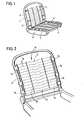
- Certain known seatsintended more particularly for equipping automobiles, are of the type illustrated in FIG. 1 and comprise two respectively upper 1 and lower 2 frames, generally metallic and produced by stamped parts, profiles or tubular elements.
- the bearing or support surfacesnamely the backrest and the bottom, can be constituted by metallic trellis 3,4, fixed to lateral strips 5,6.
- Each rigid trellis-side rod assemblyis fixed laterally to the upper and lower frame respectively by means of springs 7,8, these being on the one hand hooked to the lateral rods 5,6 and on the other fixed in holes made in the respective frames 1,2.
- the frames and the trellisesare covered for example with plastic foam and a fabric or other external material enveloping it in order to constitute the finished seat.
- the rigid metallic trellisrespectively forming the bottom and the back of the seat and suspended from the respective frames, are replaced by sheets which themselves have the elasticity. city required and formed of transverse wires fixed to said frames.
- FIG 2is illustrated an embodiment of an elastic ply 10 fixed to the upper frame 11 of a seat according to the invention and constituting the back thereof.
- This sheet 10is formed of a plurality of metal wires 12 arranged transversely practically parallel to one another.
- Each wirehas a permanent elastic deformation 13, here in the middle portion of the wire.
- Thiscan consist of an iron wire, or preferably a normal or hardened spring steel wire (for example according to DIN 2076 standard).
- each wireis preferably located in a plane, and more particularly that of the sheet; its geometry can be that illustrated in FIG. 2, that is to say with a linear portion offset parallel to the rest of the wire and connected to it by two oblique portions (hereinafter referred to as "bowl" shape ").
- Each deformationcan of course have other shapes, for example a sawtooth shape with a preferably relatively small pitch or a preferably relatively flattened spring shape (not shown).
- the wirecan have one or more of these deformations along its length.
- the transverse wires 12are preferably fixed by their ends to the lateral branches of a support element 14 here in the form of a U.
- the support element 14 carrying the elastic sheet or spring 10is fixed to the frame by means of clips 15 pinched on the tube 11 constituting this frame.
- Figures 6 and 7illustrate two variants 15,15 'of these clips, which can be made of spring steel, plastic, etc.
- elements 16are arranged in the plane of the ply perpendicular to said wires, the latter passing through openings salsa practiced in these elements at regular intervals.
- These spacers 16may for example be made of polypropylene cords.
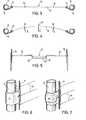
- the section of FIG. 3makes it possible to better illustrate on the one hand the fact that the deformation 13 presented by the middle part of the wire 12 is indeed in the plane of the sheet, and on the other hand the fixing of the support 14 of the sheet to the tubular frame 11 by means of the clips 15.
- the section of FIG. 4shows the deformation of the wire 12 under the effect of a push according to the arrows V due for example to the support against the backrest of the back of the seat user.
- Figure 5shows in more detail and in plan the elastic deformation 13 of the wire 12.
- solid lineis illustrated the position of the wire 12 before the assembly of the web on the square
- the ratio between the dimensions of the oblique portions 13 ' and of the offset linear portion 13 "of the cup-shaped deformationcan be modified according to the desired spring effect.
- broken linesis illustrated the shape of the deformation 13 in the rest position of the wire 12, the elastic sheet being fixed to the frame and the support uprights 14 being slightly more spaced from one another, while the dashed lines illustrate the shape of said deformation 13 when the wire 12 is stressed by a thrust substantially perpendicular to the plane of the spring ply .
- the seat according to the invention as described above with reference to the drawingsis still covered, for example, with a plastic foam, a fabric or another material enveloping it. to constitute the finished seat.
- the seat according to the inventionhas the particular advantage of being more comfortable, the spring ply having better elasticity characteristics than a rigid trellis suspended laterally, because it s spans out at least part of the bearing surface.
- the possibility of providing different forms of deformation and of arranging them differently on the surface of the elastic plyallows the seat according to the invention to be given different elastic characteristics which are distributed differently depending, for example, on the external lining envisaged. the seat (shape and elasticity of the padding in particular), the nature of the vehicle intended to be fitted with the seat (utility, luxury, sports car, etc.) and other factors such as the weight of the user, vehicle suspension characteristics, etc.
- the fixing of the elastic sheet to the frame by means of simple clipsfacilitates manufacture, since it avoids the drilling of orifices in the frame and allows the use of light tubular frames, and on the other part allows delivery of the seat in parts and makes its final assembly easy.
Landscapes
- Seats For Vehicles (AREA)
- Chair Legs, Seat Parts, And Backrests (AREA)
- Acyclic And Carbocyclic Compounds In Medicinal Compositions (AREA)
- Connection Of Plates (AREA)
Abstract
Description
Translated fromFrenchLa présente invention se rapporte à tous types de sièges d'ameublement, de véhicules, etc. comportant des moyens de suspension permettant d'apporter à l'utilisateur le support et le confort désirés.The present invention relates to all types of furniture seats, vehicles, etc. comprising suspension means making it possible to provide the user with the desired support and comfort.
On connaît déjà des sièges, notamment pour véhicules, qui comportent un fond et un dossier fixés chacun respectivement à un cadre inférieur et à un cadre supérieur au moyen d'éléments élastiques, par exemple des ressorts hélicoïdaux, le tout étant recouvert selon la destination prévue du siège d'un rembourrage et/ou d'une garniture extérieure. Généralement, le fond et le dossier suspendus aux cadres sont formés d'un treillis métallique rigide. Toutefois, le confort offert par ce type de siège n'est pas toujours satisfaisant, notamment dans le cas d'un véhicule automobile dans lequel l'usager est soumis à des mouvements répétés et brusques. De plus, les ressorts de suspension du fond et du dossier étant très sollicités, ils perdent relativement rapidement leurs caractéristiques élastiques et la suspension devient insuffisante. Enfin, dans ce type de siège, il est nécessaire de prévoir des cadres suffisamment solides et épais pour supporter l'affaiblissement dû aux orifices pratiqués en vue de l'accrochage des ressorts de suspension.There are already known seats, in particular for vehicles, which have a bottom and a back, each fixed respectively to a lower frame and to an upper frame by means of elastic elements, for example helical springs, the whole being covered according to the intended destination. of the seat with padding and / or an exterior trim. Generally, the bottom and the back hanging from the frames are formed of a rigid wire mesh. However, the comfort offered by this type of seat is not always satisfactory, in particular in the case of a motor vehicle in which the user is subjected to repeated and sudden movements. In addition, the suspension springs of the bottom and the backrest being very stressed, they lose their elastic characteristics relatively quickly and the suspension becomes insufficient. Finally, in this type of seat, it is necessary to provide frames which are sufficiently solid and thick to withstand the weakening due to the orifices made for hooking the suspension springs.
Le but de cette invention consiste donc à fournir un siège qui ne présente pas les inconvénients des sièges avec suspension connus du type précité. Ce but est atteint par le siège, objet de l'invention, qui comporte un cadre inférieur et un cadre supérieur sur lesquels sont fixées des surfaces portantes formant respectivement le fond et le dossier, et qui est caractérisé par le fait qu'au moins une des surfaces portantes est constituée par une nappe élastique formée de fils disposés transversalement, chaque fil présentant au moins une déformation élastique permanente.The object of this invention therefore consists in providing a seat which does not have the drawbacks of known suspension seats of the aforementioned type. This object is achieved by the seat, object of the invention, which comprises a lower frame and an upper frame on which are fixed bearing surfaces respectively forming the bottom and the backrest, and which is characterized in that at least one bearing surfaces is constituted by an elastic sheet formed of wires arranged transversely, each wire having at least one permanent elastic deformation.
Le dessin annexé illustre schématiquement et à titre d'exemple l'invention.
- La figure 1 est une vue en perspective d'un siège avec suspension de type connu.
- La figure 2 est une vue partielle en perspective d'une forme d'exécution du siège avec suspension selon l'invention.
- La figure 3 est une vue en coupe de la nappe formant le dossier du siège illustré à la figure 2.
- Les figures 4 et 5 sont des vues respectivement en coupe et en plan d'un détail de la nappe illustrant la déformation élastique d'un des fils constituant cette nappe.
- Les figures 6 et 7 sont des vues en perspective de deux variantes des éléments de fixation au cadre d'une nappe de fils.
- Figure 1 is a perspective view of a seat with suspension of known type.
- Figure 2 is a partial perspective view of an embodiment of the seat with suspension according to the invention.
- FIG. 3 is a sectional view of the ply forming the seat back illustrated in FIG. 2.
- Figures 4 and 5 are views respectively in section and in plan of a detail of the ply illustrating the elastic deformation of one of the son constituting this ply.
- Figures 6 and 7 are perspective views of two variants of the fastening elements to the frame of a ply of son.
Certains sièges connus, destinés plus particulièrement à équiper des automobiles, sont du type illustré sur la figure 1 et comportent deux cadres respectivement supérieur 1 et inférieur 2 généralement métalliques et réalisés par des pièces embouties, des profilés ou des éléments tubulaires. Les surfaces portantes ou de support, à savoir le dossier et le fond, peuvent être constituées par des treillis métalliques 3,4, fixés à des baguettes latérales 5,6. Chaque ensemble rigide treillis-baguettes latérales est fixé latéralement au cadre respectivement supérieur et inférieur au moyen de ressorts 7,8, ceux-ci étant d'une part accrochés aux baguettes latérales 5,6 et d'autre part fixés dans des orifices pratiqués dans les cadres respectifs 1,2. Bien entendu, les cadres et les treillis sont recouverts par exemple avec de la mousse plastique et un tissu ou un autre matériau extérieur enveloppant celle-ci afin de constituer le siège fini.Certain known seats, intended more particularly for equipping automobiles, are of the type illustrated in FIG. 1 and comprise two respectively upper 1 and lower 2 frames, generally metallic and produced by stamped parts, profiles or tubular elements. The bearing or support surfaces, namely the backrest and the bottom, can be constituted by
Dans les sièges selon l'invention, les treillis métalliques rigides, formant respectivement le fond et le dossier du siège et suspendus aux cadres respectifs, sont remplacés par des nappes présentant elles-mêmes l'élasticité requise et formées de fils transversaux fixés auxdits cadres.In the seats according to the invention, the rigid metallic trellis, respectively forming the bottom and the back of the seat and suspended from the respective frames, are replaced by sheets which themselves have the elasticity. city required and formed of transverse wires fixed to said frames.
Sur la figure 2 est illustrée une réalisation d'une nappe élastique 10 fixée au cadre supérieur 11 d'un siège selon l'invention et constituant le dossier de celui-ci. Cette nappe 10 est formée d'une pluralité de fils métalliques 12 disposés transversalement pratiquement parallèlement les uns aux autres. Chaque fil présente une déformation élastique permanente 13, ici dans la portion médiane du fil. Celui-ci peut être constitué d'un fil de fer, ou de préférence d'un fil en acier ressort normal ou trempé (par exemple selon norme DIN 2076).In Figure 2 is illustrated an embodiment of an
La déformation que présente chaque fil est de préférence située dans un plan, et plus particulièrement celui de la nappe; sa géométrie peut être celle illustrée sur la figure 2, c'est-à-dire avec une portion linéaire décalée parallèlement par rapport au reste du fil et reliée à celui-ci par deux portions obliques (ci-après désignée comme forme "en cuvette"). Chaque déformation peut bien entendu présenter d'autres formes, par exemple une forme en dents de scie avec un pas de préférence relativement faible ou une forme de ressort de préférence relativement aplati (non illustrées). Le fil peut présenter sur sa longueur une seule ou plusieurs de ces déformations.The deformation presented by each wire is preferably located in a plane, and more particularly that of the sheet; its geometry can be that illustrated in FIG. 2, that is to say with a linear portion offset parallel to the rest of the wire and connected to it by two oblique portions (hereinafter referred to as "bowl" shape "). Each deformation can of course have other shapes, for example a sawtooth shape with a preferably relatively small pitch or a preferably relatively flattened spring shape (not shown). The wire can have one or more of these deformations along its length.
Les fils transversaux 12 sont de préférence fixés par leurs extrémités aux branches latérales d'un élément-support 14 ici en forme de U. L'élément-support 14 portant la nappe élastique ou ressort 10 est fixé au cadre au moyen de clips 15 pincés sur le tube 11 constituant ce cadre. Les figures 6 et 7 illustrent deux variantes 15,15' de ces clips, qui peuvent être réalisées en acier ressort, en matière plastique, etc.The
Pour maintenir l'écartement entre les fils 12 constituant la nappe élastique 10, des éléments 16 sont disposés dans le plan de la nappe perpendiculairement auxdits fils, ceux-ci passant dans des orifices transversaux pratiqués dans ces éléments à intervales réguliers. Ces éléments d'écartement 16 peuvent par exemple être constitués de cordes en polypropylène.To maintain the spacing between the
La coupe de la figure 3 permet de mieux illustrer d'une part le fait que la déformation 13 que présente la partie médiane du fil 12 est bien dans le plan de la nappe, et d'autre part la fixation du support 14 de la nappe au cadre tubulaire 11 au moyen du clips 15. Quant à la coupe de la figure 4, elle montre la déformation du fil 12 sous l'effet d'une poussée selon les flèches V due par exemple à l'appui contre le dossier du dos de l'utilisateur du siège.The section of FIG. 3 makes it possible to better illustrate on the one hand the fact that the
Enfin, la figure 5 montre plus en détail et en plan la déformation élastique 13 du fil 12. En trait plein est illustrée la position du fil 12 avant l'assemblage de la nappe sur le cadrée Le rapport entre les dimensions des portions obliques 13' et de la portion linéaire décalée 13" de la déformation en forme de cuvette peut être modifié selon l'effet ressort recherché. En trait interrompu est illustrée la forme de la déformation 13 dans la position de repos du fil 12, la nappe élastique étant fixée au cadre et les montants-supports 14 étant légèrement plus écartés l'un de l'autre, alors que les traits mixtes. illustrent la forme de ladite déformation 13 lorsque le fil 12 est sollicité par une poussée sensiblement perpendiculaire au plan de la nappe ressort.Finally, Figure 5 shows in more detail and in plan the
Comme dans le cas des sièges de type classique, le siège selon l'invention tel qu'il a été décrit ci-dessus en référence aux dessins est encore recouvert par exemple avec une mousse plastique, un tissu ou un autre matériau enveloppant celle-ci pour constituer le siège fini.As in the case of seats of the conventional type, the seat according to the invention as described above with reference to the drawings is still covered, for example, with a plastic foam, a fabric or another material enveloping it. to constitute the finished seat.
Par rapport aux sièges avec suspension connus, le siège selon l'invention présente notamment l'avantage d'être plus confortable, la nappe ressort présentant de meilleures caractéristiques d'élasticité qu'un treillis rigide suspendu latéralement, du fait qu'elle s'étend sur une partie au moins de la surface portante. En outre, la possibilité de prévoir différentes formes de déformations et de les disposer différemment sur la surface de la nappe élastique permet de conférer au siège selon l'invention des caractéristiques élastiques différentes et réparties différemment en fonction, par exemple, de la garniture extérieure envisagée du siège (forme et élasticité propre du rembourrage notamment), de la nature du véhicule destiné à être équipé du siège (automobile utilitaire, de luxe, de sport, etc.) et d'autres facteurs tels que le poids de l'utilisateur, caractéristiques de la suspension du véhicule, etc.Compared to known suspension seats, the seat according to the invention has the particular advantage of being more comfortable, the spring ply having better elasticity characteristics than a rigid trellis suspended laterally, because it s spans out at least part of the bearing surface. In addition, the possibility of providing different forms of deformation and of arranging them differently on the surface of the elastic ply allows the seat according to the invention to be given different elastic characteristics which are distributed differently depending, for example, on the external lining envisaged. the seat (shape and elasticity of the padding in particular), the nature of the vehicle intended to be fitted with the seat (utility, luxury, sports car, etc.) and other factors such as the weight of the user, vehicle suspension characteristics, etc.
De plus la fixation de la nappe élastique sur le cadre au moyen de simples clips d'une part facilite la fabrication, puisqu'elle évite le percement d'orifices dans le cadre et permet l'utilisation de cadres tubulaires légers, et d'autre part permet la livraison en pièces détachées du siège et rend son assemblage final aisé.In addition, the fixing of the elastic sheet to the frame by means of simple clips on the one hand facilitates manufacture, since it avoids the drilling of orifices in the frame and allows the use of light tubular frames, and on the other part allows delivery of the seat in parts and makes its final assembly easy.
Enfin, la suppression des ressorts hélicoïdaux habituellement utilisés pour suspendre le fond et le dossier des sièges connus, et qui sont généralement au nombre de huit, et leur remplacement par de simples clips (par exemple six) dans le siège selon l'invention, permet d'obtenir pour celui-ci . un gain de poids appréciable.Finally, the elimination of the coil springs usually used to suspend the bottom and the back of known seats, which are generally eight in number, and their replacement by simple clips (for example six) in the seat according to the invention, allows to get for this one. appreciable weight gain.
Claims (9)
Translated fromFrenchPriority Applications (1)
| Application Number | Priority Date | Filing Date | Title |
|---|---|---|---|
| AT84105798TATE28266T1 (en) | 1983-06-10 | 1984-05-21 | SEAT. |
Applications Claiming Priority (2)
| Application Number | Priority Date | Filing Date | Title |
|---|---|---|---|
| CH3189/83 | 1983-06-10 | ||
| CH3189/83ACH652290A5 (en) | 1983-06-10 | 1983-06-10 | SEAT. |
Publications (2)
| Publication Number | Publication Date |
|---|---|
| EP0128407A1true EP0128407A1 (en) | 1984-12-19 |
| EP0128407B1 EP0128407B1 (en) | 1987-07-15 |
Family
ID=4250559
Family Applications (1)
| Application Number | Title | Priority Date | Filing Date |
|---|---|---|---|
| EP84105798AExpiredEP0128407B1 (en) | 1983-06-10 | 1984-05-21 | Seat |
Country Status (9)
| Country | Link |
|---|---|
| EP (1) | EP0128407B1 (en) |
| JP (1) | JPS59228809A (en) |
| KR (1) | KR920007610B1 (en) |
| AT (1) | ATE28266T1 (en) |
| BR (1) | BR8402696A (en) |
| CH (1) | CH652290A5 (en) |
| DE (2) | DE128407T1 (en) |
| ES (1) | ES288723Y (en) |
| ZA (1) | ZA844158B (en) |
Cited By (12)
| Publication number | Priority date | Publication date | Assignee | Title |
|---|---|---|---|---|
| GB2308809A (en)* | 1996-01-05 | 1997-07-09 | Youngflex Sa | Wire framework support for incorporation in a seat frame |
| EP0867333A3 (en)* | 1997-03-24 | 1999-06-30 | Hoover Universal,Inc. | Wire attachment to a seat frame |
| US6152531A (en)* | 1996-08-23 | 2000-11-28 | Youngflex Ag | Seat suspension arrangement and adjustment mechanism therefore |
| US6994399B2 (en) | 2001-11-28 | 2006-02-07 | L&P Swiss Holding Company | Seat back suspension arrangement |
| EP1683442A1 (en)* | 2005-01-19 | 2006-07-26 | L&P Swiss Holding Company | Support structure for a seat with a table function and corresponding seat suspension arrangement |
| CN102079259A (en)* | 2011-01-21 | 2011-06-01 | 金文哲 | Steel wire hanging device for vehicle seat and manufacturing method thereof |
| DE102012014029A1 (en) | 2012-07-14 | 2014-01-16 | Scherdel Marienberg Gmbh | Pad carrier for e.g. backrest of vehicle seat, has grid-shaped structure made of spring steel wire, where longitudinal and transverse strands of structure and shaping wire are firmly connected with each other without welding rod materials |
| DE102012014210A1 (en)* | 2012-07-18 | 2014-02-06 | Johnson Controls Gmbh | Seat component for vehicle seat e.g. motor car seat, has non-metallic receiving element that is secured at metallic support structure, and that is connected to end of wire and recesses |
| WO2016188590A1 (en)* | 2015-05-22 | 2016-12-01 | Schukra Gerätebau Gmbh | Coupling unit for a support structure |
| US9604560B1 (en) | 2015-11-13 | 2017-03-28 | Kongsberg Automotive, Inc. | Assembly for adjusting a lumbar region of a seat |
| US20190184872A1 (en)* | 2016-08-04 | 2019-06-20 | Ts Tech Co., Ltd. | Seat |
| US10427569B2 (en) | 2015-01-26 | 2019-10-01 | Kongsberg Automotive, Inc. | Adjustment mechanism for a seat |
Families Citing this family (6)
| Publication number | Priority date | Publication date | Assignee | Title |
|---|---|---|---|---|
| US6880886B2 (en)* | 2002-09-12 | 2005-04-19 | Steelcase Development Corporation | Combined tension and back stop function for seating unit |
| US7090301B2 (en) | 2002-10-29 | 2006-08-15 | L&P Property Management Company | Apparatus and method for lumbar support structure |
| WO2006029204A1 (en) | 2004-09-07 | 2006-03-16 | L & P Property Management Company | Mechanism for thin seat lumbar |
| JP5388271B2 (en)* | 2008-10-20 | 2014-01-15 | 日本発條株式会社 | Back seat frame structure of vehicle seat and vehicle seat having the structure |
| EP2177396B1 (en) | 2008-10-20 | 2013-06-05 | NHK SPRING Co., Ltd. | Seat back frame structure of seat for vehicle and seat for vehicle with seat back frame structure field of the invention |
| JP5388273B2 (en)* | 2008-11-19 | 2014-01-15 | 日本発條株式会社 | Back seat frame structure of vehicle seat and vehicle seat having the structure |
Citations (3)
| Publication number | Priority date | Publication date | Assignee | Title |
|---|---|---|---|---|
| US3137489A (en)* | 1963-05-09 | 1964-06-16 | Van Dresser Specialty Corp | Seat spring structure |
| FR2381495A1 (en)* | 1977-02-28 | 1978-09-22 | Youngflex Sa | CUSHION-FORMING ELEMENT SUPPORT DEVICE |
| FR2495454A1 (en)* | 1980-12-08 | 1982-06-11 | Lear Siegler Inc | SUPPORT FOR PADDING |
Family Cites Families (1)
| Publication number | Priority date | Publication date | Assignee | Title |
|---|---|---|---|---|
| JPS5838513A (en)* | 1981-08-31 | 1983-03-07 | 株式会社タチエス | Sheet support for vehicle |
- 1983
- 1983-06-10CHCH3189/83Apatent/CH652290A5/ennot_activeIP Right Cessation
- 1984
- 1984-05-21ATAT84105798Tpatent/ATE28266T1/ennot_activeIP Right Cessation
- 1984-05-21EPEP84105798Apatent/EP0128407B1/ennot_activeExpired
- 1984-05-21DEDE198484105798Tpatent/DE128407T1/enactivePending
- 1984-05-21DEDE8484105798Tpatent/DE3464693D1/ennot_activeExpired
- 1984-05-31JPJP59109743Apatent/JPS59228809A/enactiveGranted
- 1984-06-04ZAZA844158Apatent/ZA844158B/enunknown
- 1984-06-04BRBR8402696Apatent/BR8402696A/ennot_activeIP Right Cessation
- 1984-06-08ESES1984288723Upatent/ES288723Y/ennot_activeExpired
- 1984-06-08KRKR1019840003218Apatent/KR920007610B1/ennot_activeExpired
Patent Citations (3)
| Publication number | Priority date | Publication date | Assignee | Title |
|---|---|---|---|---|
| US3137489A (en)* | 1963-05-09 | 1964-06-16 | Van Dresser Specialty Corp | Seat spring structure |
| FR2381495A1 (en)* | 1977-02-28 | 1978-09-22 | Youngflex Sa | CUSHION-FORMING ELEMENT SUPPORT DEVICE |
| FR2495454A1 (en)* | 1980-12-08 | 1982-06-11 | Lear Siegler Inc | SUPPORT FOR PADDING |
Cited By (16)
| Publication number | Priority date | Publication date | Assignee | Title |
|---|---|---|---|---|
| GB2308809A (en)* | 1996-01-05 | 1997-07-09 | Youngflex Sa | Wire framework support for incorporation in a seat frame |
| GB2308809B (en)* | 1996-01-05 | 1998-07-08 | Youngflex Sa | Improvements in and relating to support structures for incorporation in a seat frame |
| US6152531A (en)* | 1996-08-23 | 2000-11-28 | Youngflex Ag | Seat suspension arrangement and adjustment mechanism therefore |
| EP0867333A3 (en)* | 1997-03-24 | 1999-06-30 | Hoover Universal,Inc. | Wire attachment to a seat frame |
| US6994399B2 (en) | 2001-11-28 | 2006-02-07 | L&P Swiss Holding Company | Seat back suspension arrangement |
| EP1683442A1 (en)* | 2005-01-19 | 2006-07-26 | L&P Swiss Holding Company | Support structure for a seat with a table function and corresponding seat suspension arrangement |
| WO2006076966A1 (en)* | 2005-01-19 | 2006-07-27 | L & P Swiss Holding Company | Support structure for a seat with a table function and corresponding seat suspension arrangement |
| CN102079259A (en)* | 2011-01-21 | 2011-06-01 | 金文哲 | Steel wire hanging device for vehicle seat and manufacturing method thereof |
| DE102012014029A1 (en) | 2012-07-14 | 2014-01-16 | Scherdel Marienberg Gmbh | Pad carrier for e.g. backrest of vehicle seat, has grid-shaped structure made of spring steel wire, where longitudinal and transverse strands of structure and shaping wire are firmly connected with each other without welding rod materials |
| DE102012014210A1 (en)* | 2012-07-18 | 2014-02-06 | Johnson Controls Gmbh | Seat component for vehicle seat e.g. motor car seat, has non-metallic receiving element that is secured at metallic support structure, and that is connected to end of wire and recesses |
| DE102012014210B4 (en)* | 2012-07-18 | 2017-07-06 | Adient Luxembourg Holding S.à.r.l. | Seat part for a vehicle seat |
| US10427569B2 (en) | 2015-01-26 | 2019-10-01 | Kongsberg Automotive, Inc. | Adjustment mechanism for a seat |
| WO2016188590A1 (en)* | 2015-05-22 | 2016-12-01 | Schukra Gerätebau Gmbh | Coupling unit for a support structure |
| US9604560B1 (en) | 2015-11-13 | 2017-03-28 | Kongsberg Automotive, Inc. | Assembly for adjusting a lumbar region of a seat |
| US20190184872A1 (en)* | 2016-08-04 | 2019-06-20 | Ts Tech Co., Ltd. | Seat |
| US11046222B2 (en)* | 2016-08-04 | 2021-06-29 | Ts Tech Co., Ltd. | Fatigue reducing seat |
Also Published As
| Publication number | Publication date |
|---|---|
| ES288723U (en) | 1986-01-16 |
| BR8402696A (en) | 1985-05-07 |
| KR850000221A (en) | 1985-02-26 |
| JPH0236085B2 (en) | 1990-08-15 |
| ZA844158B (en) | 1985-01-30 |
| DE3464693D1 (en) | 1987-08-20 |
| ATE28266T1 (en) | 1987-08-15 |
| KR920007610B1 (en) | 1992-09-08 |
| JPS59228809A (en) | 1984-12-22 |
| EP0128407B1 (en) | 1987-07-15 |
| DE128407T1 (en) | 1985-03-14 |
| ES288723Y (en) | 1987-04-01 |
| CH652290A5 (en) | 1985-11-15 |
Similar Documents
| Publication | Publication Date | Title |
|---|---|---|
| EP0128407B1 (en) | Seat | |
| BE1009860A7 (en) | Support structure for use in an improved seat frame. | |
| FR2998544A1 (en) | AIRCRAFT SEAT BACKREST COMPRISING A STRUCTURAL COLUMN HAVING TRANSVERSAL SUPPORT DEVICES OF THE OCCUPANT | |
| WO2002012018A1 (en) | Motor vehicle seat back | |
| DE4320382A1 (en) | Backrest for an upholstered motor-vehicle seat or the like | |
| FR2486789A1 (en) | ELASTIC FRAME FOR SEATS, PARTICULARLY FOR MOTOR VEHICLE SEATS | |
| EP0231692A1 (en) | Seat, in particular for a motor car | |
| FR3054175B1 (en) | CAR SEAT MAINASSURE AND CORRESPONDING SEAT | |
| EP3368396B1 (en) | Assembly for fixing a seat to an underbody of a motor vehicle | |
| FR2470564A1 (en) | Back and seat frame for vehicle seat - has folded wing each side, with intermediate gap bridged by resilient straps | |
| CH651789A5 (en) | BUCKET SEAT. | |
| FR2580160A1 (en) | IMPROVEMENTS ON FLEXIBLE TABLECLOTHS FOR SEAT BACKS AND ASSEMBLIES COMPRISING SUCH TABLECLOTHES | |
| EP3568316B1 (en) | Backrest of a rear seat bench of an automotive vehicle comprising a reinforcing panel | |
| FR2537064A1 (en) | Headrest for the seat of a motor vehicle. | |
| FR2727908A1 (en) | TRANSAT SITTING, IN PARTICULAR FOR CHILDREN IN THE AGE | |
| FR2962949A1 (en) | Backrest for seat e.g. child seat of motor vehicle, has cushion partially supported against front of backrest in one position and movable between its position at front of backrest and retracted position at rear of backrest | |
| FR2527528A1 (en) | VEHICLE SEAT FOR AT LEAST TWO PASSENGERS | |
| FR3156083A1 (en) | Vehicle seat back | |
| FR3049519B1 (en) | HEADREST FOR THE SEAT OF A MOTOR VEHICLE | |
| FR2972974A1 (en) | Seat e.g. front seat, for vehicle i.e. car, has backrest and base provided with respective resistant structures, where portions of resistant structures are made of mechanically resistive light weight material | |
| FR2884776A1 (en) | Seat`s backrest for motor vehicle, has support sheet with lateral wires having ends connected to armature by connecting wires to elastically deform wires to bend sheet with respect to armature, and branch maintained against upper wire | |
| FR2818596A1 (en) | Vehicle seat has rigid frame covered in upholstery, sides of back rest frame having grip bars mounted on them using plates on their ends with hooks which fit through slots in sides and are then fixed in place by screws or rivets | |
| EP3297899A1 (en) | Saddle having a longitudinally and vertically adjustable backrest for narrow motor vehicle | |
| FR3156084A1 (en) | Vehicle seat back | |
| WO2025051439A1 (en) | Ottoman made from a suspended layer |
Legal Events
| Date | Code | Title | Description |
|---|---|---|---|
| PUAI | Public reference made under article 153(3) epc to a published international application that has entered the european phase | Free format text:ORIGINAL CODE: 0009012 | |
| ITCL | It: translation for ep claims filed | Representative=s name:ING. ENRICO LORENZONI | |
| AK | Designated contracting states | Designated state(s):AT BE CH DE FR GB IT LI NL SE | |
| TCNL | Nl: translation of patent claims filed | ||
| TCAT | At: translation of patent claims filed | ||
| DET | De: translation of patent claims | ||
| 17P | Request for examination filed | Effective date:19850426 | |
| 17Q | First examination report despatched | Effective date:19860207 | |
| ITF | It: translation for a ep patent filed | ||
| GRAA | (expected) grant | Free format text:ORIGINAL CODE: 0009210 | |
| AK | Designated contracting states | Kind code of ref document:B1 Designated state(s):AT BE CH DE FR GB IT LI NL SE | |
| REF | Corresponds to: | Ref document number:28266 Country of ref document:AT Date of ref document:19870815 Kind code of ref document:T | |
| REF | Corresponds to: | Ref document number:3464693 Country of ref document:DE Date of ref document:19870820 | |
| PLBE | No opposition filed within time limit | Free format text:ORIGINAL CODE: 0009261 | |
| STAA | Information on the status of an ep patent application or granted ep patent | Free format text:STATUS: NO OPPOSITION FILED WITHIN TIME LIMIT | |
| 26N | No opposition filed | ||
| ITTA | It: last paid annual fee | ||
| EAL | Se: european patent in force in sweden | Ref document number:84105798.7 | |
| PGFP | Annual fee paid to national office [announced via postgrant information from national office to epo] | Ref country code:CH Payment date:19950425 Year of fee payment:12 | |
| PGFP | Annual fee paid to national office [announced via postgrant information from national office to epo] | Ref country code:AT Payment date:19950428 Year of fee payment:12 | |
| PGFP | Annual fee paid to national office [announced via postgrant information from national office to epo] | Ref country code:NL Payment date:19950531 Year of fee payment:12 | |
| PG25 | Lapsed in a contracting state [announced via postgrant information from national office to epo] | Ref country code:AT Effective date:19960521 | |
| PG25 | Lapsed in a contracting state [announced via postgrant information from national office to epo] | Ref country code:LI Effective date:19960531 Ref country code:CH Effective date:19960531 | |
| PG25 | Lapsed in a contracting state [announced via postgrant information from national office to epo] | Ref country code:NL Effective date:19961201 | |
| REG | Reference to a national code | Ref country code:CH Ref legal event code:PL | |
| NLV4 | Nl: lapsed or anulled due to non-payment of the annual fee | Effective date:19961201 | |
| PGFP | Annual fee paid to national office [announced via postgrant information from national office to epo] | Ref country code:GB Payment date:19990519 Year of fee payment:16 | |
| PGFP | Annual fee paid to national office [announced via postgrant information from national office to epo] | Ref country code:FR Payment date:19990525 Year of fee payment:16 Ref country code:DE Payment date:19990525 Year of fee payment:16 | |
| PGFP | Annual fee paid to national office [announced via postgrant information from national office to epo] | Ref country code:BE Payment date:19990728 Year of fee payment:16 | |
| PG25 | Lapsed in a contracting state [announced via postgrant information from national office to epo] | Ref country code:GB Free format text:LAPSE BECAUSE OF NON-PAYMENT OF DUE FEES Effective date:20000521 | |
| PG25 | Lapsed in a contracting state [announced via postgrant information from national office to epo] | Ref country code:SE Free format text:LAPSE BECAUSE OF NON-PAYMENT OF DUE FEES Effective date:20000522 | |
| PG25 | Lapsed in a contracting state [announced via postgrant information from national office to epo] | Ref country code:BE Free format text:LAPSE BECAUSE OF NON-PAYMENT OF DUE FEES Effective date:20000531 | |
| BERE | Be: lapsed | Owner name:YOUNGFLEX S.A. Effective date:20000531 | |
| GBPC | Gb: european patent ceased through non-payment of renewal fee | Effective date:20000521 | |
| EUG | Se: european patent has lapsed | Ref document number:84105798.7 | |
| PGFP | Annual fee paid to national office [announced via postgrant information from national office to epo] | Ref country code:SE Payment date:20010130 Year of fee payment:17 | |
| PG25 | Lapsed in a contracting state [announced via postgrant information from national office to epo] | Ref country code:FR Free format text:LAPSE BECAUSE OF NON-PAYMENT OF DUE FEES Effective date:20010131 | |
| PG25 | Lapsed in a contracting state [announced via postgrant information from national office to epo] | Ref country code:DE Free format text:LAPSE BECAUSE OF NON-PAYMENT OF DUE FEES Effective date:20010301 | |
| REG | Reference to a national code | Ref country code:FR Ref legal event code:ST |