EP0126196B1 - Asynchronous time-division switching network for point-to-point, merging and broadcast communications - Google Patents
Asynchronous time-division switching network for point-to-point, merging and broadcast communicationsDownload PDFInfo
- Publication number
- EP0126196B1 EP0126196B1EP83402566AEP83402566AEP0126196B1EP 0126196 B1EP0126196 B1EP 0126196B1EP 83402566 AEP83402566 AEP 83402566AEP 83402566 AEP83402566 AEP 83402566AEP 0126196 B1EP0126196 B1EP 0126196B1
- Authority
- EP
- European Patent Office
- Prior art keywords
- outgoing
- switching
- tse
- word
- incoming
- Prior art date
- Legal status (The legal status is an assumption and is not a legal conclusion. Google has not performed a legal analysis and makes no representation as to the accuracy of the status listed.)
- Expired
Links
- 238000004891communicationMethods0.000titleclaimsdescription23
- 230000015654memoryEffects0.000claimsdescription35
- 230000005540biological transmissionEffects0.000claimsdescription15
- 230000006870functionEffects0.000claimsdescription10
- 238000009792diffusion processMethods0.000claimsdescription5
- 238000000034methodMethods0.000claimsdescription3
- 239000003550markerSubstances0.000description12
- 230000008520organizationEffects0.000description7
- 238000006243chemical reactionMethods0.000description6
- 238000012163sequencing techniqueMethods0.000description5
- 238000013475authorizationMethods0.000description4
- 230000008859changeEffects0.000description4
- 239000002131composite materialSubstances0.000description4
- 238000010586diagramMethods0.000description4
- 230000033764rhythmic processEffects0.000description3
- 238000005070samplingMethods0.000description3
- 230000009471actionEffects0.000description2
- 235000021183entréeNutrition0.000description2
- 230000007246mechanismEffects0.000description2
- 230000001360synchronised effectEffects0.000description2
- 230000009466transformationEffects0.000description2
- 230000000903blocking effectEffects0.000description1
- 238000012512characterization methodMethods0.000description1
- 239000012141concentrateSubstances0.000description1
- 238000001514detection methodMethods0.000description1
- 238000005516engineering processMethods0.000description1
- 230000004927fusionEffects0.000description1
- 230000000737periodic effectEffects0.000description1
- 230000000717retained effectEffects0.000description1
- 230000002441reversible effectEffects0.000description1
- 230000008054signal transmissionEffects0.000description1
- 230000011664signalingEffects0.000description1
Images


Classifications
- H—ELECTRICITY
- H04—ELECTRIC COMMUNICATION TECHNIQUE
- H04Q—SELECTING
- H04Q11/00—Selecting arrangements for multiplex systems
- H04Q11/04—Selecting arrangements for multiplex systems for time-division multiplexing
- H—ELECTRICITY
- H04—ELECTRIC COMMUNICATION TECHNIQUE
- H04L—TRANSMISSION OF DIGITAL INFORMATION, e.g. TELEGRAPHIC COMMUNICATION
- H04L49/00—Packet switching elements
- H04L49/10—Packet switching elements characterised by the switching fabric construction
- H04L49/103—Packet switching elements characterised by the switching fabric construction using a shared central buffer; using a shared memory
- H—ELECTRICITY
- H04—ELECTRIC COMMUNICATION TECHNIQUE
- H04L—TRANSMISSION OF DIGITAL INFORMATION, e.g. TELEGRAPHIC COMMUNICATION
- H04L49/00—Packet switching elements
- H04L49/40—Constructional details, e.g. power supply, mechanical construction or backplane
Definitions
- the present inventionrelates to a time division multiplex switching network, of the asynchronous type, intended for switching digital data belonging to different communication services, such as the telephone, data transmission, video telephony, cable television, etc.
- This switching networkconsists of terminal switching equipment, TSE, connected on the one hand to the main multiplex links and on the other hand to a switching network proper.
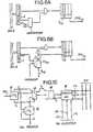
- Fig. 1gives a unidirectional representation where the inputs i and the outputs o have been separated.
- the TSE, pforms a packet consisting of [j] to which we add the destination address qk then presents it to the switching network R. Using this address, the switching network directs the packet to the TSE oq .
- the TSEoqinserts [j] into channel k of the MUXqq.
- the address qkis supplied by a command memory, local to the TSE, p and addressed using j. It is an input command, economical in memory capacity as we will see later, and very suitable for point-to-point communications (pj ⁇ qk) and merge communications in which several requesters are connected to a single request pj, p'j ', p "j" ⁇ qk. However, this control mode is unsuitable for broadcast connections in which a single caller is connected to a plurality of callers.
- the TSE ipadds to j the value p of the incoming main multiplex line to form a packet of labels pj which it broadcasts to all the TSE o .
- This control modeis very suitable for broadcast connections pj ⁇ qk, q'k ', q "k"; on the other hand, it is very costly in terms of control memory capacity as will be seen later.
- the inventionaims to provide a time division multiplex switching network for an asynchronous digital transmission network which is capable of broadcast switching, merge switching and point-to-point switching, and yet is economical in terms of capacity. memory.
- a time division multiplex switching network for an asynchronous digital transmission networkis as defined in claim 1.
- the TSEsaccept or do not accept packets.
- the first wordindicates a point-to-point or merge communication
- the second and third wordsare then respectively q and k and relate only to the TSEqq.
- the TSE othen ignore the second word but on the other hand. they use the third word to address each, their own control memory which gives them, if necessary, the number of the outgoing asynchronous channel.
- Chapter 1describes in general the structures and Chapter II describes in general the operation.
- Asynchronous time multiplexingconsists of a time interleaving of "frames each consisting of an" information sequence and a "label".
- the "frames”, "sequences and” labels"have a fixed length, for example 1024, 1016 and 8 bits respectively.
- the sequenceis a series of bits which belong to an asynchronous AC time channel identified locally in the multiplex, by the label.
- Fig. 2represents three sequences which belong to AC n ° 5 and one sequence to AC n ° 7.
- Transporting the label with the sequenceeliminates the need for a periodic time pattern or arrangement to identify a CA. This means that its speed is simply proportional to the average number of frames per unit of time and that it can therefore be arbitrary.
- bit rateFor example, with sequences of 1016 bits, the bit rate can be:
- the role of the switching networkis to establish, maintain and then release connections between incoming and outgoing ACs supported by the main multiplex lines that it connects.
- connection between the AC i of an incoming multiplex main line p (MUX, p) and the AC k of an outgoing main multiplex line q (MUX o q)consists, in the switching network, of transmitting on MUX o q all label frames j received on MUX ip after changing j and k.
- the UCX switching unit(Fig. 4)
- TSE i and TSE o switching terminal equipmentlinked together by a bus B which constitutes the switching network proper and to which the MUXs are connected.
- the routing of the frames in the UCXcan be carried out according to two methods: by the output or by the input.
- bus Bconcentrates the incoming bit rates.
- the marker MQwritten: 0, q, k, at the address j of the control memory CS, p.
- the MQerases by writing "hexadecimal FF in the corresponding words of the command memory (s).
- the busdistributes packets from TSE i to all TSE o .
- All outgoing switching terminal equipmentis permanently listening on the bus and, at any one time, there is only one incoming switching terminal equipment which is active, the others having an inactive logic state for the logical OR function.
- the overall bus speed of 1.3 Gb / sis sold by 8 lines at 165 Mb / s working in parallel.
- the bushas a line for the sampling clock and a line for the end of packet signal Fb.
- Each of the 10 lines in this bundleresponds to a “diabolo” structure with 64 inputs and 64 outputs (Cf. Fig. 7) comprising 7 circuits type 100 101 which provide the logic OR function to a central point C from where 9 circuits type 100112 broadcast to the outputs.
- a centralized allocatorresolves access conflicts.
- This allocatorcan be of a known type. It includes (Fig. 8) a receiver 31 of the access requests from the different TSEs i which ensures the acquisition of the requests and the selection of one of them by cyclical exploration, a sequencing transmitter 32 which receives from the receiver 31 the information “request presented DA and the number N 'of the selected TSE i , transmits to the TSE IN , the emission right CAL, acknowledges the request towards the receiver, thus authorizing the search and the possible selection of a new access request, and permanently transmits to all TSEs, the HAL base clock for transmission on the bus.
- a minimum interval of one period of the HAL signalis observed between two sequences of HAL in order to take into account the transfer time vagaries on the bus as a function of the positions of the TSE, transmitter and of the TSE or o concerned.
- An internal clock H I 30controls the two preceding mechanisms.
- the TSE, preceives from an asynchronous serial multiplex main line of index p.
- IP MUXframes of pj labels and transmits on the bus, in the form of 8-bit parallel words, packets of type (D, x, y).
- a TSEconsists (Fig. 10) of an incoming multiplex terminal equipment 11 whose role is to separate, in the signal of the incoming multiplex MUX, the data constituting the sequence Di, the sampling clock Hi , and the frame synchronization signal Si, and generate the input sequencing.
- the input switching terminal equipment TSE, palso includes a control memory 12 of 256 words of 15 bits for the transformation pj ⁇ D, x, y provided with its access device to the marker, a set 13 ensuring the functions of parallel serial conversion of the incoming data, of multiplexing of the header [D, x, y] and of presentation to the queue 14.
- the input switching terminal equipmentcomprises a queue 14 ensuring, by storing 32-bit words, the rate change between the MUX ; and bus B, that is to say the reception of the incoming data provided with the header D, x, y at a rate Ri compatible with the bit rate of the incoming multiplex, the storage of 32 words of 32 bits necessary for the constitution of an entire packet intended to be transmitted on the bus, the memorization of the words belonging to the following sequences, likely to arrive on the TSE, during the waiting period for the authorization to transmit on the bus and the transmission of the data constituting a packet at a rate Ro compatible with that of the bus.
- the sending of a packet on the bus 15causes the sending to the allocator of the requests for access to the bus (DAL), the reception, in return, of the rhythm information (HAL) and of the authorization of send (CAL) and the synchronized transmission of signals on the bus: Db data, Hb clock and Fb packet end.
- DALallocator of the requests for access to the bus
- HALrhythm information
- CALauthorization of send
- the incoming multiplex terminal equipment 11is composed of a detection device 111 making it possible to extract from the composite signal, the NRZ Di data, the sampling clock Hi and the frame synchronization signal Si.
- the TSEuses the MANCHESTER II coding principle with slow clock in the absence of data described in "A local packet ring video communication network, the AMBER project ⁇ 3.2 JP COUDREUSE IDATE 81".
- a sequencing generator 112 reset to zero by frame synchronization Sidelivers, by counting Hi, to the sets 12 and 13 the necessary pulses.
- the numbers without particular punctuationare single action times
- the numbers in square bracketsindicate a time period with its limits included and the numbers in parentheses represent modulo 32 congruent pulses; example ( ⁇ ): all times p + 32 m (whole m).
- the control memory 12is composed of the memory circuits proper 121, that is to say 4 circuits 256 ⁇ 4 type 100422, connected in parallel, of a shift register of 24 bits, 122, with serial and parallel loading, and parallel reading, allowing to receive the writing orders coming from the marker and to contain the information to be returned after reading.
- This registercontains 8 address bits, 1 access type bit - read or write - and 15 bits of data read or write.
- the control memory 12also includes a control logic 123 ensuring the taking into account of the marker commands, the resolution of conflicts of access to the memory, the execution of the access requested by presentation of the address from the register 122, the positioning of the memory in read or write by opening the door 125, the recording of the data possibly read and the resetting of the wire M s signaling to the marker the end of the requested operation.
- the assembly 13includes a register serial conversion 8-bit parallel series receiving at the rate H ; the data D i .
- the incoming datais then recorded in 8-bit words at times (25) and (33) in registers 135 and 136 and, via the multiplexer 132, in registers 133 and 134 at times (9) and (17).
- the label jis recorded in a register 137 at time (9) and presented via the multiplexer 124 as an address to the control memory 121.
- the control memory 121being in ECL technology, the internal label D, x, y is available approximately 14 ⁇ s after the presentation of j, ie at time 14.
- the label D, x, yis loaded into registers 133 and 134 via the multiplexers 138 and 132. All times (33) all of the 32 bits of registers 133 to 136 being ready, a signal R ; presentation to the queue is generated.
- the queue 14is produced using an ECL RAM memory 141 of 256 words of 32 bits (i.e. 8 ECL circuits 256 x 4 type 100422) controlled by a management circuit 142 which generates the addresses and the read or write signal.
- ECL RAM memory 141of 256 words of 32 bits (i.e. 8 ECL circuits 256 x 4 type 100422) controlled by a management circuit 142 which generates the addresses and the read or write signal.
- An input register 143 and two output registers 144 and 145 of 32 bitseach provide the temporary memorizations necessary for the synchronization of the memory accesses, as a function of the asynchronous input and output requests R i and R o .
- the bus access block 15includes a sequencer 151, receiving from the management circuit 142 of the queue 142 the signal UB when an entire packet, stored in the queue, is ready to be transmitted without interruption at the rate of the bus .
- the sequencer 151On reception of the signal UB, the sequencer 151 generates a request for allocation of the DAL bus to the allocator.
- the allocatorsends to the TSE, the requester chooses the CAL authorization signal.
- the sequencerthen begins the transmission phase on the bus.
- the stack bottom wordavailable in the register 145, is stored in the output register 152 while a new output request is sent to the management circuit 142.
- This wordis then demultiplexed into 4 bytes in the register 153 via the multiplexer 154. and transmitted on the bus at the rate of HB derived from HAL.
- the reception assembly 21includes a time base 211 which, by counting H B , synchronized by F B delivers to the circuits 22 and 23 the necessary time references.
- Part Dx of the label is recorded at time 1 in the register 231, then the parameter x is compared in the comparator 212, with the number q of the TSE o contained in the register 213.
- the TSE oqis not affected by the frame being transmitted on the bus and, through gate 216, flip-flop 217 generates at time 4, the blocking signal of the time generator 211, and therefore of the reception mechanism.
- the two flip-flops 218 and 219make it possible to phase the end of packet signal transmitted on the bus and to re-synchronize the queue.
- control memory 22is composed of the memory circuits proper 221. either 2 circuits 256 x 4 type 100122 in parallel and a shift register of 17 bits 222 with loading in series and in parallel and parallel reading for dialogue with the marker.
- This register 222contains 8 bits of address 1 bit of access type and 8 bits of data.
- the control logic 223ensures synchronization, during the phase [1-4] of transformation a ⁇ k. marker accesses by positioning of the multiplexer 224 and action on the register 222 and the door 225.
- the assembly 23consists of 4 registers 231 to 234, loaded respectively at times (1) to (4). for switching from byte format on the bus, to 32-bit format in the queue.
- the multiplexer 236makes it possible to introduce into the register 231, at time 4. the label k of a broadcast communication whose code has been presented as an address to the control memory 221, 18 nanoseconds earlier.
- the queue 24is produced using a 32-bit 256-bit ECL RAM memory 241 241 (i.e. 8 circuits 256 x 4 type 100422) controlled by a management circuit 242.
- the registers 243, 244 and 245provide the memorizations necessary for asynchronous accesses on the order of the X signals ; and X o .
- the words making up the packetare multiplexed into bytes in the register 242 via the multiplexer 253, then output in series D o at the rate H o .
- the sequencerResynchronized by the outgoing end of packet signal FB o , the sequencer generates the frame synchronization T o intended for the outgoing multiplex terminal equipment 26.
Landscapes
- Engineering & Computer Science (AREA)
- Computer Networks & Wireless Communication (AREA)
- Signal Processing (AREA)
- Data Exchanges In Wide-Area Networks (AREA)
- Use Of Switch Circuits For Exchanges And Methods Of Control Of Multiplex Exchanges (AREA)
Description
Translated fromFrenchLa présente invention concerne un réseau de commutation multiplex à division du temps, du type asynchrone, destiné à commuter les données numériques appartenant à différents services de communications, tels que le téléphone, la transmission des données, la visiophonie, la télédistribution, etc.The present invention relates to a time division multiplex switching network, of the asynchronous type, intended for switching digital data belonging to different communication services, such as the telephone, data transmission, video telephony, cable television, etc.
Le principe de la commutation multiplex à division du temps de type asynchrone a déjà été décrit pour un réseau de commutation intégrant le téléphone et la transmission de données, raccordé à des lignes principales multiplex à trames hybrides, c'est-à-dire dont la trame définit des circuits et des paquets (cf. demande de brevet européen EP-A-0 059 149 déposée le 19 février 1982). Ce réseau de commutation est constitué par des équipements terminaux de commutation, TSE, reliés d'une part aux liaisons multiplex principales et d'autre part à un réseau de commutation proprement dit.The principle of asynchronous time division multiplex switching has already been described for a switching network integrating the telephone and the data transmission, connected to main multiplex lines with hybrid frames, that is to say the frame defines circuits and packets (cf. European patent application EP-A-0 059 149 filed on February 19, 1982). This switching network consists of terminal switching equipment, TSE, connected on the one hand to the main multiplex links and on the other hand to a switching network proper.
La Fig. 1 donne une représentation unidirectionnelle où les entrées i et les sorties o ont été séparées. Pour commuter le contenu [j] de la voie temporelle asynchrone entrante j, de la liaison multiplex MUXip à la voie temporelle asynchrone sortante k de la liaison multiplex sortante MUXqq, le TSE,p forme un paquet constitué par [j] auquel on ajoute l'adresse de destination qk puis le présente au réseau de commutation R. A l'aide de cette adresse, le réseau de commutation aiguille le paquet vers le TSEoq. Le TSEoq insère [j] dans la voie k du MUXqq.Fig. 1 gives a unidirectional representation where the inputs i and the outputs o have been separated. To switch the content [j] of the asynchronous incoming time channel j, of the multiplex link MUXip to the outgoing asynchronous time channel k of the outgoing multiplex link MUXqq, the TSE, p forms a packet consisting of [j] to which we add the destination address qk then presents it to the switching network R. Using this address, the switching network directs the packet to the TSEoq . The TSEoq inserts [j] into channel k of the MUXqq.
L'adresse qk est fournie par une mémoire de commande, locale au TSE,p et adressée à l'aide de j. Il s'agit d'une commande par l'entrée, économique en capacité de mémoire comme on le verra par la suite, et très adaptée aux communications point à point (pj→qk) et aux communications de fusion dans lesquelles plusieurs demandeurs sont connectés à un demandé unique pj, p'j', p"j" → qk. En revanche, ce mode de commande est inadapté aux connexions de diffusion dans lesquelles un seul demandeur est connecté à une pluralité de demandés.The address qk is supplied by a command memory, local to the TSE, p and addressed using j. It is an input command, economical in memory capacity as we will see later, and very suitable for point-to-point communications (pj → qk) and merge communications in which several requesters are connected to a single request pj, p'j ', p "j" → qk. However, this control mode is unsuitable for broadcast connections in which a single caller is connected to a plurality of callers.
La commande peut, au contraire, s'effectuer par la sortie. Dans ce cas, l'TSEip ajoute à j la valeur p de la ligne principale multiplex entrante pour former un paquet d'étiquettes pj qu'il diffuse vers tous les TSEo. Chacun d'eux, par exemple, TSEoq, adresse par pj une mémoire de commande qui lui est locale et en déduit le cas échéant, la valeur k de l'étiquette de sortie. Ce mode de commande est très adapté aux connexions de diffusion pj → qk, q'k', q"k" ; en contrepartie, il est très coûteux en capacité de mémoire de commande comme on le verra par la suite.On the contrary, the order can be made through the outlet. In this case, the TSEip adds to j the value p of the incoming main multiplex line to form a packet of labels pj which it broadcasts to all the TSEo . Each of them, for example, TSEo q, addresses by pj a control memory which is local to it and deduces therefrom if necessary, the value k of the output label. This control mode is very suitable for broadcast connections pj → qk, q'k ', q "k"; on the other hand, it is very costly in terms of control memory capacity as will be seen later.
L'invention vise à réaliser un réseau de commutation multiplex à division du temps pour réseau de transmission numérique asynchrone qui soit apte à la commutation de diffusion, à la commutation de fusion et à la commutation point à point, et soit cependant économique en capacité de mémoire.The invention aims to provide a time division multiplex switching network for an asynchronous digital transmission network which is capable of broadcast switching, merge switching and point-to-point switching, and yet is economical in terms of capacity. memory.
Conformément à l'invention, un réseau de commutation multiplex à division du temps pour réseau de transmission numérique asynchrone est tel que défini dans la revendication 1.According to the invention, a time division multiplex switching network for an asynchronous digital transmission network is as defined in
Selon la valeur des trois mots qui composent l'identificateur, les TSE, acceptent ou n'acceptent pas les paquets.Depending on the value of the three words that make up the identifier, the TSEs accept or do not accept packets.
Si le premier mot indique une communication point à point ou de fusion, on se trouve dans le cas de la commande par l'entrée. Les deuxième et troisième mots sont alors respectivement q et k et ne concernent que le TSEqq.If the first word indicates a point-to-point or merge communication, we are in the case of the command by the input. The second and third words are then respectively q and k and relate only to the TSEqq.
Si le premier mot indique une connexion de diffusion, on se trouve dans le cas de la commande par la sortie. Les TSEo ignorent alors le deuxième mot mais en revanche. ils exploitent le troisième mot pour adresser chacun, leur propre mémoire de commande qui leur donne, le cas échéant, le numéro de la voie asynchrone sortante.If the first word indicates a broadcast connection, we are in the case of output control. The TSEo then ignore the second word but on the other hand. they use the third word to address each, their own control memory which gives them, if necessary, the number of the outgoing asynchronous channel.
L'invention va être maintenant décrite en détail en relation avec les dessins annexés dans lesquels :
- la Fig. 1 se rapporte à un réseau de commutation temporel asynchrone de l'art antérieur et a été explicité dans l'entrée en matière ;
- la Fig. 2 représente le principe d'un réseau de transmission multiplex temporel asynchrone ;
- la Fig. 3 représente l'organisation générale du réseau de commutation ;
- la Fig. 5 donne l'organisation fonctionnelle de l'équipement terminal de commutation d'entrée TSE,;
- les Figs. 6A et 6B donnent l'organisation des équipements terminaux de commutation de sortie TSEo ;
- la Fig. 7 représente la structure matérielle du bus ;
- la Fig. 8 représente le schéma fonctionnel de l'allocateur du bus ;
- la Fig. 9 présente les formes d'onde des signaux relatifs au bus ;
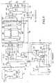
- la Fig. 10 représente sous la forme d'un diagramme de blocs les TSE, ;
- la Fig. 11 donne la structure complète des TSE, ;
- la Fig. 12 représente sous la forme d'un diagramme de blocs les TSEo ;
- la Fig. 13 donne la structure complète des TSEo ;
- Fig. 1 relates to an asynchronous time switching network of the prior art and has been explained in the introduction;
- Fig. 2 shows the principle of an asynchronous time multiplex transmission network;
- Fig. 3 represents the general organization of the switching network;
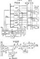
- Fig. 5 gives the functional organization of the input switching terminal equipment TSE;
- Figs. 6A and 6B give the organization of the terminal equipment for switching output TSEo ;
- Fig. 7 shows the hardware structure of the bus;
- Fig. 8 shows the block diagram of the bus allocator;
- Fig. 9 shows the waveforms of the signals relating to the bus;
- Fig. 10 shows in the form of a block diagram the TSEs;
- Fig. 11 gives the complete structure of the TSE;
- Fig. 12 shows in the form of a block diagram the TSEo ;
- Fig. 13 gives the complete structure of the TSEo ;
Le chapitre 1 décrit d'une façon générale les structures et le chapitre Il décrit d'une façon générale le fonctionnement.
Un multiplexage temporel asynchrone consiste en un entrelacement temporel de « trames constituées chacune d'une « séquence d'information et d'une « étiquette ».Asynchronous time multiplexing consists of a time interleaving of "frames each consisting of an" information sequence and a "label".
Les « trames », « séquences et « étiquettes » ont une longueur fixe, par exemple respectivement 1 024, 1 016 et 8 bits.The "frames", "sequences and" labels "have a fixed length, for example 1024, 1016 and 8 bits respectively.
La séquence est une suite de bits qui appartiennent à une voie temporelle asynchrone AC repérée localement dans le multiplex, par l'étiquette. La Fig. 2 représente trois séquences qui appartiennent à l'AC n° 5 et une séquence à l'AC n° 7.The sequence is a series of bits which belong to an asynchronous AC time channel identified locally in the multiplex, by the label. Fig. 2 represents three sequences which belong to AC n ° 5 and one sequence to AC n ° 7.
Le transport de l'étiquette avec la séquence supprime la nécessité d'un motif ou arrangement temporel périodique pour identifier une AC. Ceci entraîne que son débit est simplement proportionnel au nombre moyen de trames par unité de temps et qu'il peut donc être quelconque.Transporting the label with the sequence eliminates the need for a periodic time pattern or arrangement to identify a CA. This means that its speed is simply proportional to the average number of frames per unit of time and that it can therefore be arbitrary.
Par exemple, avec des séquences de 1 016 bits, le débit peut être de :
Un exemple de synchronisation au niveau bit et au niveau trames par un séparateur est donné dans la description des TSE (Cf. § II, 22a).An example of bit-level and frame-level synchronization by a separator is given in the description of the TSEs (Cf. § II, 22a).
Le réseau de commutation a pour rôle d'établir, maintenir puis relâcher des connexions entre des AC entrantes et sortantes supportées par les lignes principales multiplex qu'il raccorde.The role of the switching network is to establish, maintain and then release connections between incoming and outgoing ACs supported by the main multiplex lines that it connects.
La connexion entre l'ACi d'une ligne principale multiplex entrante p (MUX,p) et l'ACk d'une ligne principale multiplex sortante q (MUXoq) consiste, dans le réseau de commutation, à émettre sur MUXoq toutes les trames d'étiquette j reçues sur MUXip après avoir changé j et k.The connection between the ACi of an incoming multiplex main line p (MUX, p) and the ACk of an outgoing main multiplex line q (MUXo q) consists, in the switching network, of transmitting on MUXo q all label frames j received on MUXip after changing j and k.
Le réseau de commutation se compose de deux sous-ensembles :
- - l'unité de commutation UCX, qui raccorde les lignes principales multiplex MUXo à MUXn (entrantes vers sortantes) et qui est chargée du démultiplexage, de l'aiguillage puis du multiplexage des trames ;
- - le marqueur MQ qui commande l'établissement et la rupture des connexions à l'intérieur de l'UCX et qui, à cette fin est raccordé :
- à l'UCX par un accès spécialisé de marquage M ;
- aux MUXiO et MUXoO pour échanger les ordres de connexion.
- - the UCX switching unit, which connects the main multiplex lines MUXo to MUXn (incoming to outgoing) and which is responsible for demultiplexing, routing and then multiplexing of the frames;
- - the MQ marker which controls the establishment and rupture of connections inside the UCX and which, for this purpose is connected:
- to the UCX by a specialized M marking access;
- to MUXiO and MUXoO to exchange connection orders.
Elle est constituée des équipements terminaux de commutation TSEi et TSEo reliés entre eux par un bus B qui constitue le réseau de commutation proprement dit et auxquels sont raccordés les MUX.It consists of the TSEi and TSEo switching terminal equipment linked together by a bus B which constitutes the switching network proper and to which the MUXs are connected.
L'aiguillage des trames dans l'UCX peut s'effectuer selon deux méthodes : par la sortie ou par l'entrée.The routing of the frames in the UCX can be carried out according to two methods: by the output or by the input.
commande par la sortie :
- A chaque trame entrante, les TSEi ajoutent au numéro j de l'AC, le numéro p du MUX,, puis émettent sur le bus, le paquet ainsi formé. L'étiquette globale jp est alors décodée par tous les TSEo pour reconnaître les trames qui les concernent. A cette fin, on utilise dans chaque TSEo, une mémoire de commande CSo qui, pour chaque valeur de jp, indique si la trame doit être acceptée en donnant le cas échéant, la nouvelle valeur k de l'AC.
- With each incoming frame, the TSEsi add to the number j of the AC, the number p of the MUX, then transmit on the bus, the packet thus formed. The global label jp is then decoded by all the TSEso to recognize the frames which concern them. To this end, a control memory CSo is used in each TSEo which, for each value of jp, indicates whether the frame must be accepted by giving, if necessary, the new value k of the AC.
Cette organisation est très adaptée aux communications de diffusion puisque plusieurs TSEo peuvent accepter le même paquet, mais en contrepartie, elle est coûteuse en mémoire : si l'UCX raccorde n MUX de N AC, chaque CSo a une capacité de n N mots de log2 N bits, soit au total pour n CSo : n2N log2 N bits : c'est-à-dire une capacité globale proportionnelle au carré du nombre des lignes principales multiplex. Avec n = 64 et N = 256 on obtient 8 388 608 bits.This organization is very suitable for broadcast communications since several TSEo can accept the same packet, but in return, it is costly in memory: if the UCX connects n MUX of N AC, each CSo has a capacity of n N words of log2 N bits, ie in total for n CSo : n2 N log2 N bits: that is to say an overall capacity proportional to the square of the number of main multiplex lines. With n = 64 and N = 256 we obtain 8,388,608 bits.
commande par l'entrée :
- Pour chaque trame entrante, les TSE, remplacent j par le numéro global kq de la sortie, grâce à une mémoire de commande CSi. Ensuite, ils émettent sur le bus le paquet qui ne sera accepté que par le TSEo de numéro q, c'est-à-dire TSEoq.
- For each incoming frame, the TSEs, replace j by the global number kq of the output, thanks to a control memory CSi . Then, they send the packet on the bus which will only be accepted by the TSEo of number q, ie TSEo q.
Cette méthode d'aiguillage ne requiert au total que N mots de log2 n N bits par CS, soit nN log2Nn bits pour l'UCX, c'est-à-dire une capacité simplement proportionnelle au nombre de MUX, soit 229 376 bits avec n = 64 et n = 256. En revanche, elle est adaptée aux communications de fusion.This referral method requires only a total of N log words2 n N bits per CS, i.e. nN log2 Nn bits for the UCX, i.e. a capacity simply proportional to the number of MUXs, i.e. 229 376 bits with n = 64 and n = 256. However, it is suitable for merge communications.
La commande retenue dans l'invention, et décrite ci-dessous, est mixte : elle se répartit entre l'entrée et la sortie, ce qui permet d'effectuer des communications de diffusion tout en limitant le volume des mémoires à environ 400 000 bits (pour n = 64 et N = 256).The command retained in the invention, and described below, is mixed: it is distributed between the input and the output, which makes it possible to carry out broadcast communications while limiting the volume of the memories to approximately 400,000 bits (for n = 64 and N = 256).
Son débit est égal au produit du débit des MUX entrants par leur taux de charge. En d'autres termes, le bus B concentre les débits entrants.Its flow is equal to the product of the flow of incoming MUXs by their load rate. In other words, bus B concentrates the incoming bit rates.
Ils assurent les fonctions suivantes :
- - la réception série de trames au débit instantané de la ligne principale multiplex entrante MUXip ;
- - à l'aide d'une mémoire de commande CSip, le transcodage de l'étiquette j de 8 bits en un identificateur de 15 bits, interne au commutateur, et destiné à être décodé dans les TSEo : cet identificateur de 15 bits comprend un bit D, 6 bits x
et 8 bits y.
- - the serial reception of frames at the instantaneous rate of the incoming main multiplex line MUXip ;
- - using a command memory CSip , transcoding of the 8-bit label j into a 15-bit identifier, internal to the switch, and intended to be decoded in the TSEo : this 15-bit identifier includes a bit D, 6 bits x and 8 bits y.
D indique la nature de la communication :
- si D = 0, il s'agit d'une communication point à point (pj → qk) ou de fusion :

- Alors : x = q numéro du MUXo, q E [0,63] et = k numéro de l'AC sortante, k E [0,255]
- si D = 1, il s'agit d'une communication de diffusion (pj → qk, q'k', q"k").
- x n'a pas de signification.

- a est, dans le cas de la communication de diffusion :

- le mot d'adresse a dans CSoq est k
- le mot d'adresse a dans CSoq' est k'
- le mot d'adresse a dans CSoq" est k".


- if D = 0, it is a point-to-point (pj → qk) or merge communication:
- Then: x = q number of the MUXo , q E [0.63] and = k number of the outgoing CA, k E [0.255]
- if D = 1, it is a broadcast communication (pj → qk, q'k ', q "k").
- x has no meaning.
- a is, in the case of broadcast communication:
- the address word a in CSoq is k
- the address word a in CSo q 'is k'
- the address word a in CSoq "is k".
Mise en file Fip. Cette file est destinée à :
- - attendre la disponibilité du bus B ;
- - effectuer le changement de cadence de bits entre MUXi et B.
- - avec l'autorisation de l'allocateur A (Fig. 4), émettre sur le bus B le paquet (séquence + identificateur) situé en fond de file.
- - wait for the availability of bus B;
- - change the bit rate between MUXi and B.
- - with the authorization of allocator A (Fig. 4), send the packet (sequence + identifier) located on the back of the queue on bus B.
Ils analysent les identificateurs de tous les paquets transmis sur le bus pour trier ceux qui doivent être aiguillés vers leur MUXo qui leur est associé :
- si D = 0 (Fig. 6A), le TSEo compare la variable x à la quantité q. Si x = q, il range la séquence et l'étiquette y = k dans la file Foq.
- si D = 1 (Fig. 6B) TSEo utilise y pour adresser les mémoires de commande CSoq, CSoq, CSoq" :
- s'il existe une connexion, TSEoq fournit la valeur k de l'étiquette sortante et autorise le rangement dans la file Foq ;
- s'il n'existe pas de connexion, TSEoq fournit un code particulier (par exemple 1111 1111) qui interdit l'accès à Foq.
- - émission en série sur MUXoq des trames situées en fond de file Foq. Celle-ci est destinée à : effectuer le changement de débit instantané entre B et MUXoq ;
stocker une éventuelle série de trames arrivées quasi instantanément de plusieurs MUX,.
- if D = 0 (Fig. 6A), the TSEo compares the variable x with the quantity q. If x = q, it stores the sequence and the label y = k in the queue Foq .
- if D = 1 (Fig. 6B) TSEo uses y to address the control memories CSoq , CSoq , CSoq " :
- if there is a connection, TSEoq supplies the value k of the outgoing label and authorizes storage in the queue Fo q;
- if there is no connection, TSEoq provides a specific code (for example 1111 1111) which prevents access to Fo q.
- - serial transmission on MUXoq of the frames located at the bottom of the queue Fo q. This is intended to: perform the instantaneous flow change between B and MUXo q;
store a possible series of frames arriving almost instantaneously from several MUXs.
Chaque CSi et chaque CSo a respectivement une capacité de 256 x 15 bits et 256 x 8 bits, soit au total 256 (15 + 8) x 64 = 376 832 bits pour un réseau de commutation de 64 lignes principales multiplex de 256 voies asynchrones chacun.Each CSi and each CSo has respectively a capacity of 256 x 15 bits and 256 x 8 bits,i.e. a total of 256 (15 + 8) x 64 = 376 832 bits for a switching network of 64 main lines, multiplex of 256 channels asynchronous each.
C'est un processeur qui établit ou relâche les connexions en « marquant » les mémoires de commande CSi et CSo conformément à des ordres de connexion qu'il reçoit sur le MUXiO dont il accuse réception sur le MUXoO.It is a processor which establishes or drops the connections by "marking" the control memories CSi and CSo in accordance with connection orders which it receives on the MUXiO of which it acknowledges receipt on the MUXoO .
Le marqueur MQ inscrit : 0, q, k, à l'adresse j de la mémoire de commande CS,p.The marker MQ written: 0, q, k, at the address j of the control memory CS, p.
Par les liaisons Mip, Mip, Mip", le marqueur MQ inscrit :
- O, q, k, à l'adresse j de CSip
- 0, q, k, à l'adresse j' de CSip.
- 0, q, k, à l'adresse j" de CSip"
- O, q, k, at address j of CSip
- 0, q, k, at address j 'of CSip .
- 0, q, k, at address j "from CSip"
Par la liaison Mip, le MO inscrit : 1, rien, a à l'adresse j de CS,p et par les liaisons Moq, Moq, Moq, il écrit :
- k à l'adresse α de CSoq
- k' à l'adresse α de CSoq
- k" à l'adresse α de CSoq
- k at the address α of CSoq
- k 'at the address α of CSoq
- k "at the address α of CSoq
Pour relâcher les connexions, le MQ efface par écriture de « FF hexadecimal dans les mots correspondants de la ou des mémoires de commande.To release the connections, the MQ erases by writing "hexadecimal FF in the corresponding words of the command memory (s).
Le bus assure la diffusion des paquets issus des TSEi vers tous les TSEo.The bus distributes packets from TSEi to all TSEo .
Tous les équipements terminaux de commutation sortants sont en permanence à l'écoute sur le bus et, à tout instant, il n'y a qu'un seul équipement terminal de commutation entrant qui soit actif, les autres présentant un état logique inactif pour la fonction OU logique.All outgoing switching terminal equipment is permanently listening on the bus and, at any one time, there is only one incoming switching terminal equipment which is active, the others having an inactive logic state for the logical OR function.
Le débit global du bus de 1,3 Gb/s est écoulé par 8 lignes à 165 Mb/s travaillant en parallèle.The overall bus speed of 1.3 Gb / s is sold by 8 lines at 165 Mb / s working in parallel.
Le bus comporte une ligne pour l'horloge d'échantillonnage et une ligne pour le signal de fin de paquet Fb.The bus has a line for the sampling clock and a line for the end of packet signal Fb.
Chacune des 10 lignes de ce faisceau répond à une structure type « diabolo à à 64 entrées et 64 sorties (Cf. Fig. 7) comportant 7 circuits type 100 101 qui assurent la fonction OU logique jusqu'à un point central C d'où 9 circuits type 100112 effectuent la diffusion vers les sorties.Each of the 10 lines in this bundle responds to a “diabolo” structure with 64 inputs and 64 outputs (Cf. Fig. 7) comprising 7 circuits type 100 101 which provide the logic OR function to a central point C from where 9 circuits type 100112 broadcast to the outputs.
Pour n'accorder le droit d'émettre qu'à un seul TSEi à la fois, un allocateur centralisé résout les conflits d'accès. Cet allocateur peut être d'un type connu. Il comprend (Fig. 8) un récepteur 31 des demandes d'accès issues des différents TSEi qui assure l'acquisition des demandes et la sélection de l'une d'elles par exploration cyclique, un émetteur de séquencement 32 qui reçoit du récepteur 31 l'information « demande présentée DA et le numéro N' du TSEi sélecté, émet à destination du TSEIN, le droit d'émission CAL, acquitte la demande vers le récepteur, autorisant ainsi la recherche et la sélection éventuelle d'une nouvelle demande d'accès, et émet en permanence vers tous les TSE, l'horloge de base HAL pour l'émission sur le bus.To grant the right to transmit to only one TSEi at a time, a centralized allocator resolves access conflicts. This allocator can be of a known type. It includes (Fig. 8) a
Ces différents signaux répondent au diagramme des temps de la Fig. 9.These different signals respond to the time diagram in FIG. 9.
Un intervalle minimal d'une période du signal HAL est observé entre deux séquences de HAL afin de tenir compte des aléas de temps de transfert sur le bus en fonction des positions du TSE, émetteur et du ou des TSEo concernés.A minimum interval of one period of the HAL signal is observed between two sequences of HAL in order to take into account the transfer time vagaries on the bus as a function of the positions of the TSE, transmitter and of the TSE oro concerned.
Une horloge interne HI 30 pilote les deux mécanismes précédents.An
Le TSE,p reçoit d'une ligne principale multiplex série asynchrone d'indice p. MUXIP, des trames d'étiquettes pj et émet sur le bus, sous forme de mots parallèles de 8 bits, des paquets de type (D, x, y).The TSE, p receives from an asynchronous serial multiplex main line of index p.IP MUX, frames of pj labels and transmits on the bus, in the form of 8-bit parallel words, packets of type (D, x, y).
Un TSE, se compose (Fig. 10) d'un équipement terminal de multiplex entrant 11 dont le rôle est de séparer, dans le signal du multiplex entrant MUX,, les données constitutives de la séquence Di, l'horloge d'échantillonnage Hi, et le signal de synchronisation de trame Si, et de générer le séquencement d'entrée.A TSE, consists (Fig. 10) of an incoming
L'équipement terminal de commutation d'entrée TSE,p comprend aussi une mémoire de commande12 de 256 mots de 15 bits pour la transformation pj → D, x, y munie de son dispositif d'accès au marqueur, un ensemble 13 assurant les fonctions de conversion série parallèle des données entrantes, de multiplexage de l'en-tête [D, x, y] et de présentation à la file d'attente 14.The input switching terminal equipment TSE, p also includes a control memory12 of 256 words of 15 bits for the transformation pj → D, x, y provided with its access device to the marker, a
Enfin, l'équipement terminal de commutation d'entrée comprend une file d'attente 14 assurant, par stockage de mots de 32 bits, le changement de cadence entre le MUX; et le bus B, c'est-à-dire la réception des données entrantes munies de l'en-tête D, x, y à un rythme Ri compatible avec la cadence-bit du multiplex entrant, le stockage de 32 mots de 32 bits nécessaires à la constitution d'un paquet entier destiné à être émis sur le bus, la mémorisation des mots appartenant à des séquences suivantes, susceptibles d'arriver sur le TSE, pendant la période d'attente de l'autorisation d'émettre sur le bus et l'émission des données constitutives d'un paquet à un rythme Ro compatible avec celui du bus.Finally, the input switching terminal equipment comprises a
L'envoi d'un paquet sur le bus 15 provoque l'envoi vers l'allocateur des demandes d'accès au bus (DAL), la réception, en retour, des informations de rythme (HAL) et de l'autorisation d'émettre (CAL) et l'émission synchronisée des signaux sur le bus : Données Db, Horloge Hb et Fin de paquet Fb.The sending of a packet on the
L'équipement terminal de multiplex entrant 11 se compose d'un dispositif de détection 111 permettant d'extraire du signal composite, les données NRZ Di, l'horloge d'échantillonnage Hi et le signal de synchronisation de trame Si. Le TSE; exploite par exemple le principe de codage MANCHESTER Il avec horloge lente en l'absence de données décrit dans « Un réseau local de vidéocommunications en anneau à commutation de paquets, le projet AMBRE § 3.2 JP COUDREUSE IDATE 81 ».The incoming
Un générateur de séquencement 112 remis à zéro par la synchronisation de trame Si délivre par comptage de Hi, aux ensembles 12 et 13 les impulsions nécessaires.A
En ce qui concerne la notation des temps entre deux remises à zéro du générateur de séquencement 112, les nombres sans ponctuation particulière sont des temps d'action unique, les nombres entre crochets indiquent une période de temps avec ses limites incluses et les nombres entre parenthèses représentent des impulsions congruentes modulo 32 ; exemple (β) : tous les temps p + 32 m (m entier).Regarding the notation of the times between two resets of the
La mémoire de commande 12 est composée des circuits de mémoire proprement dits 121, soit 4 circuits 256 x 4 type 100422, montés en parallèle, d'un registre à décalage de 24 bits, 122, à chargement série et parallèle, et lecture parallèle, permettant de recevoir les ordres d'écriture issus du marqueur et de contenir les informations à retourner après lecture. Ce registre contient 8 bits d'adresse, 1 bit de type de l'accès - lecture ou écriture - et 15 bits de données lues ou à écrire.The
L'ensemble des liaisons M avec le marqueur se décomposent en :
- - une liaison Mq de chargement série du registre 122 ;
- - une liaison M, de lecture série du registre 122 ;
- - une liaison Mh d'horloge ;
- - une liaison Ms de synchronisation des échanges.
- - a link Mq for serial loading of the register 122;
- - A link M, for serial reading of register 122;
- - a clock link Mh ;
- - a link Ms for synchronizing exchanges.
La mémoire de commande 12 comporte également une logique de commande 123 assurant la prise en compte des ordres du marqueur, le règlement des conflits d'accès à la mémoire, l'exécution de l'accès demandé par présentation de l'adresse issue du registre 122, le positionnement de la mémoire en lecture ou écriture par ouverture de la porte 125, l'enregistrement des données éventuellement lues et la remise à zéro du fil Ms signalant au marqueur la fin de l'opération demandée.The
L'ensemble 13 comporte un registre 131 de conversion série parallèle à 8 bits recevant au rythme H; les données Di. Les données entrantes sont ensuite enregistrées par mots de 8 bits aux temps (25) et (33) dans les registres 135 et 136 et, via le multiplexeur 132, dans les registres 133 et 134 aux temps (9) et (17).The
D'autre part, en début de réception de trame, l'étiquette j est enregistrée sur un registre 137 au temps (9) et présenté via le multiplexeur 124 comme adresse à la mémoire de commande 121.On the other hand, at the start of frame reception, the label j is recorded in a
La mémoire de commande 121 étant en technologie ECL, l'étiquette interne D, x, y est disponible environ 14 µs après la présentation de j, soit au temps 14.The
Aux temps (31) et (33), l'étiquette D, x, y est chargée dans les registres 133 et 134 via les multiplexeurs 138 et 132. Tous les temps (33) l'ensemble des 32 bits des registres 133 à 136 étant prêt, un signal R; de présentation à la file d'attente est généré.At times (31) and (33), the label D, x, y is loaded into
Pour satisfaire les contraintes de débit, la file d'attente 14 est réalisée à l'aide d'une mémoire RAM ECL 141 de 256 mots de 32 bits (soit 8 circuits ECL 256 x 4 type 100422) contrôlée par une circuiterie de gestion 142 qui génère les adresses et le signal de lecture ou d'écriture.To satisfy the flow constraints, the
Un registre d'entrée 143 et deux registres de sortie 144 et 145 de 32 bits chacun assurent les mémorisations temporaires nécessaires à la synchronisation des accès mémoires, en fonction des demandes asynchrones d'entrée en file et de sortie Ri et Ro.An
Le bloc d'accès au bus 15 comporte un séquenceur 151, recevant du circuit de gestion 142 de la file d'attente 142 le signal UB lorsqu'un paquet entier, stocké en file, est prêt pour être émis sans interruption au rythme du bus.The
A la réception du signal UB, le séquenceur 151 génère vers l'allocateur une demande d'allocation du bus DAL.On reception of the signal UB, the
Lorsque cette requête est satisfaite, l'allocateur envoie vers le TSE, demandeur choisi le signal d'autorisation d'émettre CAL.When this request is satisfied, the allocator sends to the TSE, the requester chooses the CAL authorization signal.
A l'aide du rythme de l'horloge de base HAL reçu en permanence par tous les TSE,, le séquenceur entame alors la phase d'émission sur le bus.Using the rhythm of the basic clock HAL permanently received by all the TSEs, the sequencer then begins the transmission phase on the bus.
Par le signal Ro, le mot de fond de pile, disponible dans le registre 145, est mémorisé dans le registre de sortie 152 tandis qu'une demande de sortie nouvelle est envoyée au circuit de gestion 142.By the signal Ro , the stack bottom word, available in the
Ce mot est ensuite démultiplexé en 4 octets dans le registre 153 via le multiplexeur 154. et émis sur le bus au rythme de HB dérivé de HAL.This word is then demultiplexed into 4 bytes in the
Lorsque tous les mots du paquet sont émis, l'information fin de paquet (signal Fb) est émise sur le bus.When all the words in the packet are sent, the end of packet information (signal Fb) is sent on the bus.
Les portes 155, 156 et 157 validées pendant la phase d'émission, permettent, une fois celle-ci terminée de présenter sur le bus le zéro logique nécessaire au fonctionnement correct du OU logique, principe du bus.The
Le TSEoq reconnaît, parmi les paquets émis sur le bus ceux qui lui sont destinés personnellement pour les communications point à point, lorsque x = q et les paquets de diffusion dont il est co- destinataire, c'est-à-dire dont il a connaissance du code α. Puis il retransmet sur la ligne principale multiplex série asynchrone d'indice q qui lui est associée des trames d'étiquette qk.The TSEoq recognizes, among the packets sent on the bus, those which are personally intended for it for point-to-point communications, when x = q and the broadcast packets which it is co-recipient of, that is to say which it has knowledge of the α code. Then it retransmits on the main asynchronous serial multiplex line of index q which is associated with it frames of label qk.
Le TSEoq se compose (Fig. 12) :
- a) d'un ensemble de réception 21 assurant les discriminations d'étiquettes et la génération du séquencement qui s'ensuit.
- b) d'une mémoire de commande 22 de 256 mots de 8 bits pour la conversion α→ k, munie de son dispositif d'accès au marqueur.
- c)
d'un ensemble 23 assurant les fonctions de multiplexage de k et de présentation des données à la file d'attente. - d) d'une
file d'attente 24 qui assure, par stockage de mots de 32 bits, deux fonctions :- 1) le changement de cadence de bits entre le bus et la ligne principale multiplex sortante, à savoir la réception des trames munies de leur étiquette de sortie k, à un rythme Xi compatible avec leur transfert sur le bus et la sortie des trames vers le MUXo au rythme Xo issu de l'horloge de base.
- 2) la mise en attente de séries de paquets possibles, reçus « quasi-instantanément de TSE,s. c'est-à-dire éventuellement sans interruption au rythme bus Xi.
- e)
un circuit d'émission 25 qui assure la conversion parallèle-série et l'émission des trames sous la commande de l'horloge Ho de ligne principale multiplex sortante. - f) un équipement terminal de
multiplex sortant 26 permettant de générer un signal composite sur MUXo à partir des données sortantes Do, de l'horloge Ho et du signal de synchronisation de trame To.
- a) of a
reception assembly 21 ensuring the discrimination of labels and the generation of the sequencing which follows. - b) a
control memory 22 of 256 words of 8 bits for the α → k conversion, equipped with its access device to the marker. - c) a
set 23 providing the functions of multiplexing k and presenting the data to the queue. - d) a
queue 24 which performs two functions by storing 32-bit words:- 1) the change in bit rate between the bus and the outgoing main multiplex line, namely the reception of the frames provided with their output label k, at a rate Xi compatible with their transfer on the bus and the output of the frames to MUXo at rhythm Xo from the basic clock.
- 2) the putting on hold of possible series of packets, received “almost instantaneously from TSE, s. that is to say possibly without interruption at the rate bus Xi .
- e) a
transmission circuit 25 which performs the parallel-series conversion and the transmission of the frames under the control of the clock Ho of the outgoing main multiplex line. - f) an outgoing
multiplex terminal equipment 26 making it possible to generate a composite signal on MUXo from the outgoing data Do , the clock Ho and the frame synchronization signal To .
a) l'ensemble de réception 21 comporte une base de temps 211 qui, par comptage de HB, synchronisé par FB délivre aux circuits 22 et 23 les références temporelles nécessaires.a) the
Les temps entre parenthèses sont congruents modulo 4.The times in parentheses are congruent modulo 4.
La partie D, x de l'étiquette est enregistrée au temps 1 dans le registre 231, puis le paramètre x est comparé dans le comparateur 212, au numéro q du TSEo contenu dans le registre 213.Part D, x of the label is recorded at
Au temps 3 :
- - si cette comparaison est positive,
la bascule 214 délivre le signal PAP de caractérisation de communication point à point. - - si le paramètre D est égal à 1, la
bascule 215 délivre le signal DIF caractéristique d'une communication de diffusion.
- - If this comparison is positive, flip-
flop 214 delivers the point-to-point communication characterization signal PAP. - - If the parameter D is equal to 1, the flip-
flop 215 delivers the DIF signal characteristic of a broadcast communication.
Si ni l'une ni l'autre des ces conditions ne sont satisfaites, le TSEoq n'est pas concerné par la trame en cours de transmission sur le bus et, par l'intermédiaire de la porte 216, la bascule 217 génère au temps 4, le signal de blocage du générateur de temps 211, et donc du mécanisme de réception.If neither of these conditions are satisfied, the TSEoq is not affected by the frame being transmitted on the bus and, through gate 216, flip-flop 217 generates at
Les deux bascules 218 et 219 permettent de mettre en phase le signal fin de paquet transmis sur le bus et de re-synchroniser la file d'attente.The two flip-
b) la mémoire de commande 22 est composée des circuits mémoire proprement dits 221. soit 2 circuits 256 x 4 type 100122 en parallèle et d'un registre à décalage de 17 bits 222 à chargement en série et en parallèle et lecture parallèle pour dialogue avec le marqueur.b) the
Ce registre 222 contient 8 bits d'adresse 1 bit de type d'accès et 8 bits de données. La logique de commande 223 assure la synchronisation, lors de la phase [1-4] de transformation a → k. des accès marqueurs par positionnement du multiplexeur 224 et action sur le registre 222 et la porte 225.This
c) l'ensemble 23 se compose de 4 registres 231 à 234, chargés respectivement aux temps (1) à (4). pour le passage du format octet sur le bus, au format 32 bits dans la file d'attente.c) the
Lorsque ces 4 registres sont chargés, leur contenu est transféré au temps (5) dans le registre 235 pour être présenté à la cadence X, à la file d'attente 24.When these 4 registers are loaded, their content is transferred at time (5) to register 235 to be presented at rate X, to queue 24.
Le multiplexeur 236 permet d'introduire dans le registre 231, au temps 4. l'étiquette k d'une communication de diffusion dont le code a a été présenté comme adresse à la mémoire de commande 221, 18 nanosecondes plus tôt.The
d) la file d'attente 24 est réalisée à l'aide d'une mémoire RAM ECL de 256 mots de 32 bits 241 (soit 8 circuits 256 x 4 type 100422) contrôlée par une circuiterie de gestion 242.d) the
Les registres 243, 244 et 245 assurent les mémorisations nécessaires aux accès asynchrones sur ordre des signaux X; et Xo.The
e) le circuit d'émission 25 répond au fonctionnement suivant :
- Dès qu'un paquet est prêt à sortir, le circuit de gestion de file 242 génère le signal UBp.
- As soon as a packet is ready to go out, the
queue management circuit 242 generates the signal UBp.
Sous commande du séquenceur 251 piloté par l'horloge de base du multiplex sortant HMUXo, les mots constitutifs du paquet sont multiplexés en octets dans le registre 242 via le multiplexeur 253, puis sortis en série Do au rythme Ho.Under the control of the
Resynchronisé par le signal fin de paquet sortant FBo, le séquenceur génère la synchronisation de trame To à destination de l'équipement terminal de multiplex sortant 26.Resynchronized by the outgoing end of packet signal FBo , the sequencer generates the frame synchronization To intended for the outgoing
f) celui-ci forme, à partir des données NRZ, Do, un signal composite appliqué à MUXo qui contient en outre la cadence-bit Ho codé MANCHESTER Il et les périodes d'inter trames caractérisées par le rythme d'horloge lente HLo.f) this forms, from the NRZ data, Do , a composite signal applied to MUXo which also contains the bit rate Ho coded MANCHESTER Il and the interframe periods characterized by the clock rate slow HLo .
Claims (2)
characterized in that the label (j) of each incoming asynchronous channel is in the respective incoming switching terminal equipment (TSE,) converted by means of a control memory (CS;, 12) into an identifier (D, x, y) intended to be decoded in the outgoing switching terminal equipment and composed of three words, a first word (D) characterizing the kind of switching communication as being selecting from point-to-point switching in which a single calling party is to be switched to a single called party, concentration switching in which several calling parties are to be switched to a single called party, diffusion switching in which a single calling party is to be switched to several calling parties, a second word (x) selecting the number (q) of the addressed outgoing multiplex highway or not having any significance according to the first word value, and a third word (y) characterizing the number (k) of the addressed outgoing asynchronous channel, or the numbers (k, k', k") of several outgoing asynchronous channels in the case of a diffusing switching (D = 1), and in that means (21, 23) for decoding the identifier (D, x, y) are provided in each outgoing switching terminal equipment (TSEo) in order to allow, on the one hand, the recognition of the packets which are intended for said equipment as a function of the second and third words (x, y) of the identifier and, on the other hand, to a control memory (CSo, 22) in said equipment, to process the recognized packets as a function of the first word (d) characterizing the kind of the switching.
Applications Claiming Priority (2)
| Application Number | Priority Date | Filing Date | Title |
|---|---|---|---|
| FR8222122 | 1982-12-30 | ||
| FR8222122AFR2538984A1 (en) | 1982-12-30 | 1982-12-30 | SWITCH FOR MULTIDEBIT DIGITAL NETWORK WITH ASYNCHRONOUS TIME SWITCH ADAPTED TO VIDEOCOMMUTATIONS |
Publications (2)
| Publication Number | Publication Date |
|---|---|
| EP0126196A1 EP0126196A1 (en) | 1984-11-28 |
| EP0126196B1true EP0126196B1 (en) | 1987-06-16 |
Family
ID=9280720
Family Applications (1)
| Application Number | Title | Priority Date | Filing Date |
|---|---|---|---|
| EP83402566AExpiredEP0126196B1 (en) | 1982-12-30 | 1983-12-30 | Asynchronous time-division switching network for point-to-point, merging and broadcast communications |
Country Status (6)
| Country | Link |
|---|---|
| US (1) | US4566095A (en) |
| EP (1) | EP0126196B1 (en) |
| JP (1) | JPS59135954A (en) |
| CA (1) | CA1211824A (en) |
| DE (1) | DE3372156D1 (en) |
| FR (1) | FR2538984A1 (en) |
Families Citing this family (26)
| Publication number | Priority date | Publication date | Assignee | Title |
|---|---|---|---|---|
| US4905219A (en)* | 1983-09-22 | 1990-02-27 | Aetna Life Insurance Company | Three level distributed control for networking I/O devices |
| JPH0628361B2 (en)* | 1984-11-27 | 1994-04-13 | 国際電信電話株式会社 | Packet exchange method |
| US4651318A (en)* | 1984-11-30 | 1987-03-17 | At&T Bell Laboratories | Self-routing packets with stage address identifying fields |
| US4697262A (en)* | 1984-12-20 | 1987-09-29 | Siemens Aktiengesellschaft | Digital carrier channel bus interface module for a multiplexer having a cross-connect bus system |
| US4734907A (en)* | 1985-09-06 | 1988-03-29 | Washington University | Broadcast packet switching network |
| US4730305A (en)* | 1986-04-11 | 1988-03-08 | American Telephone And Telegraph Company, At&T Bell Laboratories | Fast assignment technique for use in a switching arrangement |
| FR2600481B1 (en)* | 1986-06-20 | 1988-08-26 | Kalfon Rene | ASYNCHRONOUS SORTING SYSTEM FOR SELF-ROUTING DIGITAL MESSAGES |
| US4817084A (en)* | 1986-10-16 | 1989-03-28 | Bell Communications Research, Inc. | Batcher-Banyan packet switch with output conflict resolution scheme |
| US4769811A (en)* | 1986-12-31 | 1988-09-06 | American Telephone And Telegraph Company, At&T Bell Laboratories | Packet switching system arranged for congestion control |
| US4769810A (en)* | 1986-12-31 | 1988-09-06 | American Telephone And Telegraph Company, At&T Bell Laboratories | Packet switching system arranged for congestion control through bandwidth management |
| ZA883232B (en)* | 1987-05-06 | 1989-07-26 | Dowd Research Pty Ltd O | Packet switches,switching methods,protocols and networks |
| FR2618624B1 (en)* | 1987-07-24 | 1992-04-30 | Michel Servel | HYBRID TIME MULTIPLEX SWITCHING SYSTEM WITH OPTIMIZED BUFFER MEMORY |
| EP0312628B1 (en)* | 1987-10-20 | 1993-12-29 | International Business Machines Corporation | High-speed modular switching apparatus for circuit and packet switched traffic |
| FR2623954B1 (en)* | 1987-11-27 | 1993-11-19 | Alcatel Cit | ELEMENT FOR SWITCHING DATA TRANSMITTED BY ASYNCHRONOUS TIME MULTIPLEXING |
| DE3742748A1 (en)* | 1987-12-17 | 1989-07-06 | Philips Patentverwaltung | COUPLING AND COUPLING CONTROL FOR A SWITCHING NODE OF A BROADBAND SWITCHING SYSTEM |
| JPH01177239A (en)* | 1988-01-06 | 1989-07-13 | Nec Corp | Packet concentrator and packet switching device |
| JP2667868B2 (en)* | 1988-04-06 | 1997-10-27 | 株式会社日立製作所 | Cell switching system |
| FR2635243B1 (en)* | 1988-08-05 | 1994-01-14 | Lmt Radio Professionnelle | PACKET SWITCHER FOR ASYNCHRONOUS DATA TRANSFER IN A DIGITAL TRANSMISSION NETWORK |
| IT1224493B (en)* | 1988-10-17 | 1990-10-04 | Cselt Centro Studi Lab Telecom | LABEL CONTROL AND SWITCHING INTERFACE FOR FAST SWITCHING OF ASYNCHRONOUS PACKAGE |
| JP2753294B2 (en)* | 1988-12-23 | 1998-05-18 | 株式会社日立製作所 | Packet congestion control method and packet switching device |
| JP2865706B2 (en)* | 1989-05-31 | 1999-03-08 | 株式会社日立製作所 | Switching system |
| GB9019340D0 (en)* | 1990-09-05 | 1990-10-17 | Plessey Telecomm | An asynchronous transfer mode switching arrangement providing broadcast transmission |
| FR2670972A1 (en)* | 1990-12-20 | 1992-06-26 | Lmt Radio Professionelle | TRANSIT SWITCH OF AN ASYNCHRONOUS NETWORK, IN PARTICULAR AN ATM NETWORK. |
| SE515275C2 (en)* | 1992-12-14 | 2001-07-09 | Ericsson Telefon Ab L M | packet data network |
| US6473404B1 (en) | 1998-11-24 | 2002-10-29 | Connect One, Inc. | Multi-protocol telecommunications routing optimization |
| US6016307A (en) | 1996-10-31 | 2000-01-18 | Connect One, Inc. | Multi-protocol telecommunications routing optimization |
Family Cites Families (6)
| Publication number | Priority date | Publication date | Assignee | Title |
|---|---|---|---|---|
| FR2430141A1 (en)* | 1978-06-29 | 1980-01-25 | Glowinski Albert | BIT-TO-BIT DIGITAL TIME-SWITCHING NETWORK |
| FR2458957B1 (en)* | 1979-06-13 | 1986-02-07 | Telediffusion Fse | TELEINFORMATIC CONCENTRATOR FOR PACKET DATA TRANSMISSION AND SWITCHING NETWORK |
| US4379946A (en)* | 1980-06-05 | 1983-04-12 | Nippon Telegraph & Telephone Public Corporation | Signalling system and signal control equipment for multi-address calling |
| EP0042447B1 (en)* | 1980-06-19 | 1984-06-13 | International Business Machines Corporation | Flow control mechanism for block switching nodes |
| FR2500704A1 (en)* | 1981-02-20 | 1982-08-27 | Devault Michel | ASYNCHRONOUS TIME SWITCH FOR DIGITAL NETWORK WITH INTEGRATION OF SERVICES |
| JPS57173247A (en)* | 1981-04-17 | 1982-10-25 | Hitachi Ltd | Time-division packet transformer multiplexer |
- 1982
- 1982-12-30FRFR8222122Apatent/FR2538984A1/enactiveGranted
- 1983
- 1983-12-28USUS06/566,433patent/US4566095A/ennot_activeExpired - Lifetime
- 1983-12-30DEDE8383402566Tpatent/DE3372156D1/ennot_activeExpired
- 1983-12-30CACA000444522Apatent/CA1211824A/ennot_activeExpired
- 1983-12-30EPEP83402566Apatent/EP0126196B1/ennot_activeExpired
- 1984
- 1984-01-04JPJP59000013Apatent/JPS59135954A/enactivePending
Also Published As
| Publication number | Publication date |
|---|---|
| CA1211824A (en) | 1986-09-23 |
| US4566095A (en) | 1986-01-21 |
| FR2538984A1 (en) | 1984-07-06 |
| FR2538984B1 (en) | 1985-04-12 |
| JPS59135954A (en) | 1984-08-04 |
| EP0126196A1 (en) | 1984-11-28 |
| DE3372156D1 (en) | 1987-07-23 |
Similar Documents
| Publication | Publication Date | Title |
|---|---|---|
| EP0126196B1 (en) | Asynchronous time-division switching network for point-to-point, merging and broadcast communications | |
| EP0475161B1 (en) | Temporary data storage system having a buffer memory for holding data blocks of fixed or variable length | |
| EP0609137B1 (en) | Device for cross-mapping between synchronous and asynchronous transmission formats | |
| EP0036808B1 (en) | Communication system concentrator for connecting a plurality of asynchronous terminals | |
| FR2472897A1 (en) | DEVICE FOR TRANSMITTING CONTROL INFORMATION IN A SWITCHING SYSTEM | |
| EP0003706B1 (en) | Multipoint time division digital transmission system | |
| FR2538976A1 (en) | SYSTEM FOR SWITCHING SYNCHRONOUS PACKETS OF FIXED LENGTH | |
| FR2497040A1 (en) | PACKET TELECOMMUNICATIONS NETWORK | |
| FR2480538A1 (en) | METHOD AND DEVICE FOR TRANSMITTING A HIGH-SPEED SERIAL DATA TRAIN | |
| FR2472896A1 (en) | TELECOMMUNICATIONS SWITCHING SYSTEM | |
| EP0618749A1 (en) | Apparatus and system for information multiplexing in ATM network | |
| EP0383660B1 (en) | Rate reservation in an asynchronous packet network | |
| EP0138717B1 (en) | Asynchronous digital time-multiplex system with a distributed bus | |
| EP0446827B1 (en) | Terminal installation for asynchronous network | |
| FR2472895A1 (en) | CONTINUITY CHECK DEVICE FOR TELEPHONE SWITCHING SYSTEM | |
| FR2939992A1 (en) | METHOD FOR BALANCING LATENCY IN A COMMUNICATION SHAFT, DEVICE, COMPUTER PROGRAM PRODUCT, AND CORRESPONDING STORAGE MEDIUM | |
| FR2549673A1 (en) | Elementary switch for automatic switching unit using an asynchronous multiplexing technique. | |
| EP0612172B1 (en) | Opto-electronic satellite centre for connecting optical subscriber-lines to an ATM network | |
| EP0114433B1 (en) | Telephone switching system | |
| FR2774242A1 (en) | Composite digital word cell asynchronous switching technique | |
| EP0618748A1 (en) | Apparatus and system for information multiplexing in ATM network | |
| EP0091338B1 (en) | Extended modular digital telephone exchange | |
| EP0251965B1 (en) | Data packet switching system | |
| FR2648298A1 (en) | CELL SWITCHING METHOD AND SYSTEM APPLIED TO ASYNCHRONOUS TIME SWITCHING | |
| FR2618965A1 (en) | TEMPORAL SWITCHING SYSTEM FOR PACKETS OF DIFFERENT LENGTHS |
Legal Events
| Date | Code | Title | Description |
|---|---|---|---|
| PUAI | Public reference made under article 153(3) epc to a published international application that has entered the european phase | Free format text:ORIGINAL CODE: 0009012 | |
| AK | Designated contracting states | Designated state(s):BE CH DE GB IT LI NL SE | |
| 17P | Request for examination filed | Effective date:19841228 | |
| 17Q | First examination report despatched | Effective date:19860127 | |
| GRAA | (expected) grant | Free format text:ORIGINAL CODE: 0009210 | |
| AK | Designated contracting states | Kind code of ref document:B1 Designated state(s):BE CH DE GB IT LI NL SE | |
| PG25 | Lapsed in a contracting state [announced via postgrant information from national office to epo] | Ref country code:NL Effective date:19870616 | |
| PG25 | Lapsed in a contracting state [announced via postgrant information from national office to epo] | Ref country code:SE Effective date:19870630 | |
| REF | Corresponds to: | Ref document number:3372156 Country of ref document:DE Date of ref document:19870723 | |
| ITF | It: translation for a ep patent filed | ||
| NLV1 | Nl: lapsed or annulled due to failure to fulfill the requirements of art. 29p and 29m of the patents act | ||
| PG25 | Lapsed in a contracting state [announced via postgrant information from national office to epo] | Ref country code:LI Effective date:19871231 Ref country code:CH Effective date:19871231 Ref country code:BE Effective date:19871231 | |
| PLBE | No opposition filed within time limit | Free format text:ORIGINAL CODE: 0009261 | |
| STAA | Information on the status of an ep patent application or granted ep patent | Free format text:STATUS: NO OPPOSITION FILED WITHIN TIME LIMIT | |
| 26N | No opposition filed | ||
| BERE | Be: lapsed | Owner name:ROUAUD YVON Effective date:19871231 Owner name:GERARD BERNARD Effective date:19871231 Owner name:DEVAULT MICHEL Effective date:19871231 | |
| REG | Reference to a national code | Ref country code:CH Ref legal event code:PL | |
| ITTA | It: last paid annual fee | ||
| REG | Reference to a national code | Ref country code:GB Ref legal event code:IF02 | |
| PGFP | Annual fee paid to national office [announced via postgrant information from national office to epo] | Ref country code:GB Payment date:20021127 Year of fee payment:20 | |
| PGFP | Annual fee paid to national office [announced via postgrant information from national office to epo] | Ref country code:DE Payment date:20021209 Year of fee payment:20 | |
| PG25 | Lapsed in a contracting state [announced via postgrant information from national office to epo] | Ref country code:GB Free format text:LAPSE BECAUSE OF EXPIRATION OF PROTECTION Effective date:20031229 | |
| REG | Reference to a national code | Ref country code:GB Ref legal event code:PE20 |