EP0125210B1 - Apparatus for treating the respiratory passages - Google Patents
Apparatus for treating the respiratory passagesDownload PDFInfo
- Publication number
- EP0125210B1 EP0125210B1EP84810220AEP84810220AEP0125210B1EP 0125210 B1EP0125210 B1EP 0125210B1EP 84810220 AEP84810220 AEP 84810220AEP 84810220 AEP84810220 AEP 84810220AEP 0125210 B1EP0125210 B1EP 0125210B1
- Authority
- EP
- European Patent Office
- Prior art keywords
- generator
- applicator
- preheated
- porous component
- air
- Prior art date
- Legal status (The legal status is an assumption and is not a legal conclusion. Google has not performed a legal analysis and makes no representation as to the accuracy of the status listed.)
- Expired
Links
- 230000000241respiratory effectEffects0.000titleclaimsabstract3
- 239000007788liquidSubstances0.000claimsabstractdescription12
- 238000010438heat treatmentMethods0.000claimsabstractdescription8
- 239000000523sampleSubstances0.000claimsabstractdescription4
- 230000001105regulatory effectEffects0.000claimsabstract2
- 238000010408sweepingMethods0.000claimsdescription2
- XLYOFNOQVPJJNP-UHFFFAOYSA-NwaterSubstancesOXLYOFNOQVPJJNP-UHFFFAOYSA-N0.000description9
- 238000010276constructionMethods0.000description2
- 230000008020evaporationEffects0.000description2
- 238000001704evaporationMethods0.000description2
- 210000002345respiratory systemAnatomy0.000description2
- 206010039083rhinitisDiseases0.000description2
- 201000007100PharyngitisDiseases0.000description1
- 206010006451bronchitisDiseases0.000description1
- 201000010099diseaseDiseases0.000description1
- 208000037265diseases, disorders, signs and symptomsDiseases0.000description1
- 210000000056organAnatomy0.000description1
- 230000002093peripheral effectEffects0.000description1
- 239000011148porous materialSubstances0.000description1
- 208000023504respiratory system diseaseDiseases0.000description1
- 239000007787solidSubstances0.000description1
Images
Classifications
- A—HUMAN NECESSITIES
- A61—MEDICAL OR VETERINARY SCIENCE; HYGIENE
- A61M—DEVICES FOR INTRODUCING MEDIA INTO, OR ONTO, THE BODY; DEVICES FOR TRANSDUCING BODY MEDIA OR FOR TAKING MEDIA FROM THE BODY; DEVICES FOR PRODUCING OR ENDING SLEEP OR STUPOR
- A61M16/00—Devices for influencing the respiratory system of patients by gas treatment, e.g. ventilators; Tracheal tubes
- A61M16/10—Preparation of respiratory gases or vapours
- A61M16/14—Preparation of respiratory gases or vapours by mixing different fluids, one of them being in a liquid phase
- A61M16/16—Devices to humidify the respiration air
- A—HUMAN NECESSITIES
- A61—MEDICAL OR VETERINARY SCIENCE; HYGIENE
- A61M—DEVICES FOR INTRODUCING MEDIA INTO, OR ONTO, THE BODY; DEVICES FOR TRANSDUCING BODY MEDIA OR FOR TAKING MEDIA FROM THE BODY; DEVICES FOR PRODUCING OR ENDING SLEEP OR STUPOR
- A61M15/00—Inhalators
- A—HUMAN NECESSITIES
- A61—MEDICAL OR VETERINARY SCIENCE; HYGIENE
- A61M—DEVICES FOR INTRODUCING MEDIA INTO, OR ONTO, THE BODY; DEVICES FOR TRANSDUCING BODY MEDIA OR FOR TAKING MEDIA FROM THE BODY; DEVICES FOR PRODUCING OR ENDING SLEEP OR STUPOR
- A61M16/00—Devices for influencing the respiratory system of patients by gas treatment, e.g. ventilators; Tracheal tubes
- A61M16/10—Preparation of respiratory gases or vapours
- A61M16/1075—Preparation of respiratory gases or vapours by influencing the temperature
- A61M16/108—Preparation of respiratory gases or vapours by influencing the temperature before being humidified or mixed with a beneficial agent
- A—HUMAN NECESSITIES
- A61—MEDICAL OR VETERINARY SCIENCE; HYGIENE
- A61M—DEVICES FOR INTRODUCING MEDIA INTO, OR ONTO, THE BODY; DEVICES FOR TRANSDUCING BODY MEDIA OR FOR TAKING MEDIA FROM THE BODY; DEVICES FOR PRODUCING OR ENDING SLEEP OR STUPOR
- A61M16/00—Devices for influencing the respiratory system of patients by gas treatment, e.g. ventilators; Tracheal tubes
- A61M16/10—Preparation of respiratory gases or vapours
- A61M16/1075—Preparation of respiratory gases or vapours by influencing the temperature
- A61M16/109—Preparation of respiratory gases or vapours by influencing the temperature the humidifying liquid or the beneficial agent
- A—HUMAN NECESSITIES
- A61—MEDICAL OR VETERINARY SCIENCE; HYGIENE
- A61M—DEVICES FOR INTRODUCING MEDIA INTO, OR ONTO, THE BODY; DEVICES FOR TRANSDUCING BODY MEDIA OR FOR TAKING MEDIA FROM THE BODY; DEVICES FOR PRODUCING OR ENDING SLEEP OR STUPOR
- A61M16/00—Devices for influencing the respiratory system of patients by gas treatment, e.g. ventilators; Tracheal tubes
- A61M16/10—Preparation of respiratory gases or vapours
- A61M16/14—Preparation of respiratory gases or vapours by mixing different fluids, one of them being in a liquid phase
- A61M16/142—Preparation of respiratory gases or vapours by mixing different fluids, one of them being in a liquid phase with semi-permeable walls separating the liquid from the respiratory gas
- A—HUMAN NECESSITIES
- A61—MEDICAL OR VETERINARY SCIENCE; HYGIENE
- A61M—DEVICES FOR INTRODUCING MEDIA INTO, OR ONTO, THE BODY; DEVICES FOR TRANSDUCING BODY MEDIA OR FOR TAKING MEDIA FROM THE BODY; DEVICES FOR PRODUCING OR ENDING SLEEP OR STUPOR
- A61M16/00—Devices for influencing the respiratory system of patients by gas treatment, e.g. ventilators; Tracheal tubes
- A61M16/0057—Pumps therefor
- A61M16/0066—Blowers or centrifugal pumps
Definitions
- the present inventionrelates to an apparatus for the treatment of the respiratory tract a stream of forced preheated and humidified air, comprising an applicator intended to be placed on the face of a patient, a generator of preheated humidified air and a flexible duct for connecting this generator to this applicator, said generator comprising a housing, a fan, at least one heating resistor, a reservoir for the liquid to be evaporated, and control members of said generator.
- Apparatuses of this typeare already known, in particular an inhaler apparatus described by British patent GB-A-526,678 which comprises two superimposed chambers, one of which contains a fan and the other of which contains heating resistors.
- a tray placed in the upper part of the device, above the two superimposed chambers,can receive one. liquid or solid intended to be evaporated.
- This devicedoes not have a water tank and is not able to produce a highly humidified air stream having a determined outlet temperature.
- Another deviceis also known, described by French publication FR-A-2056428, which relates to an inhaler device provided with a small reservoir defining an annular compartment of low capacity, one of the walls of which is constituted by a cylindrical element in the thickness of which is embedded heating resistance.
- This deviceworks like an evaporator without a blower capable of creating a humidified air current.
- the airis sucked in by the patient, runs along the outer wall of the reservoir made of a porous material, and passes through the central opening of the cylindrical heating element.
- This devicedoes not make it possible to obtain a highly humidified air stream, delivered at a determined outlet temperature.
- the publication FR-A-1 048 008describes an apparatus comprising a porous member, constituted by a wick which plunges into a reservoir of liquid and which is licked by a current of air.
- a porous memberconstituted by a wick which plunges into a reservoir of liquid and which is licked by a current of air.
- the humidified air flowis very limited.
- its temperaturedepends directly on that of the engine.
- the present inventionproposes to overcome these various drawbacks by providing an efficient device, of simplified construction, which makes its price acceptable to the public and which satisfies. by its characteristics, exactly the basic requirements to be fulfilled to ensure an effective fight against the above-mentioned diseases.
- the apparatus according to the inventionis characterized in that the reservoir for the liquid to be evaporated is sealed and in that said apparatus further comprises a porous member partially immersed in this reservoir and licked by the air stream and a temperature probe, mounted in the air duct near the inlet of the applicator and connected to the control members to transmit temperature information to them allowing generator setting.
- a chamberis preferably designed so that there exists, between the interior wall of this chamber and the exterior surface of the porous member, a narrow space which defines a forced passage of the current. preheated air sweeping the exterior surface of the porous member.
- This space or this corridoris preferably very narrow so that a maximum of air is brought into close contact with the external surface of the porous member and is charged with moisture by this contact.
- a heating resistoris preferably wound around the porous member, this resistor being arranged at least partially in the region of the forced passage of the preheated air stream. This resistance ensures the evaporation of the water film on the outer surface of the porous member.
- the porous organpreferably consists of a hollow cylindrical body, flared at its upper part and split at its base.
- the housingpreferably comprises a filling cover, arranged opposite the flared upper end of the porous member. In this way, it is easy to fill the reservoir by pouring water inside the hollow cylindrical body of the porous member, at its flared upper part which acts as a funnel.
- the slot at its baseallows the flow of water or any other treatment liquid inside the tank.
- the devicealso includes an electrical power supply and control unit, which is preferably attached to the housing containing the reservoir, the porous member and the preheated air generator.
- the electrical connectioncan be made by plugs or a connector, part of which is secured to the housing and the other part of the power supply.
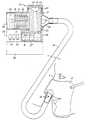
- the apparatus for the treatment of the respiratory tractcomprises an applicator 10 intended to be placed on the face of a patient 11, a generator 12 of humidified hot air and a flexible duct 13 for connect this generator 12 to this applicator 10.
- the generator 12comprises a housing 14 compartmentalized into three main chambers, the first 15 constitutes a water tank, the second 16 contains a porous member 17, and the third 18 contains an electric motor 19 driving a propeller 20 and an electric resistance 21, the assembly constituting a fan generating preheated air.
- the chamber 18is closed at the rear by a grid 22 and communicates at the front with the chamber 16.
- the chamber 16communicates, at its base, with the water tank 15 via the porous member 17 which passes through the chamber 16 right through, and the lower end of which dips into the reservoir 15.
- a seal 23seals between the porous member 17 and the lower wall of the chamber 16, and the upper wall of the reservoir 15.
- the porous member 17preferably has a hollow cylindrical shape, the upper end 24 of which is flared, so as to have a funnel shape.
- the chamber 16is closed by a cover 25, for example screwed onto the side wall of this chamber, which allows the filling of the reservoir.
- the cover 25When the cover 25 is removed, the user can pour water, possibly mixed with a treatment liquid, into the funnel 24.
- This liquidflows through the central bore 26 of the porous member 17 in the reservoir 15.
- the porous member 17comprises at least one slot 27 or a channel 28 passing through its walls, formed in its lower part immersed in the reservoir 15.
- a second seal 29, disposed in the vicinity from the upper end of the porous member 17,completely isolates the part of the device in contact with the reservoir water from the rest of this device.
- An electrical resistance 30surrounds the central part of the porous member 17.
- a conical end piece 31provides the connection between the humidified hot air generator and the flexible duct 13.
- the dimensions of the chamber 16 and of the porous member 17are such that the preheated air, discharged by the fan contained in the chamber 18, flows through a laminar space formed between the peripheral surface of the porous member 17 and the inner side wall of the chamber 16. In this way, the preheated air discharged by the fan scans the surface of the porous member impregnated with water and / or treatment liquid and strongly moistens at this passage.
- a power supply unit 32essentially containing a transformer intended to supply the electric motor 19 at a voltage of, for example, twenty-four volts, is associated with a control unit 33 provided with two indicator lights 34 and a switch 35.
- a temperature probe 36is mounted in the conduit 13 at its end close to the applicator 10 and transmits. at the control block 33, temperature information which allows precise adjustment of preheating and / or air flow, so that the hot and humid air, injected into the nostrils of the patient, has a constant temperature close to 43 ° C, temperature at which the microbes responsible for rhinitis, bronchitis or pharyngitis are destroyed.
- This deviceis particularly effective because it is compact, of simple construction and, therefore, of an affordable cost price, which allows it to be widely distributed.
Landscapes
- Health & Medical Sciences (AREA)
- Engineering & Computer Science (AREA)
- Life Sciences & Earth Sciences (AREA)
- Animal Behavior & Ethology (AREA)
- Anesthesiology (AREA)
- Biomedical Technology (AREA)
- Heart & Thoracic Surgery (AREA)
- Hematology (AREA)
- Veterinary Medicine (AREA)
- Pulmonology (AREA)
- General Health & Medical Sciences (AREA)
- Public Health (AREA)
- Emergency Medicine (AREA)
- Bioinformatics & Cheminformatics (AREA)
- Thermotherapy And Cooling Therapy Devices (AREA)
- External Artificial Organs (AREA)
- Respiratory Apparatuses And Protective Means (AREA)
- Separation Using Semi-Permeable Membranes (AREA)
Abstract
Description
Translated fromFrenchLa présente invention concerne un appareil pour le traitement des voies respiratoires un courant d'air forcé préchauffé et humidifié, comportant un applicateur prévu pour être placé sur le visage d'un patient, un générateur d'air préchauffé humidifié et un conduit souple pour relier ce générateur à cet applicateur, ledit générateur comprenant un boîtier, un ventilateur, au moins une résistance chauffante, un réservoir pour le liquide à évaporer, et des organes de commande dudit générateur.The present invention relates to an apparatus for the treatment of the respiratory tract a stream of forced preheated and humidified air, comprising an applicator intended to be placed on the face of a patient, a generator of preheated humidified air and a flexible duct for connecting this generator to this applicator, said generator comprising a housing, a fan, at least one heating resistor, a reservoir for the liquid to be evaporated, and control members of said generator.
On connaît déjà des appareils de ce type, en particulier un appareil inhalateur décrit par le brevet britannique GB-A-526 678 qui comprend deux chambres superposées dont l'une contient un ventilateur et dont l'autre contient des résistances chauffantes. Un plateau disposé dans la partie supérieure de l'appareil, au-dessus des deux chambres superposées, peut recevoir un. liquide ou un solide destiné à être évaporé.Apparatuses of this type are already known, in particular an inhaler apparatus described by British patent GB-A-526,678 which comprises two superimposed chambers, one of which contains a fan and the other of which contains heating resistors. A tray placed in the upper part of the device, above the two superimposed chambers, can receive one. liquid or solid intended to be evaporated.
Cet appareil ne comporte pas de réservoir d'eau et n'est pas en mesure de produire un courant d'air fortement humidifié ayant une température de sortie déterminée.This device does not have a water tank and is not able to produce a highly humidified air stream having a determined outlet temperature.
On connaît également un autre appareil décrit par la publication française FR-A-2056428 qui concerne un appareil inhalateur pourvu d'un petit réservoir définissant un compartiment annulaire de faible capacité dont une des parois est constituée par un élément cylindrique dans l'épaisseur duquel est incrustée une résistance chauffante.Another device is also known, described by French publication FR-A-2056428, which relates to an inhaler device provided with a small reservoir defining an annular compartment of low capacity, one of the walls of which is constituted by a cylindrical element in the thickness of which is embedded heating resistance.
Cet appareil fonctionne comme un évaporateur dépourvu de soufflerie susceptible de créer un courant d'air humidifié. L'air est aspiré par le patient, longe la paroi extérieure du réservoir réalisé en un matériau poreux, et traverse l'ouverture centrale de l'élément cylindrique chauffant.This device works like an evaporator without a blower capable of creating a humidified air current. The air is sucked in by the patient, runs along the outer wall of the reservoir made of a porous material, and passes through the central opening of the cylindrical heating element.
Cet appareil ne permet pas d'obtenir un courant d'air fortement humidifié, délivré à une température de sortie déterminée.This device does not make it possible to obtain a highly humidified air stream, delivered at a determined outlet temperature.
Afin d'humidifier l'air plus fortement, la publication FR-A-1 048 008 décrit un appareil comportant un organe poreux, constitué par une mèche qui plonge dans un réservoir de liquide et qui est léchée par un courant d'air. Cependant, vu. la surface d'évaporation relativement faible, le débit d'air humidifié est très limité. En outre, sa température dépend directement de celle du moteur.In order to humidify the air more strongly, the publication FR-A-1 048 008 describes an apparatus comprising a porous member, constituted by a wick which plunges into a reservoir of liquid and which is licked by a current of air. However, seen. the relatively small evaporation surface, the humidified air flow is very limited. In addition, its temperature depends directly on that of the engine.
Il existe encore d'autres appareils lourds, encombrants et coûteux, dont l'utilisation est exclusivement réservée aux centres hospitaliers, en raison précisément de leur encombrement et de leur coût. Leur faible diffusion les rend peu efficaces dans la lutte contre les rhinites ou autres affections des voies respiratoires.There are still other heavy, bulky and expensive devices, the use of which is exclusively reserved for hospitals, precisely because of their size and cost. Their low distribution makes them ineffective in the fight against rhinitis or other respiratory diseases.
La présente invention se propose de pallier ces divers inconvénients en réalisant un appareil efficace, de construction simplifiée, ce qui rend son prix acceptable pour le public et qui satisfait. de par ses caractéristiques, exactement les exigences de base devant être remplies pour assurer une lutte efficace contre les maladies susmentionnées.The present invention proposes to overcome these various drawbacks by providing an efficient device, of simplified construction, which makes its price acceptable to the public and which satisfies. by its characteristics, exactly the basic requirements to be fulfilled to ensure an effective fight against the above-mentioned diseases.
Dans ce but, l'appareil selon l'invention est caractérisé en ce que le réservoir pour le liquide à évaporer est étanche et en ce que ledit appareil comporte de plus un organe poreux partiellement plongé dans ce réservoir et léché par le courant d'air et une sonde de température, montée dans le conduit d'air à proximité de l'entrée de l'applicateur et reliée aux organes de commande pour leur transmettre une information de température permettant un réglage de générateur.For this purpose, the apparatus according to the invention is characterized in that the reservoir for the liquid to be evaporated is sealed and in that said apparatus further comprises a porous member partially immersed in this reservoir and licked by the air stream and a temperature probe, mounted in the air duct near the inlet of the applicator and connected to the control members to transmit temperature information to them allowing generator setting.
A l'intérieur du générateur, une chambre est conçue de préférence de telle manière qu'il existe, entre la paroi intérieure de cette chambre et la surface extérieure de l'organe poreux, un espace étroit qui définit un passage forcé du courant d'air préchauffé balayant la surface extérieure de l'organe poreux. Cet espace ou ce couloir est de préférence très étroit de sorte qu'un maximum d'air est amené en contact étroit avec la surface extérieure de l'organe poreux et se charge d'humidité par ce contact.Inside the generator, a chamber is preferably designed so that there exists, between the interior wall of this chamber and the exterior surface of the porous member, a narrow space which defines a forced passage of the current. preheated air sweeping the exterior surface of the porous member. This space or this corridor is preferably very narrow so that a maximum of air is brought into close contact with the external surface of the porous member and is charged with moisture by this contact.
Une résistance chauffante est de préférence enroulée autour de l'organe poreux, cette résistance étant disposée au moins partiellement dans la zone du passage forcé du courant d'air préchauffé. Cette résistance assure l'évaporation du film d'eau à la surface extérieure de l'organe poreux.A heating resistor is preferably wound around the porous member, this resistor being arranged at least partially in the region of the forced passage of the preheated air stream. This resistance ensures the evaporation of the water film on the outer surface of the porous member.
L'organe poreux se compose de préférence d'un corps cylindrique creux, évasé à sa partie supérieure et fendu à sa base. Le boîtier comporte de préférence un couvercle de remplissage, ménagé en regard de l'extrémité supérieure évasée de l'organe poreux. De cette manière, il est aisé de remplir le réservoir en versant de l'eau à l'intérieur du corps cylindrique creux de 'l'organe poreux, à sa partie supérieure évasée qui joue le rôle d'un entonnoir. La fente ménagée à sa base permet l'écoulement de l'eau ou de tout autre liquide de traitement à l'intérieur du réservoir.The porous organ preferably consists of a hollow cylindrical body, flared at its upper part and split at its base. The housing preferably comprises a filling cover, arranged opposite the flared upper end of the porous member. In this way, it is easy to fill the reservoir by pouring water inside the hollow cylindrical body of the porous member, at its flared upper part which acts as a funnel. The slot at its base allows the flow of water or any other treatment liquid inside the tank.
L'appareil comporte également un bloc d'alimentation électrique et de commande, qui est de préférence rapporté au boîtier contenant le réservoir, l'organe poreux et le générateur d'air préchauffé. Le raccordement électrique peut se faire par des fiches de raccordement ou un connecteur, dont une partie est solidaire du boîtier et l'autre partie du bloc d'alimentation.The device also includes an electrical power supply and control unit, which is preferably attached to the housing containing the reservoir, the porous member and the preheated air generator. The electrical connection can be made by plugs or a connector, part of which is secured to the housing and the other part of the power supply.
La présente invention sera mieux comprise en référence à la description d'un exemple de réalisation préféré et du dessin annexé qui représente une vue schématique, partiellement coupée de l'appareil selon l'invention.The present invention will be better understood with reference to the description of a preferred embodiment and the appended drawing which represents a schematic view, partially cut away, of the apparatus according to the invention.
En référence à la figure, l'appareil pour le traitement des voies respiratoires selon l'invention comporte un applicateur 10 prévu pour être placé sur le visage d'un patient 11, un générateur 12 d'air chaud humidifié et un conduit souple 13 pour relier ce générateur 12 à cet applicateur 10. Le générateur 12 comprend un boîtier 14 compartimenté en trois chambres principales, dont la première 15 constitue un réservoir d'eau, la seconde 16 contient un organe poreux 17, et la troisième 18 contient un moteur électrique 19 entraînant une hélice 20 et une résistance électrique 21, l'ensemble constituant un ventilateur générateur d'air préchauffé. La chambre 18 est obturée à l'arrière par une grille 22 et communique à l'avant avec la chambre 16. La chambre 16 communique, à sa base, avec le réservoir d'eau 15 par l'intermédiaire de l'organe poreux 17 qui traverse la chambre 16 de part en part, et dont l'extrémité inférieure plonge dans le réservoir 15. Un joint 23 assure l'étanchéité entre l'organe poreux 17 et la paroi inférieure de la chambre 16, et la paroi supérieure du réservoir 15.Referring to the figure, the apparatus for the treatment of the respiratory tract according to the invention comprises an
L'organe poreux 17 a de préférence une forme cylindrique creuse, dont l'extrémité supérieure 24 est évasée, de manière à présenter une forme d'entonnoir. A son extrémité supérieure, la chambre 16 est obturée par un couvercle 25, par exemple vissé sur la paroi latérale de cette chambre, qui permet le remplissage du réservoir. En effet, lorsque le couvercle 25 est retiré, l'utilisateur peut verser de l'eau éventuellement mélangée à un liquide de traitement dans l'entonnoir 24. Ce liquide s'écoule à travers l'alésage central 26 de l'organe poreux 17 dans le réservoir 15. A cet effet, l'organe poreux 17 comporte au moins une fente 27 ou un canal 28 traversant ses parois, ménagé dans sa partie inférieure plongée dans le réservoir 15. Un second joint d'étanchéité 29, disposé au voisinage de l'extrémité supérieure de l'organe poreux 17, permet d'isoler complètement la partie de l'appareil en contact avec l'eau du réservoir du reste de cet appareil. Une résistance électrique 30 entoure la partie centrale de l'organe poreux 17. Un embout conique 31 assure la liaison entre le générateur d'air chaud humidifié et le conduit souple 13.The
Les dimensions de la chambre 16 et de l'organe poreux 17 sont telles que l'air préchauffé, refoulé par le ventilateur contenu dans la chambre 18, s'écoule à travers un espace laminaire ménagé entre la surface périphérique de l'organe poreux 17 et la paroi latérale intérieure de la chambre 16. De cette manière, l'air préchauffé refoulé par le ventilateur balaye la surface de l'organe poreux imprégné d'eau et/ou de liquide de traitement et s'humidifie fortement à ce passage.The dimensions of the
Un bloc d'alimentation 32, contenant essentiellement un transformateur destiné à alimenter le moteur électrique 19 sous une tension de par exemple vingt-quatre volts, est associé à un bloc de commande 33 pourvu de deux voyants lumineux 34 et d'un interrupteur 35. Une sonde de température 36 est montée dans le conduit 13 à son extrémité voisine de l'applicateur 10 et transmet. au bloc de commande 33, une information de température qui permet un réglage précis de préchauffage et/ou du débit de l'air, pour que l'air chaud et humide, injecté dans les narines du patient, ait une température constante voisine de 43 °C, température à laquelle les microbes responsables de la rhinite, de la bronchite ou de la pharyngite sont détruits.A
Cet appareil est particulièrement efficace parce qu'il est compact, de construction simple et, par conséquent, d'un prix de revient abordable, ce qui lui permet d'être diffusé de façon très large.This device is particularly effective because it is compact, of simple construction and, therefore, of an affordable cost price, which allows it to be widely distributed.
Claims (5)
Priority Applications (1)
| Application Number | Priority Date | Filing Date | Title |
|---|---|---|---|
| AT84810220TATE31482T1 (en) | 1983-05-09 | 1984-05-08 | DEVICE FOR TREATMENT OF THE RESPIRATORY TRACT. |
Applications Claiming Priority (2)
| Application Number | Priority Date | Filing Date | Title |
|---|---|---|---|
| FR8307846 | 1983-05-09 | ||
| FR8307846AFR2545723B1 (en) | 1983-05-09 | 1983-05-09 | APPARATUS FOR THE TREATMENT OF THE RESPIRATORY TRACT |
Publications (2)
| Publication Number | Publication Date |
|---|---|
| EP0125210A1 EP0125210A1 (en) | 1984-11-14 |
| EP0125210B1true EP0125210B1 (en) | 1987-12-23 |
Family
ID=9288776
Family Applications (1)
| Application Number | Title | Priority Date | Filing Date |
|---|---|---|---|
| EP84810220AExpiredEP0125210B1 (en) | 1983-05-09 | 1984-05-08 | Apparatus for treating the respiratory passages |
Country Status (4)
| Country | Link |
|---|---|
| EP (1) | EP0125210B1 (en) |
| AT (1) | ATE31482T1 (en) |
| DE (1) | DE3468175D1 (en) |
| FR (1) | FR2545723B1 (en) |
Cited By (1)
| Publication number | Priority date | Publication date | Assignee | Title |
|---|---|---|---|---|
| EP3061359B1 (en) | 2006-05-16 | 2018-10-03 | Fontem Holdings 1 B.V. | Aerosol electronic cigarette |
Families Citing this family (23)
| Publication number | Priority date | Publication date | Assignee | Title |
|---|---|---|---|---|
| US4523589A (en)* | 1983-06-29 | 1985-06-18 | Krauser Robert S | Method and apparatus for treating ailments |
| US4676237A (en)* | 1985-01-29 | 1987-06-30 | Boutade Worldwide Investments Nv | Inhaler device |
| GB2192136B (en)* | 1986-07-04 | 1991-01-02 | Virotherm Lab Ltd | Medical breathing apparatus |
| US4805614A (en)* | 1987-07-01 | 1989-02-21 | Yahav Limited | Rhinitis relief device |
| GB8809039D0 (en)* | 1988-04-16 | 1988-05-18 | Virotherm Lab | Medical breathing apparatus |
| US5209227A (en)* | 1990-09-25 | 1993-05-11 | Richard Deutsch | Thermoelectric therapy device and moisturizing device therefor |
| DE4116512A1 (en)* | 1991-05-21 | 1992-11-26 | Draegerwerk Ag | NARCOSIS EVAPORATOR WITH FLOWABLE EVAPORATION ELEMENTS |
| RU2193899C2 (en)* | 1999-09-03 | 2002-12-10 | Илья Васильевич Крячко | Mask for carrying out treatment and prophylaxis |
| GB9929486D0 (en)* | 1999-12-15 | 2000-02-09 | Glaxo Group Ltd | Inhalation delivery apparatus and method |
| US8100126B2 (en) | 2000-06-14 | 2012-01-24 | Mcauley Alastair Edwin | Breathing assistance apparatus |
| EP1289590B1 (en) | 2000-06-14 | 2017-08-09 | Fisher & Paykel Healthcare Limited | Breathing assistance apparatus |
| DE20016753U1 (en)* | 2000-09-28 | 2000-12-28 | Iffert, Hans Jürgen, 83250 Marquartstein | Air conditioner |
| RU2195966C2 (en)* | 2000-10-13 | 2003-01-10 | Тель Леонид Зигмонтович | Device for creating physiological hypercapnia in human patient |
| EP1302212A3 (en)* | 2001-10-10 | 2004-01-21 | Fisher & Paykel Healthcare Limited | Forehead support for a facial mask |
| RU2201769C1 (en)* | 2002-03-14 | 2003-04-10 | Чижов Алексей Ярославович | Apparatus for assisting breathing |
| RU2219976C1 (en)* | 2002-07-04 | 2003-12-27 | Федеральное государственное унитарное предприятие Научно-производственное предприятие "Полет" | Device for treatment by aeroions |
| DE10312881B3 (en)* | 2003-03-22 | 2004-05-06 | Drägerwerk AG | Respiration hose for medical respiration apparatus incorporating signal line for signal transmission between sensor device and respiration apparatus at its opposite ends |
| US6961516B2 (en) | 2003-03-31 | 2005-11-01 | Toshiba Ceramics Co., Ltd. | Steam generator and mixer using the same |
| RU2336907C2 (en)* | 2006-02-06 | 2008-10-27 | Сергей Леонидович Устьянцев | Individual ustjantsev-velichkovsky respiratory device |
| WO2010056146A1 (en)* | 2008-11-14 | 2010-05-20 | Suprun Anton Evgenyevich | Inhaler |
| EP2822627A4 (en)* | 2012-03-06 | 2015-10-21 | Mondiale Technologies Ltd | Sterilization and humidification apparatus and incubator |
| EP4010055A4 (en)* | 2019-08-05 | 2023-08-16 | Fisher & Paykel Healthcare Limited | Fast acting humidifier |
| GB2579011A (en)* | 2020-04-02 | 2020-06-03 | The Centre For Maritime & Industrial Safety Tech Limited | A breathing device |
Family Cites Families (4)
| Publication number | Priority date | Publication date | Assignee | Title |
|---|---|---|---|---|
| GB526678A (en)* | 1939-03-21 | 1940-09-24 | Henry William Headland | Improvements in or relating to inhalers and chemical vaporizers |
| US2479967A (en)* | 1946-11-15 | 1949-08-23 | Frank M Risch | Chlorine inhalator |
| BE505525A (en)* | 1950-12-12 | |||
| CH507715A (en)* | 1969-07-01 | 1971-05-31 | Hirtz Hans | Device for treating the respiratory tract with warm air |
- 1983
- 1983-05-09FRFR8307846Apatent/FR2545723B1/ennot_activeExpired
- 1984
- 1984-05-08DEDE8484810220Tpatent/DE3468175D1/ennot_activeExpired
- 1984-05-08EPEP84810220Apatent/EP0125210B1/ennot_activeExpired
- 1984-05-08ATAT84810220Tpatent/ATE31482T1/enactive
Cited By (5)
| Publication number | Priority date | Publication date | Assignee | Title |
|---|---|---|---|---|
| EP3061359B1 (en) | 2006-05-16 | 2018-10-03 | Fontem Holdings 1 B.V. | Aerosol electronic cigarette |
| EP2789250B1 (en) | 2006-05-16 | 2018-12-26 | Fontem Holdings 1 B.V. | An aerosol electronic cigarette |
| US10893705B2 (en) | 2006-05-16 | 2021-01-19 | Fontem Holdings 1 B.V. | Electronic cigarette |
| US11083222B2 (en) | 2006-05-16 | 2021-08-10 | Fontem Holdings 1 B.V. | Electronic cigarette having a liquid storage component and a shared central longtiduinal axis among stacked components of a housing, a hollow porous component and a heating coil |
| US12150478B2 (en) | 2006-05-16 | 2024-11-26 | Fontem Ventures B.V. | Electronic cigarette |
Also Published As
| Publication number | Publication date |
|---|---|
| ATE31482T1 (en) | 1988-01-15 |
| EP0125210A1 (en) | 1984-11-14 |
| DE3468175D1 (en) | 1988-02-04 |
| FR2545723B1 (en) | 1986-08-14 |
| FR2545723A1 (en) | 1984-11-16 |
Similar Documents
| Publication | Publication Date | Title |
|---|---|---|
| EP0125210B1 (en) | Apparatus for treating the respiratory passages | |
| EP0169151B1 (en) | Portable device for inhalation of warm, humidified air | |
| CA2859994A1 (en) | Liquid tank for medical gas humidifier | |
| KR100868012B1 (en) | Skin care appliance | |
| US20100212679A1 (en) | Electric heating for hookah | |
| EP0780083B1 (en) | Electric apparatus for steam cleaning of smooth surfaces such as window-panes | |
| EP0672425A1 (en) | Dynamic dispenser for a substance such as a perfume | |
| CN111317180A (en) | Atomizer and electronic cigarette | |
| LU84360A1 (en) | MEDICAL APPARATUS FOR SENDING HOT AND WET AIR TO THE NARINES | |
| FR2725373A1 (en) | HUMIDIFIER CHAMBER | |
| CN207707306U (en) | A kind of atomizer and electronic cigarette | |
| FR2730640A1 (en) | SYSTEM FOR HUMIDIFYING A GAS BLOWED TO A PATIENT | |
| FR3039039A1 (en) | DEVICE FOR INHALING AN E-LIQUID WITH LOW ASPIRATION RESISTANCE | |
| CN112772994A (en) | Nebulizer and aerosol generating device | |
| US5761378A (en) | Hair curler steamer with PTC heater and thermally isolated cold and hot water reservoirs | |
| US20230100436A1 (en) | Laser smoking apparatus | |
| US4155001A (en) | Electrode-type vaporizer | |
| FR2641455A1 (en) | Air-conditioning device, particularly for a bed or the like | |
| FR3081713A1 (en) | ASSEMBLY OF A MEDICAL FAN AND A GAS HUMIDIFIER WITH PROTECTION AGAINST UPWATER | |
| FR2677437A1 (en) | Portable apparatus for blowing humidified (moistened) and cooled air | |
| EP4072637B1 (en) | Humidification device for a positive airway pressure breathing apparatus | |
| FR2570280A1 (en) | INHALER APPARATUS FOR THE HEALING OF RUMS | |
| FR3008319A3 (en) | HUMIDIFIER FOR RESPIRATORY ASSISTANCE APPARATUS | |
| FR2576673A1 (en) | ELECTRIC RESISTANCE HEATING CONVECTOR HAVING AIR HUMIDIFYING MEANS | |
| KR20210104400A (en) | Aerosol inhaler and capsule for the aerosol inhaler |
Legal Events
| Date | Code | Title | Description |
|---|---|---|---|
| PUAI | Public reference made under article 153(3) epc to a published international application that has entered the european phase | Free format text:ORIGINAL CODE: 0009012 | |
| AK | Designated contracting states | Designated state(s):AT BE CH DE FR GB IT LI LU NL SE | |
| 17P | Request for examination filed | Effective date:19841103 | |
| GRAA | (expected) grant | Free format text:ORIGINAL CODE: 0009210 | |
| AK | Designated contracting states | Kind code of ref document:B1 Designated state(s):AT BE CH DE FR GB IT LI LU NL SE | |
| PG25 | Lapsed in a contracting state [announced via postgrant information from national office to epo] | Ref country code:NL Effective date:19871223 Ref country code:IT Free format text:LAPSE BECAUSE OF FAILURE TO SUBMIT A TRANSLATION OF THE DESCRIPTION OR TO PAY THE FEE WITHIN THE PRESCRIBED TIME-LIMIT;WARNING: LAPSES OF ITALIAN PATENTS WITH EFFECTIVE DATE BEFORE 2007 MAY HAVE OCCURRED AT ANY TIME BEFORE 2007. THE CORRECT EFFECTIVE DATE MAY BE DIFFERENT FROM THE ONE RECORDED. Effective date:19871223 Ref country code:AT Effective date:19871223 | |
| REF | Corresponds to: | Ref document number:31482 Country of ref document:AT Date of ref document:19880115 Kind code of ref document:T | |
| PG25 | Lapsed in a contracting state [announced via postgrant information from national office to epo] | Ref country code:SE Effective date:19871231 | |
| REF | Corresponds to: | Ref document number:3468175 Country of ref document:DE Date of ref document:19880204 | |
| NLV1 | Nl: lapsed or annulled due to failure to fulfill the requirements of art. 29p and 29m of the patents act | ||
| PG25 | Lapsed in a contracting state [announced via postgrant information from national office to epo] | Ref country code:LU Free format text:LAPSE BECAUSE OF NON-PAYMENT OF DUE FEES Effective date:19880531 Ref country code:LI Effective date:19880531 Ref country code:CH Effective date:19880531 | |
| GBV | Gb: ep patent (uk) treated as always having been void in accordance with gb section 77(7)/1977 [no translation filed] | ||
| PLBE | No opposition filed within time limit | Free format text:ORIGINAL CODE: 0009261 | |
| STAA | Information on the status of an ep patent application or granted ep patent | Free format text:STATUS: NO OPPOSITION FILED WITHIN TIME LIMIT | |
| PG25 | Lapsed in a contracting state [announced via postgrant information from national office to epo] | Ref country code:GB Free format text:LAPSE BECAUSE OF NON-PAYMENT OF DUE FEES Effective date:19881122 | |
| BERE | Be: lapsed | Owner name:S.A. PIERRE FABRE Effective date:19880531 | |
| 26N | No opposition filed | ||
| REG | Reference to a national code | Ref country code:CH Ref legal event code:PL | |
| PG25 | Lapsed in a contracting state [announced via postgrant information from national office to epo] | Ref country code:DE Effective date:19890201 | |
| PG25 | Lapsed in a contracting state [announced via postgrant information from national office to epo] | Ref country code:BE Effective date:19890531 | |
| PGFP | Annual fee paid to national office [announced via postgrant information from national office to epo] | Ref country code:FR Payment date:19970529 Year of fee payment:14 | |
| PG25 | Lapsed in a contracting state [announced via postgrant information from national office to epo] | Ref country code:FR Free format text:LAPSE BECAUSE OF NON-PAYMENT OF DUE FEES Effective date:19980531 | |
| REG | Reference to a national code | Ref country code:FR Ref legal event code:ST |