EP0124372B1 - Three-wheeled motor vehicle - Google Patents
Three-wheeled motor vehicleDownload PDFInfo
- Publication number
- EP0124372B1 EP0124372B1EP84302871AEP84302871AEP0124372B1EP 0124372 B1EP0124372 B1EP 0124372B1EP 84302871 AEP84302871 AEP 84302871AEP 84302871 AEP84302871 AEP 84302871AEP 0124372 B1EP0124372 B1EP 0124372B1
- Authority
- EP
- European Patent Office
- Prior art keywords
- vehicle body
- motor vehicle
- wheeled motor
- engine
- compartment
- Prior art date
- Legal status (The legal status is an assumption and is not a legal conclusion. Google has not performed a legal analysis and makes no representation as to the accuracy of the status listed.)
- Expired
Links
- 239000002828fuel tankSubstances0.000claimsdescription5
- 230000007704transitionEffects0.000claimsdescription2
- 238000010276constructionMethods0.000description3
- 239000000725suspensionSubstances0.000description3
- 230000000052comparative effectEffects0.000description2
- 238000013016dampingMethods0.000description2
- 239000000446fuelSubstances0.000description2
- 230000005484gravityEffects0.000description2
- 239000006096absorbing agentSubstances0.000description1
- 238000005452bendingMethods0.000description1
- 238000002156mixingMethods0.000description1
- 230000035939shockEffects0.000description1
- 238000009423ventilationMethods0.000description1
Images


Classifications
- B—PERFORMING OPERATIONS; TRANSPORTING
- B62—LAND VEHICLES FOR TRAVELLING OTHERWISE THAN ON RAILS
- B62D—MOTOR VEHICLES; TRAILERS
- B62D61/00—Motor vehicles or trailers, characterised by the arrangement or number of wheels, not otherwise provided for, e.g. four wheels in diamond pattern
- B62D61/06—Motor vehicles or trailers, characterised by the arrangement or number of wheels, not otherwise provided for, e.g. four wheels in diamond pattern with only three wheels
- B62D61/065—Motor vehicles or trailers, characterised by the arrangement or number of wheels, not otherwise provided for, e.g. four wheels in diamond pattern with only three wheels with single rear wheel
- B—PERFORMING OPERATIONS; TRANSPORTING
- B62—LAND VEHICLES FOR TRAVELLING OTHERWISE THAN ON RAILS
- B62D—MOTOR VEHICLES; TRAILERS
- B62D31/00—Superstructures for passenger vehicles
- B62D31/003—Superstructures for passenger vehicles compact cars, e.g. city cars
Definitions
- the present inventionrelates to a three- wheeled motor vehicle, and more particularly to a body configuration for such a motor vehicle.
- Autombiles that can be driven easily by anybodyshould not be able to fall over of their own accord, or stated otherwise should be other than one-wheeled or two-wheeled vehicles that require a certain level of driving skill on the part of the driver in order to be manoeuvered well.
- the inventorshave therefore selected three wheels for a motor vehicle to be constructed, which is the least number for stably supporting the vehicle on the ground.
- the vehicleshould be light in weight and have a small aerodynamic drag. Good mileage therefore hinges largely on the design of the shape of the vehicle body.
- the inventorshave made efforts to design a vehicle body of a configuration which has a small forward projection area and a small cross-sectional change, while providing a sufficient vehicle compartment space, and which is as streamlined as possible.
- Thisis three-wheeled motor vehicle having two front wheels, a single rear wheel, an engine disposed between said front wheels, a driver's compartment, and a vehicle body including a front portion covering said engine and said front wheels and a rear portion disposed behind said front portion and covering said compartment and said rear wheel, said front portion having a relatively wide and flat shape and said rear portion being narrower than said front portion and being progressively higher in the rearward direction over a substantial proportion of said rear portion.
- the vehicle bodyalso includes lateral wing portions on each side which extend longitudinally rearwardly from behind the front wheels and taper into said body rear portion, whereby the vehicle body has a substantially constant transverse cross-sectional area throughout a substantial proportion ofboth said front and, rear portions thereof, including the transition between said front and rear portions.
- FIGS. 1 through 4show a first embodiment of a three-wheeled motor vehicle according to the present invention.
- the three-wheeled motor vehicleincludes a vehicle body 1 having a front engine space 10 and a rear driver's compartment 20. Two front wheels 2 and a single rear wheel 3 are rotatably mounted on the vehicle body 1.
- the engine space 10is covered with an engine hood 1a disposed above an engine arranged in the engine space 10 transversely and centrally of the vehicle body 1, and a pair of front fenders 1c extending contiguously from the engine hood 1 a in opposite directions away from each other.
- the engine space 10has therefore a wide, flat configuration.
- the driver's compartment 20is positioned behind the engine space 10 in contiguous relation thereto and is of a relatively small width substantially equal to that of the engine hood 1a.
- the driver's compartment 20includes a roof 1b doubling as a windshield and becoming progressively higher toward a highest roof portion 1d d adjacent the rear end portion of the vehicle body 1.
- the vehicle body 1is substantially triangular in shape when viewed in side elevation, to provide a compartment space large enough for the driver, seated on a seat 4 therein, to sit and move therein in order to manoeuvre the motor vehicle.
- the driver's compartment 20,which is itself narrow, includes front lateral wings 1e projecting away from each other and having surfaces blending into the surfaces of the front fenders 1c.
- the front fenders 1c and the front lateral wings 1eproject laterally to a progressively lesser extent in the rearward direction of the vehicle body 1, and have contiguous side surfaces 1g, 1h, respectively, which taper progressively toward each other in the rearward direction of the vehicle body 1.
- the front portion of the vehicle body 1has a substantially triangular shape when viewed in plan, to guide air streams to flow smoothly along the tapered side surfaces 1g, 1h of the front fenders 1c and the lateral wings 1e toward the rear end of the vehicle body 1.
- a reflector plate 5is attached to the tapered side surface 1g of each front fender 1c to allow light reflected by the reflector plate 5 to be seen by other drivers or observers in a wide arc extending from a position behind the motor vehicle to a position laterally of the motor vehicle.
- the transverse cross-sectional areas of the vehicle body 1remain substantially the same along a longitudinal axis thereof from the wide and flat front end portion to the narrow and highest portion.
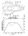
- FIG. 5is a graph showing various transverse cross-sectional areas of the vehicle body 1 of the vehicle shown in FIGS. 1 through 4, along the longitudinal axis thereof, with the wheel base being 2,200 mm, the tread between the front wheels 2 being 1,300 mm, and the largest vehicle height H being 1,350 mm.
- the graphhas a horizontal axis representing the distance x from the axial center of the front wheel 2 in the direction of the arrow of FIG. 2, which is regarded as positive.
- the dotted-line curve in FIG. 5is indicative of the varying transverse cross-sectional areas of a vehicle body having no lateral wings behind its front fenders.
- FIGS. 9 and 10illustrate a vehicle body 51 of a three-wheeled motor vehicle constructed according to the present invention for a wind-tunnel experiment.
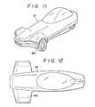
- FIGS. 11 and 12show a vehicle body 61 of a three-wheeled motor vehicle according to a comparative example, as constructed for a wind-tunnel experiment for comparison with the vehicle body 51.
- the vehicle body 61has front fenders 61c but no lateral wings behind the front fenders, with the result that the overall vehicle body 61 has a substantially T-shaped configuration when viewed in plan.
- a wind-tunnel experimentwas conducted using the vehicle bodies 51 and 61, and the result of the wind-tunnel experiment indicated that the coefficient of air resistance of the T-shaped vehicle body 61 was 0.386 while that of the vehicle body 51 according to the present invention was 0.313.
- the smaller coefficient of air resistanceresults from the fact that an air stream flowing rearward from the upper and side surfaces of the front fenders 1c is guided along the lateral wings 1e toward rear side surfaces of the vehicle body 1 without burbling from the lateral wings 1e, thus reducing any resistance tending to cause the air current to burble from the sides of the vehicle body.
- the vehicle body 1has a forward projection area of 10.92 x 10 5 mm 2 , which is the sum of the transverse cross-sectional area of the front portion of the vehicle body 1 and the transverse cross-sectional area of the upper half of the vehicle body rear portion.
- the transverse cross- sectional area of any portion of the vehicleis much smaller than the forward projection area thereof. This, together with the fact that the transverse crosssectional area of the vehicle body is rendered substantially constant by the lateral wings 1e, results in the small coefficient of air resistance.
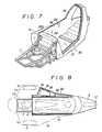
- a driver's compartment 20may comprise a body 30 of box- shaped monocoque structure having a side sill 31 on one side, a relatively high side member 32, a front toe board 33, and a rear pillar 34 extending between the side sill 30 and the side member 32.
- a gullwing door 6is hinged to an upper edge of the side member 32 so that the driver's compartment 20 is openable on one side thereof.
- the lateral wings 1eare formed by laterally bulging outer panels 32a, 6a of the side member 32 and the door 6, respectively.
- a fuel tank 15is mounted by mounts 14 in a large interior space in the lateral wing 1e on the side member 32.
- the fuel tank 15is housed in the side member 32 of the monocoque structure 30 for effective space utilization therein.
- three-wheeled motor vehicles having two front wheelshave better cornering characteristics and a comparatively stable vehicle body, as the center of gravity of the vehicle is positioned closer to the front end of the vehicle.
- the center of gravity of the motor vehicleis displaced further forward, thereby to improve cornering characteristics. Designated in FIGS.
- FIG. 7 and 8by the reference numeral 7 is a mounting frame for an engine E, connected to the front end of the monocoque structure 30 and extending forwardly thereof.
- Designated in FIG. 4 by the reference numeral 8is an air ventilation hole defined in a rear spoiler 1f on the rear end of the vehicle body 1 and communicating with the driver's compartment.
- the support frame 21has a lateral end fixed to the side member 32.
- the toeboard 33, the side member 32, and the support frame 21 attached therebetweenjointly constitute a truss for supporting the steering column 24 on the support frame 21 with a high degree of rigidity.
- FIG. 14illustrates a suspension for the rear wheel 3.
- the rear wheel 3is rotatably supported by a rear fork 16 having a pair of laterally spaced fork members 16a pivotally mounted on a lower rear end 34a of the rear pillar 34 of the monocoque structure 30.
- the suspensionincludes a damping member or shock absorber 17 having one end connected to one of the fork members 16a and an opposite end to a rear end of the side member 32.
- the relatively high side member 32 at the right-hand side of the structure 30has a large section modulus against a vertical bending moment, so that the weight of the vehicle body 1 can reliably be borne by the monocoque structure 30.
- the side member 32may be of a hollow shape which is light in weight. Accordingly, it is not necessary to reinforce the monocoque structure 30 with separate stiffening members, and hence the vehicle body 1 is light in weight and of a simple structure.
- FIGS. 15 and 16illustrate a three-wheeled motor vehicle according to another embodiment of the present invention, which has a laterally openable door.
- the motor vehiclehas a vehicle body 101 including lateral slanted sides 108, 109 progressively converging toward the central axis of the vehicle body 101 from a wider front portion to a narrower rear portion thereof.
- a laterally openable door 110is hinged to one of the slanted sides, namely the left-hand side 108 in the illustrated embodiment.
- the doorhas a window 111-1, and the vehicle body 101 also has a front window 111-2 and a right-hand window 111-3.
- These windows 111-1, 111-2, 111-3jointly constitute a continuous window surrounding a driver's compartment 120 and extending from the front of the lateral sides of the driver's compartment 120 when the door 110 is closed, as shown in FIG. 16.
- a single door 110is provided on the left-hand side of the vehicle body 101, two separate doors may be hinged to the opposite sides of the vehicle body 101.
- the door 110has a hinge 112 at a front edge thereof, at a wider portion of the vehicle body, and is openable away from a narrower vehicle body portion.
- the door 110when the door 110 is opened to the lateral extent which does not extend beyond a line L- L passing through the outermost edge of the front fender parallel to the longitudinal axis of the vehicle body 101, the door 110 provides a large opening 113, opening rearward, to allow the driver easily to get into or out of the driver's compartment 120.
- FIG. 16also shows an imaginary position 110' that would be assumed by an opened door hinged at its rear edge to the narrower vehicle body portion.
Landscapes
- Engineering & Computer Science (AREA)
- Chemical & Material Sciences (AREA)
- Combustion & Propulsion (AREA)
- Transportation (AREA)
- Mechanical Engineering (AREA)
- Body Structure For Vehicles (AREA)
- Arrangement Or Mounting Of Propulsion Units For Vehicles (AREA)
- Automatic Cycles, And Cycles In General (AREA)
Description
- The present invention relates to a three- wheeled motor vehicle, and more particularly to a body configuration for such a motor vehicle. There has been a strong demand in reent years for automobiles which can be driven easily by anybody and provide good fuel economy.
- The present invention has been made basically with a view to meeting the above demand. The fundamental concepts which the inventors have had in mind in arriving at the invention are as follows:
- Autombiles that can be driven easily by anybody should not be able to fall over of their own accord, or stated otherwise should be other than one-wheeled or two-wheeled vehicles that require a certain level of driving skill on the part of the driver in order to be manoeuvered well. The inventors have therefore selected three wheels for a motor vehicle to be constructed, which is the least number for stably supporting the vehicle on the ground. For better fuel economy, the vehicle should be light in weight and have a small aerodynamic drag. Good mileage therefore hinges largely on the design of the shape of the vehicle body. The inventors have made efforts to design a vehicle body of a configuration which has a small forward projection area and a small cross-sectional change, while providing a sufficient vehicle compartment space, and which is as streamlined as possible.
- Based on the foregoing fundamental concept, it is an object of the present invention to provide a three-wheeled motor vehicle having a small aerodynamic drag.
- The magazine "Stern", No. 43 of 1979, discloses a vehicle identified therein as the "Deluxe Freeway II". This is three-wheeled motor vehicle having two front wheels, a single rear wheel, an engine disposed between said front wheels, a driver's compartment, and a vehicle body including a front portion covering said engine and said front wheels and a rear portion disposed behind said front portion and covering said compartment and said rear wheel, said front portion having a relatively wide and flat shape and said rear portion being narrower than said front portion and being progressively higher in the rearward direction over a substantial proportion of said rear portion.
- According to the present invention there is provided such a three-wheeled motor vehicle, characterised in that the said vehicle body also includes lateral wing portions on each side which extend longitudinally rearwardly from behind the front wheels and taper into said body rear portion, whereby the vehicle body has a substantially constant transverse cross-sectional area throughout a substantial proportion ofboth said front and, rear portions thereof, including the transition between said front and rear portions.
- Some embodiments of the invention will now be described by way of example and with reference to the accompanying drawings, in which:-
- FIG. 1 is a perspective view of a three-wheeled motor vehicle according to the present invention;
- FIG. 2 is a side elevational view of the three- wheeled motor vehicle shown in FIG. 1;
- FIG. 3 is a plan view of the three-wheeled motorvehicle of FIG. 1;
- FIG. 4 is a rear elevational view of the three- wheeled motor vehicle of FIG. 1;
- FIG. 5 is a graph of various transverse cross- sectional areas of the three-wheeled motor vehicle along a longitudinal axis thereof;
- FIG. 6 is a cross-sectional view taken along line VI - VI of FIG. 2;
- FIG. 7 is a perspective view of a monocoque construction having a driver's compartment;
- FIG. 8 is a schematic plan view, with parts in cross section, of a vehicle body with the monocoque construction of FIG. 7 assembled therein;
- FIG. 9 is a perspective view of a three-wheeled motor vehicle according to the present invention, as constructed for a wind-tunnel experiment;
- FIG. 10 is a plan view of the three-wheeled motor vehicle shown in FIG. 9;
- FIG. 11 is a perspective view of a threewheeled motor vehicle of a comparative example not according to the invention, as constructed for a wind-tunnel experiment;
- FIG. 12 is a plan view of the three-wheeled motor vehicle of FIG. 11;
- FIG. 13 is a perspective view of a steering column support construction in a front portion of a driver's compartment in a vehicle according to the present invention;
- FIG. 14 is a perspective view of the vehicle, showing a rear wheel suspension;
- FIG. 15 is a perspective view of a modified three-wheeled motor vehicle of the present invention, having a laterally openable door; and
- FIG. 16 is a plan view of the three-wheeled motor vehicle illustrated in FIG. 15.
- FIGS. 1 through 4 show a first embodiment of a three-wheeled motor vehicle according to the present invention. The three-wheeled motor vehicle includes a
vehicle body 1 having afront engine space 10 and a rear driver'scompartment 20. Twofront wheels 2 and a singlerear wheel 3 are rotatably mounted on thevehicle body 1. Theengine space 10 is covered with anengine hood 1a disposed above an engine arranged in theengine space 10 transversely and centrally of thevehicle body 1, and a pair offront fenders 1c extending contiguously from theengine hood 1 a in opposite directions away from each other. Theengine space 10 has therefore a wide, flat configuration. The driver'scompartment 20 is positioned behind theengine space 10 in contiguous relation thereto and is of a relatively small width substantially equal to that of theengine hood 1a. The driver'scompartment 20 includes aroof 1b doubling as a windshield and becoming progressively higher toward ahighest roof portion 1d d adjacent the rear end portion of thevehicle body 1. Thus, as shown in FIG. 2, thevehicle body 1 is substantially triangular in shape when viewed in side elevation, to provide a compartment space large enough for the driver, seated on aseat 4 therein, to sit and move therein in order to manoeuvre the motor vehicle. - The driver's
compartment 20, which is itself narrow, includes frontlateral wings 1e projecting away from each other and having surfaces blending into the surfaces of thefront fenders 1c. Thefront fenders 1c and the frontlateral wings 1e project laterally to a progressively lesser extent in the rearward direction of thevehicle body 1, and have contiguous side surfaces 1g, 1h, respectively, which taper progressively toward each other in the rearward direction of thevehicle body 1. Accordingly, as shown in FIG. 3, the front portion of thevehicle body 1 has a substantially triangular shape when viewed in plan, to guide air streams to flow smoothly along the tapered side surfaces 1g, 1h of thefront fenders 1c and thelateral wings 1e toward the rear end of thevehicle body 1. Areflector plate 5 is attached to the tapered side surface 1g of eachfront fender 1c to allow light reflected by thereflector plate 5 to be seen by other drivers or observers in a wide arc extending from a position behind the motor vehicle to a position laterally of the motor vehicle. - With the
engine space 10 and the driver'scompartment 20 thus shaped, the transverse cross-sectional areas of thevehicle body 1 remain substantially the same along a longitudinal axis thereof from the wide and flat front end portion to the narrow and highest portion. - FIG. 5 is a graph showing various transverse cross-sectional areas of the
vehicle body 1 of the vehicle shown in FIGS. 1 through 4, along the longitudinal axis thereof, with the wheel base being 2,200 mm, the tread between thefront wheels 2 being 1,300 mm, and the largest vehicle height H being 1,350 mm. The graph has a horizontal axis representing the distance x from the axial center of thefront wheel 2 in the direction of the arrow of FIG. 2, which is regarded as positive. The dotted-line curve in FIG. 5 is indicative of the varying transverse cross-sectional areas of a vehicle body having no lateral wings behind its front fenders. - FIGS. 9 and 10 illustrate a
vehicle body 51 of a three-wheeled motor vehicle constructed according to the present invention for a wind-tunnel experiment. FIGS. 11 and 12 show avehicle body 61 of a three-wheeled motor vehicle according to a comparative example, as constructed for a wind-tunnel experiment for comparison with thevehicle body 51. Thevehicle body 61 hasfront fenders 61c but no lateral wings behind the front fenders, with the result that theoverall vehicle body 61 has a substantially T-shaped configuration when viewed in plan. A wind-tunnel experiment was conducted using thevehicle bodies shaped vehicle body 61 was 0.386 while that of thevehicle body 51 according to the present invention was 0.313. - The smaller coefficient of air resistance results from the fact that an air stream flowing rearward from the upper and side surfaces of the
front fenders 1c is guided along thelateral wings 1e toward rear side surfaces of thevehicle body 1 without burbling from thelateral wings 1e, thus reducing any resistance tending to cause the air current to burble from the sides of the vehicle body. - The
vehicle body 1 has a forward projection area of 10.92 x 105 mm2, which is the sum of the transverse cross-sectional area of the front portion of thevehicle body 1 and the transverse cross-sectional area of the upper half of the vehicle body rear portion. The transverse cross- sectional area of any portion of the vehicle is much smaller than the forward projection area thereof. This, together with the fact that the transverse crosssectional area of the vehicle body is rendered substantially constant by thelateral wings 1e, results in the small coefficient of air resistance. - As illustrated in FIGS. 6 and 7, a driver's
compartment 20 may comprise abody 30 of box- shaped monocoque structure having aside sill 31 on one side, a relativelyhigh side member 32, afront toe board 33, and arear pillar 34 extending between theside sill 30 and theside member 32. Agullwing door 6 is hinged to an upper edge of theside member 32 so that the driver'scompartment 20 is openable on one side thereof. Thelateral wings 1e are formed by laterally bulgingouter panels side member 32 and thedoor 6, respectively. - As shown in FIG. 8, a
fuel tank 15 is mounted bymounts 14 in a large interior space in thelateral wing 1e on theside member 32. Thus, thefuel tank 15 is housed in theside member 32 of themonocoque structure 30 for effective space utilization therein. Generally, three-wheeled motor vehicles having two front wheels have better cornering characteristics and a comparatively stable vehicle body, as the center of gravity of the vehicle is positioned closer to the front end of the vehicle. With thefuel tank 15 disposed in a front portion of theside member 32, rather than below the rear floor portion of the vehicle body as in a conventional motor vehicle, the center of gravity of the motor vehicle is displaced further forward, thereby to improve cornering characteristics. Designated in FIGS. 7 and 8 by thereference numeral 7 is a mounting frame for an engine E, connected to the front end of themonocoque structure 30 and extending forwardly thereof. Designated in FIG. 4 by thereference numeral 8 is an air ventilation hole defined in a rear spoiler 1f on the rear end of thevehicle body 1 and communicating with the driver's compartment. - As seen in FIG. 13, to the
toe board 33 at the front end of themonocoque structure 30 is attached asupport frame 21 for aninstrument panel 22 on which various instruments are provided. Asteering column 24, through which a steering shaft connected to asteering wheel 23 extends, is supported by abracket 25 on thesupport frame 21. Thesupport frame 21 has a lateral end fixed to theside member 32. Thetoeboard 33, theside member 32, and thesupport frame 21 attached therebetween jointly constitute a truss for supporting thesteering column 24 on thesupport frame 21 with a high degree of rigidity. - FIG. 14 illustrates a suspension for the
rear wheel 3. Therear wheel 3 is rotatably supported by arear fork 16 having a pair of laterally spacedfork members 16a pivotally mounted on a lower rear end 34a of therear pillar 34 of themonocoque structure 30. The suspension includes a damping member orshock absorber 17 having one end connected to one of thefork members 16a and an opposite end to a rear end of theside member 32. Although the weight of thevehicle body 1 acts on the right-hand side (as seen in FIG. 14) of themonocoque structure 30 due to reactive forces from the dampingmember 17, the relativelyhigh side member 32 at the right-hand side of thestructure 30 has a large section modulus against a vertical bending moment, so that the weight of thevehicle body 1 can reliably be borne by themonocoque structure 30. Theside member 32 may be of a hollow shape which is light in weight. Accordingly, it is not necessary to reinforce themonocoque structure 30 with separate stiffening members, and hence thevehicle body 1 is light in weight and of a simple structure. - FIGS. 15 and 16 illustrate a three-wheeled motor vehicle according to another embodiment of the present invention, which has a laterally openable door. As shown in FIG. 16, the motor vehicle has a
vehicle body 101 including lateral slantedsides vehicle body 101 from a wider front portion to a narrower rear portion thereof. A laterallyopenable door 110 is hinged to one of the slanted sides, namely the left-hand side 108 in the illustrated embodiment. The door has a window 111-1, and thevehicle body 101 also has a front window 111-2 and a right-hand window 111-3. These windows 111-1, 111-2, 111-3 jointly constitute a continuous window surrounding a driver'scompartment 120 and extending from the front of the lateral sides of the driver'scompartment 120 when thedoor 110 is closed, as shown in FIG. 16. Although in the illustrated embodiment asingle door 110 is provided on the left-hand side of thevehicle body 101, two separate doors may be hinged to the opposite sides of thevehicle body 101. - The
door 110 has ahinge 112 at a front edge thereof, at a wider portion of the vehicle body, and is openable away from a narrower vehicle body portion. As a consequence, when thedoor 110 is opened to the lateral extent which does not extend beyond a line L- L passing through the outermost edge of the front fender parallel to the longitudinal axis of thevehicle body 101, thedoor 110 provides alarge opening 113, opening rearward, to allow the driver easily to get into or out of the driver'scompartment 120. FIG. 16 also shows an imaginary position 110' that would be assumed by an opened door hinged at its rear edge to the narrower vehicle body portion. With such a door arrangement, when the door is opened to the line L - L, the size of an opening 113' provided by the door would be extremely small because of the laterally projectingside 108, and hence the door would have to be opened substantially beyond the line L - L to permit the driver readily to get into and out of thecompartment 120.
Claims (6)
Applications Claiming Priority (14)
| Application Number | Priority Date | Filing Date | Title |
|---|---|---|---|
| JP63056/83U | 1983-04-28 | ||
| JP6305783UJPS59169259U (en) | 1983-04-28 | 1983-04-28 | Automobile steering column support device |
| JP58073741AJPS59199374A (en) | 1983-04-28 | 1983-04-28 | Three-wheeled vehicle |
| JP63057/83U | 1983-04-28 | ||
| JP6306083UJPS59169241U (en) | 1983-04-28 | 1983-04-28 | automotive reflector device |
| JP58073744AJPS59199325A (en) | 1983-04-28 | 1983-04-28 | Fuel tank device of automobile |
| JP73744/83 | 1983-04-28 | ||
| JP58073742AJPS59199375A (en) | 1983-04-28 | 1983-04-28 | 3 wheel car |
| JP63060/83U | 1983-04-28 | ||
| JP73741/83 | 1983-04-28 | ||
| JP73742/83 | 1983-04-28 | ||
| JP58073743AJPS59199376A (en) | 1983-04-28 | 1983-04-28 | Three-wheeled passenger car |
| JP74743/83 | 1983-04-28 | ||
| JP6305683UJPS59169205U (en) | 1983-04-28 | 1983-04-28 | Suspension device for three-wheeled vehicles |
Publications (3)
| Publication Number | Publication Date |
|---|---|
| EP0124372A2 EP0124372A2 (en) | 1984-11-07 |
| EP0124372A3 EP0124372A3 (en) | 1984-12-19 |
| EP0124372B1true EP0124372B1 (en) | 1988-10-26 |
Family
ID=27565038
Family Applications (1)
| Application Number | Title | Priority Date | Filing Date |
|---|---|---|---|
| EP84302871AExpiredEP0124372B1 (en) | 1983-04-28 | 1984-04-27 | Three-wheeled motor vehicle |
Country Status (4)
| Country | Link |
|---|---|
| US (1) | US4573546A (en) |
| EP (1) | EP0124372B1 (en) |
| CA (1) | CA1210704A (en) |
| DE (1) | DE3474797D1 (en) |
Families Citing this family (52)
| Publication number | Priority date | Publication date | Assignee | Title |
|---|---|---|---|---|
| CA1173758A (en)* | 1983-03-21 | 1984-09-04 | Pierre M. Ethier | Three-wheeled vehicle for driver and passenger seated in alignment |
| CA1173759A (en)* | 1983-03-21 | 1984-09-04 | Pierre M. Ethier | Three-wheeled vehicle of the snowmobile type |
| GB8522659D0 (en)* | 1985-09-13 | 1985-10-16 | Heron Power Ltd | Wheeled motor vehicle |
| US4944360A (en)* | 1988-03-31 | 1990-07-31 | Sturges Daniel D | Platform oriented transportation vehicle |
| US4919225A (en)* | 1988-03-31 | 1990-04-24 | Sturges Daniel D | Platform oriented transportation vehicle |
| IT218057Z2 (en)* | 1988-09-21 | 1992-03-30 | Mattina Carlo | THREE-WHEEL PERFECTED VEHICLE FOR TOURIST, SPORTS IN GENERAL USE. |
| CH679027A5 (en)* | 1989-06-23 | 1991-12-13 | Willi Lanker | |
| USD329211S (en) | 1990-06-12 | 1992-09-08 | Malewicki Douglas J | Three wheeled automobile |
| US5538309A (en)* | 1991-04-09 | 1996-07-23 | Mclaren Cars N.V. | Vehicle body |
| USD333450S (en) | 1991-06-21 | 1993-02-23 | Hyde Sr Nick A | Passenger vehicle attachment for a motorcycle |
| NO301268B1 (en)* | 1993-05-07 | 1997-10-06 | Ringdal Patenter As | Reinforced front section for use in the production of booths / bodies for vehicles |
| US5806622A (en)* | 1996-04-24 | 1998-09-15 | Nev Corporation | Lightweight vehicle with pivotal canopy |
| US5960901A (en)* | 1997-09-04 | 1999-10-05 | Corbin Pacific, Inc. | Battery-powered vehicle |
| DE19738833A1 (en)* | 1997-09-05 | 1999-03-11 | Daimler Benz Ag | Motor vehicle with a floor system |
| USD404688S (en)* | 1997-10-21 | 1999-01-26 | Corbin Pacific, Inc. | Vehicle |
| DE19804104A1 (en)* | 1998-02-03 | 1999-08-05 | Roland Koebler | Motor vehicle concept |
| JP4031819B2 (en)* | 1998-09-07 | 2008-01-09 | 本田技研工業株式会社 | Small four-wheel vehicle |
| USD424979S (en)* | 1998-09-15 | 2000-05-16 | Corbin Pacific, Inc. | Personal vehicle |
| USD422940S (en)* | 1998-11-11 | 2000-04-18 | Hanagan Michael W | Vehicle |
| US6464030B1 (en)* | 2001-04-17 | 2002-10-15 | Corbin Pacific, Inc. | Three wheel steering assembly |
| US6655729B2 (en)* | 2001-09-13 | 2003-12-02 | Intier Automotive Inc. | Bridge assembly |
| DE20121185U1 (en)* | 2001-12-21 | 2003-04-24 | Nitec Engineering GmbH, 56651 Niederzissen | safety cell |
| CA2600496A1 (en)* | 2005-03-16 | 2006-09-28 | Hoppenstein, Reuben M.D. | Further advancements of the improved vehicle chassis |
| US7588110B2 (en)* | 2005-09-01 | 2009-09-15 | Marc Gregory Martino | Three-wheeled vehicle with centrally positioned motor and driver's seat |
| USD575675S1 (en)* | 2006-05-22 | 2008-08-26 | Williams Andrew D | Mini-kart |
| FR2921625B1 (en)* | 2007-09-27 | 2012-06-29 | X Company | MOTORIZED VEHICLE WITH THREE WHEELS |
| USD591645S1 (en) | 2008-02-18 | 2009-05-05 | Murphy Mark E | Personal transportation vehicle |
| US8317257B2 (en)* | 2008-09-29 | 2012-11-27 | Deakin University | Body for pneumatic vehicle |
| US8342283B2 (en) | 2008-09-29 | 2013-01-01 | Deakin University | Pneumatic powertrain for an automotive vehicle |
| US8313121B2 (en)* | 2008-09-29 | 2012-11-20 | Deakin University | Chassis for pneumatic vehicle |
| USD689794S1 (en) | 2011-03-21 | 2013-09-17 | Polaris Industries Inc. | Three wheeled vehicle |
| US8695746B2 (en) | 2011-03-21 | 2014-04-15 | Polaris Industries Inc. | Three wheeled vehicle |
| USD774945S1 (en)* | 2014-02-17 | 2016-12-27 | Trefor A/S | Motor scooter |
| US9604683B2 (en) | 2015-06-28 | 2017-03-28 | Gregory W Kunsch | Rear engine, front wheel drive three wheeled vehicle |
| USD777060S1 (en)* | 2015-09-15 | 2017-01-24 | Michael W. Hanagan | Motor vehicle exterior |
| USD842758S1 (en)* | 2016-02-16 | 2019-03-12 | Hall Labs Llc | Reverse trike roadster |
| USD817228S1 (en)* | 2016-05-09 | 2018-05-08 | Electrameccanica Vehicles Corp | Reverse trike vehicle |
| USD883142S1 (en)* | 2016-06-24 | 2020-05-05 | Hall Labs Llc | Reverse trike vehicle |
| USD873711S1 (en)* | 2017-11-20 | 2020-01-28 | Hall Labs Llc | Reverse trike roadster |
| USD873712S1 (en)* | 2017-12-07 | 2020-01-28 | Hall Labs Llc | Reverse trike roadster |
| USD861538S1 (en)* | 2018-02-02 | 2019-10-01 | Stintum Holding B.V. | Motor scooter |
| USD874976S1 (en)* | 2018-06-15 | 2020-02-11 | Ayro, Inc. | Electric vehicle |
| USD874975S1 (en)* | 2018-06-15 | 2020-02-11 | Ayro, Inc. | Electric vehicle |
| USD886676S1 (en)* | 2018-10-17 | 2020-06-09 | Hall Labs Llc | Three wheeled single-passenger roadster |
| USD886677S1 (en)* | 2018-10-26 | 2020-06-09 | Hall Labs Llc | Three-wheeled roadster |
| USD909242S1 (en)* | 2019-05-28 | 2021-02-02 | Eric Brandon | Three-wheeled vehicle |
| USD912586S1 (en)* | 2019-08-22 | 2021-03-09 | Aptera Motors, Corp. | Three-wheeled vehicle |
| USD1032429S1 (en) | 2021-12-06 | 2024-06-25 | Polaris Industries Inc. | Vehicle bonnet |
| US11926276B2 (en)* | 2022-06-30 | 2024-03-12 | Deere & Company | Curved structure for a work vehicle |
| USD1025831S1 (en)* | 2022-08-29 | 2024-05-07 | EMC Squared Vehicles LLC | Three-wheeled delivery vehicle |
| USD1006679S1 (en)* | 2022-09-19 | 2023-12-05 | Anhui Yadea Locomotive Co., Ltd. | Electric reverse trike |
| USD1058433S1 (en)* | 2023-05-05 | 2025-01-21 | John C. Hickey | Aerodynamic lightweight electric vehicle |
Family Cites Families (15)
| Publication number | Priority date | Publication date | Assignee | Title |
|---|---|---|---|---|
| FR776762A (en)* | 1934-08-01 | 1935-02-04 | Motor vehicle body | |
| DE915186C (en)* | 1939-06-05 | 1954-07-15 | Daimler Benz Ag | Vehicle bodies for high speeds, especially for racing and record-breaking vehicles |
| FR885010A (en)* | 1940-07-30 | 1943-09-02 | Motor vehicle with closed body | |
| DE825353C (en)* | 1950-10-24 | 1951-12-17 | Klaue Hermann | Frames for motor vehicles |
| CH301628A (en)* | 1951-05-12 | 1954-09-15 | Daimler Benz Ag | Motor vehicle with a hood that can be opened to the side. |
| US2761523A (en)* | 1952-08-05 | 1956-09-04 | Int Harvester Co | Combined hood panel and fender section |
| US2699355A (en)* | 1952-09-18 | 1955-01-11 | John E Kavanaugh | Vehicle body and door structure |
| BE525131A (en)* | 1953-01-20 | |||
| US2725944A (en)* | 1953-01-29 | 1955-12-06 | Ray G Lee | Stabilizer system for motor vehicles |
| US2888296A (en)* | 1955-10-03 | 1959-05-26 | Chrysler Corp | Suburban vehicle |
| FR2049639A5 (en)* | 1969-06-16 | 1971-03-26 | Peugeot & Renault | |
| USD248461S (en) | 1976-07-09 | 1978-07-11 | Edmonson O David | Three-wheeled vehicle |
| USD262871S (en) | 1979-10-12 | 1982-02-02 | Powers Ronald H | Automobile |
| GB2111442A (en)* | 1981-11-09 | 1983-07-06 | William Fergusson Mccaw | Three-wheeled vehicle |
| USD274995S (en) | 1982-04-13 | 1984-08-07 | Trihawk, Inc. | Three wheel automotive passenger vehicle |
- 1984
- 1984-04-27EPEP84302871Apatent/EP0124372B1/ennot_activeExpired
- 1984-04-27DEDE8484302871Tpatent/DE3474797D1/ennot_activeExpired
- 1984-04-30CACA000453151Apatent/CA1210704A/ennot_activeExpired
- 1984-04-30USUS06/605,403patent/US4573546A/ennot_activeExpired - Fee Related
Also Published As
| Publication number | Publication date |
|---|---|
| EP0124372A2 (en) | 1984-11-07 |
| CA1210704A (en) | 1986-09-02 |
| DE3474797D1 (en) | 1988-12-01 |
| EP0124372A3 (en) | 1984-12-19 |
| US4573546A (en) | 1986-03-04 |
Similar Documents
| Publication | Publication Date | Title |
|---|---|---|
| EP0124372B1 (en) | Three-wheeled motor vehicle | |
| US4542934A (en) | Front body construction for motor vehicle | |
| US5918692A (en) | Small-sized vehicle | |
| US5960901A (en) | Battery-powered vehicle | |
| US6409255B2 (en) | Vehicle body for a forward vehicle structure of a motor vehicle and method of making same | |
| JP2707859B2 (en) | Vehicle front body structure | |
| KR950012647B1 (en) | Vehicle rear body structure | |
| US6523879B2 (en) | Four-wheeled utility vehicle | |
| US4807925A (en) | Front vehicle body structure | |
| JPH09286354A (en) | Body frame device for small vehicles | |
| GB1598639A (en) | Vehicle with a drivers cab | |
| GB2063195A (en) | Motor vehicle having windshield unit | |
| JPH09286215A (en) | Front wheel suspension for small vehicles | |
| JPH0260556B2 (en) | ||
| US4840423A (en) | Front body structure of a motorcar | |
| US4976491A (en) | Cowl and dash panel assembly for a front body construction of a motor vehicle | |
| US4886314A (en) | Front structure for automotive vehicles | |
| EP3543093B1 (en) | Vehicle-body lower face structure | |
| EP3543095B1 (en) | Vehicle-body lower face structure | |
| US20040094350A1 (en) | Frame and steering mechanism for three-wheel vehicle | |
| JP3174102B2 (en) | Car front structure | |
| JP3380640B2 (en) | Car body front structure | |
| JPH0113009Y2 (en) | ||
| JP3074120B2 (en) | Car body front structure | |
| JP2587325Y2 (en) | Car front body structure |
Legal Events
| Date | Code | Title | Description |
|---|---|---|---|
| PUAI | Public reference made under article 153(3) epc to a published international application that has entered the european phase | Free format text:ORIGINAL CODE: 0009012 | |
| PUAL | Search report despatched | Free format text:ORIGINAL CODE: 0009013 | |
| AK | Designated contracting states | Designated state(s):DE FR GB IT | |
| AK | Designated contracting states | Designated state(s):DE FR GB IT | |
| 17P | Request for examination filed | Effective date:19841211 | |
| 17Q | First examination report despatched | Effective date:19860404 | |
| GRAA | (expected) grant | Free format text:ORIGINAL CODE: 0009210 | |
| AK | Designated contracting states | Kind code of ref document:B1 Designated state(s):DE FR GB IT | |
| REF | Corresponds to: | Ref document number:3474797 Country of ref document:DE Date of ref document:19881201 | |
| ITF | It: translation for a ep patent filed | ||
| ET | Fr: translation filed | ||
| PLBE | No opposition filed within time limit | Free format text:ORIGINAL CODE: 0009261 | |
| STAA | Information on the status of an ep patent application or granted ep patent | Free format text:STATUS: NO OPPOSITION FILED WITHIN TIME LIMIT | |
| 26N | No opposition filed | ||
| PGFP | Annual fee paid to national office [announced via postgrant information from national office to epo] | Ref country code:DE Payment date:19940418 Year of fee payment:11 | |
| PGFP | Annual fee paid to national office [announced via postgrant information from national office to epo] | Ref country code:FR Payment date:19940420 Year of fee payment:11 | |
| PGFP | Annual fee paid to national office [announced via postgrant information from national office to epo] | Ref country code:GB Payment date:19940422 Year of fee payment:11 | |
| ITTA | It: last paid annual fee | ||
| PG25 | Lapsed in a contracting state [announced via postgrant information from national office to epo] | Ref country code:GB Effective date:19950427 | |
| PG25 | Lapsed in a contracting state [announced via postgrant information from national office to epo] | Ref country code:FR Effective date:19951229 | |
| GBPC | Gb: european patent ceased through non-payment of renewal fee | Effective date:19950427 | |
| PG25 | Lapsed in a contracting state [announced via postgrant information from national office to epo] | Ref country code:DE Effective date:19960103 | |
| REG | Reference to a national code | Ref country code:FR Ref legal event code:ST |