EP0120137A1 - Transducer for measuring the systolic blood pressure of laboratory animals - Google Patents
Transducer for measuring the systolic blood pressure of laboratory animalsDownload PDFInfo
- Publication number
- EP0120137A1 EP0120137A1EP83113018AEP83113018AEP0120137A1EP 0120137 A1EP0120137 A1EP 0120137A1EP 83113018 AEP83113018 AEP 83113018AEP 83113018 AEP83113018 AEP 83113018AEP 0120137 A1EP0120137 A1EP 0120137A1
- Authority
- EP
- European Patent Office
- Prior art keywords
- sensor according
- transducer element
- tube
- sensor
- blood pressure
- Prior art date
- Legal status (The legal status is an assumption and is not a legal conclusion. Google has not performed a legal analysis and makes no representation as to the accuracy of the status listed.)
- Granted
Links
- 241001465754MetazoaSpecies0.000titleclaimsabstractdescription16
- 230000035488systolic blood pressureEffects0.000titleclaimsabstractdescription6
- 238000010171animal modelMethods0.000titleabstractdescription7
- 239000000463materialSubstances0.000claimsabstractdescription7
- 238000012360testing methodMethods0.000claimsdescription9
- 238000005452bendingMethods0.000claimsdescription8
- 230000008719thickeningEffects0.000claimsdescription6
- 239000013013elastic materialSubstances0.000claimsdescription4
- 238000004519manufacturing processMethods0.000claimsdescription4
- 230000003313weakening effectEffects0.000claimsdescription4
- 229910010293ceramic materialInorganic materials0.000claimsdescription3
- 230000036772blood pressureEffects0.000description7
- 238000005259measurementMethods0.000description6
- 230000000694effectsEffects0.000description4
- 230000010349pulsationEffects0.000description3
- 210000001367arteryAnatomy0.000description2
- 238000006243chemical reactionMethods0.000description2
- 239000011888foilSubstances0.000description2
- 239000002184metalSubstances0.000description2
- 239000000126substanceSubstances0.000description2
- 230000001960triggered effectEffects0.000description2
- 239000004480active ingredientSubstances0.000description1
- 239000013543active substanceSubstances0.000description1
- 239000000853adhesiveSubstances0.000description1
- 230000001070adhesive effectEffects0.000description1
- 238000009530blood pressure measurementMethods0.000description1
- 238000005266castingMethods0.000description1
- 230000001684chronic effectEffects0.000description1
- 238000005520cutting processMethods0.000description1
- 230000007123defenseEffects0.000description1
- 238000013461designMethods0.000description1
- 239000003814drugSubstances0.000description1
- 229940079593drugDrugs0.000description1
- 238000002474experimental methodMethods0.000description1
- 230000001771impaired effectEffects0.000description1
- 230000001939inductive effectEffects0.000description1
- 238000011835investigationMethods0.000description1
- 230000004807localizationEffects0.000description1
- 238000000034methodMethods0.000description1
- 239000000203mixtureSubstances0.000description1
- 238000002360preparation methodMethods0.000description1
- 239000012858resilient materialSubstances0.000description1
- 239000010409thin filmSubstances0.000description1
- 238000012549trainingMethods0.000description1
- 235000013311vegetablesNutrition0.000description1
Images

Classifications
- G—PHYSICS
- G01—MEASURING; TESTING
- G01L—MEASURING FORCE, STRESS, TORQUE, WORK, MECHANICAL POWER, MECHANICAL EFFICIENCY, OR FLUID PRESSURE
- G01L9/00—Measuring steady of quasi-steady pressure of fluid or fluent solid material by electric or magnetic pressure-sensitive elements; Transmitting or indicating the displacement of mechanical pressure-sensitive elements, used to measure the steady or quasi-steady pressure of a fluid or fluent solid material, by electric or magnetic means
- G01L9/0001—Transmitting or indicating the displacement of elastically deformable gauges by electric, electro-mechanical, magnetic or electro-magnetic means
- A—HUMAN NECESSITIES
- A61—MEDICAL OR VETERINARY SCIENCE; HYGIENE
- A61B—DIAGNOSIS; SURGERY; IDENTIFICATION
- A61B5/00—Measuring for diagnostic purposes; Identification of persons
- A61B5/02—Detecting, measuring or recording for evaluating the cardiovascular system, e.g. pulse, heart rate, blood pressure or blood flow
- A61B5/021—Measuring pressure in heart or blood vessels
Definitions
- the experimental measurement of blood pressure in experimental animalsis one of the most important steps in the investigation of new biologically active substances or mixtures of substances for effects or side effects as well as e.g. B. in the standardization of preparations of naturally occurring (in particular vegetable) active ingredients.
- the measurementis carried out on the alert, untreated animal under conditions that trigger no or negligible stress reactions and resulting changes in blood pressure in the test animal and that also follow drug-related changes in blood pressure over a long period of time allow.
- the inventionnow relates to a new sensor for the bloodless determination of the systolic blood pressure in experimental animals, in particular for detecting the blood pressure pulse in the tail arteries of the experimental animal, preferably those of the rat.
- This sensorhas a light weight and small dimensions and will therefore, after a short period of familiarization, the test animals no longer perceived it as a nuisance, ie not as a cause of stress. Thanks to the low mass, tail movements of the animal also only lead to very low interference signals, so that this sensor is suitable for detecting the blood pressure signals even over a longer test period.
- the sensor according to the inventionis simple and inexpensive to manufacture, which makes it possible, at a reasonable cost, to simultaneously effect the effect of the substance to be examined on an animal collective of, for. B. to measure 10 animals and thus to eliminate individually caused errors in the measurement.
- (1)is a longitudinally slotted tube made of an elastic or flexible and resilient material, which preferably has a defined material weakening (3) opposite the longitudinal slot (2), which can be in the form of a surface, for example, by grinding the tube.
- An electromechanical transducer element (4)which is expediently embedded in elastic material and responds to bending, is fastened on this surface (3).
- the entire arrangementis optionally enclosed by a cover (5), which can consist, for example, of an electrically conductive foil for electromagnetic shielding on the outside.
- the cover (5)can also, for. B. be an elastic, thin film that can also be drawn as a tube section over the arrangement and then (not shown in the figures) cover the slot (2) with.
- the electrical signalis passed by means of a shielded cable (6, 7) to an electrical intermediate circuit - not part of the subject matter of the invention - and from there to the actual observation, measuring or registration station, the shielding of the Cable (6) via the connection (7) to the conductive foil (5) which may be present or, if the tube (1) consists of metal, is connected to it in an electrically conductive manner.
- the transducer element (4)is preferably a strip of piezoelectric ceramic material that reacts to bending, but other transducer principles that respond to bending, such as, for example, capacitive, resistive, inductive or optoelectric, can also be considered.
- transducer elements (4) and (4 ') connected in parallelwhich are conductively connected to one another via (8), can also be placed on the tube (1). be attached. These can then be cast with an elastic material (9).
- the tube (1) z. B.from an elastic plastic and then directly to form a thickening (10), the recesses (11) and (11 ') for installing the transducer elements (4) and (4'), this thickening including the recesses can be electrically conductive.
- a notchmay be made inside the tube below the thickening (10) in order to weaken the material, but it is also possible to directly produce the plastic tube (1) so that it is below the seat of the transducer elements (4) and (4 ') is thinner than on the side parts.
- a particularly expedient manufacturing method of a sensor according to the inventionconsists in bringing the transducer elements (4) and (4 ') provided with the required electrically conductive connections (6, 7 and 8) onto the inner wall of a hollow mold provided with a core, and then - initially possibly not yet having the longitudinal slot (2) - casting the tube (1) with the molded-on thickened portion (10) of plastic and at the same time embedding the transducer elements (4) and (4 ') therein. After removal from the mold, the longitudinal slot (2) is then optionally sawn or milled.
- the manufacture of the sensor according to the inventionis special less labor intensive, since - apart from the creation of the electrically conductive connections (6, 7 and 8) - no assembly work or the like is required.
- the arteries of the rat tailare compressed suprasystolic at the base of the tail by means of a pressure cuff (M).
- the sensor (S) pushed behind the cuff (M) on the rat tailthen no longer registers any pulsations. If the pressure in the cuff is slowly reduced, pulsations, the changes in the cross-section of the tail and thus a localization of the curvature in the area of the material weakening (3) are required shortly after the systolic pressure is undershot (as is the case in FIGS. 4A and 4B, i.e. cross-sections in the cutting plane C - D, is indicated).
- the tail diameteralso varies, and in particular in chronic experiments, e.g. B. over several weeks, therefore, due to the growth of the animals, known pulse sensors must be replaced with those with a larger clear width.
- the sensor according to the invention 5A and 5Bby inserting into the tube (1) adapter pieces (12) which have an inside diameter corresponding to the tail diameter of the respective test animal and in turn, like the tube ( 1), have a longitudinal slot (2 '). These adapters transmit the blood pressure pulsation to the tube (1), so that the transducer element (4) then responds to the bend in the area of the material weakening (3).
- a few lugs (13), as shown in FIG. 6,are preferably formed on one side of the adapter (12), which come to rest in the direction of the cuff (M) when the sensor is applied. These lugs (13) facilitate the precise fitting of the sensor with the adapter fitted and prevent the adapter (12) from slipping out of the tube (1), especially during longer tests, or z. B. can be pulled out of the experimental animal.
- the sensor according to the inventioncan be manufactured in almost any size (outside diameter and length), but practical aspects and in particular the requirement that the animals should be disturbed as little as possible place certain limits on the dimensions actually to be selected.
- the length of the sensor according to the inventionis preferably at least equal to its outer diameter. Its preferred maximum length corresponds approximately to the bending radius of the tail at the measuring point, since then the mobility of the tail of the test animal is practically not impaired and thus no defense or liberation actions and resulting stress reactions are triggered in the animal. This preferred maximum length is also important from a measurement point of view, since then no bending forces on the sensor act on the sensor, which could overlay or falsify the changes in the diameter caused by blood pressure and thus the display.
Landscapes
- Health & Medical Sciences (AREA)
- Life Sciences & Earth Sciences (AREA)
- Physics & Mathematics (AREA)
- Cardiology (AREA)
- Biomedical Technology (AREA)
- Heart & Thoracic Surgery (AREA)
- Vascular Medicine (AREA)
- Biophysics (AREA)
- Pathology (AREA)
- Engineering & Computer Science (AREA)
- General Physics & Mathematics (AREA)
- Physiology (AREA)
- Medical Informatics (AREA)
- Molecular Biology (AREA)
- Surgery (AREA)
- Animal Behavior & Ethology (AREA)
- General Health & Medical Sciences (AREA)
- Public Health (AREA)
- Veterinary Medicine (AREA)
- Measuring Pulse, Heart Rate, Blood Pressure Or Blood Flow (AREA)
Abstract
Description
Translated fromGermanDie experimentelle Messung.des Blutdruckes an Versuchstieren ist einer der wichtigsten Schritte bei der Untersuchung neuer biologisch wirksamer Stoffe bzw. Stoffgemische auf Wirkung oder Nebenwirkungen sowie z. B. bei der Standardisierung von Zubereitungen natürlich (insbesondere pflanzlich) vorkommender Wirkstoffe. Zur Ermittlung verläßlicher Werte ist es erforderlich, daß die Messung am wachen, nicht anderweitig therapierten Tier unter Bedingungen durchgeführt wird, die beim Versuchstier keine oder allenfalls zu vernachlässigende Streßreaktionen und daraus resultierende Änderungen des Blutdruckes auslösen und die auch eine Verfolgung von wirkstoffbedingten Blutdruckänderungen über längere Zeit erlauben. Diese und weitere experimentelle Forderungen an die zur Messung einzusetzenden Geräte konnten bisher noch nicht zufriedenstellend und preisgünstig erfüllt werden.The experimental measurement of blood pressure in experimental animals is one of the most important steps in the investigation of new biologically active substances or mixtures of substances for effects or side effects as well as e.g. B. in the standardization of preparations of naturally occurring (in particular vegetable) active ingredients. In order to determine reliable values, it is necessary that the measurement is carried out on the alert, untreated animal under conditions that trigger no or negligible stress reactions and resulting changes in blood pressure in the test animal and that also follow drug-related changes in blood pressure over a long period of time allow. These and other experimental requirements for the devices to be used for measurement have so far not been satisfactorily and inexpensively met.
Die Erfindung betrifft nunmehr einen neuen Sensor zur unblutigen Bestimmung des systolischen Blutdruckes an Versuchstieren, insbesondere zur Erfassung des Blutdruckpulses in den Schwanzarterien des Versuchstieres, vorzugsweise denen der Ratte. Dieser Sensor hat ein geringes Gewicht und kleine Ausmaße und wird daher nach kurzer Eingewöhnung von den Versuchstieren nicht mehr als störend, d. h. nicht als streßauslösend, wahrgenommen. Dank der geringen Masse führen darüberhinaus auch Schwanzbewegungen des Tieres nur zu sehr geringen Störsignalen, so daß dieser Sensor zur Erfassung der Blutdrucksignale auch über eine längere Versuchsdauer geeignet ist. Schließlich ist der erfindungesgemäße Sensor einfach und preisgünstig anzufertigen, wodurch es ermöglicht wird, mit vertretbarem Kostenaufwand gleichzeitig den Effekt der zu untersuchenden Substanz an einem Tierkollektiv von z. B. 10 Tieren zu messen und so individuell bedingte Fehler der Messung auszuschalten.The invention now relates to a new sensor for the bloodless determination of the systolic blood pressure in experimental animals, in particular for detecting the blood pressure pulse in the tail arteries of the experimental animal, preferably those of the rat. This sensor has a light weight and small dimensions and will therefore, after a short period of familiarization, the test animals no longer perceived it as a nuisance, ie not as a cause of stress. Thanks to the low mass, tail movements of the animal also only lead to very low interference signals, so that this sensor is suitable for detecting the blood pressure signals even over a longer test period. Finally, the sensor according to the invention is simple and inexpensive to manufacture, which makes it possible, at a reasonable cost, to simultaneously effect the effect of the substance to be examined on an animal collective of, for. B. to measure 10 animals and thus to eliminate individually caused errors in the measurement.
Die Erfindung und weitere damit erzielte Vorteile sollen nun anhand der Zeichnungen erläutert werden:
Figur 1 zeigt eine Darstellung des erfindungsgemäßen Sensors in Ruhestellung;- Figuren 2A und 28 stellen Längsschnitte durch zwei etwas unterschiedliche Ausgestaltungsformen des Sensors dar;
Figur 3 gibt schematisch die Anwendung des Sensors wieder;- Figur 4A stellt einen Querschnitt durch den Sensor in Ruhestellung dar;
- Figur 48 zeigt den Sensor im Querschnitt in einer Stellung, bei der das Meßsignal ausgelöst wird;
- Figuren 5A und 58 zeigen den Sensor im Querschnitt mit eingesetzten, unterschiedlichen Anpassungsstücken in Ruhestellung;
- Figur 6 stellt den Längsschnitt durch eine bevorzugte Form des Anpassungsstückes dar.
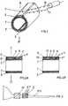
- Figure 1 shows a representation of the sensor according to the invention in the rest position;
- FIGS. 2A and 28 represent longitudinal sections through two somewhat different embodiments of the sensor;
- Figure 3 shows schematically the application of the sensor;
- FIG. 4A shows a cross section through the sensor in the rest position;
- FIG. 48 shows the sensor in cross section in a position in which the measurement signal is triggered;
- FIGS. 5A and 58 show the sensor in cross section with different adapters inserted in the rest position;
- Figure 6 shows the longitudinal section through a preferred shape of the adapter.
Diese Zeichnungen dienen als Beispiele zur Erläuterung des Erfindungsgegenstandes, der dadurch nicht auf die dargestellten Ausführungsformen beschränkt werden soll.These drawings serve as examples to explain the subject matter of the invention, which is not intended to be limited to the illustrated embodiments.
In den Figuren ist (1) ein längsgeschlitztes Rohr aus einem elastischen bzw. biegsamen und federnden Material, welches vorzugsweise dem Längsschlitz (2) gegenüberliegend eine definierte Materialschwächung (3) aufweist, die beispielsweise durch Anschleifen des Rohres in Form einer Fläche vorliegen kann. Auf dieser Fläche (3) ist ein zweckmäßig in elastisches Material eingebettetes, auf Biegung reagierendes elektromechanisches Wandlerelement (4) befestigt. Die ganze Anordnung wird gegebenenfalls von einer Abdeckung (5) umschlossen, die beispielsweise aus einer an der Außenseite elektrisch leitfähigen Folie zur elektromagnetischen Abschirmung bestehen kann. Die Abdeckung (5) kann aber auch z. B. eine elastische, dünne Folie sein, die auch als Schlauchabschnitt über die Anordnung gezogen werden und dann (in den Figuren nicht dargestellt) den Schlitz (2) mit überdecken kann. Aus dem Wandlerelement (4) wird das elektrische Signal mittels eines abgeschirmten Kabels (6, 7) zu einer - nicht zum Gegenstand der Erfindung gehörenden - elektrischen Zwischenschaltung und von da aus zur eigentlichen Beobachtungs-, Meß- oder Registrierstation geleitet, wobei die Abschirmung des Kabels (6) über die Verbindung (7) mit der gegebenenfalls vorhandenen leitfähigen Folie (5) oder auch, wenn das Rohr (1) aus Metall besteht, mit diesem elektrisch leitend verbunden ist.In the figures, (1) is a longitudinally slotted tube made of an elastic or flexible and resilient material, which preferably has a defined material weakening (3) opposite the longitudinal slot (2), which can be in the form of a surface, for example, by grinding the tube. An electromechanical transducer element (4), which is expediently embedded in elastic material and responds to bending, is fastened on this surface (3). The entire arrangement is optionally enclosed by a cover (5), which can consist, for example, of an electrically conductive foil for electromagnetic shielding on the outside. The cover (5) can also, for. B. be an elastic, thin film that can also be drawn as a tube section over the arrangement and then (not shown in the figures) cover the slot (2) with. From the transducer element (4), the electrical signal is passed by means of a shielded cable (6, 7) to an electrical intermediate circuit - not part of the subject matter of the invention - and from there to the actual observation, measuring or registration station, the shielding of the Cable (6) via the connection (7) to the conductive foil (5) which may be present or, if the tube (1) consists of metal, is connected to it in an electrically conductive manner.
Das Wandlerelement (4) ist vorzugsweise ein auf Biegung reagierender Streifen aus piezoelektrischem keramischem Werkstoff, jedoch kommen auch andere auf Biegung ansprechende Wandlerprinzipien, wie beispielsweise kapazitive, resistive, induktive oder optoelektrische in Betracht.The transducer element (4) is preferably a strip of piezoelectric ceramic material that reacts to bending, but other transducer principles that respond to bending, such as, for example, capacitive, resistive, inductive or optoelectric, can also be considered.
Das bevorzugte piezoelektrische Wandlerelement (4) wird z. B. auf die Fläche (3) geklebt oder gelötet, wobei, wenn das Rohr (1) aus einem elastischen nicht lötbaren Metall besteht, vorzugsweise ein elektrisch leitender Kleber verwendet wird.The preferred piezoelectric transducer element (4) z. B. glued or soldered to the surface (3), when the tube (1) consists of an elastic non-solderable metal, preferably an electrically conductive adhesive is used.
Wie in Figur (2A), also einem Längsschnitt in der Schnittebene A - B, dargestellt, können auch zwei parallel geschaltete Wandlerelemente (4) und (4'), die über (8) miteinander leitend verbunden sind, auf dem Rohr (1) befestigt werden. Diese können dann mit einem elastischen Material (9) vergossen werden.As shown in FIG. 2A, that is to say a longitudinal section in the sectional plane A - B, two transducer elements (4) and (4 ') connected in parallel, which are conductively connected to one another via (8), can also be placed on the tube (1). be attached. These can then be cast with an elastic material (9).
Besonders zweckmäßig ist es, entsprechend der in Figur (2B) dargestellten Ausbildungsform das Rohr (1) z. B. aus einem elastischen Kunststoff zu fertigen und dann direkt eine Verdickung (10), die Ausnehmungen (11) und (11') zum Einbau der Wandlerelemente (4) und (4') aufweist, anzuformen, wobei diese Verdikkung einschließlich der Ausnehmungen dann elektrisch leitend ausgerüstet werden kann. In diesem Fall wird gegebenenfalls im Rohrinneren unterhalb der Verdickung (10) eine Kerbe angebracht, um die erforderliche Materialschwächung zu bewirken, man kann aber auch direkt das Kunststoffrohr (1) so herstellen, daß dieses unterhalb des Sitzes der Wandlerelemente (4) und (4') dünnwandiger als an den Seitenteilen ist.It is particularly useful, according to the embodiment shown in Figure (2B), the tube (1) z. B. from an elastic plastic and then directly to form a thickening (10), the recesses (11) and (11 ') for installing the transducer elements (4) and (4'), this thickening including the recesses can be electrically conductive. In this case, a notch may be made inside the tube below the thickening (10) in order to weaken the material, but it is also possible to directly produce the plastic tube (1) so that it is below the seat of the transducer elements (4) and (4 ') is thinner than on the side parts.
Ein besonders zweckmäßiges Herstellungsverfahren eines erfindungsgemäßen Sensors besteht darin, daß man die mit den erforderlichen elektrisch leitenden Verbindungen (6, 7 und 8) versehenen Wandlerelemente (4) und (4') an die Innenwand einer mit Kern versehenen Hohlform bringt und dann das - zunächst gegebenenfalls noch nicht den Längsschlitz (2) aufweisende - Rohr (1) mit der angeformten Verdickung (10) aus Kunststoff gießt und gleichzeitig dabei die Wandlerelemente (4) und (4') darin einbettet. Nach Entnahme aus der Form wird dann gegebenenfalls noch der Längsschlitz (2) eingesägt bzw. eingefräst. Wird bei diesem Vorgehen durch entsprechende Gestaltung der Form dafür Sorge getragen, das das Rohr exzentrisch, also unterhalb des Sitzes der Wandlerelemente (4) und (4') dünnwandiger als an den Seitenteilen ist, so ist die Herstellung des erfindungsgemäßen Sensors besonders wenig arbeitsaufwendig, da - abgesehen von der Erstellung der elektrisch leitenden Verbindungen (6, 7 und 8) - keinerlei Montagearbeiten oder dergleichen erforderlich werden.A particularly expedient manufacturing method of a sensor according to the invention consists in bringing the transducer elements (4) and (4 ') provided with the required electrically conductive connections (6, 7 and 8) onto the inner wall of a hollow mold provided with a core, and then - initially possibly not yet having the longitudinal slot (2) - casting the tube (1) with the molded-on thickened portion (10) of plastic and at the same time embedding the transducer elements (4) and (4 ') therein. After removal from the mold, the longitudinal slot (2) is then optionally sawn or milled. If this procedure ensures that the tube is eccentric, that is, below the seat of the transducer elements (4) and (4 ') thinner-walled than on the side parts, the manufacture of the sensor according to the invention is special less labor intensive, since - apart from the creation of the electrically conductive connections (6, 7 and 8) - no assembly work or the like is required.
Weitere im Rahmen der Erfindung liegende Ausbildungsformen des erfindungsgemäßen Sensors ergeben sich für den Durchschnittsfachmann von selbst, d. h. ohne erfinderische Tätigkeit aus den hier gemachten Angaben und/oder den anliegenden Zeichnungen. So kann beispielsweise die (praktisch keinen Widerstand auslösende) Luft in dem Spalt (2) durch eine hochelastische, d. h. eine der Biegung des Sensors möglichst wenig Widerstand entgegensetzende Masse ausgefüllt sein, ohne daß damit eine Änderung des Konstruktionsprinzips des erfindungsgemäßen Sensors erfolgt.Further training forms of the sensor according to the invention, which are within the scope of the invention, are obvious for the average person skilled in the art. H. without inventive step from the information given here and / or the attached drawings. For example, the (practically no resistance) air in the gap (2) by a highly elastic, i.e. H. a mass opposing as little resistance as possible to the bending of the sensor can be filled in without this changing the design principle of the sensor according to the invention.
Zur Blutdruckmessung beispielsweise an der Ratte werden die Arterien des Rattenschwanzes (RS in Fig. 3) mittels einer Druckmanschette (M) an der Schwanzbasis suprasystolisch komprimiert. Der hinter der Manschette (M) auf den Rattenschwanz aufgeschobene Sensor (S) registriert dann keine Pulsationen mehr. Bei langsamen Absenken des Druckes in der Manschette werden kurz nach Unterschreiten des systolischen Druckes wieder Pulsationen, die Querschnittsänderungen des Schwanzes und damit eine im Bereich der Materialschwächung (3) eng lokalisierte Biegung bedingen (wie dies in Figuren 4A und 4B, also Querschnitten in der Schnittebene C - D, angedeutet ist), angezeigt.For blood pressure measurement, for example on the rat, the arteries of the rat tail (RS in FIG. 3) are compressed suprasystolic at the base of the tail by means of a pressure cuff (M). The sensor (S) pushed behind the cuff (M) on the rat tail then no longer registers any pulsations. If the pressure in the cuff is slowly reduced, pulsations, the changes in the cross-section of the tail and thus a localization of the curvature in the area of the material weakening (3) are required shortly after the systolic pressure is undershot (as is the case in FIGS. 4A and 4B, i.e. cross-sections in the cutting plane C - D, is indicated).
Entsprechend der Größe des Versuchstieres variiert auch der Schwanzdurchmesser und insbesondere bei chronischen Versuchen z. B. über mehrere Wochen müssen daher aufgrund des Wachstums der Tiere bekannte Pulssensoren gegen solche mit größerer lichter Weite ausgetauscht werden. Dies bedingt, daß man je Versuchstier über einen ganzen Satz von Sensoren verfügen mußte, die beispielsweise mit Innendurchmessern von 5 bis 10 mm mit einer Abstufung von je 0,5 mm Innendurchmesser (also mit 11 Sensoren je Satz) angeboten werden. Der erfindungsgemäße Sensor kann demgegenüber jeder in Betracht kommenden Schwanzdicke angepaßt werden, indem man, wie in Figuren 5A und 5B dargestellt, in das Rohr (1) Anpassungsstücke (12) einsetzt, die einen dem Schwanzdurchmesser des jeweiligen Versuchstieres entsprechenden Innendurchmesser haben und ihrerseits, wie das Rohr (1), einen Längsschlitz (2') aufweisen. Diese Anpassungsstücke übertragen die Blutdruckpulsation auf das Rohr (1), so daß dann auf die Biegung im Bereich der Materialschwächung (3) das Wandlerelement (4) anspricht.Depending on the size of the experimental animal, the tail diameter also varies, and in particular in chronic experiments, e.g. B. over several weeks, therefore, due to the growth of the animals, known pulse sensors must be replaced with those with a larger clear width. This means that one had to have a whole set of sensors for each test animal, which are offered, for example, with inner diameters of 5 to 10 mm with a gradation of 0.5 mm inner diameter (ie with 11 sensors per set). The sensor according to the invention 5A and 5B, by inserting into the tube (1) adapter pieces (12) which have an inside diameter corresponding to the tail diameter of the respective test animal and in turn, like the tube ( 1), have a longitudinal slot (2 '). These adapters transmit the blood pressure pulsation to the tube (1), so that the transducer element (4) then responds to the bend in the area of the material weakening (3).
Vorzugsweise sind an einer Seite des Anpassungsstückes (12) einige Nasen (13), wie in Figur 6 dargestellt, angeformt, die bei der Applikation des Sensors in Richtung der Manschette (M) zu liegen kommen. Diese Nasen (13) erleichtern das paßgenaue Aufschieben des Sensors mit eingesetztem Anpassungsstück und verhindern, daß, zumal bei längeren Versuchen, das Anpassungsstück (12) aus dem Rohr (1) herausrutscht oder z. B. von dem Versuchstier herausgezogen werden kann.A few lugs (13), as shown in FIG. 6, are preferably formed on one side of the adapter (12), which come to rest in the direction of the cuff (M) when the sensor is applied. These lugs (13) facilitate the precise fitting of the sensor with the adapter fitted and prevent the adapter (12) from slipping out of the tube (1), especially during longer tests, or z. B. can be pulled out of the experimental animal.
Der erfindungsgemäße Sensor kann in nahezu beliebiger Größe (Außendurchmesser und Länge) gefertigt werden, wobei aber praktische Gesichtspunkte und insbesondere die Forderung, daß die Tiere durch den Sensor möglichst wenig gestört werden sollen, gewisse Grenzen für die tatsächlich zu wählenden Maße setzen. Vorzugsweise ist die Länge des erfindungsgemäßen Sensors wenigstens gleich dessen Außendurchmesser. Seine bevorzugte Höchstlänge entspricht etwa dem Biegeradius des Schwanzes an der Meßstelle, da dann der Schwanz des Versuchstieres in seiner Beweglichkeit praktisch nicht beeinträchtigt wird und somit bei dem Tier keine Abwehr- bzw. Befreiungsaktionen und daraus resultierende Streßreaktionen ausgelöst werden. Diese bevorzugte Höchstlänge ist darüberhinaus meßtechnisch von Bedeutung, da dann durch ein Verbiegen des Schwanzes keine Kräfte auf den Sensor einwirken, die die blutdruckbedingten Änderungen des Durchmessers und damit die Anzeige überlagern oder verfälschen könnten.The sensor according to the invention can be manufactured in almost any size (outside diameter and length), but practical aspects and in particular the requirement that the animals should be disturbed as little as possible place certain limits on the dimensions actually to be selected. The length of the sensor according to the invention is preferably at least equal to its outer diameter. Its preferred maximum length corresponds approximately to the bending radius of the tail at the measuring point, since then the mobility of the tail of the test animal is practically not impaired and thus no defense or liberation actions and resulting stress reactions are triggered in the animal. This preferred maximum length is also important from a measurement point of view, since then no bending forces on the sensor act on the sensor, which could overlay or falsify the changes in the diameter caused by blood pressure and thus the display.
Claims (14)
Translated fromGermanPriority Applications (1)
| Application Number | Priority Date | Filing Date | Title |
|---|---|---|---|
| AT83113018TATE27091T1 (en) | 1983-02-24 | 1983-12-23 | SENSOR FOR DETERMINING THE SYSTOLIC BLOOD PRESSURE IN EXPERIMENTAL ANIMALS. |
Applications Claiming Priority (2)
| Application Number | Priority Date | Filing Date | Title |
|---|---|---|---|
| DE8305182 | 1983-02-24 | ||
| DE8305182U | 1983-02-24 |
Publications (2)
| Publication Number | Publication Date |
|---|---|
| EP0120137A1true EP0120137A1 (en) | 1984-10-03 |
| EP0120137B1 EP0120137B1 (en) | 1987-05-13 |
Family
ID=6750348
Family Applications (1)
| Application Number | Title | Priority Date | Filing Date |
|---|---|---|---|
| EP83113018AExpiredEP0120137B1 (en) | 1983-02-24 | 1983-12-23 | Transducer for measuring the systolic blood pressure of laboratory animals |
Country Status (3)
| Country | Link |
|---|---|
| EP (1) | EP0120137B1 (en) |
| AT (1) | ATE27091T1 (en) |
| DE (1) | DE3371464D1 (en) |
Cited By (4)
| Publication number | Priority date | Publication date | Assignee | Title |
|---|---|---|---|---|
| WO1988004042A1 (en)* | 1986-11-27 | 1988-06-02 | Ford Motor Co | Monitoring fluid pressure in a flexible pipe |
| AU611324B2 (en)* | 1988-09-22 | 1991-06-06 | Kabushiki Kaisha Toyota Chuo Kenkyusho | Disposable pressure transducer and disposable pressure transducer apparatus |
| GB2258312A (en)* | 1991-07-29 | 1993-02-03 | Colin Electronics | Pressure pulse wave transmitting sheet for pulse wave sensor |
| US5307811A (en)* | 1990-06-11 | 1994-05-03 | Radi Medical Systems Ab | Femoral compression device |
Citations (5)
| Publication number | Priority date | Publication date | Assignee | Title |
|---|---|---|---|---|
| US3149492A (en)* | 1961-03-06 | 1964-09-22 | Astra Inc | Fluid pressure gauge |
| US4122843A (en)* | 1977-08-10 | 1978-10-31 | Electro-Technics, Inc. | Electrode system for a heart rate monitor |
| DE2848198A1 (en)* | 1978-11-07 | 1980-05-08 | Ernst Piffl | Blood pressure monitor using arterial tonometer method - has two piezoelectric sensors monitoring artery expansion and compensating for movement of patient |
| US4256094A (en)* | 1979-06-18 | 1981-03-17 | Kapp John P | Arterial pressure control system |
| GB2073889A (en)* | 1980-03-19 | 1981-10-21 | List H | Transducer device for measuring mechanical values on hollow bodies |
- 1983
- 1983-12-23ATAT83113018Tpatent/ATE27091T1/enactive
- 1983-12-23DEDE8383113018Tpatent/DE3371464D1/ennot_activeExpired
- 1983-12-23EPEP83113018Apatent/EP0120137B1/ennot_activeExpired
Patent Citations (5)
| Publication number | Priority date | Publication date | Assignee | Title |
|---|---|---|---|---|
| US3149492A (en)* | 1961-03-06 | 1964-09-22 | Astra Inc | Fluid pressure gauge |
| US4122843A (en)* | 1977-08-10 | 1978-10-31 | Electro-Technics, Inc. | Electrode system for a heart rate monitor |
| DE2848198A1 (en)* | 1978-11-07 | 1980-05-08 | Ernst Piffl | Blood pressure monitor using arterial tonometer method - has two piezoelectric sensors monitoring artery expansion and compensating for movement of patient |
| US4256094A (en)* | 1979-06-18 | 1981-03-17 | Kapp John P | Arterial pressure control system |
| GB2073889A (en)* | 1980-03-19 | 1981-10-21 | List H | Transducer device for measuring mechanical values on hollow bodies |
Non-Patent Citations (1)
| Title |
|---|
| JOURNAL OF APPLIED PHYSIOLOGY, Band 25, Nr. 6, Dezember 1968, Seiten 772-773, US* |
Cited By (6)
| Publication number | Priority date | Publication date | Assignee | Title |
|---|---|---|---|---|
| WO1988004042A1 (en)* | 1986-11-27 | 1988-06-02 | Ford Motor Co | Monitoring fluid pressure in a flexible pipe |
| AU611324B2 (en)* | 1988-09-22 | 1991-06-06 | Kabushiki Kaisha Toyota Chuo Kenkyusho | Disposable pressure transducer and disposable pressure transducer apparatus |
| US5307811A (en)* | 1990-06-11 | 1994-05-03 | Radi Medical Systems Ab | Femoral compression device |
| GB2258312A (en)* | 1991-07-29 | 1993-02-03 | Colin Electronics | Pressure pulse wave transmitting sheet for pulse wave sensor |
| US5269312A (en)* | 1991-07-29 | 1993-12-14 | Colin Electronics Co., Ltd. | Pressure pulse wave transmitting sheet used with pressure pulse wave sensor |
| GB2258312B (en)* | 1991-07-29 | 1995-07-12 | Colin Electronics | Pressure pulse wave transmitting sheet used with pressure pulse wave sensor |
Also Published As
| Publication number | Publication date |
|---|---|
| DE3371464D1 (en) | 1987-06-19 |
| EP0120137B1 (en) | 1987-05-13 |
| ATE27091T1 (en) | 1987-05-15 |
Similar Documents
| Publication | Publication Date | Title |
|---|---|---|
| EP0001127B1 (en) | Apparatus comprising a generator for mechanical vibrations of adjustable frequenz and a receptor of vibrations for determining the natural frequency of blood vessels or tendons in a live body | |
| DE69026176T2 (en) | Holder for a catheter sensor and application method | |
| DE102007046384A1 (en) | Measuring device for measuring a bend and a twist | |
| EP0042371A1 (en) | Detector for the measurement of deformations on hollow bodies | |
| EP0501041B1 (en) | Procedure and device for cable tension measurement | |
| EP1754509B1 (en) | Implant for the insertion into a hollow body | |
| CH617770A5 (en) | ||
| EP1139871B1 (en) | Device and method for measuring the periphery of a body | |
| DE3103163A1 (en) | MEASURING DEVICE FOR DETERMINING THE STRENGTH OF TISSUES | |
| DE102017202896B4 (en) | Flow measuring device and transmitter for process instrumentation with such a flow measuring device | |
| EP0120137B1 (en) | Transducer for measuring the systolic blood pressure of laboratory animals | |
| DE69522864T2 (en) | Measuring instrument for determining the degree of relaxation | |
| DE2145198C3 (en) | Pressure receptor | |
| EP1329192B1 (en) | X-ray device | |
| DE2646018B2 (en) | Pulse monitoring device | |
| DE60129966T2 (en) | COLLISION TEST DEVICE | |
| DE3019464A1 (en) | MINIATURE PRESSURE CONVERTER | |
| DE112017004103T5 (en) | IN VIVO SIGNAL SOURCE DETECTION PROCEDURE AND IN VIVO SIGNAL SOURCE DETECTION DEVICE | |
| DE19605036C2 (en) | Rope load cell | |
| DE8305182U1 (en) | Sensor for determining the systolic blood pressure in test animals | |
| DE102016008472A1 (en) | Electrode probe for the detection of moisture | |
| WO2004015408A1 (en) | Method for producing ph probes | |
| DE3936525A1 (en) | Force and torque measuring device esp. for armature spindle - contains strain gauges on removable inelastic metal strip round spindle | |
| DE102005018568A1 (en) | Pedestrian protection vehicle impact severity sensor uses tension transmitter under flexible tubular cover along car bumper | |
| Bergner et al. | Virtuelle akustische Umgebungen zur Förderung von mentaler Gesundheit |
Legal Events
| Date | Code | Title | Description |
|---|---|---|---|
| PUAI | Public reference made under article 153(3) epc to a published international application that has entered the european phase | Free format text:ORIGINAL CODE: 0009012 | |
| AK | Designated contracting states | Designated state(s):AT BE CH DE FR GB IT LI NL SE | |
| 17P | Request for examination filed | Effective date:19841126 | |
| 17Q | First examination report despatched | Effective date:19860127 | |
| GRAA | (expected) grant | Free format text:ORIGINAL CODE: 0009210 | |
| RAP1 | Party data changed (applicant data changed or rights of an application transferred) | Owner name:GRUENENTHAL GMBH | |
| AK | Designated contracting states | Kind code of ref document:B1 Designated state(s):AT BE CH DE FR GB IT LI NL SE | |
| PG25 | Lapsed in a contracting state [announced via postgrant information from national office to epo] | Ref country code:NL Effective date:19870513 Ref country code:IT Free format text:LAPSE BECAUSE OF FAILURE TO SUBMIT A TRANSLATION OF THE DESCRIPTION OR TO PAY THE FEE WITHIN THE PRESCRIBED TIME-LIMIT;WARNING: LAPSES OF ITALIAN PATENTS WITH EFFECTIVE DATE BEFORE 2007 MAY HAVE OCCURRED AT ANY TIME BEFORE 2007. THE CORRECT EFFECTIVE DATE MAY BE DIFFERENT FROM THE ONE RECORDED. Effective date:19870513 Ref country code:FR Free format text:THE PATENT HAS BEEN ANNULLED BY A DECISION OF A NATIONAL AUTHORITY Effective date:19870513 Ref country code:BE Effective date:19870513 | |
| REF | Corresponds to: | Ref document number:27091 Country of ref document:AT Date of ref document:19870515 Kind code of ref document:T | |
| PG25 | Lapsed in a contracting state [announced via postgrant information from national office to epo] | Ref country code:SE Effective date:19870531 | |
| REF | Corresponds to: | Ref document number:3371464 Country of ref document:DE Date of ref document:19870619 | |
| EN | Fr: translation not filed | ||
| NLV1 | Nl: lapsed or annulled due to failure to fulfill the requirements of art. 29p and 29m of the patents act | ||
| PLBE | No opposition filed within time limit | Free format text:ORIGINAL CODE: 0009261 | |
| STAA | Information on the status of an ep patent application or granted ep patent | Free format text:STATUS: NO OPPOSITION FILED WITHIN TIME LIMIT | |
| 26N | No opposition filed | ||
| PG25 | Lapsed in a contracting state [announced via postgrant information from national office to epo] | Ref country code:GB Effective date:19881223 | |
| GBPC | Gb: european patent ceased through non-payment of renewal fee | ||
| REG | Reference to a national code | Ref country code:CH Ref legal event code:PUE Owner name:MECHTHILD HESS UND DR. VOLKER HESS MESSTECHNIK | |
| PGFP | Annual fee paid to national office [announced via postgrant information from national office to epo] | Ref country code:AT Payment date:19911230 Year of fee payment:9 | |
| PG25 | Lapsed in a contracting state [announced via postgrant information from national office to epo] | Ref country code:AT Effective date:19921223 | |
| PGFP | Annual fee paid to national office [announced via postgrant information from national office to epo] | Ref country code:DE Payment date:19930423 Year of fee payment:10 | |
| PGFP | Annual fee paid to national office [announced via postgrant information from national office to epo] | Ref country code:CH Payment date:19940120 Year of fee payment:11 | |
| PG25 | Lapsed in a contracting state [announced via postgrant information from national office to epo] | Ref country code:DE Effective date:19940901 | |
| PG25 | Lapsed in a contracting state [announced via postgrant information from national office to epo] | Ref country code:LI Effective date:19941231 Ref country code:CH Effective date:19941231 | |
| REG | Reference to a national code | Ref country code:CH Ref legal event code:PL |