EP0120108B1 - Electrochemical cell for determining a particular component of a fluid - Google Patents
Electrochemical cell for determining a particular component of a fluidDownload PDFInfo
- Publication number
- EP0120108B1 EP0120108B1EP19830102976EP83102976AEP0120108B1EP 0120108 B1EP0120108 B1EP 0120108B1EP 19830102976EP19830102976EP 19830102976EP 83102976 AEP83102976 AEP 83102976AEP 0120108 B1EP0120108 B1EP 0120108B1
- Authority
- EP
- European Patent Office
- Prior art keywords
- cell according
- membrane
- substrate
- fluid
- cathode
- Prior art date
- Legal status (The legal status is an assumption and is not a legal conclusion. Google has not performed a legal analysis and makes no representation as to the accuracy of the status listed.)
- Expired
Links
Images

Classifications
- A—HUMAN NECESSITIES
- A61—MEDICAL OR VETERINARY SCIENCE; HYGIENE
- A61B—DIAGNOSIS; SURGERY; IDENTIFICATION
- A61B5/00—Measuring for diagnostic purposes; Identification of persons
- A61B5/145—Measuring characteristics of blood in vivo, e.g. gas concentration or pH-value ; Measuring characteristics of body fluids or tissues, e.g. interstitial fluid or cerebral tissue
- A61B5/14542—Measuring characteristics of blood in vivo, e.g. gas concentration or pH-value ; Measuring characteristics of body fluids or tissues, e.g. interstitial fluid or cerebral tissue for measuring blood gases
- A—HUMAN NECESSITIES
- A61—MEDICAL OR VETERINARY SCIENCE; HYGIENE
- A61B—DIAGNOSIS; SURGERY; IDENTIFICATION
- A61B5/00—Measuring for diagnostic purposes; Identification of persons
- A61B5/145—Measuring characteristics of blood in vivo, e.g. gas concentration or pH-value ; Measuring characteristics of body fluids or tissues, e.g. interstitial fluid or cerebral tissue
- A61B5/1468—Measuring characteristics of blood in vivo, e.g. gas concentration or pH-value ; Measuring characteristics of body fluids or tissues, e.g. interstitial fluid or cerebral tissue using chemical or electrochemical methods, e.g. by polarographic means
- A61B5/1473—Measuring characteristics of blood in vivo, e.g. gas concentration or pH-value ; Measuring characteristics of body fluids or tissues, e.g. interstitial fluid or cerebral tissue using chemical or electrochemical methods, e.g. by polarographic means invasive, e.g. introduced into the body by a catheter
- G—PHYSICS
- G01—MEASURING; TESTING
- G01N—INVESTIGATING OR ANALYSING MATERIALS BY DETERMINING THEIR CHEMICAL OR PHYSICAL PROPERTIES
- G01N27/00—Investigating or analysing materials by the use of electric, electrochemical, or magnetic means
- G01N27/26—Investigating or analysing materials by the use of electric, electrochemical, or magnetic means by investigating electrochemical variables; by using electrolysis or electrophoresis
- G01N27/403—Cells and electrode assemblies
- G01N27/404—Cells with anode, cathode and cell electrolyte on the same side of a permeable membrane which separates them from the sample fluid, e.g. Clark-type oxygen sensors
Definitions
- the inventionrelates to an electrochemical cell in accordance with the general portion of claim 1, and known from Mesures-Regulation-Automatisme, vol. 46, No. 5, May 1981, Paris "Des techniques microartniques pour un capteur d'oxygene dissous", page 85.
- Cells of this typeare for instance used for determining the oxygen content of a fluid such as blood or air.
- a well-known type of this cellis the so-called Clark Cell as described in US-A-29 13386.
- a miniaturized cell of this typehas been proposed in EP-A-103031 (published 21.03.84) wherein a thin layer of hydrophylic polymer is provided between a non-porous membrane and the electrodes and covers at least the cathode.
- the membranehas at least one hole in it for allowing an electrolytic component of the fluid to enter said hydrophylic polymer layer, whereat the electrolyte is supplied by the fluid under measurement.
- a tube-like housing 1 made of metal, glass, plastic or preferably made of ceramicsis supported by an adaptor base plate 2, by means of which the sensor can be attached to a thermostatically controlled part 3 of the mouthpiece of a respiration system.
- a heating coil 27surrounds these sensor portions of housing 1 when inserted into part 3.
- a temperature controller(not shown) accomplished a uniform temperature of the sensor portion during measurement.
- Housing 1forms an electrolyte compartment 4 which is closed at the rearward end by means of a plate 5 having a filling opening 6, which after filling is closed by a plug 7 or otherwise.
- a supporting structure 8 of semicircular cross sectionis provided in the front end opening of housing 1 and supports a semiconductor substrate 9 forming the active portion of the sensor. The remaining area of the front end surface of housing 1 is closed by a plate 10.
- Substrate 9carries a cathode layer 20 deposited on substrate 9 by the well-known technology of printed circuits, thin film or thick film procedures.
- the cathode portion 20 and part of the substrate 9are covered by a layer 12 consisting of a hydrophylic matrix polymer or hydrogel.
- a selectively permable membrane 13covers layer 12, whereat inside housing 1 a portion 14 of layer 12 is not covered by the membrane and is directly exposed to the electrolyte in compartment 4.
- Substrate 9may also carry an integrated temperature sensor 15 (see Fig. 2) and if required, a heater (not shown) which in a similar manner like the cathode layer can be deposited by thin film or thick film technology.
- the heater 27is located in part 3.
- Electrical connectors 16are provided on the substrate for connecting the cathode, the anode, the temperature sensor and the heater to an external measuring and supply circuit by means of a cable 17 and connector pins 18.
- the contact area 16is covered and electrically insulated by a protective layer 19 consisting of silicone rubber or any other suitable material.
- the cathode 20might be provided as a thin layer between two anode layers 11 on substrate 9 (see Fig. 2).
- the anodecan also be formed by a separate anode 11 a projecting into the electrolyte compartment 4 (see Fig. 1).
- the hydrophylic matrix polymer layer 12by its capillary action forms a salt bridge between the electrolyte compartment 4 and the cathode layer 20.
- Membrane 13which limits the diffusion of gas to the cathode area of substrate 9 can be produced by a combination of centrifugal spinning technique and lithography which is well-known in the field of thin film technology. By this technology extremely thin membranes can be made in the order of less than 1 p which leads to a very fast response of the sensor. Other depositing techniques suitable for producing the membrane are spraying, flow coating, silk screening, condensation out of the gas phase, grafting and sputtering. Electrolyte compartment 4 contains a sufficient amount of electrolyte for achieving a long operation time of the sensor.
- the temperature sensor 15allows compensation of the temperature dependency of the sensor by means of the electrical monitoring and measuring circuitry connected to terminals 18.
- the hydrophylic polymer layer 12forms a salt bridge for the electrolyte.
- Substrate 9preferably made of a semiconducting material such as silicon may also include an integrated amplifier to overcome problems which during long term operation may be caused by parasitic insulation currents or electrostatic effects.
- the sensorcan be stored dry, and the electrolyte filled in shortly before the sensor will be used.
- the electrolyte within compartment 4then by means of the capillary action of hydrophylic polymer layer 12 is brought to the cathode (and anode) area on substrate 9, therewith activating the sensor.
- the sensoris used as a polaro- graphic oxygen sensor, the oxygen surrounding the outwardly projecting portion of substrate 9 will diffuse through membrane 13 and the hydrophylic matrix polymer layer 12 to the cathode and will react at the cathode as follows:
- the corresponding reaction at the anodecan be described by in case a silver anode and a chloride containing electrolyte are used. Both the chloride and the hydroxyl ions will be transported from and to the electrolyte compartment 4 via the hydrophylic matrix polymer layer 12.
- the use of separate anode 11a aprovides a longer lifetime of the sensor compared with an anode 11 provided on the substrate 9 because the amount of anode material is an essential factor for the timelife.
- the sensorhas a small response time, in particular less than one second, and therewith can be used for monitoring quickly changing oxygen content in a gas stream.
- the new sensorcan also be used for measuring the content of oxygen or another component of a liquid.
- Figures 3 and 4show an embodiment in which the sensor is located in the tip portion of a catheter 1.
- the supporting structure 8preferably made of glass or another suitable material carries substrate 9 together with cathode layer 20, hydrophylic matrix polymer layer 12 and membrane 13.
- the front end portion of closed tube 1is filled with epoxy resin or silicone rubber 21.
- a hole 22 provided at the circumferential wall of tube 1allows the liquid to engage membrane 13 so that oxygen ions can diffuse through membrane 13 and polymer layer 12 to anode 11.
- An intermediate wall 23closes electrolyte compartment 4 against the. sensor portion of the catheter.
- the anodemight be provided on the substrates 9 or as shown in Figure 3 may be a separate anode 11 a held in a supporting tube 24 within catheter 1.
- Cable 17 and supporting tube 24are sealed against tube 1 by epoxy resin seals 25, therewith closing electrolyte compartment 4 at the other end. Similar sealings are provided at 26 in the area where cable 17 is connected to substrate 9.
- An opening provided in seal 25allows filling compartment 4 with an electrolyte and is thereafter closed by a plug 7.
- This type of catheter sensorcan also be used for ion-selective and enzymatic sensor constructions.
- membrane 13contains special organic molecules and forms a so-called liquid ion membrane.
- Such liquid ion membrane materialscan also be deposited on top of the hydrogel layer 12 by means of lithographic technology.
- Liquid ion membranesconstitute an effective means for sensing different types of organic components of biological liquids. The use of such liquid ion membranes is described in an article "lon-Selective Electrodes in Clinical Chemistry" published in Medical Progress Through Technology 5.1-12 (1977), pages 1-10, in particular page 4. Since this kind of application involves measuring the difference of electrical potential across a high impedance membrane, environmental electrical disturbance signals may influence the measuring signal which further could be decreased by insulation leakage.
- the silver/silver chloride electrodecan be connected to the input of an impedance converter, e.g. to the gate electrode if a field effect transistor, therewith converting the high impedance measuring signal to a low impedance output signal.
- the silver/silver chloride reference electrodecan be situated outside the membrane at various positions, e.g. on the substrate, in the lumen of a catheter which is continuously flushed with saline or in the bag or bottle containing the saline.
- the inventionleads to a versatile sensor construction, which may be used for sensing various types of components of gaseous or liquid fluids, has a fast response, can easily be miniaturized and produced in large quantities by the well-known technology of integrated circuits, lithography and thin film methods.
Landscapes
- Life Sciences & Earth Sciences (AREA)
- Health & Medical Sciences (AREA)
- Physics & Mathematics (AREA)
- Pathology (AREA)
- General Health & Medical Sciences (AREA)
- Molecular Biology (AREA)
- Chemical & Material Sciences (AREA)
- Optics & Photonics (AREA)
- Surgery (AREA)
- Veterinary Medicine (AREA)
- Public Health (AREA)
- Animal Behavior & Ethology (AREA)
- Medical Informatics (AREA)
- Heart & Thoracic Surgery (AREA)
- Chemical Kinetics & Catalysis (AREA)
- Biophysics (AREA)
- Engineering & Computer Science (AREA)
- Biomedical Technology (AREA)
- General Chemical & Material Sciences (AREA)
- Electrochemistry (AREA)
- Biochemistry (AREA)
- Immunology (AREA)
- General Physics & Mathematics (AREA)
- Analytical Chemistry (AREA)
- Measurement Of The Respiration, Hearing Ability, Form, And Blood Characteristics Of Living Organisms (AREA)
Description
- The invention relates to an electrochemical cell in accordance with the general portion of claim 1, and known from Mesures-Regulation-Automatisme, vol. 46, No. 5, May 1981, Paris "Des techniques microélectroniques pour un capteur d'oxygene dissous", page 85. Cells of this type are for instance used for determining the oxygen content of a fluid such as blood or air. A well-known type of this cell is the so-called Clark Cell as described in US-A-29 13386. For medical and biological applications a miniaturized cell of this type has been proposed in EP-A-103031 (published 21.03.84) wherein a thin layer of hydrophylic polymer is provided between a non-porous membrane and the electrodes and covers at least the cathode. The membrane has at least one hole in it for allowing an electrolytic component of the fluid to enter said hydrophylic polymer layer, whereat the electrolyte is supplied by the fluid under measurement. It is further known from Medical & Biological Engineering & Computing, Vol. 18, No. 6, February 1980, Stevenage K. Shimada et al. "Application of catheter-tip i.s.f.e.t. for continuous in vivo measurement", pages 741-745, to use a hydrogel polymer to improve the blood combatibility, the response time and the reproducibility of a catheter-tip pH sensor.
- It is the main object of the present invention to provide an electrochemical cell of the above- mentioned type having a very short response time such that it can be used for-the measurement of quickly changing components in a fluid such as the oxygen content or oxygen-partial pressure during respiration.
- Also this new cell should be capable of being miniaturized and should be suitable for medical and biological applications, i.e. sterilization should be no problem. These objects and further improvements are accomplished by the invention as characterized in claim 1. Preferred embodiments and improvements are described in the sub-claims.
- The invention will be described in more detail with reference to the accompanying drawings in which
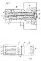
- Fig. 1 shows an electrochemical cell for measuring the oxygen-partial pressure in a gaseous fluid, e.g. in the respiration air;
- Fig. 2 shows at an enlarged scale a top view on the sensor chip;
- Fig. 3 is a sectional view of the cell provided in a catheter; and
- Fig. 4 is a cross sectional view taken along line IV-IV of Fig. 3.
- In Fig. 1 a tube-like housing 1 made of metal, glass, plastic or preferably made of ceramics is supported by an
adaptor base plate 2, by means of which the sensor can be attached to a thermostatically controlled part 3 of the mouthpiece of a respiration system. Aheating coil 27 surrounds these sensor portions of housing 1 when inserted into part 3. A temperature controller (not shown) accomplished a uniform temperature of the sensor portion during measurement. Housing 1 forms anelectrolyte compartment 4 which is closed at the rearward end by means of aplate 5 having a filling opening 6, which after filling is closed by aplug 7 or otherwise. A supporting structure 8 of semicircular cross section is provided in the front end opening of housing 1 and supports asemiconductor substrate 9 forming the active portion of the sensor. The remaining area of the front end surface of housing 1 is closed by a plate 10. Substrate 9 carries a cathode layer 20 deposited onsubstrate 9 by the well-known technology of printed circuits, thin film or thick film procedures. The cathode portion 20 and part of thesubstrate 9 are covered by alayer 12 consisting of a hydrophylic matrix polymer or hydrogel. A selectivelypermable membrane 13 coverslayer 12, whereat inside housing 1 aportion 14 oflayer 12 is not covered by the membrane and is directly exposed to the electrolyte incompartment 4.Substrate 9 may also carry an integrated temperature sensor 15 (see Fig. 2) and if required, a heater (not shown) which in a similar manner like the cathode layer can be deposited by thin film or thick film technology. Preferably theheater 27 is located in part 3.Electrical connectors 16 are provided on the substrate for connecting the cathode, the anode, the temperature sensor and the heater to an external measuring and supply circuit by means of acable 17 andconnector pins 18. Thecontact area 16 is covered and electrically insulated by a protective layer 19 consisting of silicone rubber or any other suitable material. The cathode 20 might be provided as a thin layer between twoanode layers 11 on substrate 9 (see Fig. 2). The anode can also be formed by a separate anode 11 a projecting into the electrolyte compartment 4 (see Fig. 1). The hydrophylicmatrix polymer layer 12 by its capillary action forms a salt bridge between theelectrolyte compartment 4 and the cathode layer 20.Membrane 13 which limits the diffusion of gas to the cathode area ofsubstrate 9 can be produced by a combination of centrifugal spinning technique and lithography which is well-known in the field of thin film technology. By this technology extremely thin membranes can be made in the order of less than 1 p which leads to a very fast response of the sensor. Other depositing techniques suitable for producing the membrane are spraying, flow coating, silk screening, condensation out of the gas phase, grafting and sputtering.Electrolyte compartment 4 contains a sufficient amount of electrolyte for achieving a long operation time of the sensor. The temperature sensor 15 allows compensation of the temperature dependency of the sensor by means of the electrical monitoring and measuring circuitry connected toterminals 18. If a separate anode 11a is used instead of ananode 11 provided on thesubstrate 9 itself, thehydrophylic polymer layer 12 forms a salt bridge for the electrolyte.Substrate 9 preferably made of a semiconducting material such as silicon may also include an integrated amplifier to overcome problems which during long term operation may be caused by parasitic insulation currents or electrostatic effects.- The sensor can be stored dry, and the electrolyte filled in shortly before the sensor will be used. The electrolyte within
compartment 4 then by means of the capillary action ofhydrophylic polymer layer 12 is brought to the cathode (and anode) area onsubstrate 9, therewith activating the sensor. If the sensor is used as a polaro- graphic oxygen sensor, the oxygen surrounding the outwardly projecting portion ofsubstrate 9 will diffuse throughmembrane 13 and the hydrophylicmatrix polymer layer 12 to the cathode and will react at the cathode as follows:
- The corresponding reaction at the anode can be described by

electrolyte compartment 4 via the hydrophylicmatrix polymer layer 12. The use of separate anode 11a a provides a longer lifetime of the sensor compared with ananode 11 provided on thesubstrate 9 because the amount of anode material is an essential factor for the timelife. The sensor has a small response time, in particular less than one second, and therewith can be used for monitoring quickly changing oxygen content in a gas stream. - The new sensor can also be used for measuring the content of oxygen or another component of a liquid. Figures 3 and 4 show an embodiment in which the sensor is located in the tip portion of a catheter 1. The supporting structure 8 preferably made of glass or another suitable material carries
substrate 9 together with cathode layer 20, hydrophylicmatrix polymer layer 12 andmembrane 13. The front end portion of closed tube 1 is filled with epoxy resin orsilicone rubber 21. Ahole 22 provided at the circumferential wall of tube 1 allows the liquid to engagemembrane 13 so that oxygen ions can diffuse throughmembrane 13 andpolymer layer 12 toanode 11. Anintermediate wall 23 closeselectrolyte compartment 4 against the. sensor portion of the catheter. The anode might be provided on thesubstrates 9 or as shown in Figure 3 may be a separate anode 11 a held in a supporting tube 24 within catheter 1.Cable 17 and supporting tube 24 are sealed against tube 1 byepoxy resin seals 25, therewithclosing electrolyte compartment 4 at the other end. Similar sealings are provided at 26 in the area wherecable 17 is connected tosubstrate 9. An opening provided inseal 25 allowsfilling compartment 4 with an electrolyte and is thereafter closed by aplug 7. - This type of catheter sensor can also be used for ion-selective and enzymatic sensor constructions. In these
cases membrane 13 contains special organic molecules and forms a so-called liquid ion membrane. Such liquid ion membrane materials can also be deposited on top of thehydrogel layer 12 by means of lithographic technology. Liquid ion membranes constitute an effective means for sensing different types of organic components of biological liquids. The use of such liquid ion membranes is described in an article "lon-Selective Electrodes in Clinical Chemistry" published in Medical Progress Through Technology 5.1-12 (1977), pages 1-10, inparticular page 4. Since this kind of application involves measuring the difference of electrical potential across a high impedance membrane, environmental electrical disturbance signals may influence the measuring signal which further could be decreased by insulation leakage. To overcome these problems an impendance conversion of the measuring signal is helpful. For this purpose the silver/silver chloride electrode can be connected to the input of an impedance converter, e.g. to the gate electrode if a field effect transistor, therewith converting the high impedance measuring signal to a low impedance output signal. The silver/silver chloride reference electrode can be situated outside the membrane at various positions, e.g. on the substrate, in the lumen of a catheter which is continuously flushed with saline or in the bag or bottle containing the saline. - The invention leads to a versatile sensor construction, which may be used for sensing various types of components of gaseous or liquid fluids, has a fast response, can easily be miniaturized and produced in large quantities by the well-known technology of integrated circuits, lithography and thin film methods.
- It is not restricted to medical applications but can also be used in the field of industrial process monitoring and control, bio-technology, environmental protection and for other purposes. Other components of a gaseous or liquid medium (fluid) than those as described above may be monitored or searched-for by the sensor.


Claims (13)
Priority Applications (2)
| Application Number | Priority Date | Filing Date | Title |
|---|---|---|---|
| EP19830102976EP0120108B1 (en) | 1983-03-25 | 1983-03-25 | Electrochemical cell for determining a particular component of a fluid |
| DE8383102976TDE3365237D1 (en) | 1983-03-25 | 1983-03-25 | Electrochemical cell for determining a particular component of a fluid |
Applications Claiming Priority (1)
| Application Number | Priority Date | Filing Date | Title |
|---|---|---|---|
| EP19830102976EP0120108B1 (en) | 1983-03-25 | 1983-03-25 | Electrochemical cell for determining a particular component of a fluid |
Publications (2)
| Publication Number | Publication Date |
|---|---|
| EP0120108A1 EP0120108A1 (en) | 1984-10-03 |
| EP0120108B1true EP0120108B1 (en) | 1986-08-13 |
Family
ID=8190374
Family Applications (1)
| Application Number | Title | Priority Date | Filing Date |
|---|---|---|---|
| EP19830102976ExpiredEP0120108B1 (en) | 1983-03-25 | 1983-03-25 | Electrochemical cell for determining a particular component of a fluid |
Country Status (2)
| Country | Link |
|---|---|
| EP (1) | EP0120108B1 (en) |
| DE (1) | DE3365237D1 (en) |
Families Citing this family (7)
| Publication number | Priority date | Publication date | Assignee | Title |
|---|---|---|---|---|
| GB8501039D0 (en)* | 1985-01-16 | 1985-02-20 | Neotronics Ltd | Gas sensor |
| FR2578056B1 (en)* | 1985-02-22 | 1988-08-26 | Tacussel Jacques | PROBE FOR SIMULTANEOUS MEASUREMENT OF ION ACTIVITY AND TEMPERATURE OF A MEDIUM |
| US4741343A (en)* | 1985-05-06 | 1988-05-03 | Massachusetts Institute Of Technology | Method and apparatus for measuring oxygen partial pressure and temperature in living tissue |
| DE3774680D1 (en)* | 1986-12-22 | 1992-01-02 | Siemens Ag | ARRANGEMENT FOR EXAMINING A LIQUID MEDIUM AND METHOD FOR OPERATING THE ARRANGEMENT. |
| GB8725936D0 (en)* | 1987-11-05 | 1987-12-09 | Genetics Int Inc | Sensing system |
| GB8819086D0 (en)* | 1988-08-11 | 1988-09-14 | Univ Wales Medicine | "in-vivo"oxygen tension measurement |
| EP2179691A1 (en)* | 2008-10-23 | 2010-04-28 | General Electric Company | Gas analyzing unit and airway adapter |
Family Cites Families (2)
| Publication number | Priority date | Publication date | Assignee | Title |
|---|---|---|---|---|
| GB1505343A (en)* | 1973-12-18 | 1978-03-30 | Butler J | Electrochemical cells |
| DE2849209C2 (en)* | 1978-11-13 | 1983-02-03 | Hans-Jürgen 4630 Bochum Gräbner | Electrochemical diffusion measuring cell |
- 1983
- 1983-03-25EPEP19830102976patent/EP0120108B1/ennot_activeExpired
- 1983-03-25DEDE8383102976Tpatent/DE3365237D1/ennot_activeExpired
Also Published As
| Publication number | Publication date |
|---|---|
| EP0120108A1 (en) | 1984-10-03 |
| DE3365237D1 (en) | 1986-09-18 |
Similar Documents
| Publication | Publication Date | Title |
|---|---|---|
| AU625758B2 (en) | Precalibrated, disposable, electrochemical sensors | |
| US4197853A (en) | PO2 /PCO2 sensor | |
| US5846392A (en) | Miniaturized circulatory measuring chamber with integrated chemo- and/or biosensor elements | |
| US4020830A (en) | Selective chemical sensitive FET transducers | |
| US3719576A (en) | Electrode for measuring co2 tension in blood and other liquid and gaseous environments | |
| US4062750A (en) | Thin film electrochemical electrode and cell | |
| US6176988B1 (en) | Membrane electrode for measuring the glucose concentration in fluids | |
| US4871439A (en) | Disposable self-calibratable electrode package | |
| US4176659A (en) | Catheter with measurement electrodes | |
| US9791398B2 (en) | Measurement device with sensor array | |
| US9528959B2 (en) | Method and apparatus for measuring oxidation-reduction potential | |
| US3824157A (en) | Method of equilibrating and calibrating a partial pressure gas sensor | |
| US5384031A (en) | Reference electrode | |
| EP0120108B1 (en) | Electrochemical cell for determining a particular component of a fluid | |
| Karagounis et al. | A thick-film multiple component cathode three-electrode oxygen sensor | |
| JPH07109413B2 (en) | Chemically sensitive transducer | |
| EP0068025B1 (en) | Reference electrode | |
| JP2867323B2 (en) | Dissolved oxygen electrode | |
| GB2030706A (en) | Electrochemical sensor and method of calibration thereof | |
| Esashi et al. | Solid-state micro sensors | |
| JPS63117728A (en) | Ion sensor | |
| AU2016200041A1 (en) | Measurement device with sensor array | |
| JPS5994059A (en) | Sensors for measuring various components | |
| CS262057B1 (en) | Micro probe for long-term measurement of oxygen partial pressure in tissues in gaseous and aqueous media | |
| HK1188823B (en) | Apparatus for measuring oxidation-reduction potential |
Legal Events
| Date | Code | Title | Description |
|---|---|---|---|
| PUAI | Public reference made under article 153(3) epc to a published international application that has entered the european phase | Free format text:ORIGINAL CODE: 0009012 | |
| 17P | Request for examination filed | Effective date:19840613 | |
| AK | Designated contracting states | Kind code of ref document:A1 Designated state(s):CH DE FR GB IT LI NL SE | |
| RAP1 | Party data changed (applicant data changed or rights of an application transferred) | Owner name:HONEYWELL MEDICAL ELECTRONICS B.V. | |
| GRAA | (expected) grant | Free format text:ORIGINAL CODE: 0009210 | |
| AK | Designated contracting states | Kind code of ref document:B1 Designated state(s):CH DE FR GB IT LI NL SE | |
| REF | Corresponds to: | Ref document number:3365237 Country of ref document:DE Date of ref document:19860918 | |
| ITF | It: translation for a ep patent filed | ||
| ET | Fr: translation filed | ||
| PLBE | No opposition filed within time limit | Free format text:ORIGINAL CODE: 0009261 | |
| STAA | Information on the status of an ep patent application or granted ep patent | Free format text:STATUS: NO OPPOSITION FILED WITHIN TIME LIMIT | |
| 26N | No opposition filed | ||
| REG | Reference to a national code | Ref country code:CH Ref legal event code:PFA Free format text:PPG HELLIGE B.V. | |
| REG | Reference to a national code | Ref country code:FR Ref legal event code:CD | |
| NLT1 | Nl: modifications of names registered in virtue of documents presented to the patent office pursuant to art. 16 a, paragraph 1 | Owner name:PPG HELLIGE B.V. TE BEST. | |
| ITTA | It: last paid annual fee | ||
| ITPR | It: changes in ownership of a european patent | Owner name:CAMBIO RAGIONE SOCIALE;DRAGER MEDICAL ELECTRONICS | |
| REG | Reference to a national code | Ref country code:CH Ref legal event code:PFA Free format text:DRAEGER NEDERLAND B.V. | |
| NLT1 | Nl: modifications of names registered in virtue of documents presented to the patent office pursuant to art. 16 a, paragraph 1 | Owner name:DRAEGER MEDICAL ELECTRONICS B.V. TE BEST. | |
| REG | Reference to a national code | Ref country code:FR Ref legal event code:CD | |
| NLT1 | Nl: modifications of names registered in virtue of documents presented to the patent office pursuant to art. 16 a, paragraph 1 | Owner name:DRAEGER NEDERLAND B.V. TE BEST. | |
| PGFP | Annual fee paid to national office [announced via postgrant information from national office to epo] | Ref country code:SE Payment date:19920212 Year of fee payment:10 Ref country code:FR Payment date:19920212 Year of fee payment:10 | |
| PGFP | Annual fee paid to national office [announced via postgrant information from national office to epo] | Ref country code:GB Payment date:19920316 Year of fee payment:10 | |
| PGFP | Annual fee paid to national office [announced via postgrant information from national office to epo] | Ref country code:DE Payment date:19920330 Year of fee payment:10 | |
| PGFP | Annual fee paid to national office [announced via postgrant information from national office to epo] | Ref country code:NL Payment date:19920331 Year of fee payment:10 | |
| PGFP | Annual fee paid to national office [announced via postgrant information from national office to epo] | Ref country code:CH Payment date:19920629 Year of fee payment:10 | |
| PG25 | Lapsed in a contracting state [announced via postgrant information from national office to epo] | Ref country code:GB Effective date:19930325 | |
| PG25 | Lapsed in a contracting state [announced via postgrant information from national office to epo] | Ref country code:SE Effective date:19930326 | |
| PG25 | Lapsed in a contracting state [announced via postgrant information from national office to epo] | Ref country code:LI Effective date:19930331 Ref country code:CH Effective date:19930331 | |
| PG25 | Lapsed in a contracting state [announced via postgrant information from national office to epo] | Ref country code:NL Effective date:19931001 | |
| NLV4 | Nl: lapsed or anulled due to non-payment of the annual fee | ||
| GBPC | Gb: european patent ceased through non-payment of renewal fee | Effective date:19930325 | |
| PG25 | Lapsed in a contracting state [announced via postgrant information from national office to epo] | Ref country code:FR Effective date:19931130 | |
| REG | Reference to a national code | Ref country code:CH Ref legal event code:PL | |
| PG25 | Lapsed in a contracting state [announced via postgrant information from national office to epo] | Ref country code:DE Effective date:19931201 | |
| REG | Reference to a national code | Ref country code:FR Ref legal event code:ST | |
| EUG | Se: european patent has lapsed | Ref document number:83102976.4 Effective date:19931008 |