EP0116812B1 - Soap dispenser with a device indicating the level of a liquid soap - Google Patents
Soap dispenser with a device indicating the level of a liquid soapDownload PDFInfo
- Publication number
- EP0116812B1 EP0116812B1EP83810565AEP83810565AEP0116812B1EP 0116812 B1EP0116812 B1EP 0116812B1EP 83810565 AEP83810565 AEP 83810565AEP 83810565 AEP83810565 AEP 83810565AEP 0116812 B1EP0116812 B1EP 0116812B1
- Authority
- EP
- European Patent Office
- Prior art keywords
- reservoir
- indicator flag
- soap
- float
- soap dispenser
- Prior art date
- Legal status (The legal status is an assumption and is not a legal conclusion. Google has not performed a legal analysis and makes no representation as to the accuracy of the status listed.)
- Expired
Links
- 239000007788liquidSubstances0.000titleclaimsabstractdescription10
- 239000000344soapSubstances0.000titleclaimsdescription22
- 238000007689inspectionMethods0.000claims3
- 239000003086colorantSubstances0.000claims1
- 239000008149soap solutionSubstances0.000abstractdescription19
- 238000006073displacement reactionMethods0.000abstract1
- 238000011161developmentMethods0.000description3
- 230000018109developmental processEffects0.000description3
- 239000011521glassSubstances0.000description1
- 238000007373indentationMethods0.000description1
- 238000009434installationMethods0.000description1
- 238000012423maintenanceMethods0.000description1
- 230000003287optical effectEffects0.000description1
- 230000007704transitionEffects0.000description1
- 239000012780transparent materialSubstances0.000description1
Images


Classifications
- A—HUMAN NECESSITIES
- A47—FURNITURE; DOMESTIC ARTICLES OR APPLIANCES; COFFEE MILLS; SPICE MILLS; SUCTION CLEANERS IN GENERAL
- A47K—SANITARY EQUIPMENT NOT OTHERWISE PROVIDED FOR; TOILET ACCESSORIES
- A47K5/00—Holders or dispensers for soap, toothpaste, or the like
- A47K5/06—Dispensers for soap
- A47K5/12—Dispensers for soap for liquid or pasty soap
Definitions
- the inventionrelates to a soap dispenser with a display device for the filling state of a soap solution, which contains at least one reservoir for a soap solution and a cover with at least one viewing window.
- a known display device of this type(EP-A-0 023 470) contains optical display means which display the liquid level directly or cause a light / dark change in a viewing window by total reflection in a glass body.
- the known display devicehas proven itself. However, the display of this display device can have a reduced clarity after long use.
- the object of the inventionis to provide a display device of the type mentioned, which results in a reliable and clear display of the filling status of the soap solution metering device, which is independent of the number of filling changes, with as little effort as possible.
- this objectis achieved in that a float with at least one indicator flag is provided in the reservoir and the path of movement of the at least one indicator flag extends at least partially along the viewing window of the cover.
- the display devicethus contains in the simplest manner a float movable with the fill level of the soap solution and a display flag coupled to it, which is aligned with the viewing window of the cover hood in the end position of the float, that is to say when the container is almost empty.
- the whole display deviceis very simple; it is clear and reliable due to the appearance of the clearly perceptible display flag in the viewing window, and regardless of how often the fillings are added or replaced.
- two display flags and two viewing windowsare provided on different sides of the cover in the display device according to the invention. This makes the display recognizable even in cases where one side of the cover, e.g. B. is inaccessible for structural reasons.
- the display flagis advantageously provided with two differently colored color fields. This makes the display in the viewing window of the cover particularly clearly perceptible.
- the color fieldwhich indicates the empty state of the container, increasingly enters the viewing window, so that the transition to the empty final state is clearly recognizable and the soap solution can be supplemented in good time.
- the at least one containeropens into the interior of the reservoir with at least one opening.
- the reservoiris automatically refilled through the at least one opening of the container when this opening is no longer immersed in the soap solution.
- the float bodyis rotatably supported by at least one lever above the opening of the container in the interior of the reservoir. This embodiment ensures trouble-free movement of the float body and thus the indicator flag, because the bearings are located above the soap solution and cannot stick together.
- the float bodyruns over a substantial part of the width of the reservoir and is provided with a lever on each end. As a result, the float body is guided safely.
- the indicator flagexpediently extends from the reservoir into a space which is formed between the cover and the container.
- the viewing windowis also formed in the cover in the area. This achieves a space-saving arrangement which, moreover, does not require any special structural changes to the soap dispenser for the installation of the display device.
- FIG. 1In the sectional view of Figure 1 you can see a holder for the soap solution dosing device from a z. B. on a wall attachable rear wall 1, from the ends of which a holding plate 1 ', 3 protrudes.
- a reservoir 4On the lower holding plate 1 ', which is formed in one piece with the rear wall 1, a reservoir 4 is attached, which is described in detail below. Support ribs 4 ′ are formed on the reservoir 4.
- a reservoir 5 made of transparent material for the soap solution to be dosedis supported on the reservoir 4 and has a neck 5 ' is provided, which determines an opening 8. The entire arrangement is surrounded by a cover 6 which is held on holding elements 7 on the upper holding plate 3 and is pushed laterally onto the projecting rear wall 1 (cf. FIG. 3).
- the reservoir 4 pushed onto the lower holding plate 1 ′ and covered on the sides by the cover 6is arranged with a fastening part 10 on the rear wall 1.
- a base 9divides the reservoir 4 into an interior 11 and a pump space 12.
- the two spaces 11 and 12are connected to one another by a cylinder 13 which is open at both ends and is inserted in the base 9.
- a push button 14can be moved against the force of a return spring (not shown) between two stops, of which only one stop 15 can be seen.
- This push button 14is connected to a piston, not shown, the other end of which is supported in the cylinder 13.
- the lower side of the push button 14is provided with an outlet 14 'for the soap solution.
- the push button 14 and the cylinder 13form parts of a known metering device, which is not described in detail here.
- a cylindrical float body 21can be seen from the display device in FIG. 1, from which a display flag 22 and a lever 25 'extend laterally.
- the lever 25 'is articulated on a bearing 26 to the reservoir 4.
- the parts already shown in Figure 1have the same reference numerals.
- the indicator flag 22is arranged on an end face of the float body 21 and projects into a space 23 which is formed between an indentation 24 at the neck-side end of the container 5 and the cover 6.
- the cover 6is provided with a viewing window 28 through which the display flag 22 is visible.
- FIG. 3The profile of the rear wall 1, the reservoir 4 and the cover 6 shown in FIG. 3 shows the fastening part 10 and the support ribs 4 '. It can be seen that the reservoir 4 is attached without a space between the cover 6 and the rear wall 1.
- FIG. 4shows the reservoir 4 with the fastening part 10 and the float arrangement with the float body 21, from the two end faces of which levers 25 and 25 'extend, which are hinged to the reservoir 4 at bearings 26.
- These bearings 26are shown as projections which are formed near the ends of the levers 25, 25 'and are arranged in corresponding recesses in the associated wall of the reservoir 4. In this example, only the lever 25 'is provided with a display flag 22.
- FIG. 1An upper liquid level 2 which runs at the level of the opening 8 of the container 5. This is the normal operating status of the soap dispenser and will last as long as the container contains 5 soap solution.
- the float body 21is in the upper position as shown in Figures 1 and 2.
- the display flag 22contains two color fields 27 and 29 at its end facing away from the float body 21. These color fields are colored differently: in the exemplary embodiment, the color field 27 is green and the color field 29 is red.
- the area of the color field 27 that can be seen through the viewing window 28 in the cover 6 in the position of the display flag 22 according to FIG. 1is indicated by dotted lines in FIG.
- the float body 21In the filled operating state of the soap dispenser, the float body 21 floats on the upper liquid level 2, so that the lower color field 27 of the display 22 is aligned with the viewing window 28 in the cover 6.
- the green color of the color field 27indicates the operational readiness of the soap dispenser.
- an area 30can be seen through the viewing window 28 in the cover 6, which detects parts of both color fields 27 and 29.
- the maintenance personnelis made aware of the emptying of the container 5 in good time before the reservoir 4 is completely empty.
- the cylinder 13 connecting the interior 11 of the reservoir 4 to the pump chamber 12 of the reservoir 4has, on the one hand, an opening that is large enough to ensure a sufficient flow of the soap solution.
- a piston(not shown) which is known per se and which is part of a metering device which is connected to the push button 14.
- a spout 14 'for the soap solutionis arranged in the front part of the lower surface of the push button 14.
- a display flag 22is formed on each end face of the float body 21 and, accordingly, a viewing window 28 is formed on each side of the cover 6 is.
- the filling level of the soap dispensercan then be seen on two different sides of the cover 6 and cannot be affected by structural conditions or the like.
- the indicator flag 22can only be provided with a field that can be seen in the viewing window 28 of the cover 6 after the container 5 has been emptied.
- the field or fieldsneed not be designed as color fields, but can also be reflective, for example, self-luminous. luminescent or otherwise marked in a conspicuous manner.
- the display flag 22can also be located in an area further away from the rear wall 1.
- the float body 21can also be guided on the reservoir 4 by other guide means.
- the indicator flag 22can also extend in a different direction or the field or fields 27, 29 can be formed on other parts of the float arrangement, the window or windows 28 being arranged accordingly in the cover 6.
- the soap dispensercould also be provided with a fixed, refillable container for the soap solution to be dosed.
Landscapes
- Health & Medical Sciences (AREA)
- Public Health (AREA)
- Detergent Compositions (AREA)
- Closures For Containers (AREA)
- Containers And Packaging Bodies Having A Special Means To Remove Contents (AREA)
- Details Of Rigid Or Semi-Rigid Containers (AREA)
- Level Indicators Using A Float (AREA)
Abstract
Description
Translated fromGermanDie Erfindung betrifft einen Seifenspender mit einer Anzeigevorrichtung für den Füllzustand einer Seifenlösung, der mindestens ein Reservoir für eine Seifenlösung und eine Abdeckhaube mit mindestens einem Sichtfenster enthält.The invention relates to a soap dispenser with a display device for the filling state of a soap solution, which contains at least one reservoir for a soap solution and a cover with at least one viewing window.
Eine bekannte Anzeigevorrichtung dieser Art (EP-A-0 023 470) enthält optische Anzeigemittel, die den Flüssigkeitsspiegel direkt anzeigen oder durch Totalreflexion in einem Glaskörper einen Hell/Dunkel-Wechsel in einem Sichtfenster hervorrufen.A known display device of this type (EP-A-0 023 470) contains optical display means which display the liquid level directly or cause a light / dark change in a viewing window by total reflection in a glass body.
Die bekannte Anzeigevorrichtung hat sich an sich bewährt. Die Anzeige dieser Anzeigevorrichtung kann jedoch nach längerem Einsatz eine verringerte Deutlichkeit aufweisen.The known display device has proven itself. However, the display of this display device can have a reduced clarity after long use.
Die Aufgabe der Erfindung liegt darin, eine Anzeigevorrichtung der eingangs genannten Art zu schaffen, die bei möglichst geringem Aufwand eine zuverlässige und klare Anzeige des Füllzustandes der Seifenlösungs-Dosiervorrichtung ergibt, die von der Zahl der Füllungswechsel unabhängig ist.The object of the invention is to provide a display device of the type mentioned, which results in a reliable and clear display of the filling status of the soap solution metering device, which is independent of the number of filling changes, with as little effort as possible.
Erfindungsgemäss wird diese Aufgabe dadurch gelöst, dass im Reservoir ein Schwimmerkörper mit mindestens einer damit gekoppelten Anzeigefahne vorgesehen ist und die Bewegungsbahn der mindestens einen Anzeigefahne sich wenigstens teilweise entlang dem Sichtfenster der Abdeckhaube erstreckt.According to the invention, this object is achieved in that a float with at least one indicator flag is provided in the reservoir and the path of movement of the at least one indicator flag extends at least partially along the viewing window of the cover.
Die Anzeigevorrichtung nach der Erfindung enthält somit in einfachster Weise einen mit dem Füllstand der Seifenlösung beweglichen Schwimmer und eine damit gekoppelte Anzeigefahne, die in der Endstellung des Schwimmers, also bei fast entleertem Behälter, zum Sichtfenster der Abdeckhaube ausgerichtet ist. Die ganze Anzeigevorrichtung ist damit denkbar einfach ; sie ist durch das Erscheinen der deutlich wahrnehmbaren Anzeigefahne im Sichtfenster klar und zuverlässig, sowie unabhängig davon, wie oft die Füllungen ergänzt oder ersetzt werden.The display device according to the invention thus contains in the simplest manner a float movable with the fill level of the soap solution and a display flag coupled to it, which is aligned with the viewing window of the cover hood in the end position of the float, that is to say when the container is almost empty. The whole display device is very simple; it is clear and reliable due to the appearance of the clearly perceptible display flag in the viewing window, and regardless of how often the fillings are added or replaced.
Weiterentwicklungen und vorteilhafte Ausbildungen der Anzeigevorrichtung nach der Erfindung sind in nachfolgenden Ansprüchen gekennzeichnet.Further developments and advantageous developments of the display device according to the invention are characterized in the following claims.
Vorteilhafterweise sind bei der Anzeigevorrichtung nach der Erfindung zwei Anzeigefahnen und zwei Sichtfenster an verschiedenen Seiten der Abdeckhaube vorgesehen. Dadurch wird die Anzeige auch in den Fällen erkennbar, in denen eine Seite der Abdeckhaube, z. B. aus baulichen Gründen, unzugänglich ist.Advantageously, two display flags and two viewing windows are provided on different sides of the cover in the display device according to the invention. This makes the display recognizable even in cases where one side of the cover, e.g. B. is inaccessible for structural reasons.
Bei der Anzeigevorrichtung nach der Erfindung ist die Anzeigefahne vorteilhafterweise mit zwei unterschiedlich gefärbten Farbfeldern versehen. Es wird dadurch einmal die Anzeige im Sichtfenster der Abdeckhaube besonders deutlich wahrnehmbar. Ausserdem tritt mit zunehmender Entleerung des Reservoirs zunehmend das Farbfeld, das den Leerzustand des Behälters anzeigt, in das Sichtfenster, so dass der Übergang zum leeren Endzustand klar erkennbar ist und die Seifenlösung rechtzeitig ergänzt werden kann.In the display device according to the invention, the display flag is advantageously provided with two differently colored color fields. This makes the display in the viewing window of the cover particularly clearly perceptible. In addition, with increasing emptying of the reservoir, the color field, which indicates the empty state of the container, increasingly enters the viewing window, so that the transition to the empty final state is clearly recognizable and the soap solution can be supplemented in good time.
Es ist vorteilhaft, wenn der wenigstens eine Behälter mit wenigstens einer Öffnung in den Innenraum des Reservoirs mündet. Dadurch wird durch die wenigstens eine Öffnung des Behälters das Reservoir automatisch nachgefüllt, wenn diese Öffnung nicht mehr in die Seifenlösung getaucht ist.It is advantageous if the at least one container opens into the interior of the reservoir with at least one opening. As a result, the reservoir is automatically refilled through the at least one opening of the container when this opening is no longer immersed in the soap solution.
Nach einer zweckmässigen Ausführungsform ist der Schwimmerkörper über mindestens einen Hebel oberhalb der Offnung des Behälters im Innern des Reservoirs drehbar gelagert. Diese Ausführungsform sichert eine störungsfreie Bewegung des Schwimmerkörpers und somit der Anzeigefahne zu, weil sich die Lager oberhalb der Seifenlösung befinden und nicht verkleben können.According to an expedient embodiment, the float body is rotatably supported by at least one lever above the opening of the container in the interior of the reservoir. This embodiment ensures trouble-free movement of the float body and thus the indicator flag, because the bearings are located above the soap solution and cannot stick together.
Nach einer weiteren vorteilhaften Ausführungsform verläuft der Schwimmerkörper über einen wesentlichen Teil der Breite des Reservoirs und ist an den Stirnseiten mit jeweils einem Hebel versehen. Dadurch wird der Schwimmerkörper sicher geführt.According to a further advantageous embodiment, the float body runs over a substantial part of the width of the reservoir and is provided with a lever on each end. As a result, the float body is guided safely.
Die Anzeigefahne erstreckt sich zweckmässigerweise aus dem Reservoir in einen Raum, der zwischen der Abdeckhaube und dem Behälter ausgebildet ist. In dem Bereich ist auch das Sichtfenster in der Abdeckhaube ausgebildet. Dadurch wird eine raumsparende Anordnung erreicht, die zudem keine besonderen konstruktiven Abänderungen des Seifenspenders für den Einbau der Anzeigevorrichtung erfordert.The indicator flag expediently extends from the reservoir into a space which is formed between the cover and the container. The viewing window is also formed in the cover in the area. This achieves a space-saving arrangement which, moreover, does not require any special structural changes to the soap dispenser for the installation of the display device.
Ein Ausführungsbeispiel des Seifenspenders nach der Erfindung ist in den Abbildungen dargestellt und wird nachfolgend anhand der Bezugszeichen im einzelnen erläutert und beschrieben.An embodiment of the soap dispenser according to the invention is shown in the figures and is explained and described in detail below with reference to the reference numerals.
Es zeigt :
Figur 1 einen Längsschnitt durch einen Seifenspender ;Figur 2 den Schnitt li-li nachFigur 1 ;- Figur 2a eine Ansicht der beiden Endstellungen der Anzeigefahne gegenüber dem Sichtfenster in der Abdeckhaube des Seifenspenders nach Figur 1 :
Figur 3 das Profil 111-111 ausFigur 1 der Rückwand, der Abdeckhaube und des Reservoirs und- Figur4 eine Draufsicht auf die Schwimmeranordnung der Anzeigevorrichtung aus
Figur 1.
- 1 shows a longitudinal section through a soap dispenser;
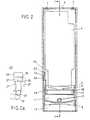
- Figure 2 shows the section li-li of Figure 1;
- FIG. 2a shows a view of the two end positions of the indicator flag in relation to the viewing window in the cover of the soap dispenser according to FIG. 1:
- Figure 3 shows the profile 111-111 of Figure 1 of the rear wall, the cover and the reservoir and
- FIG. 4 shows a plan view of the float arrangement of the display device from FIG. 1.
In den Abbildungen sind gleiche Teile mit gleichen Bezugszeichen versehen.In the figures, the same parts are provided with the same reference symbols.
In der Schnittdarstellung von Figur 1 erkennt man eine Halterung für die Seifenlösungs-Dosiervorrichtung aus einer z. B. an einer Wand befestigbaren Rückwand 1, von deren Enden je eine Halteplatte 1', 3 vorsteht. An der unteren Halteplatte 1', die einstückig mit der Rückwand 1 ausgebildet ist, ist ein Reservoir 4 angebracht, das im einzelnen weiter unten beschrieben wird. An dem Reservoir 4 sind Abstützrippen 4' ausgebildet. An dem Reservoir 4 stützt sich ein Behälter 5 aus durchsichtigem Material für die zu dosierende Seifenlösung ab, der mit einem Hals 5' versehen ist, welcher eine Öffnung 8 bestimmt. Die ganze Anordnung ist von einer Abdeckhaube 6 umgeben, die an Halteelementen 7 an der oberen Halteplatte 3 gehaltert ist und seitlich auf die vorspringende Rückwand 1 aufgeschoben ist (vgl. Fig. 3).In the sectional view of Figure 1 you can see a holder for the soap solution dosing device from a z. B. on a wall attachable
Das auf die untere Halteplatte 1' aufgeschobene und an den Seiten durch die Abdeckhaube 6 abgedeckte Reservoir 4 ist mit einem Befestigungsteil 10 an der Rückwand 1 angeordnet. Ein Boden 9 unterteilt das Reservoir 4 in einen Innenraum 11 und einen Pumpenraum 12. Die beiden Räume 11 und 12 sind durch einen an beiden Enden offenen Zylinder 13, der im Boden 9 eingesetzt ist, miteinander verbunden. In dem der Rückwand 1 abgekehrten Teil des Pumpenraums 12 ist ein Druckknopf 14 gegen die Kraft einer (nicht gezeigten) Rückholfeder zwischen zwei Anschlägen, von denen nur ein Anschlag 15 erkennbar ist, bewegbar. Dieser Druckknopf 14 ist mit einem nicht dargestellten Kolben verbunden, dessen anderes Ende im Zylinder 13 gelagert ist. Die untere Seite des Drucknopfes 14 ist mit einem Ausfluss 14' für die Seifenlösung versehen. Der Druckknopf 14 und der Zylinder 13 bilden Teile einer an sich bekannten Dosiervorrichtung, die hier nicht im einzelnen beschrieben wird.The
Von der Anzeigevorrichtung ist in Figur 1 ein zylindrischer Schwimmerkörper 21 erkennbar, von dem eine Anzeigefahne 22 nach oben und ein Hebel 25' seitlich verlaufen. Der Hebel 25' ist an einem Lager 26 an das Reservoir 4 angelenkt.A
In dem in Figur 2 dargestellten Schnitt tragen die in Figur 1 bereits dargestellten Teile die gleichen Bezugszeichen. Zusätzlich erkennt man in der Darstellung von Figur 2, dass die Anzeigefahne 22 an einer Stirnseite des Schwimmerkörpers 21 angeordnet ist und in einen Raum 23 hineinragt, der zwischen einer Einbuchtung 24 am halsseitigen Ende des Behälters 5 und der Abdeckhaube 6 ausgebildet ist. Die Abdeckhaube 6 ist mit einem Sichtfenster 28 versehen, durch das hindurch die Anzeigefahne 22 sichtbar ist.In the section shown in Figure 2, the parts already shown in Figure 1 have the same reference numerals. In addition, it can be seen in the illustration in FIG. 2 that the
Das in Figur 3 dargestellte Profil der Rückwand 1, des Reservoirs 4 und der Abdeckhaube 6 zeigt den Befestigungsteil 10 und die Abstützrippen 4'. Man erkennt, dass das Reservoir 4 ohne Zwischenraum der Abdeckhaube 6 und der Rückwand 1 befestigt ist.The profile of the
Die Draufsicht von Figur 4 zeigt das Reservoir 4 mit dem Befestigungsteil 10 und die Schwimmeranordnung mit dem Schwimmerkörper 21, von dessen beiden Stirnseiten Hebel 25 und 25' ausgehen, die an Lager 26 an das Reservoir 4 angelenkt sind. Diese Lager 26 sind als Vorsprünge dargestellt, die nahe den Enden der Hebel 25, 25' ausgebildet und in entsprechenden Ausnehmungen in der zugehörigen Wandung des Reservoirs 4 angebracht sind. In diesem Beispiel ist nur der Hebel 25' mit einer Anzeigefahne 22 versehen.The top view of FIG. 4 shows the
Nachfolgend wird die Arbeitsweise der Anzeigevorrichtung anhand der Figuren 1 und 2a erläutert. Man erkennt in Figur 1 einen oberen Flüssigkeitsspiegel 2, der auf der Höhe der Öffnung 8 des Behälters 5 verläuft. Dies ist der normale Betriebszustand des Seifenspenders, der solange besteht, wie der Behälter 5 Seifenlösung enthält. Der Schwimmerkörper 21 befindet sich in der oberen Stellung wie er in Figuren 1 und 2 dargestellt ist. Wie sich im einzelnen aus Figur 2a ergibt, enthält die Anzeigefahne 22 an ihrem von dem Schwimmerkörper 21 abgekehrten Ende zwei Farbfelder 27 und 29. Diese Farbfelder sind unterschiedlich gefärbt: im Ausführungsbeispiel ist das Farbfeld 27 grün und das Farbfeld 29 rot. Der durch das Sichtfenster 28 in der Abdeckhaube 6 in der Stellung der Anzeigefahne 22 gemäss Figur 1 erkennbare Bereich des Farbfeldes 27 ist in Figur 2a punktiert angedeutet und mit 30 bezeichnet. Im gefüllten Betriebszustand des Seifenspenders schwimmt der Schwimmerkörper 21 auf dem oberen Flüssigkeitsspiegel 2, so dass das untere Farbfeld 27 der Anzeige 22 zu dem Sichtfenster 28 in der Abdeckhaube 6 ausgerichtet ist. Die grüne Farbe des Farbfeides 27 zeigt die Betriebsbereitschaft des Seifenspenders an.The mode of operation of the display device is explained below with reference to FIGS. 1 and 2a. One can see in FIG. 1 an
Nach Entleerung des Behälters 5 sinkt während des Betriebes der Flüssigkeitsspiegel stufenweise im Reservoir 4 bis auf einen unteren Flüssigkeitsspiegel ab, der in Figur 1 mit 2' bezeichnet ist. Der Schwimmerkörper 21 und damit die Anzeigefahne 22 folgt dieser Bewegung entlang einer Bewegungsbahn, die kreisbogenartig verläuft. Die Endstellung des Schwimmerkörpers 21 mit der Anzeigefahne 22 entsprechend dem unteren Flüssigkeitsspiegel 2' in Figur 1 ist in Figur 2a in gestrichelten Linien dargestellt. Man erkennt aus dieser Darstellung, dass in dieser Stellung der Anzeigefahne 22 das obere Farbfeld 29, das rot gefärbt ist, zum Sichtfenster 28 der Abdeckhaube 6 ausgerichtet ist und der Bereich 30 des Farbfeldes 29 durch das Sichtfenster 28 hindurch erkennbar ist.After emptying the
Zwischen .den beiden in Figur 2a gezeigten Endstellungen ist durch das Sichtfenster 28 in der Abdeckhaube 6 ein Bereich 30 erkennbar, der Teile von beiden Farbfeldern 27 und 29 erfasst. Somit wird das Wartungspersonal rechtzeitig auf die Entleerung des Behälters 5 aufmerksam gemacht, bevor das Reservoir 4 vollständig leer ist.Between the two end positions shown in FIG. 2a, an
Der den Innenraum 11 des Reservoirs 4 mit dem Pumpenraum 12 des Reservoirs 4 verbindende Zylinder 13 hat einerseits eine Öffnung, die gross genug ist, um einen hinreichenden Durchfluss der Seifenlösung zu gewährleisten. Diesem Zylinder 13 ist ein nicht dargestellter, an sich bekannter durchgebohrter Kolben zugeordnet, der Bestandteil einer Dosiervorrichtung ist, die mit dem Druckknopf 14 verbunden ist. Ein Ausfluss 14' für die Seifenlösung ist im vorderen Teil der unteren Fläche des Druckknopfes 14 angeordnet.The
In einer Weiterbildung des dargestellten Ausführungsbeispieis ist vorgesehen, dass an jeder Stirnseite des Schwimmerkörpers 21 eine Anzeigefahne 22 und entsprechend an jeder Seite der Abdeckhaube 6 ein Sichtfenster 28 ausgebildet ist. Der Füllzustand des Seifenspenders ist dann auf zwei verschiedenen Seiten der Abdeckhaube 6 erkennbar und kann nicht durch bauliche Gegebenheiten oder dergleichen beeinträchtigt werden.In a further development of the exemplary embodiment shown, it is provided that a
In einer weiteren Ausgestaltung kann die Anzeigefahne 22 überhaupt nur mit einem Feld versehen sein, das nach Entleerung des Behälters 5 im Sichtfenster 28 der Abdeckhaube 6 erkennbar wird.In a further embodiment, the
Das Feld oder die Felder brauchen nicht als Farbfelder ausgebildet zu sein, sondern können auch beispielsweise reflektierend, selbstleuchtend. nachleuchtend oder sonst in auffälliger Weise gekennzeichnet sein. Die Anzeigefahne 22 kann sich auch in einem von der Rückwand 1 weiter entfernten Bereich befinden. Der Schwimmerkörper 21 kann auch durch andere Führungsmittel an dem Reservoir 4 geführt sein. Auch kann sich die Anzeigefahne 22 in anderer Richtung erstrecken oder das Feld bzw. die Felder 27, 29 an anderen Teilen der Schwimmeranordnung ausgebildet sein, wobei das, bzw. die Sichtfenster 28 in der Abdeckhaube 6 entsprechend angeordnet werden.The field or fields need not be designed as color fields, but can also be reflective, for example, self-luminous. luminescent or otherwise marked in a conspicuous manner. The
Der Seifenspender könnte auch mit einem fest montierbaren, nachfüllbaren Behälter für die zu dosierende Seifenlösung versehen sein.The soap dispenser could also be provided with a fixed, refillable container for the soap solution to be dosed.
Claims (8)
Priority Applications (1)
| Application Number | Priority Date | Filing Date | Title |
|---|---|---|---|
| AT83810565TATE19936T1 (en) | 1982-12-24 | 1983-12-05 | SOAP DISPENSER WITH A SOAP SOLUTION LEVEL INDICATOR. |
Applications Claiming Priority (2)
| Application Number | Priority Date | Filing Date | Title |
|---|---|---|---|
| CH7544/82 | 1982-12-24 | ||
| CH754482 | 1982-12-24 |
Publications (2)
| Publication Number | Publication Date |
|---|---|
| EP0116812A1 EP0116812A1 (en) | 1984-08-29 |
| EP0116812B1true EP0116812B1 (en) | 1986-05-28 |
Family
ID=4326811
Family Applications (1)
| Application Number | Title | Priority Date | Filing Date |
|---|---|---|---|
| EP83810565AExpiredEP0116812B1 (en) | 1982-12-24 | 1983-12-05 | Soap dispenser with a device indicating the level of a liquid soap |
Country Status (8)
| Country | Link |
|---|---|
| US (1) | US4570823A (en) |
| EP (1) | EP0116812B1 (en) |
| JP (1) | JPS59135037A (en) |
| AT (1) | ATE19936T1 (en) |
| DE (1) | DE3363822D1 (en) |
| HK (1) | HK97989A (en) |
| MY (1) | MY8700932A (en) |
| SG (1) | SG96087G (en) |
Families Citing this family (29)
| Publication number | Priority date | Publication date | Assignee | Title |
|---|---|---|---|---|
| US4850403A (en)* | 1988-04-25 | 1989-07-25 | Wiese Patrick C | Funnel with indicator showing filled condition of serviced container |
| US5615801A (en)* | 1990-06-06 | 1997-04-01 | The Coca-Cola Company | Juice concentrate package for postmix dispenser |
| US5842603A (en)* | 1990-06-06 | 1998-12-01 | The Coca-Cola Company | Postmix juice dispenser |
| US5261557A (en)* | 1992-10-13 | 1993-11-16 | Scott Paper Company | Decorative window for paper and soap product dispensers |
| US5370277A (en)* | 1993-07-01 | 1994-12-06 | Wallis; Stephen R. | Pour spout container |
| US6089086A (en)* | 1997-08-26 | 2000-07-18 | Rochester Gauges, Inc. | Liquid level gauge |
| EP1118301A1 (en)* | 2000-01-19 | 2001-07-25 | Cws International Ag | Soap solution dispensing device in a dispenser |
| EP1118300A1 (en)* | 2000-01-19 | 2001-07-25 | Cws International Ag | Soap dispenser |
| US7066356B2 (en)* | 2002-08-15 | 2006-06-27 | Ecolab Inc. | Foam soap dispenser for push operation |
| NL1029155C2 (en)* | 2004-10-19 | 2006-04-20 | Sara Lee De Nv | System and method for preparing a drink suitable for consumption. |
| US8500818B2 (en)* | 2006-09-29 | 2013-08-06 | Biomet Manufacturing, Llc | Knee prosthesis assembly with ligament link |
| GB2467661B (en) | 2007-09-20 | 2013-02-13 | Bradley Fixtures Corp | Lavatory system |
| US20100094352A1 (en)* | 2008-10-10 | 2010-04-15 | Andrew Iott | Bone screw |
| AT508090B1 (en) | 2009-04-09 | 2011-05-15 | Hagleitner Hans Georg | DISTRIBUTOR FOR FLOWABLE MEDIUM |
| US8397782B2 (en)* | 2009-10-01 | 2013-03-19 | Pitney Bowes Inc. | Mailing machine fluid level indicator |
| WO2011044247A1 (en) | 2009-10-07 | 2011-04-14 | Bradley Fixtures Corporation | Lavatory system with hand dryer |
| US8714413B2 (en) | 2010-03-10 | 2014-05-06 | Mary Elizabeth Coleman Fuqua | Mouthwash dispenser |
| US20110220683A1 (en)* | 2010-03-10 | 2011-09-15 | Mary Elizabeth Coleman Fuqua | Mouthwash Dispenser |
| DE202010006216U1 (en) | 2010-04-29 | 2010-07-01 | Hagleitner, Hans Georg | donor |
| US9267736B2 (en) | 2011-04-18 | 2016-02-23 | Bradley Fixtures Corporation | Hand dryer with point of ingress dependent air delay and filter sensor |
| US9170148B2 (en)* | 2011-04-18 | 2015-10-27 | Bradley Fixtures Corporation | Soap dispenser having fluid level sensor |
| MX352853B (en) | 2012-03-21 | 2017-12-13 | Bradley Fixtures Corp | Basin and hand drying system. |
| US10100501B2 (en) | 2012-08-24 | 2018-10-16 | Bradley Fixtures Corporation | Multi-purpose hand washing station |
| US9586728B2 (en) | 2012-10-25 | 2017-03-07 | Sca Hygiene Products Ab | Dispensing system with the means for detecting liquid level and a collapsible container for such a system |
| US9505015B2 (en) | 2013-05-21 | 2016-11-29 | S. C. Johnson & Son, Inc. | Trigger sprayer with bottle filling conduit |
| EP2873357A1 (en)* | 2013-11-15 | 2015-05-20 | Hygiene Vision Europe BVBA | Dispenser |
| WO2015120377A1 (en)* | 2014-02-07 | 2015-08-13 | Gojo Industries, Inc. | Dispenser and container |
| US10041236B2 (en) | 2016-06-08 | 2018-08-07 | Bradley Corporation | Multi-function fixture for a lavatory system |
| US11015329B2 (en) | 2016-06-08 | 2021-05-25 | Bradley Corporation | Lavatory drain system |
Family Cites Families (13)
| Publication number | Priority date | Publication date | Assignee | Title |
|---|---|---|---|---|
| US532981A (en)* | 1895-01-22 | John c | ||
| US1430189A (en)* | 1919-09-15 | 1922-09-26 | Rinaldi Joseph | Liquid-vending machine |
| US1751847A (en)* | 1928-06-19 | 1930-03-25 | John J Wilt | Radiator gauge |
| US2042928A (en)* | 1935-06-19 | 1936-06-02 | Costa Leo L Da | Liquid dispensing means |
| DE899155C (en)* | 1951-09-27 | 1953-12-07 | Hans Metzger | Device for recognizing the liquid level when filling the liquid in tanks or the like, in particular of motor vehicles |
| US2859724A (en)* | 1956-03-23 | 1958-11-11 | Gen Electric | Gauge dial |
| US3187954A (en)* | 1961-11-03 | 1965-06-08 | Feinson | Soap dispensers |
| US3371535A (en)* | 1966-01-07 | 1968-03-05 | Gen Electric | Liquid level indicator for dispenser in dishwasher door |
| DK144053C (en)* | 1971-12-01 | 1982-05-03 | E Schumm | Soap |
| FR2339382A1 (en)* | 1976-01-27 | 1977-08-26 | Jacot Daniel | Liquid soap dispenser with two supply reservoirs - has replaceable top reservoir and recoil spring discharge plunger with two non return valves |
| CH644002A5 (en)* | 1979-07-17 | 1984-07-13 | Europtool Trust | SOAP SOLUTION DOSING DEVICE. |
| DE3112151A1 (en)* | 1980-04-02 | 1982-03-18 | Appor Ltd., Milford, Derby | DISPENSER OR DISPENSER |
| US4391309A (en)* | 1981-04-16 | 1983-07-05 | Steiner Corporation | Soap dispensing system |
- 1983
- 1983-12-05DEDE8383810565Tpatent/DE3363822D1/ennot_activeExpired
- 1983-12-05EPEP83810565Apatent/EP0116812B1/ennot_activeExpired
- 1983-12-05ATAT83810565Tpatent/ATE19936T1/ennot_activeIP Right Cessation
- 1983-12-19USUS06/563,045patent/US4570823A/ennot_activeExpired - Fee Related
- 1983-12-23JPJP58242331Apatent/JPS59135037A/enactiveGranted
- 1987
- 1987-10-30SGSG960/87Apatent/SG96087G/enunknown
- 1987-12-30MYMY932/87Apatent/MY8700932A/enunknown
- 1989
- 1989-12-07HKHK979/89Apatent/HK97989A/ennot_activeIP Right Cessation
Also Published As
| Publication number | Publication date |
|---|---|
| US4570823A (en) | 1986-02-18 |
| DE3363822D1 (en) | 1986-07-03 |
| JPS59135037A (en) | 1984-08-03 |
| JPH0350528B2 (en) | 1991-08-02 |
| HK97989A (en) | 1989-12-15 |
| SG96087G (en) | 1988-05-06 |
| EP0116812A1 (en) | 1984-08-29 |
| ATE19936T1 (en) | 1986-06-15 |
| MY8700932A (en) | 1987-12-31 |
Similar Documents
| Publication | Publication Date | Title |
|---|---|---|
| EP0116812B1 (en) | Soap dispenser with a device indicating the level of a liquid soap | |
| DE2544817C3 (en) | Liquid soap dispenser | |
| DE4432786A1 (en) | Liquid pump container | |
| EP0853458B1 (en) | Metering dispenser for liquids | |
| DE60123084T2 (en) | Flexible container for use in a liquid dispenser | |
| DE1628593A1 (en) | Dosing device for the automatic addition of liquid detergents or cleaning agents in dishwashers or the like. | |
| DE68923166T2 (en) | Testing device for the ink supply in writing instruments. | |
| EP1553857B1 (en) | Cleaning appliance for the shaving head of a razor and container therefor | |
| EP0114569B1 (en) | Method for the supply of a device for dispensing measured quantities of a liquid soap, and device for carrying out the method | |
| DE2736291C2 (en) | Dosing device for adding a measured amount of liquid to the washing area, in particular a dishwasher | |
| EP0114026B1 (en) | Replaceable container for a liquid-soap dispenser | |
| DE2506383A1 (en) | OVERFLOW PROTECTION AND LEVEL CONTROL OF A CONTAINER | |
| DE3738792A1 (en) | Method for indicating the filling quantity of filling goods in a container and indicating device for the filling quantity | |
| DE8019235U1 (en) | SOAP SOLUTION DOSING DEVICE | |
| DE2832364A1 (en) | Mounting for transparent fluid reservoir - is on pull=out fitting in dashboard and has visible front scale | |
| DE2005612A1 (en) | Iron with a container for water for steam or spray purposes | |
| DE3242761A1 (en) | Metering device | |
| AT200949B (en) | Liquor dispenser | |
| DE2365528A1 (en) | Disposable refill bottle for liquid soap dispensers - has neckless foil-covered top opening to prevent surreptitious refilling of refill | |
| DE2114554A1 (en) | Water dispenser | |
| DE1155665B (en) | Advertising device | |
| AT138593B (en) | Automatic machine for the dosed dispensing of pasty substances. | |
| DE9011348U1 (en) | Level indicator, especially for beverage production equipment | |
| DE3024409A1 (en) | Liquid soap dispenser with dosing mechanism - has refillable or replaceable supply container mounted on pull-out shelf inside casing | |
| DE440476C (en) | Locking device for the valves of fuel pumps |
Legal Events
| Date | Code | Title | Description |
|---|---|---|---|
| PUAI | Public reference made under article 153(3) epc to a published international application that has entered the european phase | Free format text:ORIGINAL CODE: 0009012 | |
| 17P | Request for examination filed | Effective date:19840616 | |
| AK | Designated contracting states | Designated state(s):AT BE CH DE FR GB IT LI LU NL SE | |
| ITF | It: translation for a ep patent filed | ||
| GRAA | (expected) grant | Free format text:ORIGINAL CODE: 0009210 | |
| AK | Designated contracting states | Kind code of ref document:B1 Designated state(s):AT BE CH DE FR GB IT LI LU NL SE | |
| REF | Corresponds to: | Ref document number:19936 Country of ref document:AT Date of ref document:19860615 Kind code of ref document:T | |
| REF | Corresponds to: | Ref document number:3363822 Country of ref document:DE Date of ref document:19860703 | |
| ET | Fr: translation filed | ||
| PLBE | No opposition filed within time limit | Free format text:ORIGINAL CODE: 0009261 | |
| STAA | Information on the status of an ep patent application or granted ep patent | Free format text:STATUS: NO OPPOSITION FILED WITHIN TIME LIMIT | |
| 26N | No opposition filed | ||
| ITTA | It: last paid annual fee | ||
| EPTA | Lu: last paid annual fee | ||
| EAL | Se: european patent in force in sweden | Ref document number:83810565.8 | |
| PGFP | Annual fee paid to national office [announced via postgrant information from national office to epo] | Ref country code:SE Payment date:19961128 Year of fee payment:14 | |
| PGFP | Annual fee paid to national office [announced via postgrant information from national office to epo] | Ref country code:LU Payment date:19961201 Year of fee payment:14 | |
| PGFP | Annual fee paid to national office [announced via postgrant information from national office to epo] | Ref country code:BE Payment date:19961219 Year of fee payment:14 | |
| PGFP | Annual fee paid to national office [announced via postgrant information from national office to epo] | Ref country code:NL Payment date:19961231 Year of fee payment:14 | |
| PG25 | Lapsed in a contracting state [announced via postgrant information from national office to epo] | Ref country code:LU Free format text:LAPSE BECAUSE OF NON-PAYMENT OF DUE FEES Effective date:19971205 | |
| PG25 | Lapsed in a contracting state [announced via postgrant information from national office to epo] | Ref country code:SE Free format text:LAPSE BECAUSE OF NON-PAYMENT OF DUE FEES Effective date:19971206 | |
| PG25 | Lapsed in a contracting state [announced via postgrant information from national office to epo] | Ref country code:BE Free format text:LAPSE BECAUSE OF NON-PAYMENT OF DUE FEES Effective date:19971231 | |
| BERE | Be: lapsed | Owner name:CWS A.G. Effective date:19971231 | |
| PG25 | Lapsed in a contracting state [announced via postgrant information from national office to epo] | Ref country code:NL Free format text:LAPSE BECAUSE OF NON-PAYMENT OF DUE FEES Effective date:19980701 | |
| NLV4 | Nl: lapsed or anulled due to non-payment of the annual fee | Effective date:19980701 | |
| EUG | Se: european patent has lapsed | Ref document number:83810565.8 | |
| PGFP | Annual fee paid to national office [announced via postgrant information from national office to epo] | Ref country code:GB Payment date:19991201 Year of fee payment:17 | |
| PGFP | Annual fee paid to national office [announced via postgrant information from national office to epo] | Ref country code:AT Payment date:20001122 Year of fee payment:18 | |
| PG25 | Lapsed in a contracting state [announced via postgrant information from national office to epo] | Ref country code:GB Free format text:LAPSE BECAUSE OF NON-PAYMENT OF DUE FEES Effective date:20001205 | |
| PGFP | Annual fee paid to national office [announced via postgrant information from national office to epo] | Ref country code:FR Payment date:20001212 Year of fee payment:18 | |
| PGFP | Annual fee paid to national office [announced via postgrant information from national office to epo] | Ref country code:DE Payment date:20001229 Year of fee payment:18 | |
| PGFP | Annual fee paid to national office [announced via postgrant information from national office to epo] | Ref country code:CH Payment date:20010122 Year of fee payment:18 | |
| GBPC | Gb: european patent ceased through non-payment of renewal fee | Effective date:20001205 | |
| PG25 | Lapsed in a contracting state [announced via postgrant information from national office to epo] | Ref country code:AT Free format text:LAPSE BECAUSE OF NON-PAYMENT OF DUE FEES Effective date:20011205 | |
| PG25 | Lapsed in a contracting state [announced via postgrant information from national office to epo] | Ref country code:LI Free format text:LAPSE BECAUSE OF NON-PAYMENT OF DUE FEES Effective date:20011231 Ref country code:CH Free format text:LAPSE BECAUSE OF NON-PAYMENT OF DUE FEES Effective date:20011231 | |
| PG25 | Lapsed in a contracting state [announced via postgrant information from national office to epo] | Ref country code:DE Free format text:LAPSE BECAUSE OF NON-PAYMENT OF DUE FEES Effective date:20020702 | |
| REG | Reference to a national code | Ref country code:CH Ref legal event code:PL | |
| PG25 | Lapsed in a contracting state [announced via postgrant information from national office to epo] | Ref country code:FR Free format text:LAPSE BECAUSE OF NON-PAYMENT OF DUE FEES Effective date:20020830 | |
| REG | Reference to a national code | Ref country code:FR Ref legal event code:ST |