EP0113662B1 - Cellular mobile radio service telephone system - Google Patents
Cellular mobile radio service telephone systemDownload PDFInfo
- Publication number
- EP0113662B1 EP0113662B1EP84100056AEP84100056AEP0113662B1EP 0113662 B1EP0113662 B1EP 0113662B1EP 84100056 AEP84100056 AEP 84100056AEP 84100056 AEP84100056 AEP 84100056AEP 0113662 B1EP0113662 B1EP 0113662B1
- Authority
- EP
- European Patent Office
- Prior art keywords
- control
- coupled
- ncs
- statistical
- port
- Prior art date
- Legal status (The legal status is an assumption and is not a legal conclusion. Google has not performed a legal analysis and makes no representation as to the accuracy of the status listed.)
- Expired
Links
- 230000001413cellular effectEffects0.000titleclaimsdescription10
- 239000011159matrix materialSubstances0.000claimsdescription24
- 230000005540biological transmissionEffects0.000claimsdescription20
- 230000005236sound signalEffects0.000claimsdescription3
- 230000008878couplingEffects0.000claimsdescription2
- 238000010168coupling processMethods0.000claimsdescription2
- 238000005859coupling reactionMethods0.000claimsdescription2
- 238000004891communicationMethods0.000description11
- 230000011664signalingEffects0.000description10
- 238000000034methodMethods0.000description7
- 238000012423maintenanceMethods0.000description5
- 230000002457bidirectional effectEffects0.000description4
- 238000012545processingMethods0.000description4
- 238000012360testing methodMethods0.000description3
- 238000013519translationMethods0.000description3
- 230000003750conditioning effectEffects0.000description2
- 230000006870functionEffects0.000description2
- 230000002093peripheral effectEffects0.000description2
- 230000005855radiationEffects0.000description2
- 230000000295complement effectEffects0.000description1
- 238000010586diagramMethods0.000description1
- 230000004044responseEffects0.000description1
- 230000001360synchronised effectEffects0.000description1
Images


Classifications
- H—ELECTRICITY
- H04—ELECTRIC COMMUNICATION TECHNIQUE
- H04W—WIRELESS COMMUNICATION NETWORKS
- H04W84/00—Network topologies
- H04W84/02—Hierarchically pre-organised networks, e.g. paging networks, cellular networks, WLAN [Wireless Local Area Network] or WLL [Wireless Local Loop]
- H04W84/04—Large scale networks; Deep hierarchical networks
- H04W84/042—Public Land Mobile systems, e.g. cellular systems
- Y—GENERAL TAGGING OF NEW TECHNOLOGICAL DEVELOPMENTS; GENERAL TAGGING OF CROSS-SECTIONAL TECHNOLOGIES SPANNING OVER SEVERAL SECTIONS OF THE IPC; TECHNICAL SUBJECTS COVERED BY FORMER USPC CROSS-REFERENCE ART COLLECTIONS [XRACs] AND DIGESTS
- Y02—TECHNOLOGIES OR APPLICATIONS FOR MITIGATION OR ADAPTATION AGAINST CLIMATE CHANGE
- Y02D—CLIMATE CHANGE MITIGATION TECHNOLOGIES IN INFORMATION AND COMMUNICATION TECHNOLOGIES [ICT], I.E. INFORMATION AND COMMUNICATION TECHNOLOGIES AIMING AT THE REDUCTION OF THEIR OWN ENERGY USE
- Y02D30/00—Reducing energy consumption in communication networks
- Y02D30/70—Reducing energy consumption in communication networks in wireless communication networks
Definitions
- This inventionpertains to an improved type of mobile telephone system, in general, and to an improved cellular mobile radio telephone system, in particular.
- CMRSCellular Mobile Radio Service
- the radiotelephone unitsutilize radio frequency to communicate with low power, limited radiation base transceivers in a cellular pattern making it necessary for the system to locate each mobile unit and follow it enroute by "handing off" in-progress calls between cells.
- the low power, limited radiation elements of CMRS systemsallow a unique frequency distribution and reuse scheme to provide sufficient channels to serve any number of subscribers (i.e. 100,000).
- the mobile radiosare intelligent units; that is, they contain a microprocessor equivalent logic element. They store certain permanent information (i.e. unit manufacturer's serial number), semi-permanent information (i.e. registration memory), temporary memory containing individual call data and timers, etc.
- permanent informationi.e. unit manufacturer's serial number
- semi-permanent informationi.e. registration memory
- temporary memorycontaining individual call data and timers, etc.
- each unitcan access 666 radio channels but must manually or automatically select either an upper band of 333 or a lower band (Current FCC rules allocate the upper band to a non-wire line RCC and the lower band to a telco owned RCC).
- the base radio "stations"are located in a pattern of "cells" of from about 1 mile to up to 10 miles across which form a patchwork coverage of the desired area.
- Each cell radiooperates with several assigned channels selected so that they do not interfere with channels of nearby cells. Due to the restricted power and range of cell radio transmitters, each set of cell frequencies may be reused in a cell only a few miles away.
- CMRSAdvanced Mobile Phone Service
- AMPSAdvanced Mobile Phone Service
- the telephone system for providing communications between mobile radiotelephones, portable radiotelephones and land-line telephonesincludes a land-line telephone system including a land-line switching network for providing communication paths for land-line telephones, and a mobile radiotelephone system for providing communication paths for mobile and portable radiotelephones.
- the mobile radiotelephone systemincludes a digital switching network, base stations, and PCM analog-to-digital (A/D) and digital-to-analog (D/A) converters interposed between the base ⁇ Ioti g n ⁇ and the digital switching network and between the land-line switching network and the digital switching network.
- Analog portsare interfaced by the PCM A/D and D/A converters to incoming and outgoing serial bit streams coded according to pulse-code-modulation (PCM) techniques standardized for telecommunications systems by the International Cord and Telephone Consultative Committee (CCITT).
- PCMpulse-code-modulation
- CITTInternational Committee
- the digital switching networkreceives the incoming serial PCM bit streams and provides the outgoing serial PCM bit streams so that telephone calls are automatically routed between the calling and called parties in the telephone system.
- Supervisory signallingis detected from the incoming serial PCM bit streams and processed by a signal processing unit to determine an ordering of time slots for the PCM channels for controlling the interchange of PCM channels from the incoming serial PCM bit streams to the outgoing PCM channels corresponding to the incoming supervisory signalling from incoming PCM channels is adapted to a pre-established format recognized by the corresponding outgoing PCM channels and multiplexed into the respective outgoing serial PCM bit streams.
- a cellular mobile radio systemhaving "switched-through control". More specifically, the switching matrix used for switching of the signals representing the audio portion of telephone calls is also used to selectively switch the various control signals associated with processing of telephone calls.
- control signals between cell site transceivers and the network control systemare switched through the switching matrix and share the standard transmission facilities used for the audio aspect of telephone calls.
- multiple NCS'smay be used to expand the size of the CMRS system by exchanging control information via paths established through the respective switching matrices and the standard transmission facilities interconnecting the NCS's.
- a CMRS systemmay be provided with a remote switch group (RSG) arrangement having its own switching matrix and wherein the RSG arrangements operate under its own microprocessor control with sufficient intelligence to switch port-to-port traffic and perform routine tasks under NCS direction via the NCS switching matrix standard transmission facilities and the RSG switching matrix.
- RSGremote switch group
- a high degree of reliabilitymay be provided by the use of individually redundant cells coupled to a NCS switching matrix which in turn couples to a common pool of control elements.
- control signals for a plurality of transceiversare statistically multiplied together to form a concentrated byte interleaved data stream.
- a plurality of concentrated data streamsare reformatted in packetized form into a more highly concentrated data stream which is presented to the NCS central processor complex.
- the CMRS system of Fig. 1illustrates an arrangement having 7 cells each having voice and data connections to a network control system ((NCS).
- the NCSis in turn connected to the telephone network.
- Each celluses one or more of 21 channels as set-up channels to broadcast continuously certain routine or overhead information which permits the mobiles to select the nearest cell, identify the system, etc.
- the CMRS systemcontinuously transmits digital data on each cell set-up channel including such information as the CMRS system identification, overload control ("line load” control), synchronizing bits, busy-idle status of reverse signaling channel and signaling channel numbers used in this location.
- HMUHome Mobile Unit
- the systemwould try to page it by sending out the car directory number on paging (set-up) channels.
- the NCScan return such an indication to the calling subscriber in the form of an announcement. (If the called mobile unit is turned on and answers the page, the mobile will be "rung" and the callerwill receive ringbacktone indicating that the mobile is in the area and turned on).
- the mobile unitfirst turns on his radiotelephone, it first scans all set-up channels. The unit would verify that is was in its home area and the paging (or set-up) channels and voice channels used in this complex would be identified to the mobile unit.
- the mobile unitwould then scan the identified set-up channel and select and tune to the strongest one, presumably the nearest cell transmitter. "Busy-idle" bits inform the mobile unit the status of the reverse (mobile to base) signaling channel to prevent simultaneous seizure by more than one mobile unit. (There are also other handshake and timing checks to guard against "collisions”.)
- the mobile unitnow automatically "reports in” to the system and sends its unit serial number, its assigned telephone number (7 or 10 digits), its power level, etc. and turns off it transmitter, continuing to monitor the selected set-up channel for a page.
- the NCS"registers" the mobile unit as either a home or foreign unit. Depending upon system procedures, the registration could verify that service has not been discontinued or is not on a "hot list” relating to unauthorized use or stolen units.
- the NCSdirects the paging (7 digit number) to be sent on the appropriate paging channels.
- the mobilereceives the page and detects that it coincides with its assigned telephone number. it acknowledges on a selected set-up channel by sending back its identification number.
- the NCSselects a voice channel and advises the mobile to switch to that channel, abandoning the set-up channel.
- the mobileacknowledges that he is now tuned to the selected voice channel by an in-band SAT (supervisory) tone.
- the NCSdirects the base RF equipment to send an alerting data burst over the voice channel and the mobile begins the audible alert (ringing).
- the mobilereturns an out of band signaling tone acknowledging that it is in a ringing process and the NCS returns ringback to the calling party.
- the signaling toneis removed and the call cut through.
- the mobilegoes "off hook” and scans and selects the strongest set-up channel.
- the mobilesends identification and the dialed digits to the NCS.
- the mobile unitthen waits for a voice channel assignment and, by supervisory and signaling tones associated with the assigned channel, provides the neessary answer supervision, disconnect, etc.
- the set-up channelsare used only very briefly during the identification, location and voice channel assignment process. Since this is a big "party line” or common channel, occupancy must be limited.
- CMRSCMRS CMRS CMRS CMRS CMRS CMRS CMRS CMRS CMRS CMRS CMRS CMRS CMRS CMRS CMRS CMRS CMRS CMRS CMRS CMRS CMRS CMRS CMRS CMRS CMRS CMRS CMRS CMRS CMRS CMRS CMRS CMRS CMRS CMRS CMRS CMRS .
- the NCSdecides when a "hand-off" to another cell is advisable based upon relative signal strength, next cell congestion, etc.
- the NCSenables the new cell and selects a new channel.
- a signal to switch to a new channelis sent to the mobile over the current serving channel by means of a very short digital burst which is not detectable by the listener.
- the mobilesends a disconnect signal tone, turns off its transmitter, re-tunes to the new channel and sends supervisory tone.
- the NCSrecognizes the successful hand-off and
- the mobileis a "roamer” from another CMRS system (though perhaps serving the same area), it will be designated a Foreign Mobile Unit (FMU) in this area. Operation is almost identical except that local calls from the FMU are probably billable and must be recorded with calling details.
- FMUForeign Mobile Unit
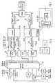
- the block diagram of Fig. 2illustrates the NCS and one cell site of the system of Fig. 1 in greater detail.
- the NCS equipmentincludes the commercially available ITT System 1210 hardware and software.
- the basic configuration shown in Fig. 2includes the ITT System 1210 processor as network control; direct memory access (DMA) equipment; switch groups; a line switch to accomodate service circuits such as DTMFR, MFR conference circuits, line interface (cc) and operator interface (OPI); various I/0 peripherals such as TTY, magnetic tape (MT) and terminals (CRT); trunks; and a system test frame, tone and recorded announcement source, which are not shown in Fig. 1.
- DMAdirect memory access
- switch groupsswitches
- a line switch to accomodate service circuitssuch as DTMFR, MFR conference circuits, line interface (cc) and operator interface (OPI)
- various I/0 peripheralssuch as TTY, magnetic tape (MT) and terminals (CRT); trunks
- the NCSfurther includes a pool of control concentrators coupled between the switch group matrix and the DMA via channel units, modems if necessary, and signal conditioning circuits.
- the NCSis coupled to the cell site via transmission facilities which in the example shown are TI spans.
- the cell siteincludes a plurality of specialized use transceivers including set-up radio transceiver, data channel transceivers, voice channel transceivers, locating radio receivers, paging transmitters, and base radio test equipment.
- each of the trnans- ceivers, receivers or transmittersmay be of type as described in the aforementioned Bell System Technical Journal reference or may be of any other types including types having microprocessor control.
- Each transceiver, receiver, transmitterhas bidirectional control ports for the exchange of control information with the NCS.
- the voice channel transceivers and the base radio test equipmenthave a bidirectional audio signal port; the data channel transceiver has bidirectional data ports.
- the audio signal portsare coupled via a 4-wire voice frequency facility to channel units contained in a channel bank which is in turn coupled to the TI span and thus to the switch matrix in the NCS.
- Each bidirectional control portis duplicated and is coupled to the statistical multiplexers A and B.
- the statistical multiplexersare in turn coupled to channel units in the channel banks which in turn are coupled to -the TI span and thus to switch matrix in the NCS. It should be noted that redundancy is provided for reliability purposes.
- the statistical multiplexers shown in Fig. 2 and also in the other figures to be described belowmay be of the commerically available types described by Harry J. Hindin in “controlling data communications: statistical multiplexer move in",Electronics, July 28,1981, p. 141-148 and by J.H. Scharen-Guivel and A.A. Carlson in “A buyers guide to todays versatile statistical multiplexers", Data Communications, March, 1982, pp. 97-126.
- a statistical multiplexeris utilized to multiplex a number of terminals to a data link.
- Conventional time division multiplexersof either the bit-or the character-interleaving type assign dedicated time slots to each terminal. With statistical multiplexing the available bandwidth of the trunk is allocated dynamically.
- the statistical multiplexeralso performs demultiplexing operations for coupling information from the data link to the terminals by using the inverse of the process described above.
- the control arrangement of Fig. 6illustrates the NCS (Fig. 5) coupled via analog transmission facility (Fig. 3) to one cell and coupled via digital transmission facility (Fig. 4) to another cell.
- each of the cellsis shown as having three voice channel transceivers 31, 32, 33 and one set up transceiver 34.
- Each voice channel transceiverhas a pair of duplicated control ports control A, control B, respectively coupled to a pair of statistical multiplexers 35, 36.
- the data link side of each statistical multiplexer 35, 36utilizes signals that are compatible to one or more of RS 232/422, 423 signaling classes.
- a standard commercially available modem 37is used to convert the signals between the RS 232/422, 423 signaling classes to inband audio tones on an analog transmission facility 38 which is terminated at the NCS via a channel unit contained in channel bank 51.
- the data link side of the statistical multiplexer 35, 36are terminated on commercially available data type channel units in channel banks 41, 42 which are coupled to the digital transmission facility 43 which is terminated at the NCS.
- each cellincludes the redundant pairs of statistical mulitplexers 35, 36.
- N redundant pairsthere are 2N appearances at the left side of the digital matrix as shown in Fig. 6.
- a plurality of channel banks 54are coupled to the terminals at the right side of the digital matrix 52.
- the channel banksinclude data channel units corresponding to the data channel units utilized in the channel banks of Fig. 4 and voice units connected to modems 55 as in Fig. 3.
- the data channel units and modems 55are coupled to ports on a plurality of control concentrators 56 which are in turn coupled to the direct memory access DMA of the central processing unit CPU.
- the communications from a plurality of transceiversis placed on the facility toward the control concentrators in a byte interleaved basis by the statistical multiplexers. Communications from a plurality of statistical multiplexers are byte deleaved and packetized by the control concentrator and serially presented to the DMA via signal conditioning circuits 59.
- the control concentrators 56each serve to reformat and multiplex the communications from a plurality of statistical multiplexers thereby providing another level of multiplexing and concentration of control.
- Each control concentrator 56 shown in greater detail in Fig. 7includes a microprocessor 71 having I/O ports, some of which are coupled to the statistical multiplexers via the matrix and one or a few of which are connected to the DMA.
- a random access memory 72is coupled to the microprocessor 71 as are various peripherals such as a disk unit and a tape unit.
- the memory 72is a 512K bytes of 32 byte memory.
- the number of control concentrators required for a system having N pairs of statistical multiplexersis M+X where X is the number of spare units required to achieve the desired availability.
- Fig. 8illustrates another advantageous configuration of a CMRS system wherein portions of the switching matrix are remoted from the NCS.
- This Remote Switch Group (RSG) arrangementoperates under its own microprocessor control with sufficient intelligence to switch port-to-port traffic and perform routine tasks under host NCS direction.
- the RSGis a remote (from NCS) switching node within the cellular network, and consists in its most basic configuration of two or more standard ITT 1210 switch groups, a digital tone supply, a Stratum III synchronizable clock, and digital or analog trunks as required (see Fig. 10).
- Service circuits (MFR, conference circuits, etc.) and recorded announcement sourcesreside in the host NCS and are assigned dedicated channels in the NSC-to-RSG link route. Service circuits and announcement machines may be added in the RSG when its size and common traffic interest with the NCS make this desirable.
- the synchronizable clockis required to keep the digital RSG matrix synchronized with the NCS and digital links.
- Two of the RSG switch groupsare equipped with special interfaces to the digital tone supply (TAG) and synch clock for maintenance and alarm control access by the NCS system controller.
- TAGdigital tone supply
- synch clockfor maintenance and alarm control access by the NCS system controller.
- the NCS controller data structureis arranged to provide separate translation domains for each RSG. Thus allows individual routing patters for a given called number that are unique to that translation domain. Multiple translation domains per RSG (or NCS) can also be assigned.
- the linksconsist of standard TI span ones (or TI compatible facilities).
- Digital channel banks with individual channel Drop/Insert ports at each endare used for control communication between the NCS system controller and the RSG switch group controllers.
- Two channels per remote switch group controller(on separate TI lines for reliability) are used, and the number of channels dropped/inserted thus depends on the number of individual switch groups in the RSG.
- the switched through control concept which was applied to the arrangements of Figs. 1-7can further advantageously be used for the arrangement of Fig. 8 as shown in Fig. 10.
- the control between the NCS and individual RSG'sis accomplished by establishing a path from the DMA of the NCS through the NCS's matrix over transmission facility to the RSG through its matrix to the switch group (SWG) control of the RSG. Two channels per RSG controller are used for reliability.
- a large cellular geographic areamay be served by multiple NCS's each of which is remote from the others as shown in Fig. 11.
- the switched through control conceptmay still further advantageously be applied to such an arrangement as shown in Fig. 12 wherein a control path may be established between the two NCS's X, Y by establishing a path through the matrix of NCS X, over transmission facility to the other NCS, Y through its matrix and control concentrator.
Landscapes
- Engineering & Computer Science (AREA)
- Computer Networks & Wireless Communication (AREA)
- Signal Processing (AREA)
- Mobile Radio Communication Systems (AREA)
- Use Of Switch Circuits For Exchanges And Methods Of Control Of Multiplex Exchanges (AREA)
Description
- This invention pertains to an improved type of mobile telephone system, in general, and to an improved cellular mobile radio telephone system, in particular.
- Cellular Mobile Radio Service (CMRS) is a fully automatic radiotelephone service for use by mobile, portable, or stationary units specifically designed with sophisticated digital controls and logic. The radiotelephone units utilize radio frequency to communicate with low power, limited radiation base transceivers in a cellular pattern making it necessary for the system to locate each mobile unit and follow it enroute by "handing off" in-progress calls between cells. The low power, limited radiation elements of CMRS systems allow a unique frequency distribution and reuse scheme to provide sufficient channels to serve any number of subscribers (i.e. 100,000).
- The mobile radios are intelligent units; that is, they contain a microprocessor equivalent logic element. They store certain permanent information (i.e. unit manufacturer's serial number), semi-permanent information (i.e. registration memory), temporary memory containing individual call data and timers, etc. In the United States, as a result of FCC regulations, each unit can access 666 radio channels but must manually or automatically select either an upper band of 333 or a lower band (Current FCC rules allocate the upper band to a non-wire line RCC and the lower band to a telco owned RCC).
- The base radio "stations" are located in a pattern of "cells" of from about 1 mile to up to 10 miles across which form a patchwork coverage of the desired area. Each cell radio operates with several assigned channels selected so that they do not interfere with channels of nearby cells. Due to the restricted power and range of cell radio transmitters, each set of cell frequencies may be reused in a cell only a few miles away.
- One CMRS system called the "Advanced Mobile Phone Service" (AMPS) system is described in great detail in "The Bell System Technical Journal," January, 1979, Vol. 58, No. 1, pages 1-269. In the AMPS system control of the various transceivers at a cell site is via dedicated wires to a central processor.
- From EP-Al-0 003 633 there is known a radiotelephone communications system. The telephone system for providing communications between mobile radiotelephones, portable radiotelephones and land-line telephones, according to EP-Al-0 003 633, includes a land-line telephone system including a land-line switching network for providing communication paths for land-line telephones, and a mobile radiotelephone system for providing communication paths for mobile and portable radiotelephones. The mobile radiotelephone system includes a digital switching network, base stations, and PCM analog-to-digital (A/D) and digital-to-analog (D/A) converters interposed between the base§Iotign§ and the digital switching network and between the land-line switching network and the digital switching network. Analog ports are interfaced by the PCM A/D and D/A converters to incoming and outgoing serial bit streams coded according to pulse-code-modulation (PCM) techniques standardized for telecommunications systems by the International Telegraph and Telephone Consultative Committee (CCITT). The digital switching network receives the incoming serial PCM bit streams and provides the outgoing serial PCM bit streams so that telephone calls are automatically routed between the calling and called parties in the telephone system. Supervisory signalling is detected from the incoming serial PCM bit streams and processed by a signal processing unit to determine an ordering of time slots for the PCM channels for controlling the interchange of PCM channels from the incoming serial PCM bit streams to the outgoing PCM channels corresponding to the incoming supervisory signalling from incoming PCM channels is adapted to a pre-established format recognized by the corresponding outgoing PCM channels and multiplexed into the respective outgoing serial PCM bit streams.
- In accordance with the principles of the invention, a cellular mobile radio system is provided having "switched-through control". More specifically, the switching matrix used for switching of the signals representing the audio portion of telephone calls is also used to selectively switch the various control signals associated with processing of telephone calls.
- Even more specifically in accordance with the invention, control signals between cell site transceivers and the network control system (NCS) are switched through the switching matrix and share the standard transmission facilities used for the audio aspect of telephone calls.
- Further in accordance with the "switched-through control" aspect of the invention, multiple NCS's may be used to expand the size of the CMRS system by exchanging control information via paths established through the respective switching matrices and the standard transmission facilities interconnecting the NCS's.
- Still further in accordance with the "switched-through control" aspect of the invention, a CMRS system may be provided with a remote switch group (RSG) arrangement having its own switching matrix and wherein the RSG arrangements operate under its own microprocessor control with sufficient intelligence to switch port-to-port traffic and perform routine tasks under NCS direction via the NCS switching matrix standard transmission facilities and the RSG switching matrix.
- In accordance with the "switched-through control" aspect of the invention, a high degree of reliability may be provided by the use of individually redundant cells coupled to a NCS switching matrix which in turn couples to a common pool of control elements.
- Further in accordance with the principles of the invention, the control signals for a plurality of transceivers are statistically multiplied together to form a concentrated byte interleaved data stream. A plurality of concentrated data streams are reformatted in packetized form into a more highly concentrated data stream which is presented to the NCS central processor complex.
- These and other aspects of the invention may be better understood from a reading of the following detailed description in conjunction with the drawings in which:
- Fig. 1 illustrates a CMRS system;
- Fig. 2 illustrates a greater detail the NCS and one cell site of the CMRS system of Fig. 1;
- Figs. 3, 4 and 5 which arranged as shown in Fig. 6 illustrate the control paths of Fig. 2;
- Fig. 7 illustrates a control concentrator in greater detail;
- Fig. 8 illustrates a CMRS system utilizing remote switch groups;
- Fig. 9 illustrates one arrangement for providing control of the remote switch groups by a NCS;
- Fig. 10 illustrates a second arrangement for providing control of the remote switch groups by an NCS;
- Fig. 11 illustrates a CMRS system utilizing multiple NCS's; and
- Fig. 12 illustrates a control path arrangement for the system of Fig. 10.
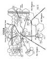
- The CMRS system of Fig. 1 illustrates an arrangement having 7 cells each having voice and data connections to a network control system ((NCS). The NCS is in turn connected to the telephone network.
- Each cell uses one or more of 21 channels as set-up channels to broadcast continuously certain routine or overhead information which permits the mobiles to select the nearest cell, identify the system, etc.
- The CMRS system continuously transmits digital data on each cell set-up channel including such information as the CMRS system identification, overload control ("line load" control), synchronizing bits, busy-idle status of reverse signaling channel and signaling channel numbers used in this location.
- If a call was made to a Home Mobile Unit (HMU) directory number, the system would try to page it by sending out the car directory number on paging (set-up) channels. Receiving no response, the NCS can return such an indication to the calling subscriber in the form of an announcement. (If the called mobile unit is turned on and answers the page, the mobile will be "rung" and the callerwill receive ringbacktone indicating that the mobile is in the area and turned on). When the mobile unit first turns on his radiotelephone, it first scans all set-up channels. The unit would verify that is was in its home area and the paging (or set-up) channels and voice channels used in this complex would be identified to the mobile unit. The mobile unit would then scan the identified set-up channel and select and tune to the strongest one, presumably the nearest cell transmitter. "Busy-idle" bits inform the mobile unit the status of the reverse (mobile to base) signaling channel to prevent simultaneous seizure by more than one mobile unit. (There are also other handshake and timing checks to guard against "collisions".)
- The mobile unit now automatically "reports in" to the system and sends its unit serial number, its assigned telephone number (7 or 10 digits), its power level, etc. and turns off it transmitter, continuing to monitor the selected set-up channel for a page.
- The NCS "registers" the mobile unit as either a home or foreign unit. Depending upon system procedures, the registration could verify that service has not been discontinued or is not on a "hot list" relating to unauthorized use or stolen units.
- On a call to mobile, the NCS directs the paging (7 digit number) to be sent on the appropriate paging channels. The mobile receives the page and detects that it coincides with its assigned telephone number. it acknowledges on a selected set-up channel by sending back its identification number. The NCS selects a voice channel and advises the mobile to switch to that channel, abandoning the set-up channel. The mobile acknowledges that he is now tuned to the selected voice channel by an in-band SAT (supervisory) tone. The NCS directs the base RF equipment to send an alerting data burst over the voice channel and the mobile begins the audible alert (ringing). The mobile returns an out of band signaling tone acknowledging that it is in a ringing process and the NCS returns ringback to the calling party. When the mobile is answered, the signaling tone is removed and the call cut through.
- On a call from a mobile, a similar procedure occurs. Assuming that the mobile has "signed in" with his radio on, he will already be registered in the NCS as a bona fide unit. To initiate a call, the mobile subscriber will enter the dialed digits of the called number and they are temporarily stored in the mobile unit.
- Then the mobile goes "off hook" and scans and selects the strongest set-up channel. When the "busy-idle" bit signifies the channel is idle, the mobile sends identification and the dialed digits to the NCS. The mobile unit then waits for a voice channel assignment and, by supervisory and signaling tones associated with the assigned channel, provides the neessary answer supervision, disconnect, etc. The set-up channels are used only very briefly during the identification, location and voice channel assignment process. Since this is a big "party line" or common channel, occupancy must be limited. Once a two- way voice channel is established between the mobile and the cell site, all supervisory signals occur via in-band (SAT) or out of band (ST) tones.
- Regardless of whether a call was originated by or completed to a mobile unit, a feature of CMRS is that so long as the mobile stays within the CMRS service area, voice communications will be maintained. As the mobile unit moves, the signal strength as received by various cell sites is transmitted to the NCS. The NCS decides when a "hand-off" to another cell is advisable based upon relative signal strength, next cell congestion, etc. The NCS enables the new cell and selects a new channel. A signal to switch to a new channel is sent to the mobile over the current serving channel by means of a very short digital burst which is not detectable by the listener. The mobile sends a disconnect signal tone, turns off its transmitter, re-tunes to the new channel and sends supervisory tone. The NCS recognizes the successful hand-off and switches circuits to the new cell site. The calling and called party are not aware of the hand-off since it occurs within milliseconds.
- If the mobile is a "roamer" from another CMRS system (though perhaps serving the same area), it will be designated a Foreign Mobile Unit (FMU) in this area. Operation is almost identical except that local calls from the FMU are probably billable and must be recorded with calling details.
- "Roamers" might be given a different priority of service, require validity checks from a distant data bank, etc. Also, since they do not have a local number, terminating calls present different problems. Since the FMU automatically registered his 10 digit number in the NCS, the paging and answer process is similar to that for a HMU.
- The block diagram of Fig. 2 illustrates the NCS and one cell site of the system of Fig. 1 in greater detail. The NCS equipment includes the commercially available ITT System 1210 hardware and software. The basic configuration shown in Fig. 2 includes the ITT System 1210 processor as network control; direct memory access (DMA) equipment; switch groups; a line switch to accomodate service circuits such as DTMFR, MFR conference circuits, line interface (cc) and operator interface (OPI); various I/0 peripherals such as TTY, magnetic tape (MT) and terminals (CRT); trunks; and a system test frame, tone and recorded announcement source, which are not shown in Fig. 1.
- Additionally software for providing specific functions for cellular radio is provided. The NCS further includes a pool of control concentrators coupled between the switch group matrix and the DMA via channel units, modems if necessary, and signal conditioning circuits.
- The NCS is coupled to the cell site via transmission facilities which in the example shown are TI spans. The cell site includes a plurality of specialized use transceivers including set-up radio transceiver, data channel transceivers, voice channel transceivers, locating radio receivers, paging transmitters, and base radio test equipment. It should be noted that each of the trnans- ceivers, receivers or transmitters may be of type as described in the aforementioned Bell System Technical Journal reference or may be of any other types including types having microprocessor control. Each transceiver, receiver, transmitter has bidirectional control ports for the exchange of control information with the NCS. Additionally, the voice channel transceivers and the base radio test equipment have a bidirectional audio signal port; the data channel transceiver has bidirectional data ports. The audio signal ports are coupled via a 4-wire voice frequency facility to channel units contained in a channel bank which is in turn coupled to the TI span and thus to the switch matrix in the NCS. Each bidirectional control port is duplicated and is coupled to the statistical multiplexers A and B. The statistical multiplexers are in turn coupled to channel units in the channel banks which in turn are coupled to -the TI span and thus to switch matrix in the NCS. It should be noted that redundancy is provided for reliability purposes.
- The statistical multiplexers shown in Fig. 2 and also in the other figures to be described below may be of the commerically available types described by Harry J. Hindin in "controlling data communications: statistical multiplexer move in",Electronics, July 28,1981, p. 141-148 and by J.H. Scharen-Guivel and A.A. Carlson in "A buyers guide to todays versatile statistical multiplexers", Data Communications, March, 1982, pp. 97-126.
- Generally, a statistical multiplexer is utilized to multiplex a number of terminals to a data link. Conventional time division multiplexers of either the bit-or the character-interleaving type assign dedicated time slots to each terminal. With statistical multiplexing the available bandwidth of the trunk is allocated dynamically. When the output link capacity is exceeded, incoming data from the terminals is buffered and queued by the multiplexer's microprocessors and random access memory until it can be accommodated. The statistical multiplexer also performs demultiplexing operations for coupling information from the data link to the terminals by using the inverse of the process described above.
- It appears from the literature that statistical multiplexers are used in pairs one on one each end of the data link acting in complementary fashion. However, as is evident from Fig. 2, the embodiment of the invention utilizes statistical multiplexers on only one end of a link. The reasons for so doing will become apparent from the description below of Figs. 3 through 6.
- The control arrangement of Fig. 6 illustrates the NCS (Fig. 5) coupled via analog transmission facility (Fig. 3) to one cell and coupled via digital transmission facility (Fig. 4) to another cell. For simplicity, each of the cells is shown as having three
voice channel transceivers transceiver 34. Each voice channel transceiver has a pair of duplicated control ports control A, control B, respectively coupled to a pair ofstatistical multiplexers statistical multiplexer RS 232/422, 423 signaling classes. - Where analog transmission facilities as in Fig. 3 connects the cell site to the NCS, a standard commercially
available modem 37 is used to convert the signals between theRS 232/422, 423 signaling classes to inband audio tones on ananalog transmission facility 38 which is terminated at the NCS via a channel unit contained in channel bank 51. - Where digital transmission facilities as in Fig. 4 connect the cell site to the NCS, the data link side of the
statistical multiplexer - It should be noted that one skilled in the art will recognize that various combinations of analog and digital transmission facilities may be used between the NCS and each cell site.
- All control signal exchanges between the NCS and the
statistical multiplexers statistical mulitplexers - For normal, non-maintenance, cell-site operation, it is sufficient for only one statistical multiplexer of each redundant pair to provide control signal exchanges with the NCS. Therefore, in normal, non-maintenance operation the NCS will establish a path through the digital matrix connnecting only one statistical multiplexer of each redundant pair to a terminal at the right side of the
digital matrix 52. A plurality ofchannel banks 54 are coupled to the terminals at the right side of thedigital matrix 52. The channel banks include data channel units corresponding to the data channel units utilized in the channel banks of Fig. 4 and voice units connected tomodems 55 as in Fig. 3. The data channel units andmodems 55 are coupled to ports on a plurality ofcontrol concentrators 56 which are in turn coupled to the direct memory access DMA of the central processing unit CPU. - The communications from a plurality of transceivers is placed on the facility toward the control concentrators in a byte interleaved basis by the statistical multiplexers. Communications from a plurality of statistical multiplexers are byte deleaved and packetized by the control concentrator and serially presented to the DMA via
signal conditioning circuits 59. Thus, thecontrol concentrators 56 each serve to reformat and multiplex the communications from a plurality of statistical multiplexers thereby providing another level of multiplexing and concentration of control. Eachcontrol concentrator 56 shown in greater detail in Fig. 7 includes a microprocessor 71 having I/O ports, some of which are coupled to the statistical multiplexers via the matrix and one or a few of which are connected to the DMA. A random access memory 72 is coupled to the microprocessor 71 as are various peripherals such as a disk unit and a tape unit. The memory 72 is a 512K bytes of 32 byte memory. - Turning back to Fig. 6, although two control concentrators are shown, it should be understood that in illustrative embodiment it is contemplated that the number M of control concentrator required is N/X where N=the number of redundant pairs of statistical multiplexers, and X= the number of statistical multiplexer ports available at one control concentrator. Where the fraction N/X is not a whole number, M will be the next highest whole number. Additionally for reliability, spare control concentrators may be added to the pool of control concentrators.
- Taking into account reliability considerations, the number of control concentrators required for a system having N pairs of statistical multiplexers is M+X where X is the number of spare units required to achieve the desired availability.
- Fig. 8 illustrates another advantageous configuration of a CMRS system wherein portions of the switching matrix are remoted from the NCS. This Remote Switch Group (RSG) arrangement operates under its own microprocessor control with sufficient intelligence to switch port-to-port traffic and perform routine tasks under host NCS direction.
- When RSG's are used, calls originating and terminating within a community of interest served by a RSG do no require back-haul voice circuit to the NCS. Control links (duplicated for reliability) from the NCS establish the RSG port-to-port connections, and the voice circuit is switched from the RSG directly into a local office or onto an outgoing trunk.
- The RSG is a remote (from NCS) switching node within the cellular network, and consists in its most basic configuration of two or more standard ITT 1210 switch groups, a digital tone supply, a Stratum III synchronizable clock, and digital or analog trunks as required (see Fig. 10). Service circuits (MFR, conference circuits, etc.) and recorded announcement sources reside in the host NCS and are assigned dedicated channels in the NSC-to-RSG link route. Service circuits and announcement machines may be added in the RSG when its size and common traffic interest with the NCS make this desirable. The synchronizable clock is required to keep the digital RSG matrix synchronized with the NCS and digital links.
- Two of the RSG switch groups are equipped with special interfaces to the digital tone supply (TAG) and synch clock for maintenance and alarm control access by the NCS system controller.
- The NCS controller data structure is arranged to provide separate translation domains for each RSG. Thus allows individual routing patters for a given called number that are unique to that translation domain. Multiple translation domains per RSG (or NCS) can also be assigned.
- All central processing of calls, maintenance, and administrative routines is performed by the NCS system controller as in the standard system configuration. The functions performed by the RSG switch group controllers and the RSG subtending CSC's are identical to those performed by the NCS switch groups and the NCS subtending CSC's. A minor exception is the previously mentioned remote maintenance and alarm control port operation.
- As shown in Fig. 9, the links consist of standard TI span ones (or TI compatible facilities). Digital channel banks with individual channel Drop/Insert ports at each end are used for control communication between the NCS system controller and the RSG switch group controllers. Two channels per remote switch group controller (on separate TI lines for reliability) are used, and the number of channels dropped/inserted thus depends on the number of individual switch groups in the RSG.
- The switched through control concept which was applied to the arrangements of Figs. 1-7 can further advantageously be used for the arrangement of Fig. 8 as shown in Fig. 10. The control between the NCS and individual RSG's is accomplished by establishing a path from the DMA of the NCS through the NCS's matrix over transmission facility to the RSG through its matrix to the switch group (SWG) control of the RSG. Two channels per RSG controller are used for reliability.
- A large cellular geographic area may be served by multiple NCS's each of which is remote from the others as shown in Fig. 11. The switched through control concept may still further advantageously be applied to such an arrangement as shown in Fig. 12 wherein a control path may be established between the two NCS's X, Y by establishing a path through the matrix of NCS X, over transmission facility to the other NCS, Y through its matrix and control concentrator.
Claims (2)
Applications Claiming Priority (2)
| Application Number | Priority Date | Filing Date | Title |
|---|---|---|---|
| US457155 | 1983-01-11 | ||
| US06/457,155US4562572A (en) | 1983-01-11 | 1983-01-11 | Cellular mobile radio service telephone system |
Publications (3)
| Publication Number | Publication Date |
|---|---|
| EP0113662A2 EP0113662A2 (en) | 1984-07-18 |
| EP0113662A3 EP0113662A3 (en) | 1986-08-20 |
| EP0113662B1true EP0113662B1 (en) | 1990-08-16 |
Family
ID=23815662
Family Applications (1)
| Application Number | Title | Priority Date | Filing Date |
|---|---|---|---|
| EP84100056AExpiredEP0113662B1 (en) | 1983-01-11 | 1984-01-04 | Cellular mobile radio service telephone system |
Country Status (8)
| Country | Link |
|---|---|
| US (1) | US4562572A (en) |
| EP (1) | EP0113662B1 (en) |
| JP (1) | JPS59171337A (en) |
| AU (1) | AU567906B2 (en) |
| CA (1) | CA1234601A (en) |
| DE (1) | DE3482963D1 (en) |
| ES (1) | ES8503181A1 (en) |
| HK (1) | HK50191A (en) |
Cited By (2)
| Publication number | Priority date | Publication date | Assignee | Title |
|---|---|---|---|---|
| US5657358A (en) | 1985-03-20 | 1997-08-12 | Interdigital Technology Corporation | Subscriber RF telephone system for providing multiple speech and/or data signals simultaneously over either a single or plurality of RF channels |
| US5852604A (en) | 1993-09-30 | 1998-12-22 | Interdigital Technology Corporation | Modularly clustered radiotelephone system |
Families Citing this family (59)
| Publication number | Priority date | Publication date | Assignee | Title |
|---|---|---|---|---|
| US4726014A (en)* | 1983-01-11 | 1988-02-16 | U.S. Holding Company, Inc. | Cellular mobile radio service telephone system |
| JPS60143037A (en)* | 1983-12-29 | 1985-07-29 | Nippon Telegr & Teleph Corp <Ntt> | mobile radio communication system |
| AU577742B2 (en)* | 1984-07-13 | 1988-09-29 | Motorola, Inc. | Cellular voice and data radiotelephone system |
| USRE37141E1 (en) | 1984-09-10 | 2001-04-17 | Spectrum Information Technologies, Inc. | Cellular telephone data communication system and method |
| USRE34034E (en)* | 1985-10-11 | 1992-08-18 | Spectrum Information Technologies, Inc. | Cellular telephone data communication system and method |
| US4697281A (en)* | 1986-03-14 | 1987-09-29 | Spectrum Cellular Communications Corporation, Inc. | Cellular telephone data communication system and method |
| DE3502942A1 (en)* | 1985-01-30 | 1986-07-31 | ANT Nachrichtentechnik GmbH, 7150 Backnang | DIGITAL MOBILE RADIO SYSTEM |
| US4829554A (en)* | 1985-01-31 | 1989-05-09 | Harris Corporation | Cellular mobile telephone system and method |
| US4910765A (en)* | 1986-04-30 | 1990-03-20 | Ricoh Company, Ltd. | Communication terminal apparatus having a relaying function |
| US4677653A (en)* | 1986-06-16 | 1987-06-30 | B/W Investments | Cellular mobile phone with a plurality of accessing telephone numbers for allowing access to the mobile phone by any one of the telephone numbers |
| US5210786A (en)* | 1986-10-15 | 1993-05-11 | Iwatsu Electric Co. Ltd. | Portable telephone system using stratified exchange system |
| US4777633A (en)* | 1987-08-14 | 1988-10-11 | International Mobile Machines Corp. | Base station for wireless digital telephone system |
| US4775999A (en)* | 1986-10-31 | 1988-10-04 | Motorola, Inc. | Registration of radiotelephones in networked cellular radiotelephone systems |
| CA1250900A (en)* | 1986-11-18 | 1989-03-07 | Northern Telecom Limited | Private cellular system |
| EP0309572B1 (en)* | 1987-04-10 | 1994-06-15 | Motorola, Inc. | Registration of radiotelephones in networked cellular radiotelephone systems |
| WO1988009969A1 (en)* | 1987-06-03 | 1988-12-15 | General Electric Company | Process-to-processor communications protocol for a public service trunking system |
| US4835731A (en)* | 1987-08-14 | 1989-05-30 | General Electric Company | Processor-to-processor communications protocol for a public service trunking system |
| US5128930A (en)* | 1987-08-14 | 1992-07-07 | General Electric Company | Processor-to-processor communications protocol for a public service trunking system |
| US5206863A (en)* | 1987-08-14 | 1993-04-27 | General Electric Company | Processor-to-processor communications protocol for a public service trunking system |
| US5280521A (en)* | 1987-10-09 | 1994-01-18 | Iwatsu Electric Co., Ltd. | Portable telephone system |
| US4833701A (en)* | 1988-01-27 | 1989-05-23 | Motorola, Inc. | Trunked communication system with nationwide roaming capability |
| GB8814176D0 (en)* | 1988-06-15 | 1988-07-20 | Marconi Gec Ltd | Communication systems |
| USRE38645E1 (en) | 1989-01-19 | 2004-11-02 | Mlr, Llc | Portable hybrid communication system and methods |
| GB2238207A (en)* | 1989-10-26 | 1991-05-22 | Motorola Ltd | Information network |
| US5127041A (en)* | 1990-06-01 | 1992-06-30 | Spectrum Information Technologies, Inc. | System and method for interfacing computers to diverse telephone networks |
| US5018187A (en)* | 1990-06-05 | 1991-05-21 | At&T Bell Laboratories | Mobile telephone intrasystem and intersystem enhanced handoff method and apparatus for limiting trunk switching connections |
| GB9013605D0 (en)* | 1990-06-18 | 1990-08-08 | Stc Plc | Mobile communications |
| SE9100117L (en)* | 1991-01-14 | 1992-07-15 | Ellemtel Utvecklings Ab | NETWORK STRUCTURE FOR THE MOBILE PHONE |
| DE4118849A1 (en)* | 1991-06-07 | 1992-12-10 | Philips Patentverwaltung | MOBILE RADIO |
| NZ243007A (en)* | 1991-06-19 | 1995-02-24 | Ericsson Telefon Ab L M | Radio telephony: digital speech codec provided at regional stations for analog transmissions |
| CA2066538C (en)* | 1991-07-09 | 1997-12-23 | Brian David Bolliger | Mobile-telephone system call processing arrangement |
| US5195090A (en)* | 1991-07-09 | 1993-03-16 | At&T Bell Laboratories | Wireless access telephone-to-telephone network interface architecture |
| CA2067637C (en)* | 1991-07-29 | 1997-11-18 | John Lappington | System for distributing radio telephone signals over a cable television network |
| US6400702B1 (en)* | 1991-10-01 | 2002-06-04 | Intermec Ip Corp. | Radio frequency local area network |
| US5309503A (en)* | 1991-12-06 | 1994-05-03 | Motorola, Inc. | Dynamic channel assignment in a communication system |
| US5579379A (en)* | 1992-03-05 | 1996-11-26 | Bell Atlantic Network Services, Inc. | Personal communications service having a calling party pays capability |
| US5353331A (en)* | 1992-03-05 | 1994-10-04 | Bell Atlantic Network Services, Inc. | Personal communications service using wireline/wireless integration |
| US5341410A (en)* | 1992-07-21 | 1994-08-23 | Ram Mobile Data Usa Limited Partnership | Cellular telephone locator using a mobile data system |
| CA2107757C (en)* | 1992-12-18 | 1998-07-07 | Bruce Merrill Bales | Telecommunication switching system having transparent wireless features |
| US5499386A (en)* | 1993-07-09 | 1996-03-12 | Telefonaktiebolaget L M Ericsson | Best server selection in layered cellular radio system |
| US5422935A (en)* | 1993-07-13 | 1995-06-06 | Motorola, Inc. | Method of and apparatus for providing a local PSTN interconnect with a cellular base site |
| US5758287A (en)* | 1994-05-20 | 1998-05-26 | Airtouch Communications, Inc. | Hub and remote cellular telephone system |
| US5537460A (en)* | 1994-07-08 | 1996-07-16 | Holliday, Jr.; Robert O. | Method and apparatus for determining the precise location of a modified cellular telephone using registration messages and reverse control channel transmission |
| US5673308A (en)* | 1994-10-12 | 1997-09-30 | Bell Atlantic Network Services, Inc. | Personal phone number system |
| US5715174A (en)* | 1994-11-15 | 1998-02-03 | Absolute Software Corporation | Security apparatus and method |
| MY121893A (en)* | 1995-04-28 | 2006-03-31 | Qualcomm Inc | Method and apparatus for providing variable rate data in a communications system using statistical multiplexing. |
| US5621787A (en)* | 1995-09-13 | 1997-04-15 | Bell Atlantic Network Services, Inc. | Prepaid cash card |
| US5822776A (en)* | 1996-03-11 | 1998-10-13 | Mitel Corporation | Multiplexed random access memory with time division multiplexing through a single read/write port |
| US5859840A (en)* | 1996-05-31 | 1999-01-12 | Qualcomm Incorporated | Spread spectrum communication system which defines channel groups comprising selected channels that are additional to a primary channel and transmits group messages during call set up |
| US6496543B1 (en)* | 1996-10-29 | 2002-12-17 | Qualcomm Incorporated | Method and apparatus for providing high speed data communications in a cellular environment |
| US6173007B1 (en) | 1997-01-15 | 2001-01-09 | Qualcomm Inc. | High-data-rate supplemental channel for CDMA telecommunications system |
| US6335922B1 (en) | 1997-02-11 | 2002-01-01 | Qualcomm Incorporated | Method and apparatus for forward link rate scheduling |
| US7751370B2 (en) | 2001-07-13 | 2010-07-06 | Qualcomm Incorporated | Method and apparatus for forward link rate scheduling |
| US6480521B1 (en) | 1997-03-26 | 2002-11-12 | Qualcomm Incorporated | Method and apparatus for transmitting high speed data in a spread spectrum communications system |
| US6389000B1 (en) | 1997-09-16 | 2002-05-14 | Qualcomm Incorporated | Method and apparatus for transmitting and receiving high speed data in a CDMA communication system using multiple carriers |
| US6289201B1 (en)* | 1998-10-02 | 2001-09-11 | Motorola, Inc. | Method and system for multilayer service management |
| US6611511B1 (en) | 1999-03-04 | 2003-08-26 | Cellco Partnership | Cellular telephone communication system using sector splitting for improved performance |
| US8601606B2 (en) | 2002-11-25 | 2013-12-03 | Carolyn W. Hafeman | Computer recovery or return |
| US9547780B2 (en)* | 2005-03-28 | 2017-01-17 | Absolute Software Corporation | Method for determining identification of an electronic device |
Family Cites Families (8)
| Publication number | Priority date | Publication date | Assignee | Title |
|---|---|---|---|---|
| CA977476A (en)* | 1971-04-15 | 1975-11-04 | Giancarlo Monti | Digital voice interpolation system for pcm systems |
| US4028500A (en)* | 1973-05-15 | 1977-06-07 | Martin Marietta Corporation | Mobile unit supervisory control sequencer and method |
| US3984807A (en)* | 1973-11-05 | 1976-10-05 | Products Of Information Systems | Vehicle location system |
| JPS52130589A (en)* | 1976-04-26 | 1977-11-01 | Nippon Telegr & Teleph Corp <Ntt> | Mobile radio controllig system |
| JPS5819176B2 (en)* | 1977-05-21 | 1983-04-16 | 三菱電機株式会社 | Mobile station position determination device |
| IL56382A (en)* | 1978-02-13 | 1981-05-20 | Motorola Inc | Method and apparatus for a radiotelephone communications system |
| JPS5547745A (en)* | 1978-08-25 | 1980-04-04 | Nec Corp | Mobile communication system |
| JPS55166326A (en)* | 1979-06-12 | 1980-12-25 | Nec Corp | Channel switching circuit |
- 1983
- 1983-01-11USUS06/457,155patent/US4562572A/ennot_activeExpired - Lifetime
- 1984
- 1984-01-04DEDE8484100056Tpatent/DE3482963D1/ennot_activeExpired - Lifetime
- 1984-01-04EPEP84100056Apatent/EP0113662B1/ennot_activeExpired
- 1984-01-10AUAU23177/84Apatent/AU567906B2/ennot_activeCeased
- 1984-01-10CACA000445007Apatent/CA1234601A/ennot_activeExpired
- 1984-01-11JPJP59002117Apatent/JPS59171337A/enactivePending
- 1984-01-11ESES528793Apatent/ES8503181A1/ennot_activeExpired
- 1991
- 1991-07-04HKHK501/91Apatent/HK50191A/enunknown
Cited By (13)
| Publication number | Priority date | Publication date | Assignee | Title |
|---|---|---|---|---|
| US6771667B2 (en) | 1985-03-20 | 2004-08-03 | Interdigital Technology Corporation | Subscriber RF telephone system for providing multiple speech and/or data signals simultaneously over either a single or a plurality of RF channels |
| US5687194A (en) | 1985-03-20 | 1997-11-11 | Interdigital Technology Corporation | Subscriber RF telephone system for providing multiple speech and/or data signals simultaneously over either a single or a plurality of RF channels |
| US5734678A (en) | 1985-03-20 | 1998-03-31 | Interdigital Technology Corporation | Subscriber RF telephone system for providing multiple speech and/or data signals simultaneously over either a single or a plurality of RF channels |
| US6014374A (en) | 1985-03-20 | 2000-01-11 | Interdigital Technology Corporation | Subscriber RF telephone system for providing multiple speech and/or data signals simultaneously over either a single or a plurality of RF channels |
| US6282180B1 (en) | 1985-03-20 | 2001-08-28 | Interdigital Technology Corporation | Subscriber RF telephone system for providing multiple speech and/or data signals simultaneously over either a single or a plurality of RF channels |
| US6393002B1 (en) | 1985-03-20 | 2002-05-21 | Interdigital Technology Corporation | Subscriber RF telephone system for providing multiple speech and/or data signals simultaneously over either a single or a plurality of RF channels |
| US5657358A (en) | 1985-03-20 | 1997-08-12 | Interdigital Technology Corporation | Subscriber RF telephone system for providing multiple speech and/or data signals simultaneously over either a single or plurality of RF channels |
| US6842440B2 (en) | 1985-03-20 | 2005-01-11 | Interdigital Technology Corporation | Subscriber RF telephone system for providing multiple speech and/or data signals simultaneously over either a single or a plurality of RF channels |
| US6954470B2 (en) | 1985-03-20 | 2005-10-11 | Interdigital Technology Corporation | Subscriber RF telephone system for providing multiple speech and/or data signals simultaneously over either a single or a plurality of RF channels |
| US5852604A (en) | 1993-09-30 | 1998-12-22 | Interdigital Technology Corporation | Modularly clustered radiotelephone system |
| US6208630B1 (en) | 1993-09-30 | 2001-03-27 | Interdigital Technology Corporation | Modulary clustered radiotelephone system |
| US6496488B1 (en) | 1993-09-30 | 2002-12-17 | Interdigital Technology Corporation | Modularly clustered radiotelephone system |
| US7245596B2 (en) | 1993-09-30 | 2007-07-17 | Interdigital Technology Corporation | Modularly clustered radiotelephone system |
Also Published As
| Publication number | Publication date |
|---|---|
| ES528793A0 (en) | 1985-01-01 |
| AU2317784A (en) | 1984-07-12 |
| DE3482963D1 (en) | 1990-09-20 |
| US4562572A (en) | 1985-12-31 |
| CA1234601A (en) | 1988-03-29 |
| ES8503181A1 (en) | 1985-01-01 |
| HK50191A (en) | 1991-07-12 |
| JPS59171337A (en) | 1984-09-27 |
| EP0113662A2 (en) | 1984-07-18 |
| AU567906B2 (en) | 1987-12-10 |
| EP0113662A3 (en) | 1986-08-20 |
Similar Documents
| Publication | Publication Date | Title |
|---|---|---|
| EP0113662B1 (en) | Cellular mobile radio service telephone system | |
| US4726014A (en) | Cellular mobile radio service telephone system | |
| US5440613A (en) | Architecture for a cellular wireless telecommunication system | |
| US5655001A (en) | Wireless telecommunication system using protocol conversion for signaling between base stations and land based switches | |
| CA1166316A (en) | Cellular high capacity mobile radiotelephone system with fleet-calling arrangement for dispatch service | |
| US4284848A (en) | Switched network telephone subscriber distribution system | |
| US4748655A (en) | Portable telephones | |
| CA1274009A (en) | Tdma communication system having common local path medium and local time slot for intraoffice calls | |
| KR100394284B1 (en) | Method and apparatus for providing inter-switch handovers | |
| JPH09503634A (en) | Distributed telecommunications switching system | |
| US5274694A (en) | Radio communication network based on digital local exchanges | |
| CA2097351C (en) | Architecture for a wireless telecommunication system | |
| US5353333A (en) | Small wireless telecommunications system | |
| US6055411A (en) | Radio communication system having a wireless cell site | |
| GB2173377A (en) | Alternate cell routing for cellular mobile radio | |
| US5999810A (en) | Architecture for a wireless telecommunication system | |
| US5812541A (en) | Simplified wireless subscriber system adapted for CDMA radio transmission | |
| FI98482C (en) | Switching station for radio mobile phone use | |
| US5956631A (en) | Multiple terminal device ringing digital subscriber ISDN terminal | |
| CA1289282C (en) | Subscriber-concentrated communication system | |
| PL182153B1 (en) | Subscriber connection network for connecting subscribbers to a data transmission exchange using a radio transmission system | |
| JPH0716265B2 (en) | Circuit allocation system Switching system by subscriber line | |
| Stte | S kkkkkS | |
| JPS6327150A (en) | Satellite channel relaying system for mobile communication | |
| WO1995022870A2 (en) | Establishment of a prioritized telecommunication connection |
Legal Events
| Date | Code | Title | Description |
|---|---|---|---|
| PUAI | Public reference made under article 153(3) epc to a published international application that has entered the european phase | Free format text:ORIGINAL CODE: 0009012 | |
| AK | Designated contracting states | Designated state(s):AT BE CH DE FR GB IT LI LU NL SE | |
| RBV | Designated contracting states (corrected) | Designated state(s):DE FR GB IT SE | |
| PUAL | Search report despatched | Free format text:ORIGINAL CODE: 0009013 | |
| AK | Designated contracting states | Kind code of ref document:A3 Designated state(s):DE FR GB IT SE | |
| 17P | Request for examination filed | Effective date:19861121 | |
| RAP1 | Party data changed (applicant data changed or rights of an application transferred) | Owner name:ALCATEL N.V. | |
| RAP3 | Party data changed (applicant data changed or rights of an application transferred) | Owner name:ALCATEL N.V. | |
| 17Q | First examination report despatched | Effective date:19880822 | |
| GRAA | (expected) grant | Free format text:ORIGINAL CODE: 0009210 | |
| AK | Designated contracting states | Kind code of ref document:B1 Designated state(s):DE FR GB IT SE | |
| REF | Corresponds to: | Ref document number:3482963 Country of ref document:DE Date of ref document:19900920 | |
| ITF | It: translation for a ep patent filed | ||
| ET | Fr: translation filed | ||
| ITTA | It: last paid annual fee | ||
| PLBE | No opposition filed within time limit | Free format text:ORIGINAL CODE: 0009261 | |
| STAA | Information on the status of an ep patent application or granted ep patent | Free format text:STATUS: NO OPPOSITION FILED WITHIN TIME LIMIT | |
| 26N | No opposition filed | ||
| PGFP | Annual fee paid to national office [announced via postgrant information from national office to epo] | Ref country code:GB Payment date:19911211 Year of fee payment:9 | |
| PGFP | Annual fee paid to national office [announced via postgrant information from national office to epo] | Ref country code:FR Payment date:19911230 Year of fee payment:9 | |
| PGFP | Annual fee paid to national office [announced via postgrant information from national office to epo] | Ref country code:SE Payment date:19920103 Year of fee payment:9 | |
| PG25 | Lapsed in a contracting state [announced via postgrant information from national office to epo] | Ref country code:GB Effective date:19930104 | |
| PG25 | Lapsed in a contracting state [announced via postgrant information from national office to epo] | Ref country code:SE Effective date:19930105 | |
| PGFP | Annual fee paid to national office [announced via postgrant information from national office to epo] | Ref country code:DE Payment date:19930227 Year of fee payment:10 | |
| GBPC | Gb: european patent ceased through non-payment of renewal fee | Effective date:19930104 | |
| PG25 | Lapsed in a contracting state [announced via postgrant information from national office to epo] | Ref country code:FR Effective date:19930930 | |
| REG | Reference to a national code | Ref country code:FR Ref legal event code:ST | |
| PG25 | Lapsed in a contracting state [announced via postgrant information from national office to epo] | Ref country code:DE Effective date:19941001 | |
| EUG | Se: european patent has lapsed | Ref document number:84100056.5 Effective date:19930810 |