EP0112414B1 - Image transformations on an interactive raster scan or matrix display - Google Patents
Image transformations on an interactive raster scan or matrix displayDownload PDFInfo
- Publication number
- EP0112414B1 EP0112414B1EP82306863AEP82306863AEP0112414B1EP 0112414 B1EP0112414 B1EP 0112414B1EP 82306863 AEP82306863 AEP 82306863AEP 82306863 AEP82306863 AEP 82306863AEP 0112414 B1EP0112414 B1EP 0112414B1
- Authority
- EP
- European Patent Office
- Prior art keywords
- cursor
- image
- alternative
- full
- screen
- Prior art date
- Legal status (The legal status is an assumption and is not a legal conclusion. Google has not performed a legal analysis and makes no representation as to the accuracy of the status listed.)
- Expired
Links
Images


Classifications
- G—PHYSICS
- G06—COMPUTING OR CALCULATING; COUNTING
- G06F—ELECTRIC DIGITAL DATA PROCESSING
- G06F3/00—Input arrangements for transferring data to be processed into a form capable of being handled by the computer; Output arrangements for transferring data from processing unit to output unit, e.g. interface arrangements
- G06F3/01—Input arrangements or combined input and output arrangements for interaction between user and computer
- G06F3/048—Interaction techniques based on graphical user interfaces [GUI]
- G06F3/0481—Interaction techniques based on graphical user interfaces [GUI] based on specific properties of the displayed interaction object or a metaphor-based environment, e.g. interaction with desktop elements like windows or icons, or assisted by a cursor's changing behaviour or appearance
- G06F3/04812—Interaction techniques based on cursor appearance or behaviour, e.g. being affected by the presence of displayed objects
- G—PHYSICS
- G06—COMPUTING OR CALCULATING; COUNTING
- G06T—IMAGE DATA PROCESSING OR GENERATION, IN GENERAL
- G06T11/00—2D [Two Dimensional] image generation
Definitions
- the inventionrelates to an interactive raster scanned or matrix display system of the type which permits two-way communication between a user of the system and a computer included as part of the system.
- the computerprovides the control for the display so that, for example, upon receipt of signals from an input device operated by the user, a displayed picture is modified appropriately. It is desirable for the modification to occur rapidly so that to the user it appears that the picture is changing instantaneously in response to the commands.
- the inventionrelates in particular to the use of such a display system for performing image transformation on the screen where such transformation is made under the direct control of a user interacting with the system by means of a cursor positioning device.
- graphical input devicessuch as joysticks, tracker balls, tablets etc. available by means of which a user can identify a particular location or image on the screen. It is also possible to identify a position on the screen by using a keyboard propelled cursor. Here, a set of four keys may be assigned to step the cursor in each of the two directions vertically and horizontally.
- the effectiveness of these input devicesdepends on the use of visual feedback to the user provided by a cursor displayed at the screen coordinates defined by the coordinate outputs of the device. By controlling movement of the device, the user can steer the cursor around the screen.
- the procedure involvedincludes the user moving a cursor to overlay a point on the image in question and then issuing a signal by means of an assigned keybutton for example, to notify the computer that a transformation function is to be performed on the image, pointed to by the cursor.
- the computerthen operates to link the image to the cursor so that, for example, if the transformation involves moving the image across the screen, the user can drag the image to its new position simply by moving the cursor with the input device.
- the images to be movedmay include graphics line drawings, half-tone images, text or combinations of all three.
- a block of text to be movedmay be identified by being enclosed in a box or by pointing to the start and end of the block using a cursor.
- the cursor symbol on the screencan be provided by a special purpose hardware processor.
- a processoris a relatively expensive item in a low cost terminal and also limits the flexibility in terms of shape available to the user. It is therefore becoming increasingly common to generate the cursor by means of software thus enabling cursor shapes and sizes to be selected by the user to suit the application being performed.
- IBM Technical Disclosure Bulletin, Vol. 24, No. 2, pages 1072 - 1074discloses a technique where complex images are replaced by simplified images to speed up system response to a user, the omitted detai,ls being added later as a background task.
- the present inventionis concerned with such problems of image transformation where the drawing engine of the display system is insufficiently powerful to erase and redraw the complex images at the rate demanded by the user controlling the operation.
- the technique employed to overcome this problem according to the present inventionis to arrange during the period of transformation for the automatic substitution of an alternative image of a displayed object which contains less detail to be drawn for the full image and simultaneous for the full screen cross-hair cursor controlling the transformation operation to be replaced by a small cross-hair cursor which also consumes less processing power during movement. As soon as the transformation operation is seen to be complete, the full image of the object and the full screen cross-hair cursor are automatically re-displayed.
- an alternative image for the detailed full imageis preferably such that the user can recognise it as representing the full image for what it is.
- an alternative image for a detailed drawing of a complex objectmay be the simple outline of the object, or perhaps a skeletal line drawing denoting the general shape of the object or, in the case of text processing applications, a block of text to be moved may be represented by an alternative image which is a simple enclosing box for the text.
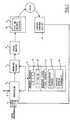
- FIG. 1The basic structure of a general purpose graphics display system on which the present invention is implemented is shown in Figure 1. Such a system is well known in the art and is typical of the type of system described in the referenced chapter of the aforementioned text book by Foley and Van Dam.
- the basic components of a raster display systemare an image creation system, an image storage system, and an image display system, all of which receive commands through an interface of a general purpose computer.
- a microprocessor 1loads display lists of images to be displayed on a visual display unit (VDU) 2, into allocated space in a random access memory 3.
- VDUvisual display unit
- the display listsare in the form of graphic display segments and are provided in known manner by the 'application' being run, over input lines 4 from local peripherals for example, or perhaps over a communications line 5 from a remote unit.
- the display lists of imagesare shown as having been allocated a block 6 of memory 3. It will be understood however that the allocation of space in such a system is under program control and the precise location of individual lists at any instant in time is of no interest.
- the microprocessorpoints to the corresponding display list in block 6, and issues drawing commands to a drawing engine 7 which generates a bit map of the image to be displayed pel by pel on the screen 8.
- the bit mapis loaded into an image refresh buffer 9 which is sampled row by row in synchronism with the line scan of the VDU2 so that the resulting image displayed on the screen 8 is refreshed at the required frame rate.
- the VDUmay be either a cathode ray tube display device or a matrix addressed device such employing for example a gas panel.
- a useris provided with an input cursor control device 10 by means of which a cursor symbol can be moved from point to point over the screen.
- the cursor control devicemay take any of several forms for example a tablet, a trackball, joystick or indeed special purpose cursor key- buttons on a keyboard.
- a meansis provided, usually in the form of a button associated with the device, to enable a user to signal to the application program that the cursor symbol is at a position of interest on the screen.
- the cursor symbolmay be provided by special hardware or, as is becoming increasingly common, in the form of a display list defining the cursor shape stored in allocated space in the image storage system.
- a full cursor display listis shown stored in block 11 in memory 3 and is displayed in the same way as other images by the drawing engine 7 generating a corresponding bit map of the cursor symbol which is loaded into the bit buffer 9 where it is held during display on the screen.
- the cursor position on the screenis defined by coordinate values supplied by the associated cursor control device 10.
- the processor 1enters these coordinate values into a predetermined region of memory 3 set aside for the purpose and for convenience identified as X and Y position registers 12.
- a stream of new coordinate valuesare sent to the microprocessor as a result of a repositioning of the cursor control device by an operator.
- a new coordinate valueis transmitted following for example each incremental movement of the cursor control device or alternatively at predetermined time intervals determined by the system clock.
- the coordinate values arriving in successionform a queue in the microprocessor and are processed one at a time in the order in which they are received.
- the processing stepsinvolve entering the new coordinate value from the head of the queue into the X, Y position registers 12 in memory 3, calculating the transformation using the standard linear transformation matrix for linear displacement, and sending commands to the drawing engine 7 to cause it to erase the cursor symbol at the current screen position and redraw it at the calculated pel positions specified by the new coordinate position defined by the contents of the X, Y position register.
- the drawing engineis capable of erasing and redrawing the cursor symbol at a rate equal to or greater than the rate at which the new incremental position coordinates are received by the microprocessor, then it appears to the user, that the cursor symbol changes instantaneously in response to the cursor commands entered by means of the control device 10.
- the cursorcan be used interactively in conventional manner to identify positions on the screen at which new images are to be displayed, or to 'pick' and transform existing images on the screen.
- the techniques involved for performing these operationsare well known in the art and involve repetitive erasure and redrawing not only the cursor symbol but also the image being transformed.
- the present inventionis aimed at reducing these problems in a low cost terminal where computing power is somewhat limited. From the human factors point of view, it is important that the cursor remains easily identifiable and does not impede the interactive nature of the process by lagging behind its intended position. Also from the human factors point of view it would be a considerable advantage to be able to perform graphics or image transformation at the keying rate for example of a key controlled cursor.
- a cursoris normally drawn large and is therefore easily identifiable even when overlaying a detailed complex line drawn image for example.
- the systemoperates automatically to replace the full screen cross-hair cursor with an alternative cursor image which has less detail to be drawn and therefore can be moved over the screen at a faster rate.
- the full screen cross-hair cursor and its alternative cursorare shown in Figure 2 as screen a and b respectively and may be chosen by the program itself, or they may be selected from images supplied by the user, or the application program.
- the alternative cursoris shown stored as a display list in block 13 of memory 3.
- FIG. 3The flow diagram setting out the sequence of steps performed by the system during a cursor movement across the screen is shown in Figure 3.
- the full cursor specified by the full cursor display list 11is displayed at the current position on the screen.
- the microprocessorinstructs the drawing engine 7 to erase the full cursor.
- the microprocessorissues commands to the drawing engine so that it re-draws at the new calculated position with the incremental transformation applied, not the full cursor, but the alternative cursor defined by alternative cursor display list 13.
- the alternative cursoris erased, the transformation determined by the drawing engine and the alternative cursor redrawn at the transformed position.
- the processcycles around this loop for as long as move requests are supplied.
- the alternative cursoris replaced once again by the full cursor. This requires the time interval from the last alternative cursor move to be monitored. This is achieved by the microprocessor entering the real time (derived from the system clock) at which the last alternative cursor move was made into predetermined storage locations of memory 3 conveniently referred to as time register 15.
- the real time(which of course is continuously incremented at the clock rate of the system) is read and compared with the stored value of the real time in register 15.
- a thresholdis set for the time lag, which is regarded as being sufficiently long since receipt of the last alternative cursor move, so that it can be assumed that the cursor move is complete. In the practical example chosen with the internal clock running at the frame refresh rate of the display (approximately 50 times/second), a lapsed uninterrupted period of 75 counts indicating a time lapse of 1.5 seconds since the last alternative cursor move is considered to be adequate.
- this thresholdis reached, the alternative cursor is erased and replaced by the full cursor which remains displayed until a new cursor move operation is requested.
- a part flow diagram shown in Figure 4details the modification to the cursor move system and is intended to replace the portion of the flow diagram in Figure 3 lying between the point A and B.
- a system operating in catch-up modereads all the input requests for cursor motion and transforms the cursor image in one step to the position it would have been in, had the program been able to keep up.
Landscapes
- Engineering & Computer Science (AREA)
- Theoretical Computer Science (AREA)
- General Engineering & Computer Science (AREA)
- Physics & Mathematics (AREA)
- General Physics & Mathematics (AREA)
- Human Computer Interaction (AREA)
- Processing Or Creating Images (AREA)
- Controls And Circuits For Display Device (AREA)
Description
- The invention relates to an interactive raster scanned or matrix display system of the type which permits two-way communication between a user of the system and a computer included as part of the system.
- In such systems, the computer provides the control for the display so that, for example, upon receipt of signals from an input device operated by the user, a displayed picture is modified appropriately. It is desirable for the modification to occur rapidly so that to the user it appears that the picture is changing instantaneously in response to the commands. The invention relates in particular to the use of such a display system for performing image transformation on the screen where such transformation is made under the direct control of a user interacting with the system by means of a cursor positioning device.
- There are a variety of graphical input devices such as joysticks, tracker balls, tablets etc. available by means of which a user can identify a particular location or image on the screen. It is also possible to identify a position on the screen by using a keyboard propelled cursor. Here, a set of four keys may be assigned to step the cursor in each of the two directions vertically and horizontally. The effectiveness of these input devices depends on the use of visual feedback to the user provided by a cursor displayed at the screen coordinates defined by the coordinate outputs of the device. By controlling movement of the device, the user can steer the cursor around the screen.
- In many interactive applications provision is made for displayed images on the screen to be transformed by the user. The procedure involved includes the user moving a cursor to overlay a point on the image in question and then issuing a signal by means of an assigned keybutton for example, to notify the computer that a transformation function is to be performed on the image, pointed to by the cursor. The computer then operates to link the image to the cursor so that, for example, if the transformation involves moving the image across the screen, the user can drag the image to its new position simply by moving the cursor with the input device. The images to be moved may include graphics line drawings, half-tone images, text or combinations of all three. A block of text to be moved may be identified by being enclosed in a box or by pointing to the start and end of the block using a cursor.
- The cursor symbol on the screen can be provided by a special purpose hardware processor. However such a processor is a relatively expensive item in a low cost terminal and also limits the flexibility in terms of shape available to the user. It is therefore becoming increasingly common to generate the cursor by means of software thus enabling cursor shapes and sizes to be selected by the user to suit the application being performed.
- A general interactive raster-scanned display system which is capable of making image transformations is described in SIGGRAPH- ACM Computer Graphics Vol. 13, No. 3, August 1979. Further information on such systems may be found in
Chapter 12 "Raster Display Architecture" pages 479 to 503 in a text book entitled 'Funda- mentals of Interactive Computer Graphics' by J D Foley and A Van Dam published by Addison-Wolsey Publications Company 1982. Basically in such systems, the individual graphics images that constitute the picture on the screen are stored as individual graphic segments containing the graphic orders. Then transformations may be applied individually to a given graphics segment. This in turn can result in a 'new frame' action, that is the redrawing if necessary of all visible retained information. On a raster-scanned or matrix (e.g. gas panel) display, if there are many images visible and/or the images contain many vectors, it can take a relatively long time, amounting in some cases to several seconds, to redraw the entire picture. - This is particularly a problem on all but high function and consequently high cost systems. The problem in as much as it relates to moving the cursor itself across the screen can be minimised by specifying that it is of small size and simple shape so that it can be erased and redrawn repetitively at a sufficient rate to move it across the screen at the required speed. In the case of a key operated cursor this speed is determined by the automatic typing rate of the keyboard in repetitive mode.
- It has been found however that when interacting with complex graphics line drawings such as integrated circuit layouts or detailed engineering drawings, a small cross-hair cursor for example can be difficult to find. Accordingly, when interacting with such complex images, it has been found to be advantageous to use a large cross-hair cursor extending from screen edge to screen edge both horizontally and vertically.
- The processing power required to erase and redraw these large cursor images is not trivial and the time taken to perform each incremental repositioning can be long compared to the desired speed of interaction. Clearly, the problem is compounded when transforming detailed and complex images under user control where both complex image and cursor are required to be moved over the screen together.
- IBM Technical Disclosure Bulletin, Vol. 24, No. 2, pages 1072-1074 discloses a technique where complex images are replaced by simplified images to speed up system response to a user, the omitted detai,ls being added later as a background task.
- The present invention is concerned with such problems of image transformation where the drawing engine of the display system is insufficiently powerful to erase and redraw the complex images at the rate demanded by the user controlling the operation. The technique employed to overcome this problem according to the present invention is to arrange during the period of transformation for the automatic substitution of an alternative image of a displayed object which contains less detail to be drawn for the full image and simultaneous for the full screen cross-hair cursor controlling the transformation operation to be replaced by a small cross-hair cursor which also consumes less processing power during movement. As soon as the transformation operation is seen to be complete, the full image of the object and the full screen cross-hair cursor are automatically re-displayed.
- The nature of the alternative image for the detailed full image is preferably such that the user can recognise it as representing the full image for what it is. For example, an alternative image for a detailed drawing of a complex object may be the simple outline of the object, or perhaps a skeletal line drawing denoting the general shape of the object or, in the case of text processing applications, a block of text to be moved may be represented by an alternative image which is a simple enclosing box for the text.
- In order that the invention may be fully understood, a preferred embodiment thereof will now be described by way of example with reference to the accompanying drawings.
- In the drawings:
- Figure 1 shows in simplified block form a general purpose raster graphics display system to which the present invention is applied;
- Figure 2 shows a number of typical images as they might appear on a screen during the performance of transformations in accordance with the invention;
- Figure 3 shows a flow diagram setting out the individual steps for invoking an alternative cursor operation performed by a display system in accordance with the invention; and
- Figure 4 shows a modification to the flow diagram in Figure 3 to enable the display system to operate in catch-up mode should the cursor screen position fall behind the user defined position.
- The basic structure of a general purpose graphics display system on which the present invention is implemented is shown in Figure 1. Such a system is well known in the art and is typical of the type of system described in the referenced chapter of the aforementioned text book by Foley and Van Dam. The basic components of a raster display system are an image creation system, an image storage system, and an image display system, all of which receive commands through an interface of a general purpose computer. Thus in the display system shown in Figure 1, a microprocessor 1 loads display lists of images to be displayed on a visual display unit (VDU) 2, into allocated space in a random access memory 3.
- The display lists are in the form of graphic display segments and are provided in known manner by the 'application' being run, over input lines 4 from local peripherals for example, or perhaps over a
communications line 5 from a remote unit. The display lists of images are shown as having been allocated a block 6 of memory 3. It will be understood however that the allocation of space in such a system is under program control and the precise location of individual lists at any instant in time is of no interest. When a particular image is required to be displayed, the microprocessor points to the corresponding display list in block 6, and issues drawing commands to adrawing engine 7 which generates a bit map of the image to be displayed pel by pel on the screen 8. The bit map is loaded into an image refresh buffer 9 which is sampled row by row in synchronism with the line scan of the VDU2 so that the resulting image displayed on the screen 8 is refreshed at the required frame rate. The VDU may be either a cathode ray tube display device or a matrix addressed device such employing for example a gas panel. - In order to interact with the image on the screen, a user is provided with an input
cursor control device 10 by means of which a cursor symbol can be moved from point to point over the screen. The cursor control device may take any of several forms for example a tablet, a trackball, joystick or indeed special purpose cursor key- buttons on a keyboard. In all cases, a means is provided, usually in the form of a button associated with the device, to enable a user to signal to the application program that the cursor symbol is at a position of interest on the screen. The cursor symbol may be provided by special hardware or, as is becoming increasingly common, in the form of a display list defining the cursor shape stored in allocated space in the image storage system. A full cursor display list is shown stored in block 11 in memory 3 and is displayed in the same way as other images by thedrawing engine 7 generating a corresponding bit map of the cursor symbol which is loaded into the bit buffer 9 where it is held during display on the screen. - It is generally required that the cursor symbol is displayed on the screen at all times and for it to be superimposed on existing images already on display on the screen. Techniques for achieving this are well known and, since they have no relevance to the present invention, will not be described herein. The mechanism for moving a cursor across the screen, although in itself well known, has some relevance to the present invention and will be now described briefly.
- The cursor position on the screen is defined by coordinate values supplied by the associated
cursor control device 10. The processor 1 enters these coordinate values into a predetermined region of memory 3 set aside for the purpose and for convenience identified as X and Y position registers 12. A stream of new coordinate values are sent to the microprocessor as a result of a repositioning of the cursor control device by an operator. In practice, a new coordinate value is transmitted following for example each incremental movement of the cursor control device or alternatively at predetermined time intervals determined by the system clock. The coordinate values arriving in succession form a queue in the microprocessor and are processed one at a time in the order in which they are received. The processing steps, which are quite standard, involve entering the new coordinate value from the head of the queue into the X, Y position registers 12 in memory 3, calculating the transformation using the standard linear transformation matrix for linear displacement, and sending commands to thedrawing engine 7 to cause it to erase the cursor symbol at the current screen position and redraw it at the calculated pel positions specified by the new coordinate position defined by the contents of the X, Y position register. Provided the drawing engine is capable of erasing and redrawing the cursor symbol at a rate equal to or greater than the rate at which the new incremental position coordinates are received by the microprocessor, then it appears to the user, that the cursor symbol changes instantaneously in response to the cursor commands entered by means of thecontrol device 10. - The cursor can be used interactively in conventional manner to identify positions on the screen at which new images are to be displayed, or to 'pick' and transform existing images on the screen. The techniques involved for performing these operations are well known in the art and involve repetitive erasure and redrawing not only the cursor symbol but also the image being transformed.
- When interacting with complex images containing many lines, it is desirable to use a large cursor symbol extending from screen edge to screen edge so that it is easily identified and less likely to become lost. In low cost display systems with limited processing power, the process of erasing and redrawing such a full screen cross-hair cursor symbol can take a relatively long time compared with the rate at which the positioning information is received from the cursor control device. The effect is that requests for rapid cursor repositioning may not be met and the cursor movement lags behind the input device. This can result in overshoot and lead in itself to general dissatisfaction of the user. When using a cursor to perform image transformation for example, dragging, scaling, rotation, or even more complex transformations such as rubber banding of a complex image on a screen, the effect can be very much worse with each erasure and redrawing operation taking several seconds compared with a typical incremental move rate of a cursor which calls for fifty such operations a second.
- The present invention is aimed at reducing these problems in a low cost terminal where computing power is somewhat limited. From the human factors point of view, it is important that the cursor remains easily identifiable and does not impede the interactive nature of the process by lagging behind its intended position. Also from the human factors point of view it would be a considerable advantage to be able to perform graphics or image transformation at the keying rate for example of a key controlled cursor.
- In a system operating in accordance with the present invention, a cursor is normally drawn large and is therefore easily identifiable even when overlaying a detailed complex line drawn image for example. However during image transformation mode, when the cursor is moved the system operates automatically to replace the full screen cross-hair cursor with an alternative cursor image which has less detail to be drawn and therefore can be moved over the screen at a faster rate. The full screen cross-hair cursor and its alternative cursor are shown in Figure 2 as screen a and b respectively and may be chosen by the program itself, or they may be selected from images supplied by the user, or the application program. In the preferred embodiment the alternative cursor is shown stored as a display list in
block 13 of memory 3. - The problem of 'losing' the cursor image is considerably reduced by judicious choice of the original full cursor image and since this full image will generally be large it can be found easily and since its position has been noted by the user before movement is requested, tracking the alternative small cursor which automatically replaces the full cursor during the movement presents no problem. When the cursor is again stationary and no outstanding requests for cursor motion have been received by the microprocessor 1 for a predetermined period, for example 1.5 seconds, the alternative cursor is automatically replaced by the original full cursor.
- The sequence of steps performed by the system to move an image over the screen during the performance and transformation operations will now be described. It will be understood, that the technique employed is the same for all images, whether representing a complex object or the interacting cursor symbol itself. The example now given explains this sequence of steps for replacement of the full screen cross-hair cursor by an alternative simple cursor during movement across the screen.
- The flow diagram setting out the sequence of steps performed by the system during a cursor movement across the screen is shown in Figure 3. Prior to a cursor move operation, the full cursor specified by the full cursor display list 11 is displayed at the current position on the screen. As soon as a cursor move request is received from the
cursor control device 10, the microprocessor instructs thedrawing engine 7 to erase the full cursor. The microprocessor issues commands to the drawing engine so that it re-draws at the new calculated position with the incremental transformation applied, not the full cursor, but the alternative cursor defined by alternativecursor display list 13. - If user action continues to supply move requests to the microprocessor, then the alternative cursor is erased, the transformation determined by the drawing engine and the alternative cursor redrawn at the transformed position. The process cycles around this loop for as long as move requests are supplied. After a predetermined time interval following the last move request, the alternative cursor is replaced once again by the full cursor. This requires the time interval from the last alternative cursor move to be monitored. This is achieved by the microprocessor entering the real time (derived from the system clock) at which the last alternative cursor move was made into predetermined storage locations of memory 3 conveniently referred to as
time register 15. In the absence of user action requiring further alternative cursor movement, the real time (which of course is continuously incremented at the clock rate of the system) is read and compared with the stored value of the real time inregister 15. A threshold is set for the time lag, which is regarded as being sufficiently long since receipt of the last alternative cursor move, so that it can be assumed that the cursor move is complete. In the practical example chosen with the internal clock running at the frame refresh rate of the display (approximately 50 times/second), a lapsed uninterrupted period of 75 counts indicating a time lapse of 1.5 seconds since the last alternative cursor move is considered to be adequate. As soon as this threshold is reached, the alternative cursor is erased and replaced by the full cursor which remains displayed until a new cursor move operation is requested. - The system so far described can be modified to operate in catch-up mode should the motion of the cursor on the screen fall behind the motion requesting input. This is most likely to occur during the erasing of the full complex image and full screen cross-hair cursor at the start of a transformation operation which takes a relatively long time. A part flow diagram shown in Figure 4 details the modification to the cursor move system and is intended to replace the portion of the flow diagram in Figure 3 lying between the point A and B. A system operating in catch-up mode reads all the input requests for cursor motion and transforms the cursor image in one step to the position it would have been in, had the program been able to keep up.
- So far the operation described has been concerned with simple translational movement of the cursor itself across the screen. However as pointed out hereinbefore, the same procedure is also adopted for the associated transformations of the displayed images of the objects provided by the application. Thus for example whenever a transformation is required of an image, which would by virtue of its complexity impose a time penalty on the operation, a simplified image of the object as well as that of the cursor is substituted during the period of transformation. When the transformation has been completed, the original complex image and full cursor are returned.
- In order to perform this operation as set out in the flow diagram of Figure 3, or as modified by the part flow diagram in Figure 4, additional display lists representing simple substitute images for the complex images must be provided by the application. Those complex images provided with alternative images are marked by the application in a way detectable by the microprocessor. Thereafter, whenever transformations of images identified by the mark are called for, the microprocessor adopts the procedure as described in the flow diagram of Figure 3 and 'points' to the full image or alternative partial image as appropriate. An example of a complex image is shown as screen c in Figure 2 and an alternative simple skeletal image for substitution during transformations is shown as screen d. Clearly the nature of the alternative image will be selected to suit each individual case and may take any of several forms. Other typical alternative images are shown in Figure 2 where screen e represent a convex hull boundary of a three dimensional object's image, and screen f represents a simple rectangular frame that would enclose a full image or a block of text.
- For the sake of simplicity the example described dealt with a simple translation of a 2- dimensional image, however quite clearly, the invention is equally applicable for performing other 2 dimensional transformations such as scale change and rotation. In these cases additional registers up to six in number would need to be defined in the random access memory to hold the linear transformation elements used during the calculations. The transformation matrices are described in detail in the aforementioned text book by Foley and Van Dam at page 254. Equally the invention is applicable to transforming 3-dimensional images, although in this case up to twelve registers would be required to hold the transformation elements.
Claims (5)
1. An interactive raster-scanned display system including a microprocessor (1) and random- access store (3) operable to issue control signals to a drawing engine (7) in order to display a full screen cross-hair cursor at a predetermined position on a display screen (8) and further to display a full image of an object, the position of which on the screen is determined with reference to the position of the cursor, an input device (10) responsive to user action to issue cursor position commands to said microprocessor effective in image transformation mode to move the cursor together with the image, or part of the image, progressively over the screen from one location to another, the movement of the cursor over the screen and the corresponding movement and/or change of shape of the image being effected by said drawing engine operating under microprocessor control repetitively to erase and redraw the cursor and the object image as required by the nature of the transformation being performed characterised in that in order to reduce the demands imposed on the drawing engine during such real-time transformation, control means are provided operable in said image transformation mode to substitute for said full image to be transformed an alternative image representing said full image and for said full screen-cross-hair cursor an alternative cursor defining the same screen position as said full screen cross-hair cursor, said substitute image and substitute cursor each containing less detail to be drawn than the corresponding full image and full cursor they respectively represent, and further operable on completion of said transformation to replace the alternative image by said full image and said alternative cursor by said full screen cross-hair cursor.
2. An interactive raster-scanned display system as claimed in claim 1, in which said cursor position commands from said input device form an input queue and are processed in order of arrival by said microprocessor, said control means being operable on receipt of a subsequent cursor position command before the current drawing operation of the alternative image and alternative cursor is complete to cause said engine to erase the partially drawn alternative image and alternative cursor and to redraw said alternative image and alternative cursortransformed as required by the most recently received command in said queue.
3. An interactive raster-scanned display system as claimed in claim 1 or claim 2 including means for monitoring the elapsed time from receipt by said microprocessor of the most recent command from said input device, the arrangement being such that the current transformation is regarded as having been completed when said elapsed time exceeds a predetermined value.
4. An interactive raster-scanned display system as claimed in any one of the preceding claims, in which said full and alternative images and said full screen cross haircursor and said alternative cursor are all stored in the form of vector display lists in available allocated space in said random access store.
5. An interactive raster-scanned display system as claimed in claim 4, in which said control means includes a pointer mechanism operable to identify the location of a display list of a full image to be displayed and to identify the location of a display list of the associated alternative image upon invocation of transformation of said full image.
Priority Applications (5)
| Application Number | Priority Date | Filing Date | Title |
|---|---|---|---|
| DE8282306863TDE3277247D1 (en) | 1982-12-22 | 1982-12-22 | Image transformations on an interactive raster scan or matrix display |
| EP82306863AEP0112414B1 (en) | 1982-12-22 | 1982-12-22 | Image transformations on an interactive raster scan or matrix display |
| CA000438411ACA1218774A (en) | 1982-12-22 | 1983-10-05 | Image transformations on an interactive raster scan or matrix display |
| JP58188594AJPS59119476A (en) | 1982-12-22 | 1983-10-11 | Interactive raster scan display system |
| US06/859,845US4688181A (en) | 1982-12-22 | 1986-04-30 | Image transformations on an interactive raster scan or matrix display |
Applications Claiming Priority (1)
| Application Number | Priority Date | Filing Date | Title |
|---|---|---|---|
| EP82306863AEP0112414B1 (en) | 1982-12-22 | 1982-12-22 | Image transformations on an interactive raster scan or matrix display |
Related Child Applications (1)
| Application Number | Title | Priority Date | Filing Date |
|---|---|---|---|
| EP86105725.5Division-Into | 1986-04-25 |
Publications (2)
| Publication Number | Publication Date |
|---|---|
| EP0112414A1 EP0112414A1 (en) | 1984-07-04 |
| EP0112414B1true EP0112414B1 (en) | 1987-09-09 |
Family
ID=8189865
Family Applications (1)
| Application Number | Title | Priority Date | Filing Date |
|---|---|---|---|
| EP82306863AExpiredEP0112414B1 (en) | 1982-12-22 | 1982-12-22 | Image transformations on an interactive raster scan or matrix display |
Country Status (5)
| Country | Link |
|---|---|
| US (1) | US4688181A (en) |
| EP (1) | EP0112414B1 (en) |
| JP (1) | JPS59119476A (en) |
| CA (1) | CA1218774A (en) |
| DE (1) | DE3277247D1 (en) |
Families Citing this family (67)
| Publication number | Priority date | Publication date | Assignee | Title |
|---|---|---|---|---|
| EP0174403B1 (en)* | 1984-09-12 | 1988-12-14 | International Business Machines Corporation | Automatic highlighting in a raster graphics display system |
| JPH0772914B2 (en)* | 1985-08-21 | 1995-08-02 | カシオ計算機株式会社 | Graphic display device and graphic display method |
| JPS6284380A (en)* | 1985-10-09 | 1987-04-17 | Matsushita Electric Ind Co Ltd | Shape editing device |
| JP2679971B2 (en)* | 1985-11-15 | 1997-11-19 | カシオ計算機株式会社 | Graphic display control device |
| JP2575636B2 (en)* | 1985-11-15 | 1997-01-29 | カシオ計算機株式会社 | Graphic display device |
| JPH07117886B2 (en)* | 1985-11-28 | 1995-12-18 | キヤノン株式会社 | Data control device |
| JPS62168271A (en)* | 1986-01-21 | 1987-07-24 | Ricoh Co Ltd | Figure creation device |
| JPS62179057A (en)* | 1986-01-31 | 1987-08-06 | Ricoh Co Ltd | Graphic generating and editing device |
| JPH0711752B2 (en)* | 1986-03-28 | 1995-02-08 | カシオ計算機株式会社 | Data movement editing method |
| JPH0640340B2 (en)* | 1986-07-31 | 1994-05-25 | 株式会社日立製作所 | Data display |
| SE8603442L (en)* | 1986-08-15 | 1988-02-16 | Ibm Svenska Ab | METHOD OF SCREEN PANEL TREATMENT |
| JPS6385977A (en)* | 1986-09-30 | 1988-04-16 | Canon Inc | Graphic editing device |
| US4731609A (en)* | 1986-11-03 | 1988-03-15 | International Business Machines Corporation | Fast correlation of markers with graphic entities |
| US5179656A (en)* | 1987-03-02 | 1993-01-12 | International Business Machines Corporation | Three dimensional directional pointer icon |
| GB8706348D0 (en)* | 1987-03-17 | 1987-04-23 | Quantel Ltd | Electronic image processing systems |
| US5379371A (en)* | 1987-10-09 | 1995-01-03 | Hitachi, Ltd. | Displaying method and apparatus for three-dimensional computer graphics |
| US4821211A (en)* | 1987-11-19 | 1989-04-11 | International Business Machines Corp. | Method of navigating among program menus using a graphical menu tree |
| US4918624A (en)* | 1988-02-05 | 1990-04-17 | The United States Of America As Represented By The United States Department Of Energy | Vector generator scan converter |
| JPH0228757A (en)* | 1988-07-18 | 1990-01-30 | Brother Ind Ltd | document creation device |
| EP0382495B1 (en)* | 1989-02-08 | 2000-04-26 | Canon Kabushiki Kaisha | Figure processing apparatus |
| JP2747055B2 (en)* | 1989-09-11 | 1998-05-06 | 株式会社日立製作所 | Graphic display device |
| JP2873840B2 (en)* | 1989-11-08 | 1999-03-24 | 日立ソフトウェアエンジニアリング株式会社 | Graphic processing unit |
| JPH03233689A (en)* | 1990-02-09 | 1991-10-17 | Fuji Xerox Co Ltd | Outline data drawing device |
| US5307452A (en)* | 1990-09-21 | 1994-04-26 | Pixar | Method and apparatus for creating, manipulating and displaying images |
| US5455902A (en)* | 1990-12-21 | 1995-10-03 | Eastman Kodak Company | Method and apparatus for performing real-time computer animation |
| US5214414A (en)* | 1991-04-12 | 1993-05-25 | International Business Machines Corp. | Cursor for lcd displays |
| EP0529121A1 (en)* | 1991-08-24 | 1993-03-03 | International Business Machines Corporation | Graphics display tool |
| JPH0581274A (en)* | 1991-09-20 | 1993-04-02 | Hitachi Ltd | Method for forming document |
| JPH05189535A (en)* | 1992-01-16 | 1993-07-30 | Fujitsu Ltd | Control system for graphic movement on display screen |
| US5448399A (en)* | 1992-03-13 | 1995-09-05 | Park Scientific Instruments | Optical system for scanning microscope |
| US5437009A (en)* | 1993-02-18 | 1995-07-25 | Bell Communications Research, Inc. | Method and system for displaying status information of communications networks |
| US5778401A (en)* | 1995-10-31 | 1998-07-07 | International Business Machines Corporation | Insertion bar |
| JP2794409B2 (en)* | 1996-06-21 | 1998-09-03 | セイコーエプソン株式会社 | Ruled line creation device |
| US20020154132A1 (en) | 1997-07-30 | 2002-10-24 | Alain M. Dumesny | Texture mapping 3d graphic objects |
| US6072498A (en)* | 1997-07-31 | 2000-06-06 | Autodesk, Inc. | User selectable adaptive degradation for interactive computer rendering system |
| US6321231B1 (en) | 1997-08-11 | 2001-11-20 | Marshall, O'toole, Gerstein, Murray & Borun | Data management and order delivery system |
| US6362817B1 (en)* | 1998-05-18 | 2002-03-26 | In3D Corporation | System for creating and viewing 3D environments using symbolic descriptors |
| US6559971B1 (en)* | 1998-10-27 | 2003-05-06 | Hewlett-Packard Development Co., L.P. | Self-resizing demonstration page for a printing device |
| US6310619B1 (en) | 1998-11-10 | 2001-10-30 | Robert W. Rice | Virtual reality, tissue-specific body model having user-variable tissue-specific attributes and a system and method for implementing the same |
| US6297799B1 (en)* | 1998-11-12 | 2001-10-02 | James Knittel | Three-dimensional cursor for a real-time volume rendering system |
| JP2002162958A (en)* | 2000-11-28 | 2002-06-07 | Pioneer Electronic Corp | Image display method and apparatus |
| CA2328795A1 (en) | 2000-12-19 | 2002-06-19 | Advanced Numerical Methods Ltd. | Applications and performance enhancements for detail-in-context viewing technology |
| CA2345803A1 (en) | 2001-05-03 | 2002-11-03 | Idelix Software Inc. | User interface elements for pliable display technology implementations |
| US8416266B2 (en) | 2001-05-03 | 2013-04-09 | Noregin Assetts N.V., L.L.C. | Interacting with detail-in-context presentations |
| US9760235B2 (en) | 2001-06-12 | 2017-09-12 | Callahan Cellular L.L.C. | Lens-defined adjustment of displays |
| WO2002101534A1 (en) | 2001-06-12 | 2002-12-19 | Idelix Software Inc. | Graphical user interface with zoom for detail-in-context presentations |
| US7084886B2 (en) | 2002-07-16 | 2006-08-01 | Idelix Software Inc. | Using detail-in-context lenses for accurate digital image cropping and measurement |
| US6847351B2 (en)* | 2001-08-13 | 2005-01-25 | Siemens Information And Communication Mobile, Llc | Tilt-based pointing for hand-held devices |
| CA2361341A1 (en) | 2001-11-07 | 2003-05-07 | Idelix Software Inc. | Use of detail-in-context presentation on stereoscopically paired images |
| CA2370752A1 (en) | 2002-02-05 | 2003-08-05 | Idelix Software Inc. | Fast rendering of pyramid lens distorted raster images |
| JP3833138B2 (en)* | 2002-04-19 | 2006-10-11 | キヤノン株式会社 | Image processing apparatus, image processing method, program, and storage medium |
| US8120624B2 (en) | 2002-07-16 | 2012-02-21 | Noregin Assets N.V. L.L.C. | Detail-in-context lenses for digital image cropping, measurement and online maps |
| CA2393887A1 (en) | 2002-07-17 | 2004-01-17 | Idelix Software Inc. | Enhancements to user interface for detail-in-context data presentation |
| CA2406131A1 (en) | 2002-09-30 | 2004-03-30 | Idelix Software Inc. | A graphical user interface using detail-in-context folding |
| CA2449888A1 (en) | 2003-11-17 | 2005-05-17 | Idelix Software Inc. | Navigating large images using detail-in-context fisheye rendering techniques |
| CA2411898A1 (en) | 2002-11-15 | 2004-05-15 | Idelix Software Inc. | A method and system for controlling access to detail-in-context presentations |
| US7486302B2 (en) | 2004-04-14 | 2009-02-03 | Noregin Assets N.V., L.L.C. | Fisheye lens graphical user interfaces |
| US8106927B2 (en) | 2004-05-28 | 2012-01-31 | Noregin Assets N.V., L.L.C. | Graphical user interfaces and occlusion prevention for fisheye lenses with line segment foci |
| US9317945B2 (en) | 2004-06-23 | 2016-04-19 | Callahan Cellular L.L.C. | Detail-in-context lenses for navigation |
| US7714859B2 (en) | 2004-09-03 | 2010-05-11 | Shoemaker Garth B D | Occlusion reduction and magnification for multidimensional data presentations |
| US7995078B2 (en) | 2004-09-29 | 2011-08-09 | Noregin Assets, N.V., L.L.C. | Compound lenses for multi-source data presentation |
| US7580036B2 (en) | 2005-04-13 | 2009-08-25 | Catherine Montagnese | Detail-in-context terrain displacement algorithm with optimizations |
| US8031206B2 (en) | 2005-10-12 | 2011-10-04 | Noregin Assets N.V., L.L.C. | Method and system for generating pyramid fisheye lens detail-in-context presentations |
| US7983473B2 (en) | 2006-04-11 | 2011-07-19 | Noregin Assets, N.V., L.L.C. | Transparency adjustment of a presentation |
| US9026938B2 (en) | 2007-07-26 | 2015-05-05 | Noregin Assets N.V., L.L.C. | Dynamic detail-in-context user interface for application access and content access on electronic displays |
| JP1617939S (en) | 2017-10-17 | 2018-11-12 | ||
| JP1617940S (en) | 2017-10-17 | 2018-11-12 |
Family Cites Families (17)
| Publication number | Priority date | Publication date | Assignee | Title |
|---|---|---|---|---|
| US3723803A (en)* | 1970-07-06 | 1973-03-27 | Computer Image Corp | Generation, display and animation of two-dimensional figures |
| US4121228A (en)* | 1975-09-15 | 1978-10-17 | Cowe Alan B | Photocomposition machine with keyboard entry and CRT display |
| GB1570183A (en)* | 1976-01-21 | 1980-06-25 | Marconi Co Ltd | Position encoding arrangemnts |
| JPS5851273B2 (en)* | 1976-12-17 | 1983-11-15 | 株式会社日立製作所 | Cursor display signal generation method |
| US4125873A (en)* | 1977-06-29 | 1978-11-14 | International Business Machines Corporation | Display compressed image refresh system |
| GB2038596B (en)* | 1978-12-20 | 1982-12-08 | Ibm | Raster display apparatus |
| NO155164C (en)* | 1979-04-27 | 1987-02-18 | Furuno Electric Co | DEVICE FOR INDICATING A WALKING BODY 'S WAY. |
| GB2048624B (en)* | 1979-05-02 | 1982-12-15 | Ibm | Graphics display apparatus |
| US4254467A (en)* | 1979-06-04 | 1981-03-03 | Xerox Corporation | Vector to raster processor |
| DE2939489A1 (en)* | 1979-09-28 | 1981-05-14 | Siemens Ag | SYSTEM FOR LOCALIZING AREAS WITH MIXED TEXT / IMAGE EDITING ON THE SCREEN |
| US4282546A (en)* | 1979-11-28 | 1981-08-04 | Rca Corporation | Television image size altering apparatus |
| DE2952180A1 (en)* | 1979-12-22 | 1981-07-02 | Dornier System Gmbh, 7990 Friedrichshafen | DEVICE FOR OVERLAYING AND ACCURATE POSITIONING OR POINTLY SHIFTING OF SYNTHETICALLY GENERATED IMAGES |
| US4498079A (en)* | 1981-08-20 | 1985-02-05 | Bally Manufacturing Corporation | Prioritized overlay of foreground objects line buffer system for a video display system |
| US4454507A (en)* | 1982-01-04 | 1984-06-12 | General Electric Company | Real-time cursor generator |
| US4561659A (en)* | 1983-01-06 | 1985-12-31 | Commodore Business Machines, Inc. | Display logic circuit for multiple object priority |
| US4542376A (en)* | 1983-11-03 | 1985-09-17 | Burroughs Corporation | System for electronically displaying portions of several different images on a CRT screen through respective prioritized viewports |
| US4613946A (en)* | 1984-06-07 | 1986-09-23 | Forman Ernest H | Method and apparatus for generating hierarchical displays |
- 1982
- 1982-12-22EPEP82306863Apatent/EP0112414B1/ennot_activeExpired
- 1982-12-22DEDE8282306863Tpatent/DE3277247D1/ennot_activeExpired
- 1983
- 1983-10-05CACA000438411Apatent/CA1218774A/ennot_activeExpired
- 1983-10-11JPJP58188594Apatent/JPS59119476A/enactiveGranted
- 1986
- 1986-04-30USUS06/859,845patent/US4688181A/ennot_activeExpired - Lifetime
Also Published As
| Publication number | Publication date |
|---|---|
| JPS59119476A (en) | 1984-07-10 |
| DE3277247D1 (en) | 1987-10-15 |
| CA1218774A (en) | 1987-03-03 |
| EP0112414A1 (en) | 1984-07-04 |
| JPS6310470B2 (en) | 1988-03-07 |
| US4688181A (en) | 1987-08-18 |
Similar Documents
| Publication | Publication Date | Title |
|---|---|---|
| EP0112414B1 (en) | Image transformations on an interactive raster scan or matrix display | |
| US5218674A (en) | Hardware bit block transfer operator in a graphics rendering processor | |
| EP0547784B1 (en) | Managing display windows of interrelated applications | |
| US5276798A (en) | Multifunction high performance graphics rendering processor | |
| US5410647A (en) | Hardware symbology and text generator in a graphics rendering processor | |
| KR900002950B1 (en) | Multi Window Display | |
| US4982345A (en) | Interactive computer graphics display system processing method for identifying an operator selected displayed object | |
| US5050225A (en) | Image processing apparatus and method | |
| JPH01250129A (en) | Display screen operating system | |
| GB2245129A (en) | Local display bus architecture and communications method for raster display | |
| EP0548052A2 (en) | Video picking and clipping method and apparatus | |
| US5303321A (en) | Integrated hardware generator for area fill, conics and vectors in a graphics rendering processor | |
| US5265203A (en) | Hardware multiprocess scheduler in a graphics rendering processor | |
| EP0200172B1 (en) | Image transformations on an interactive raster scan or matrix display | |
| JPS60162288A (en) | Image expansion display system | |
| WO1996031819A2 (en) | Data processing device and scrolling method | |
| Shepherd et al. | Microcoded multiprogramming display control unit | |
| JP2629399B2 (en) | Multi-window display method | |
| JP3312699B2 (en) | Screen display method using virtual VRAM | |
| JPS6127587A (en) | Wind data control system | |
| JP2829051B2 (en) | Character display method | |
| JPS6250893A (en) | Display data processing of graphic display unit | |
| JPH0394381A (en) | Graphic processing system | |
| JPS61161537A (en) | Information processor | |
| JPH0434175B2 (en) |
Legal Events
| Date | Code | Title | Description |
|---|---|---|---|
| PUAI | Public reference made under article 153(3) epc to a published international application that has entered the european phase | Free format text:ORIGINAL CODE: 0009012 | |
| AK | Designated contracting states | Designated state(s):DE FR GB | |
| 17P | Request for examination filed | Effective date:19841029 | |
| GRAA | (expected) grant | Free format text:ORIGINAL CODE: 0009210 | |
| AK | Designated contracting states | Kind code of ref document:B1 Designated state(s):DE FR GB | |
| REF | Corresponds to: | Ref document number:3277247 Country of ref document:DE Date of ref document:19871015 | |
| ET | Fr: translation filed | ||
| PLBE | No opposition filed within time limit | Free format text:ORIGINAL CODE: 0009261 | |
| STAA | Information on the status of an ep patent application or granted ep patent | Free format text:STATUS: NO OPPOSITION FILED WITHIN TIME LIMIT | |
| 26N | No opposition filed | ||
| PGFP | Annual fee paid to national office [announced via postgrant information from national office to epo] | Ref country code:GB Payment date:19911111 Year of fee payment:10 | |
| PGFP | Annual fee paid to national office [announced via postgrant information from national office to epo] | Ref country code:FR Payment date:19911127 Year of fee payment:10 | |
| PGFP | Annual fee paid to national office [announced via postgrant information from national office to epo] | Ref country code:DE Payment date:19911221 Year of fee payment:10 | |
| PG25 | Lapsed in a contracting state [announced via postgrant information from national office to epo] | Ref country code:GB Effective date:19921222 | |
| GBPC | Gb: european patent ceased through non-payment of renewal fee | Effective date:19921222 | |
| PG25 | Lapsed in a contracting state [announced via postgrant information from national office to epo] | Ref country code:FR Effective date:19930831 | |
| PG25 | Lapsed in a contracting state [announced via postgrant information from national office to epo] | Ref country code:DE Effective date:19930901 | |
| REG | Reference to a national code | Ref country code:FR Ref legal event code:ST |