EP0110692A1 - Autoregulating electric heater - Google Patents
Autoregulating electric heaterDownload PDFInfo
- Publication number
- EP0110692A1 EP0110692A1EP83307219AEP83307219AEP0110692A1EP 0110692 A1EP0110692 A1EP 0110692A1EP 83307219 AEP83307219 AEP 83307219AEP 83307219 AEP83307219 AEP 83307219AEP 0110692 A1EP0110692 A1EP 0110692A1
- Authority
- EP
- European Patent Office
- Prior art keywords
- layer
- current
- lamina
- curie temperature
- resistivity
- Prior art date
- Legal status (The legal status is an assumption and is not a legal conclusion. Google has not performed a legal analysis and makes no representation as to the accuracy of the status listed.)
- Granted
Links
Images


Classifications
- B—PERFORMING OPERATIONS; TRANSPORTING
- B23—MACHINE TOOLS; METAL-WORKING NOT OTHERWISE PROVIDED FOR
- B23K—SOLDERING OR UNSOLDERING; WELDING; CLADDING OR PLATING BY SOLDERING OR WELDING; CUTTING BY APPLYING HEAT LOCALLY, e.g. FLAME CUTTING; WORKING BY LASER BEAM
- B23K3/00—Tools, devices, or special appurtenances for soldering, e.g. brazing, or unsoldering, not specially adapted for particular methods
- B23K3/04—Heating appliances
- B23K3/047—Heating appliances electric
- B23K3/0475—Heating appliances electric using induction effects, e.g. Kelvin or skin effects
Definitions
- the present inventionrelates to autoregulating electric heaters and more particularly, to an electromagnetic autoregulating electric heater operable with a low frequency energy source without radiating harmful electromagnetic fields and which has a high autoregulating power ratio; i.e., a high ratio of rates of generation of heat.
- an autoregulating electric heaterhaving a laminated structure; one lamina of which has high magnetic permeability and high resistance and another lamina of which is non-magnetic and has a low resistance (such as copper) in electrical contact, and therefore, thermal contact with the first lamina.
- This structureis adapted to be connected across a constant current, a.c., source such that the layers are in a sense in parallel across the source.
- Ppower
- KI which is a constant
- Rthe effective resistance of the permeable material at high current concentrations.
- the dissipation of powerheats the layer until it approaches its Curie temperature.
- the permeability of the laminadecreases towards the level of the second layer, copper for instance, at about its Curie temperature.
- the devicethus thermally autoregulates over a narrow temperature range about the Curie temperature.
- the current source employed in the aforesaid patentis typically a high frequency source, for instance, 8 to 20 MHz to insure that the current is confined to the thin, high resistance, magnetic layer until the Curie temperature of the magnetic material is attained.
- the maximum regulationis achieved when the thickness of the magnetic layer is of the order of one skin depth at the frequency of operation. Under these circumstances, the maximum change in effective resistance of the structure is achieved at or about the Curie temperature.
- the percentage of current flowing in the high resistivity material at a temperature less than the Curie temperaturewould be less so that the change of resistance.at the Curie temperature would again not be as dramatic
- the region of 1.0 to perhaps 1.8 skin depths of high mu materialis preferred.
- the curve Ais for a body having a first lamina of a thickness of 0.5 X 10 -3 inch. It is noted that the peak ratio of 160 is attained at 6 MHz, at which frequency the skin depth in the magnetic material is .29 X 10 inches.
- Difficultymay arise in such devices when the Curie temperature is achieved due to spread of the current and/or magnetic flux into adjacent regions outside of the device, particularly if the device is located close to sensitive electrical components.
- the magnetic field in a simple, single layer, i.e., monolithic structurefalls off as e -x so that at three skin depths, the field is 4.9% of maximum, at five skin depths, it is 0.67%, and at ten skin depths, the field is .005% of maximum.
- thicknesses of three skin depthsare satisfactory although ten or more may be required with some highly sensitive devices in the vicinity of large heating currents.
- the devices of the patent and applicationare operative for their intended purposes when connected to a suitable supply, but a drawback is the cost of the high frequency power supply.
- the frequency of the sourceis preferably maintained quite high, for instance, in the megahertz region, to be able to employ copper or other non-magnetic material having reasonable thicknesses.
- a relatively low frequency constant current sourcemay be employed as a result of fabricating the normally non-magnetic, low resistivity layer from a high permeability, high Curie temperature material.
- the devicecomprises a high permeability, high resistivity first layer adjacent the current return path and a high permeability, preferably low resistivity second layer remote from the return path; the second layer having a higher Curie temperature than the first mentioned layer.
- high magnetic permeabilityrefers to materials having permeabilities greater than paramagnetic materials, i.e., ferromagnetic materials, although permeabilities of 100 or more are preferred for most applications.
- the theory of operation underlying the invention of the aforesaid application filed on September 30, 1982is that by using a high permeability, high Curie temperature material as the low resistivity layer, the skin depth of the current in this second layer is such as to confine the current to a quite thin layer even at low frequencies thereby essentiall insulating the outer surfaces electrically and magnetically but not thermally with a low resistivity layer of manageable thickness.
- the second layeris preferably formed of a low resistivity material, but this is not essential.
- An example of a device employing two high mu laminaeutilizes a layer of Alloy 42 having a resistivity of about 70-80 micro-ohms-cm, a permeability about 200, and a Curie temperature of approximately 300°C.
- a second layeris formed of carbon steel having a resistivity of about 10 micro-ohms-cm, a permeability of 1000, and a Curie temperature of about 760°C.
- the skin depths, using a 60 Hz supplyare .1" for Alloy 42 and .025" for carbon steel.
- An example of a practical 60 Hz heater based on the present inventionmay employ a coaxial heater consisting of a .25 inch diameter cylindrical or tubular copper conductor (the "return” conductor), a thin layer (perhaps .002 in thickness) of insulation, followed by the temperature sensitive magnetic alloy having a permeability of 400 and a thickness of 0.1 inch, and finally an outer jacket of steel having a permeability of 1000 and a thickness of 0.1 inch.
- the overall heater diameterwould be a .65 inch. If the heater is used in a situation requiring 5 watts per foot of heater I length for, for instance, protection of a liquid against freezing, the total length of the heater is 1000 feet, the resistance of the heater will be 1.96 ohms.
- the currentwill be 50 amperes, and the voltage at the generator end will be 140 volts at temperatures somewhat below the Curie temperature of the temperature sensitive magnetic alloy on the inside of the outer pipe. If there were substantial changes in the electrical resistance due to variations of the thermal load, the required voltage must vary in order'to maintain constant current. Either of these latter supplies provide current at costs considerably less than a constant current supply at 8-20 MHz.
- the power regulation ratios (AR) in such a deviceare not as high as with the device of the patent with a resistivity difference of about 10:1, but the AR difference may be reduced by using materials of higher and lower resistivities for the low Curie temperature and high Curie temperature materials, respectively. Also, a high mu, relatively low resistivity material such as iron or low carbon steel may be employed to further increase the power regulation ratio.
- Curves A and Bare plots of the autoregulating power ratios for the dual magnetic layer apparatus of the copending a pp lica- tion.
- the autoregulating ratio of the device of the prior patent as depicted by Curve B of Fig. 1rises to 160 at 7 MHz with a first layer thickness of 0.5 X 10 -3 inch and copper as the second layer.
- Curve A of Fig. 2at 60 Hz with a first layer thickness of .125 inch, a ratio of 1.6 is attained at 60 Hz and a ratio of 4 at 1000 Hz.
- a ratio of 4is attained as shown in Curve B of Fig. 2 with a different first layer thickness of .010 at 180 KHz.
- an element for an autoregulating heating devicecomprising:
- the objects of the inventionare achieved by providing a region of high conductivity at the interface of the two members having high permeability of the application filed on September 30, 1982.
- the material in the interface regionmay be copper, for instance, or other highly conductive material.
- the materialmay appear as a separate layer, a sandwich of magnetic, non-magnetic and magnetic material or may be bonded to the high and/or low Curie temperature, ferromagnetic layers at the interface to provide a low resistivity, interface regions
- Typical thicknesses of the sandwich construction at 1 KHzare 0.03" for both the low and high Curie temperature ferromagnetic materials, respectively, and .010 inch for the copper layer.
- FIG. 2 of the accompanying drawingsthere is illustrated in cross section, a soldering iron tip fabricated in accordance with the present invention.
- the drawingillustrates an inner cone 2 of high permeability, high resistivity, low Curie temperature material, some examples of which, with their compositions, permeabilities, resistivities, and Curie temperatures are listed in Table 1 below:
- An outer cone 4is formed coaxial with and about the cone 2.
- the cone 4is fabricated from a high permeability, preferably low resistivity and high Curie temperature material, examples of which are set forth in Table 2 below:
- a layer 6 of high conductivity material such as copperis interposed between layers 2 and 4.
- the layer 6, as previously indicated,may be a separate layer or may be bonded to layer 2 and/ or layer 4 along the interface between the layers.
- the apices of the cones 2 and 4are drilled to a size to snuggly receive a small diameter extension 10 of the rod 8 which extension is suitably electrically in contact with the layers 2, 4 and 6 and mechanically secured (as by swaging or welding) in the passage through the apices of the cones 2 and 4.
- the extension 10may terminate flush with the narrow end of the outer cone 4.
- a constant current, a.c. supply 12is connected between the center conductor and the large diameter ends of the cones 2 and 4.
- alternating current flowing in the circuitis confined to the surface of the cone 2 adjacent the return path, i.e., the rod 8.
- the resistance of the cone 2is a function of the resistivity of the material and also the cross section of the cone 2 to which the current is confined by skin effect. Specifically, resistance is an inverse function of cross-sectional area so that as the cross section of the cone to which the current is confined decreases, as a result of increase in skin effect, the higher the resistance of the cone 2.
- the formula for skin depth in a monolithic materialis cm in cgs units, where p is resistivity, p is magnetic permeability and f- is the frequency of the source. It is quite apparent the skin depth decreases with increase in frequency and thus the effective resistance increases with frequency.
- power supplies of relatively low frequenciesi.e., 60 Hz to 10 Khz
- the effective cross-sectional area of the current pathis considerably greater than in the prior art device in which frequencies of 8-20 MHz are employed.
- skin depth at 60 Hz of Alloy 42is 0.125" at a permeability of 300, but is 0.0004" at 8 MHz.
- the thickness of the Alloy 42 layeris larger and resistance of the optimum laminar structure is less than at 8 MHz.
- High resistivity materialsare preferably employed for the cone 2 in accordance with the present invention in order to provide the high resistance.
- the resistance of the circuitin order to autoregulate temperature, must decrease materially when the Curie temperature of the material of cone 2 is approached.
- a power ratio of say, 6 to 1provides excellent regulation for most purposes and for a soldering iron, ratios of 3 to 1 are perfectly acceptable for substantially all uses.
- the ratio of resistance values at a given frequencyis a function of permeability and resistivity.
- the currentis confined to the cone 2 which is, in the example discussed herein, 0.125" thick; this being one skin depth of Alloy 42 at 90 Hz.
- the deviceheats until the Curie temperature of the material, about 325°C in the example is approached at which point the permeability decreases and the current begins to spread into the layer 6 and cone 4.
- the temperature of the material of the cone 4is still well below its Curie temperature and the current is confined to the cone 2, the layer 6, and to a few skin depths of the cone 4 at 90 Hz, i.e., approximately .021".
- Curve Aillustrates performance of the two-layer structure in which the second layer is nonmagnetic.
- Curve Bis also for a two-layer structure, the second layer being magnetic.
- Curve B4,256,945 of Carter and Krumme has a higher autoregulation ratio than the structure illustrated by Curve B in which the second layer is magnetic, having a permability of 1000.
- Curve Bis a duplicate of the curve A in Fig. 2 in the frequency range between 50 Hz and 10,000 Hz.
- Curve Bdescribes the performance of two-layer structures in which the second layer is magnetic.
- a third layer (layer 6) of highly conductive material such as-copperis placed between these two magnetic layers.
- Curve Cwhen the Curie temperature is reached, the resistance drops by a factor larger than that obtained when two magnetic layers are used (Curve B) and smaller than that obtained when the second layer was non-magnetic (Curve A).
- the autoregulation ratio of the present inventionfalls in the range between Curve A and Curve B.
- the resistance below the Curie temperatureis proportional to the resistivity of the first layer, and above the Curie temperature, the current divides between the first and second layers as though they were in electrical parallelism.
- the curves of Fig. 4are based on a thickness of layer 2 of 0.125" and a thickness of layer 6 of 0.020" and a frequency in the range of 50 to 10,000 Hz. This approach was taken to illustrate the ability of the apparatus of the present invention to operate at good autoregulation ratios at frequencies as low as 50 Hz.
- Curve Cis a plot of autoregulating power ratios for the apparatus of the present invention.
- the autoregulating ratio of the device of the prior patentrises to 162 at 6 MHz with a first layer thickness of 0.5 X 10 -3 inch and copper as the second layer.
- Curve C in Fig. 4at 60 Hz, with a first layer thickness of .125 inch and a copper layer of .020 inch, a ratio of 7.5 is attained with a ratio of 12 at 1000 Hz.
- Fig. 5The curves of Fig. 5 are referred to; Fig. 5 being a power vs. temperature curve that is of the type illustrated in Fig. 3 of the aforesaid U.S. Patent 4,256,945.
- Graph A of of Fig. 5is a plot of Power Dissipated (I 2 R) vs. Temperature for a uniform, i.e., non-laminar, magnetic conductor. Equation 1 is applicable, the changes in power level being, namely, a function of the changes of resistivity which are very small and changes in permeability which in the example may vary from 300 to 1.
- Graph Bis a plot for the device of the aforesaid patent.
- the power dissipation below Curie temperatureis less than in the non-laminar device of Curve A due to the fact that some of the current flows in the copper which has a markedly lower resistance than the magnetic layer.
- Curve Bdips to a very low value due to flow of a majority of the current in the copper. Both resistance and permeability have undergone significant reductions.
- the overall change in power dissipated in the device of Curve Bis thus greater than in the case of the solid magnetic structure.
- Curve Cis for the device of the copending application filed on September 30, 1982. It is seen that below the Curie temperature the power dissipated by the prior device is less than for Curve A, but more than for Curve B since the resistance ratios dominate. There is little resistance change with temperature for Curve A, but a large change for Curve B. Above the Curie temperature, the permeability ratios dominate, and since one layer of the present device remains magnetic permeability and resistivity do not change as much as in the other two laminated devices and more power is dissipated. Thus, the power dissipation ratio for the present device is not as great as for the monlithic device or for the others. However, the device of Curve C has an advantage of size and cost over the solid conductor device and an advantage of cost over the patented device.
- Curve DThe performance of the device of the present invention is illustrated by Curve D. This curve shows that below Curie temperature, the power dissipated is less than for a monolithic device but-slightly greater than the device of the prior patent since all of the current that is not confined to layer 2 is not concentrated in layer 6. A small part of the current, perhaps 10%, spreads into the layer 4 which has a higher resistance than copper. Thus, the overall resistance of the device is slightly higher than in the patented device.
- the power dissipatedis greater than in the case of the patented device, but considerably less than in the monolithic case and in the device of the copending application.
- the power dissipated relative to the patented deviceis greater since the resistivity of layer 4 is greater than that of copper, layer 6.
- Curve Cabove the Curie temperature of the layer 2
- the currentis concentrated in the layer 4 and its distribution is basically exponential.
- the majority of currentis confined to the layers 2 and 6 (perhaps 90%) and only a relatively small part of the current is found in layer 4.
- the layer 4 of the present inventionmay be thinner than the layer 4 in the copending application by an amount greater than the thickness of the copper layer, without losing any of the desired shielding effect.
- the thickness of the cone 4must be at least several times the skin depth.
- the cone 2at a mu of 300, may be .125" and the cone 4 may be 3 X .025; the factor .025 being skin depth which is multiplied by 3 to prevent consequential magnetic radiation and current leakage to the surface of cone 4.
- the diameteris .590.
- the diameteris 0.10 with a .025" diameter center conductor ro d.
- the use of the devices of the present inventionpermits the use of low frequency sources without radiation or harmful electromagnetic energy even in units with small dimensions.
- the Curves 19 and 21 of Fig. 5represent the rate of heat dissipation as a function of temperature of two different loads on the device of the present invention and the related devices illustrated in that Figure.
- the Curve 21is representative of a lesser heat load than Curve 19 and equilibrium is achieved at a temperature T 1 at the interaction of Curves D and 21.
- the curvesintersect along a steep part of Curve D and thus the temperature variation with load changes is not great.
- the Curve Dis intersected at a point on its characteristic having a low response and the temperature variation is at least from T 1 to T 2 . If this variation exceeds the design parameters of a particular system, the constant current to the device may be increased so that the Curve E now represents the characteristic of the device. Under these conditions, the Curve 19 intersects Curve E along a virtually vertical portion of the Curve and good temperature regulation is again achieved. It is essential, however, that the heat dissipation Curves do not intersect the power vs. temperature curve along the horizontal part of the curve at the right of the Figure since equilibrium would probably not be achieved below destruction temperature.
- the results of the present inventionare achieved by employing a sandwich of copper between high permeability materials one with low resistivity and the other with a high resistivity. It should be noted that the permeabilities of the two magnetic layers may be the same; the major requirement being that the outer laminate having a higher Curie temperature than the inner laminate.
- Such devicesmay also be cylindrical such as in Fig. 1 of the aforesaid patent in which case the position of the laminae is reversed, i.e., the lower Curie jtemperature material surrounds the higher Curie point material.
- the devicemay be flat as in a scalpel or an elongated- heating element for heating pipes.
- the present inventionis not intended to be limited to use with laminated structures only.
- Non-laminated members in electrical contact with the copper stripwill function in the present invention; the uniformity and extent of electrical contact determining the actual performance of such a device.
- the frequency of the supply utilized hereinis not restricted to a specific range of frequencies. Operation above the range of 1000 to 5000 Hz increases performance very little unless frequencies sufficiently high to significantly increase the resistance of the first layer are employed. Such frequencies, however, are not normally anticipated in view of the large additional cost of the supplies as a function of improved performance.
- constant currentdoes not mean a current that cannot increase but means a current that obeys the following formula:
- the power delivered to the load when the heater exceeds Curie temperaturemust be less than the power delivered to the load below Curie temperature. If the current is held invariable, then the best autoregulating ratio is achieved short of controlling the power supply to reduce current. So long, however, as the relationship (2) is maintained, autoregulation is achieved notwithstanding changes in current, the current thereby being sufficiently constant for autoregulation. Thus, when large autoregulating ratios are not required, constraints on the degree of current control may be relaxed thus reducing the cost of the power supply.
Landscapes
- Health & Medical Sciences (AREA)
- Dermatology (AREA)
- General Health & Medical Sciences (AREA)
- Engineering & Computer Science (AREA)
- Mechanical Engineering (AREA)
- General Induction Heating (AREA)
- Resistance Heating (AREA)
- Investigating Or Analyzing Materials By The Use Of Fluid Adsorption Or Reactions (AREA)
- Control Of Resistance Heating (AREA)
- Heat-Pump Type And Storage Water Heaters (AREA)
- Control Of Washing Machine And Dryer (AREA)
- Air-Conditioning For Vehicles (AREA)
Abstract
Description
- The present invention relates to autoregulating electric heaters and more particularly, to an electromagnetic autoregulating electric heater operable with a low frequency energy source without radiating harmful electromagnetic fields and which has a high autoregulating power ratio; i.e., a high ratio of rates of generation of heat.
- In the U.S. Patent No. 4,256,945 of Carter and Krumme, there is described an autoregulating electric heater having a laminated structure; one lamina of which has high magnetic permeability and high resistance and another lamina of which is non-magnetic and has a low resistance (such as copper) in electrical contact, and therefore, thermal contact with the first lamina. This structure is adapted to be connected across a constant current, a.c., source such that the layers are in a sense in parallel across the source.
- Due to skin effect, the current is initially confined to the high magnetic permeability, high resistance layer so that P = KR1 where P is power, K is I which is a constant, and R is the effective resistance of the permeable material at high current concentrations. The dissipation of power heats the layer until it approaches its Curie temperature. The permeability of the lamina decreases towards the level of the second layer, copper for instance, at about its Curie temperature. The current is no longer confined to the high resistivity first lamina by the magnetic properties of the first lamina, and spreads into the copper layer; the resistance to the current drops materially, the power consumed, P= KR2 where R2«R1, is greatly reduced and the heating effect is reduced to a level that maintains the device at or near the Curie temperature. The device thus thermally autoregulates over a narrow temperature range about the Curie temperature.
- The current source employed in the aforesaid patent is typically a high frequency source, for instance, 8 to 20 MHz to insure that the current is confined to the thin, high resistance, magnetic layer until the Curie temperature of the magnetic material is attained. Specifically, the maximum regulation is achieved when the thickness of the magnetic layer is of the order of one skin depth at the frequency of operation. Under these circumstances, the maximum change in effective resistance of the structure is achieved at or about the Curie temperature. This fact can be demonstrated by reference to the equation for skin depth in a monolithic, i.e.., non-laminar magnetic structure:


- The same type of reasoning concerning the skin effect may be applied to the two layer laminar structure in the aforesaid patent. Below the Curie temperature, the majority of the current flows in the magnetic layer when the thickness of this layer is nominally one skin depth of the material below the Curie temperature. In the region of the .Curie temperature, the majority of the current now flows in the copper and the resistance drops dramatically. If the thickness of this high mu material were greater than two skin depths, the percentage change of current flowing in the high conductivity copper would be less and the resistivity change would not be as dramatic. Similarly, if the thickness of the high mu material were materially less than one skin depth, the percentage of current flowing in the high resistivity material at a temperature less than the Curie temperature would be less so that the change of resistance.at the Curie temperature would again not be as dramatic The region of 1.0 to perhaps 1.8 skin depths of high mu material is preferred.
- An exact relationship for the two layer case is quite complex. The basic mathematical formulas for surface impedance from which expressions can be obtained for the ratio of the. maximum resistance, Rmax, below the Curie temperature, to the minimum resistance, Rmin, above the Curie temperature, are given in Section 5.19, pp. 298-303 of the standard reference, "Fields and Waves in.Communications Electronics," 3rd Edition, by S. Ramo, J.R. Winnery, and T. VanDuzer, published by John wiley and Sons, New York, 1965. Although the theory described in the above reference is precise only for the case of flat layers, it is still accurate enough for all practical applications in which the skin depth is substantially less than the radius of curvature.
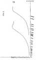
- The above tacts are clearly demonstrated by the curves A and B of the graphs of Figure 1 hereof which are based on the two-layer theory in the above reference. The curves are continuous with the parts lying to the left and right of the vertical dashed line being read against the left and right scales, respectively. These curves are plots of autoregulation power ratio as a function of frequency of the current applied to the patented devices. The maximum autoregulation power ratio is achieved at 0.6 MHz for a material having a mu of 600, ρ1 = 75
X 10 ohm-cm and a thickness of 1.5X 10⁻³ inch as illustrated in Curve B. In this case, one skin depth is-0.9X 10⁻³ inch and the peak ratio of 162 occurs at a frequency of 600 KHz. As indicated above, the thickness of the high mu layer is 1.5X 10⁻³ inch. Thus, the theoretical optimum thickness is 1.67 times one skin depth thickness below the Curie temperature. - The curve A is for a body having a first lamina of a thickness of 0.5
X 10-3 inch. It is noted that the peak ratio of 160 is attained at 6 MHz, at which frequency the skin depth in the magnetic material is .29X 10 inches. - Difficulty may arise in such devices when the Curie temperature is achieved due to spread of the current and/or magnetic flux into adjacent regions outside of the device, particularly if the device is located close to sensitive electrical components.
- In copending patent application, S.N. 243,777, filed March 16, 1981, a continuation-in-part application of the application from which the aforesaid patent matured, there is described a mechanism for preventing the high frequency field generated in the heated device from radiating into the regions adjacent the device. This effect is accomplished by insuring that the copper or other material of high conductivity is sufficiently thick, several skin depths at the frequency of the source, to prevent such radiation and electrical field activity. This feature is important in many applications of the device such as a soldering iron where electromagnetic fields may induce relatively large currents in sensitive circuit components which may destroy such components.
- As indicated above, the magnetic field in a simple, single layer, i.e., monolithic structure, falls off as e-x so that at three skin depths, the field is 4.9% of maximum, at five skin depths, it is 0.67%, and at ten skin depths, the field is .005% of maximum. For many uses, thicknesses of three skin depths are satisfactory although ten or more may be required with some highly sensitive devices in the vicinity of large heating currents.
- The devices of the patent and application are operative for their intended purposes when connected to a suitable supply, but a drawback is the cost of the high frequency power supply. Where only a very low field may be permitted to radiate from the device, the frequency of the source is preferably maintained quite high, for instance, in the megahertz region, to be able to employ copper or other non-magnetic material having reasonable thicknesses.
- In accordance with the invention of my co-pending application entitled "Autoregulating Electrically Shielded Heater," filed on September 30, 1982, a relatively low frequency constant current source may be employed as a result of fabricating the normally non-magnetic, low resistivity layer from a high permeability, high Curie temperature material. Thus, the device comprises a high permeability, high resistivity first layer adjacent the current return path and a high permeability, preferably low resistivity second layer remote from the return path; the second layer having a higher Curie temperature than the first mentioned layer.
- As used herein, the term "high magnetic permeability" refers to materials having permeabilities greater than paramagnetic materials, i.e., ferromagnetic materials, although permeabilities of 100 or more are preferred for most applications.
- The theory of operation underlying the invention of the aforesaid application filed on September 30, 1982 is that by using a high permeability, high Curie temperature material as the low resistivity layer, the skin depth of the current in this second layer is such as to confine the current to a quite thin layer even at low frequencies thereby essentiall insulating the outer surfaces electrically and magnetically but not thermally with a low resistivity layer of manageable thickness. The second layer is preferably formed of a low resistivity material, but this is not essential.
- An example of a device employing two high mu laminae utilizes a layer of Alloy 42 having a resistivity of about 70-80 micro-ohms-cm, a permeability about 200, and a Curie temperature of approximately 300°C. A second layer is formed of carbon steel having a resistivity of about 10 micro-ohms-cm, a permeability of 1000, and a Curie temperature of about 760°C. The skin depths, using a 60 Hz supply are .1" for Alloy 42 and .025" for carbon steel. An example of a practical 60 Hz heater based on the present invention, may employ a coaxial heater consisting of a .25 inch diameter cylindrical or tubular copper conductor (the "return" conductor), a thin layer (perhaps .002 in thickness) of insulation, followed by the temperature sensitive magnetic alloy having a permeability of 400 and a thickness of 0.1 inch, and finally an outer jacket of steel having a permeability of 1000 and a thickness of 0.1 inch. The overall heater diameter would be a .65 inch. If the heater is used in a situation requiring 5 watts per foot of heater I length for, for instance, protection of a liquid against freezing, the total length of the heater is 1000 feet, the resistance of the heater will be 1.96 ohms. The current will be 50 amperes, and the voltage at the generator end will be 140 volts at temperatures somewhat below the Curie temperature of the temperature sensitive magnetic alloy on the inside of the outer pipe. If there were substantial changes in the electrical resistance due to variations of the thermal load, the required voltage must vary in order'to maintain constant current. Either of these latter supplies provide current at costs considerably less than a constant current supply at 8-20 MHz.
- The power regulation ratios (AR) in such a device; 2:1 to 4:1, are not as high as with the device of the patent with a resistivity difference of about 10:1, but the AR difference may be reduced by using materials of higher and lower resistivities for the low Curie temperature and high Curie temperature materials, respectively. Also, a high mu, relatively low resistivity material such as iron or low carbon steel may be employed to further increase the power regulation ratio.
- Referring to Fig. 2 of the accompanying drawings, Curves A and B are plots of the autoregulating power ratios for the dual magnetic layer apparatus of the copendingapplica- tion. It will be noted again that the autoregulating ratio of the device of the prior patent as depicted by Curve B of Fig. 1 rises to 160 at 7 MHz with a first layer thickness of 0.5
X 10-3 inch and copper as the second layer. As depicted by Curve A of Fig. 2, at 60 Hz with a first layer thickness of .125 inch, a ratio of 1.6 is attained at 60 Hz and a ratio of 4 at 1000 Hz. A ratio of 4 is attained as shown in Curve B of Fig. 2 with a different first layer thickness of .010 at 180 KHz. These ratios are attained with layers of Alloy 42 and carbon steel as previously indicated. - In accordance with the present invention, there is provided an element for an autoregulating heating device comprising:
- a laminated structure having at least a first lamina and a second lamina, both being of a material having a high magnetic permeability,
- said first lamina being of a material having a lower Curie temperature than said second lamina, and
- a low resistance layer in electrical contact with said lamina along their adjacent surfaces.
- Autoregulating power ratios of 6:1 to 7:1 are attained while retaining the ability to utilize low frequency supplies without producing unacceptable levels of field radiation.
- The objects of the invention are achieved by providing a region of high conductivity at the interface of the two members having high permeability of the application filed on September 30, 1982.
- The material in the interface region may be copper, for instance, or other highly conductive material. The material may appear as a separate layer, a sandwich of magnetic, non-magnetic and magnetic material or may be bonded to the high and/or low Curie temperature, ferromagnetic layers at the interface to provide a low resistivity, interface regions
- Typical thicknesses of the sandwich construction at 1 KHz are 0.03" for both the low and high Curie temperature ferromagnetic materials, respectively, and .010 inch for the copper layer.
- In operation, as the Curie temperature of the first layer is approached and its permeability rapidly decreases, the current spreads into the copper layer and into the second magnetic layer. The total resistance of the structure, due to the presence of the copper, drops dramatically providing a high autoregulating ratio. Also, most of the current is confined to the copper layer and only a small percentage penetrates into the second magnetic layer. In consequence, this latter layer need be only 3 to 5 skin depths thick to effect virtually complete shielding of the device. Thus, the object of a large autoregulating power ratio in a relatively small device using a low frequency source is achieved. By low frequency is meant a source in the range of 50 Hz to 10,000 Hz although 50 Hz-8000 Hz is fully adequate.
- With autoregulating ratios of 6:1 and 7:1, the heating variations below and above Curie temperature are quite large so that the apparatus may respond rapidly to .thermal load variations and thus maintain accurate temperature regulation in a small device operating at low frequency.
- The above and still further objects, features and advantages of the present invention will become apparent upon consideration of the following detailed description of one specific embodiment thereof, especially when taken in conjunction with the accompanying drawing, wherein:
- Fig. 1 is a graph comparing the autoregulation ratios versus frequency characteristics of the apparatus of the aforesaid Carter and Krumme patent, for different thicknesses of the magnetic layer.
- Fig. 2 is a graph comparing the autoregulating versus frequency characteristics of the apparatus of my application filed on September 30, 1982 for different thicknesses of the lower Curie temperature material.
- Fig. 3 is a view in cross section of a soldering iron fabricated in accordance with the present invention.
- Fig. 4 is a series of graphs comparing the autoregulating characteristics of the device of the present invention with the devices of the prior patent and the application filed on September 30, 1982.
- Fig. 5 is a series of graphs illustrating characteristics of the power versus temperature characteristics of the apparatus of the present invention in comparison with those of the aforesaid Carter and Krumme patent and my application filed on September 30, 1982.
- Referring now specifically to Fig. 2 of the accompanying drawings, there is illustrated in cross section, a soldering iron tip fabricated in accordance with the present invention. The drawing illustrates an
inner cone 2 of high permeability, high resistivity, low Curie temperature material, some examples of which, with their compositions, permeabilities, resistivities, and Curie temperatures are listed in Table 1 below:
- An
outer cone 4 is formed coaxial with and about thecone 2. Thecone 4 is fabricated from a high permeability, preferably low resistivity and high Curie temperature material, examples of which are set forth in Table 2 below: 
- A
layer 6 of high conductivity material such as copper is interposed betweenlayers layer 6, as previously indicated, may be a separate layer or may be bonded tolayer 2 and/ orlayer 4 along the interface between the layers. - A low resistance, cylindrical rod or
tube 8, copper, for instance, extends along the axis of thecones cones layer 6. In one form of the invention, the apices of thecones small diameter extension 10 of therod 8 which extension is suitably electrically in contact with thelayers cones extension 10 may terminate flush with the narrow end of theouter cone 4. - To complete the Figure, a constant current, a.c.
supply 12 is connected between the center conductor and the large diameter ends of thecones - Upon excitation of the
supply 12, alternating curent flowing in the circuit is confined to the surface of thecone 2 adjacent the return path, i.e., therod 8. The power dissipated 2 is determined by the equation P = I R1 where I is a constant "K" due to the use of the constantcurrent supply 12 and R1 is the resistance of thecone 2 at the frequency of the source. The resistance of thecone 2 is a function of the resistivity of the material and also the cross section of thecone 2 to which the current is confined by skin effect. Specifically, resistance is an inverse function of cross-sectional area so that as the cross section of the cone to which the current is confined decreases, as a result of increase in skin effect, the higher the resistance of thecone 2. - As previously indicated, the formula for skin depth in a monolithic material is

- In the present invention, power supplies of relatively low frequencies, i.e., 60 Hz to 10 Khz, may be employed. In such a case, the effective cross-sectional area of the current path is considerably greater than in the prior art device in which frequencies of 8-20 MHz are employed. For instance, skin depth at 60 Hz of Alloy 42 is 0.125" at a permeability of 300, but is 0.0004" at 8 MHz. Thus, at 60 Hz, the thickness of the Alloy 42 layer is larger and resistance of the optimum laminar structure is less than at 8 MHz. High resistivity materials are preferably employed for the
cone 2 in accordance with the present invention in order to provide the high resistance. below Curie temperature necessary to produce the marked change in resistance at the Curie temperature required to produce the desired change in heating in accordance with the formula P = KR. Specifically, in order to autoregulate temperature, the resistance of the circuit must decrease materially when the Curie temperature of the material ofcone 2 is approached. A power ratio of say, 6 to 1, provides excellent regulation for most purposes and for a soldering iron, ratios of 3 to 1 are perfectly acceptable for substantially all uses. As pointed out in the aforesaid U.S. Patent No. 4,256,945, in a solid, i.e., monolithic material, the ratio of resistance values at a given frequency is a function of permeability and resistivity. 
- Since P does not change appreciably with temperature and falls to 1 at the Curie temperature, a permeability of 200 would lead to a resistance change in solid alloy 42 of √200=14.14 The current in a composite, i.e., laminar, structure is no longer confined to this layer; in fact, a large majority of the current flows in the
cone 4 andlayer 6 at the Curie temperature. Thus, the resistivity of the material of thecone 4 andlayer 6 becomes important. Specifically the resistivity of thelayer 6 must be considered, since being of appreciably lower resistance, the majority of the available, i.e., constant current, will be concentrated in this layer. - In operation, when current is initially applied to the apparatus, the current is confined to the
cone 2 which is, in the example discussed herein, 0.125" thick; this being one skin depth of Alloy 42 at 90 Hz. The device heats until the Curie temperature of the material, about 325°C in the example is approached at which point the permeability decreases and the current begins to spread into thelayer 6 andcone 4. The temperature of the material of thecone 4 is still well below its Curie temperature and the current is confined to thecone 2, thelayer 6, and to a few skin depths of thecone 4 at 90 Hz, i.e., approximately .021". - Referring to Fig. 4 of the accompanying drawings, there are presented plots of the autoregulating power ratios of two and three-layer structures including the present invention. Curve A illustrates performance of the two-layer structure in which the second layer is nonmagnetic. Curve B is also for a two-layer structure, the second layer being magnetic. On Curve A, the first layer has approximately the characteristics of Alloy 42 (µ = 200 and P = 75 microhm-centimeters) and the second layer has the characteristics of copper (P = 1 and P = 2 microhm-centimeters). This structure, which corresponds to U.S. Patent No. 4,256,945 of Carter and Krumme has a higher autoregulation ratio than the structure illustrated by Curve B in which the second layer is magnetic, having a permability of 1000. The second layer in Curve B has the electrical characteristics of low carbon steel (µ= 1000 and e = 10 microhm-centimeters). Curve B is a duplicate of the curve A in Fig. 2 in the frequency range between 50 Hz and 10,000 Hz.
- Curve B describes the performance of two-layer structures in which the second layer is magnetic. In the present invention, as previously indicated, a third layer (layer 6) of highly conductive material such as-copper is placed between these two magnetic layers. Referring to Curve C, when the Curie temperature is reached, the resistance drops by a factor larger than that obtained when two magnetic layers are used (Curve B) and smaller than that obtained when the second layer was non-magnetic (Curve A). Thus, the autoregulation ratio of the present invention falls in the range between Curve A and Curve B.
- An approximate analysis of the situation has been used to calculate the autoregulation power ratio based on the following assumptions:
- 1. That very little current flows in the third, magnetic layer;
- 2. That the thickness of the first layer is nominally one skin depth at temperatures below the Curie temperature; and
- 3. That at temperatures above the Curie temperature, the first two layers are much less than one skin depth thick.
- With these assumptions, the resistance below the Curie temperature is proportional to the resistivity of the first layer, and above the Curie temperature, the current divides between the first and second layers as though they were in electrical parallelism. Thus, for equal thickness, first and second layers and assuming the above first-layer characteristic of Alloy 42 (given above) and a second layer of copper, the resulting autoregulation ratio would be approximately 7 at 60 Hz, if the first layer thickness were .125 inch and the second layer thickness .020 inch. This point is shown in Curve C of Figure 4 which is an estimate of the performance of the apparatus. It is also quite reasonable to suppose that the autoregulation ratio increases to a maximum of 200 = 14.14 at higher frequencies where the thickness of the first layer is several skin depths at temperatures below the Curie point.
- As indicated above, the curves of Fig. 4 are based on a thickness of
layer 2 of 0.125" and a thickness oflayer 6 of 0.020" and a frequency in the range of 50 to 10,000 Hz. This approach was taken to illustrate the ability of the apparatus of the present invention to operate at good autoregulation ratios at frequencies as low as 50 Hz. - Referring again to Fig. 4, as indicated above, Curve C is a plot of autoregulating power ratios for the apparatus of the present invention. It will be noted again that the autoregulating ratio of the device of the prior patent, as depicted by the Curve A in Fig. 1, rises to 162 at 6 MHz with a first layer thickness of 0.5 X 10⁻³ inch and copper as the second layer. As depicted by Curve C in Fig. 4, at 60 Hz, with a first layer thickness of .125 inch and a copper layer of .020 inch, a ratio of 7.5 is attained with a ratio of 12 at 1000 Hz. These ratios are obtained with layers of Alloy 42, copper and carbon steel as previously indicated.
- Greatly improved autoregulation ratios can be achieved operating at higher frequencies with layer thickness tailored to such frequency. At 8,000 Hz in the following example, the skin depth of Alloy 42 with a permeability of 200 is 0.0133" and with a desired thickness of 1.8 skin depths, it is 0.024". The thickness of the copper is still 0.02" and thus, the thickness of the two layers is approximately the same. The current in the two layers, therefore, divides roughly as the inverse of their resistivities and the majority of the current flows in the copper. The autoregulation ratio now becomes about 37.5 as opposed to approximately 14 in the Curve C of Fig. 4.
- The curves of Fig. 5 are referred to; Fig. 5 being a power vs. temperature curve that is of the type illustrated in Fig. 3 of the aforesaid U.S. Patent 4,256,945. Graph A of of Fig. 5 is a plot of Power Dissipated (I2R) vs. Temperature for a uniform, i.e., non-laminar, magnetic conductor.
Equation 1 is applicable, the changes in power level being, namely, a function of the changes of resistivity which are very small and changes in permeability which in the example may vary from 300 to 1. - Graph B is a plot for the device of the aforesaid patent. In this arrangement, the power dissipation below Curie temperature is less than in the non-laminar device of Curve A due to the fact that some of the current flows in the copper which has a markedly lower resistance than the magnetic layer. At or near the Curie temperature, Curve B dips to a very low value due to flow of a majority of the current in the copper. Both resistance and permeability have undergone significant reductions. The overall change in power dissipated in the device of Curve B is thus greater than in the case of the solid magnetic structure.
- Reference is now made to Curve C which is for the device of the copending application filed on September 30, 1982. It is seen that below the Curie temperature the power dissipated by the prior device is less than for Curve A, but more than for Curve B since the resistance ratios dominate. There is little resistance change with temperature for Curve A, but a large change for Curve B. Above the Curie temperature, the permeability ratios dominate, and since one layer of the present device remains magnetic permeability and resistivity do not change as much as in the other two laminated devices and more power is dissipated. Thus, the power dissipation ratio for the present device is not as great as for the monlithic device or for the others. However, the device of Curve C has an advantage of size and cost over the solid conductor device and an advantage of cost over the patented device.
- The performance of the device of the present invention is illustrated by Curve D. This curve shows that below Curie temperature, the power dissipated is less than for a monolithic device but-slightly greater than the device of the prior patent since all of the current that is not confined to
layer 2 is not concentrated inlayer 6. A small part of the current, perhaps 10%, spreads into thelayer 4 which has a higher resistance than copper. Thus, the overall resistance of the device is slightly higher than in the patented device. - Above the Curie temperature, the power dissipated is greater than in the case of the patented device, but considerably less than in the monolithic case and in the device of the copending application. The power dissipated relative to the patented device is greater since the resistivity of
layer 4 is greater than that of copper,layer 6. - Thus, the autoregulation power ratio of the present invention at 60 Hz and the sizes specified falls between 3:1 and 10:1, about 6:1 to 7:1 which is more than adequate for the majority of temperature regulating uses while retaining the low cost= of the low frequency supply. Further, in the apparatus of the copending application filed on September 30; 1982, Curve C; above the Curie temperature of the
layer 2, the current is concentrated in thelayer 4 and its distribution is basically exponential. In the present case, the majority of current is confined to thelayers 2 and 6 (perhaps 90%) and only a relatively small part of the current is found inlayer 4. Thus, thelayer 4 of the present invention may be thinner than thelayer 4 in the copending application by an amount greater than the thickness of the copper layer, without losing any of the desired shielding effect. - In order to provide adequate protection against magnetic radiation and electrical short circuit or drain, the thickness of the
cone 4 must be at least several times the skin depth. At a frequency of 60 Hz, thecone 2, at a mu of 300, may be .125" and thecone 4 may be 3 X .025; the factor .025 being skin depth which is multiplied by 3 to prevent consequential magnetic radiation and current leakage to the surface ofcone 4. In an annular device, all transverse dimensions are multiplied by two, so thicknesses apart from the 0.15 diameter center conductor rod are 2(.125 + .020 + 3 X .025) = 0.440. With a 0.15" diameter center conductor added, the diameter is .590. At 10 KHz, the diameter is 0.10 with a .025" diameter center conductor rod. - It should be noted that the calculations set forth in Figs. 1, 2, 4 and 5 are based on the use of Alloy 42 with permeabilities in the
range 200 to 600 and resistivity of about 75 X 10-6 ohm-cms and carbon steel with a permeability of about 1000 and resistivity of about 10 X 10-6 ohm-cms. The use of these materials has been chosen for the example since they are readily available. Other combinations of materials of Tables I and II may be employed. - The use of the devices of the present invention permits the use of low frequency sources without radiation or harmful electromagnetic energy even in units with small dimensions.
- The
Curves Curve 21 is representative of a lesser heat load thanCurve 19 and equilibrium is achieved at a temperature T1 at the interaction of Curves D and 21. The curves intersect along a steep part of Curve D and thus the temperature variation with load changes is not great. - If, however, the rate of heat dissipation is increased, as represented by
Curve 19, the Curve D is intersected at a point on its characteristic having a low response and the temperature variation is at least from T1 to T2. If this variation exceeds the design parameters of a particular system, the constant current to the device may be increased so that the Curve E now represents the characteristic of the device. Under these conditions, theCurve 19 intersects Curve E along a virtually vertical portion of the Curve and good temperature regulation is again achieved. It is essential, however, that the heat dissipation Curves do not intersect the power vs. temperature curve along the horizontal part of the curve at the right of the Figure since equilibrium would probably not be achieved below destruction temperature. - The results of the present invention are achieved by employing a sandwich of copper between high permeability materials one with low resistivity and the other with a high resistivity. It should be noted that the permeabilities of the two magnetic layers may be the same; the major requirement being that the outer laminate having a higher Curie temperature than the inner laminate.
- Although the invention is disclosed as employed in a soldering iron, it is obviously useful in many fields where low cost, well regulated heating is desired, such as scalpels, deicers for aircraft, etc. Such devices may also be cylindrical such as in Fig. 1 of the aforesaid patent in which case the position of the laminae is reversed, i.e., the lower Curie jtemperature material surrounds the higher Curie point material. Also, the device may be flat as in a scalpel or an elongated- heating element for heating pipes.
- The present invention is not intended to be limited to use with laminated structures only. Non-laminated members in electrical contact with the copper strip will function in the present invention; the uniformity and extent of electrical contact determining the actual performance of such a device.
- The frequency of the supply utilized herein is not restricted to a specific range of frequencies. Operation above the range of 1000 to 5000 Hz increases performance very little unless frequencies sufficiently high to significantly increase the resistance of the first layer are employed. Such frequencies, however, are not normally anticipated in view of the large additional cost of the supplies as a function of improved performance.
- The term "constant current" as employed herein does not mean a current that cannot increase but means a current that obeys the following formula:

- Specifically, in order to autoregulate, the power delivered to the load when the heater exceeds Curie temperature, must be less than the power delivered to the load below Curie temperature. If the current is held invariable, then the best autoregulating ratio is achieved short of controlling the power supply to reduce current. So long, however, as the relationship (2) is maintained, autoregulation is achieved notwithstanding changes in current, the current thereby being sufficiently constant for autoregulation. Thus, when large autoregulating ratios are not required, constraints on the degree of current control may be relaxed thus reducing the cost of the power supply.
- The above equation is derived by analyzing the equation:
- P = (I + ΔI)2 (R + ΔR) where P is power,
differentiating P with respect to R)
and to satisfy the requirements for autoregulation

Equation 2 above.


Claims (11)

Priority Applications (1)
| Application Number | Priority Date | Filing Date | Title |
|---|---|---|---|
| AT83307219TATE34688T1 (en) | 1982-12-01 | 1983-11-25 | SELF-REGULATING ELECTRIC HEATING ELEMENT. |
Applications Claiming Priority (2)
| Application Number | Priority Date | Filing Date | Title |
|---|---|---|---|
| US445862 | 1982-12-01 | ||
| US06/445,862US4752673A (en) | 1982-12-01 | 1982-12-01 | Autoregulating heater |
Publications (2)
| Publication Number | Publication Date |
|---|---|
| EP0110692A1true EP0110692A1 (en) | 1984-06-13 |
| EP0110692B1 EP0110692B1 (en) | 1988-06-01 |
Family
ID=23770491
Family Applications (1)
| Application Number | Title | Priority Date | Filing Date |
|---|---|---|---|
| EP83307219AExpiredEP0110692B1 (en) | 1982-12-01 | 1983-11-25 | Autoregulating electric heater |
Country Status (7)
| Country | Link |
|---|---|
| US (1) | US4752673A (en) |
| EP (1) | EP0110692B1 (en) |
| JP (1) | JPS59146181A (en) |
| AT (1) | ATE34688T1 (en) |
| CA (1) | CA1216900A (en) |
| DE (1) | DE3376810D1 (en) |
| ES (1) | ES527652A0 (en) |
Cited By (7)
| Publication number | Priority date | Publication date | Assignee | Title |
|---|---|---|---|---|
| EP0130671A3 (en)* | 1983-05-26 | 1986-12-17 | Metcal Inc. | Multiple temperature autoregulating heater |
| EP0180301A3 (en)* | 1984-10-30 | 1987-11-11 | Metcal Inc. | High efficiency autoregulating heater |
| EP0250094A1 (en)* | 1986-06-10 | 1987-12-23 | Metcal Inc. | High power self-regulating heater |
| EP0252719B1 (en)* | 1986-07-07 | 1992-11-11 | Chisso Engineering CO. LTD. | Electric fluid heater |
| US5480397A (en)* | 1992-05-01 | 1996-01-02 | Hemostatic Surgery Corporation | Surgical instrument with auto-regulating heater and method of using same |
| US5480398A (en)* | 1992-05-01 | 1996-01-02 | Hemostatic Surgery Corporation | Endoscopic instrument with disposable auto-regulating heater |
| US5593406A (en)* | 1992-05-01 | 1997-01-14 | Hemostatic Surgery Corporation | Endoscopic instrument with auto-regulating heater and method of using same |
Families Citing this family (62)
| Publication number | Priority date | Publication date | Assignee | Title |
|---|---|---|---|---|
| US5189271A (en)* | 1982-12-01 | 1993-02-23 | Metcal, Inc. | Temperature self-regulating induction apparatus |
| US4852252A (en)* | 1988-11-29 | 1989-08-01 | Amp Incorporated | Method of terminating wires to terminals |
| US4995838A (en)* | 1988-11-29 | 1991-02-26 | Amp Incorporated | Electrical terminal and method of making same |
| US4987283A (en)* | 1988-12-21 | 1991-01-22 | Amp Incorporated | Methods of terminating and sealing electrical conductor means |
| US5025128A (en)* | 1988-12-02 | 1991-06-18 | Metcal, Inc. | Rivet with integral heater |
| US5064978A (en)* | 1989-06-30 | 1991-11-12 | Amp Incorporated | Assembly with self-regulating temperature heater perform for terminating conductors and insulating the termination |
| US5007574A (en)* | 1989-09-14 | 1991-04-16 | Metcal, Inc. | Desoldering device |
| US5134265A (en)* | 1990-02-16 | 1992-07-28 | Metcal, Inc. | Rapid heating, uniform, highly efficient griddle |
| US5227597A (en)* | 1990-02-16 | 1993-07-13 | Electric Power Research Institute | Rapid heating, uniform, highly efficient griddle |
| WO1992017121A1 (en)* | 1991-04-05 | 1992-10-15 | Metcal, Inc. | Instrument for cutting, coagulating and ablating tissue |
| US5329085A (en)* | 1992-08-05 | 1994-07-12 | Metcal, Inc. | Temperature self regulating heaters and soldering irons |
| US5964759A (en)* | 1992-10-27 | 1999-10-12 | Ortho Development Corporation | Electroconvergent cautery system |
| US5911898A (en)* | 1995-05-25 | 1999-06-15 | Electric Power Research Institute | Method and apparatus for providing multiple autoregulated temperatures |
| AU5836701A (en) | 2000-04-24 | 2001-11-07 | Shell Int Research | In situ recovery of hydrocarbons from a kerogen-containing formation |
| US6929067B2 (en) | 2001-04-24 | 2005-08-16 | Shell Oil Company | Heat sources with conductive material for in situ thermal processing of an oil shale formation |
| AU2002360301B2 (en) | 2001-10-24 | 2007-11-29 | Shell Internationale Research Maatschappij B.V. | In situ thermal processing and upgrading of produced hydrocarbons |
| AU2003285008B2 (en) | 2002-10-24 | 2007-12-13 | Shell Internationale Research Maatschappij B.V. | Inhibiting wellbore deformation during in situ thermal processing of a hydrocarbon containing formation |
| WO2004097159A2 (en) | 2003-04-24 | 2004-11-11 | Shell Internationale Research Maatschappij B.V. | Thermal processes for subsurface formations |
| ATE392534T1 (en) | 2004-04-23 | 2008-05-15 | Shell Int Research | PREVENTION OF RETURN IN A HEATED COUNTER OF AN IN-SITU CONVERSION SYSTEM |
| US7500528B2 (en) | 2005-04-22 | 2009-03-10 | Shell Oil Company | Low temperature barrier wellbores formed using water flushing |
| KR101434259B1 (en) | 2005-10-24 | 2014-08-27 | 쉘 인터내셔날 리써취 마트샤피지 비.브이. | Cogeneration systems and processes for treating hydrocarbon containing formations |
| EP2010755A4 (en) | 2006-04-21 | 2016-02-24 | Shell Int Research | HEATING SEQUENCE OF MULTIPLE LAYERS IN A FORMATION CONTAINING HYDROCARBONS |
| KR20090024171A (en)* | 2006-05-22 | 2009-03-06 | 더 트러스티즈 오브 다트마우스 칼리지 | Complex Shaped Pulse Heat De-Icing |
| GB2461362A (en) | 2006-10-20 | 2010-01-06 | Shell Int Research | Systems and processes for use in treating subsurface formations |
| CN101688442B (en) | 2007-04-20 | 2014-07-09 | 国际壳牌研究有限公司 | Molten salt as a heat transfer fluid for heating a subsurface formation |
| RU2496067C2 (en) | 2007-10-19 | 2013-10-20 | Шелл Интернэшнл Рисерч Маатсхаппий Б.В. | Cryogenic treatment of gas |
| US20090260823A1 (en) | 2008-04-18 | 2009-10-22 | Robert George Prince-Wright | Mines and tunnels for use in treating subsurface hydrocarbon containing formations |
| EP2361343A1 (en) | 2008-10-13 | 2011-08-31 | Shell Oil Company | Using self-regulating nuclear reactors in treating a subsurface formation |
| WO2010118315A1 (en) | 2009-04-10 | 2010-10-14 | Shell Oil Company | Treatment methodologies for subsurface hydrocarbon containing formations |
| US9107666B2 (en) | 2009-04-17 | 2015-08-18 | Domain Surgical, Inc. | Thermal resecting loop |
| US9730749B2 (en) | 2009-04-17 | 2017-08-15 | Domain Surgical, Inc. | Surgical scalpel with inductively heated regions |
| US9265556B2 (en) | 2009-04-17 | 2016-02-23 | Domain Surgical, Inc. | Thermally adjustable surgical tool, balloon catheters and sculpting of biologic materials |
| US9078655B2 (en) | 2009-04-17 | 2015-07-14 | Domain Surgical, Inc. | Heated balloon catheter |
| US9131977B2 (en) | 2009-04-17 | 2015-09-15 | Domain Surgical, Inc. | Layered ferromagnetic coated conductor thermal surgical tool |
| US9469408B1 (en)* | 2009-09-03 | 2016-10-18 | The Boeing Company | Ice protection system and method |
| US8356935B2 (en)* | 2009-10-09 | 2013-01-22 | Shell Oil Company | Methods for assessing a temperature in a subsurface formation |
| US8257112B2 (en) | 2009-10-09 | 2012-09-04 | Shell Oil Company | Press-fit coupling joint for joining insulated conductors |
| US9466896B2 (en)* | 2009-10-09 | 2016-10-11 | Shell Oil Company | Parallelogram coupling joint for coupling insulated conductors |
| US9033042B2 (en) | 2010-04-09 | 2015-05-19 | Shell Oil Company | Forming bitumen barriers in subsurface hydrocarbon formations |
| US8631866B2 (en) | 2010-04-09 | 2014-01-21 | Shell Oil Company | Leak detection in circulated fluid systems for heating subsurface formations |
| US8701768B2 (en) | 2010-04-09 | 2014-04-22 | Shell Oil Company | Methods for treating hydrocarbon formations |
| US8967259B2 (en) | 2010-04-09 | 2015-03-03 | Shell Oil Company | Helical winding of insulated conductor heaters for installation |
| US8939207B2 (en) | 2010-04-09 | 2015-01-27 | Shell Oil Company | Insulated conductor heaters with semiconductor layers |
| US8820406B2 (en) | 2010-04-09 | 2014-09-02 | Shell Oil Company | Electrodes for electrical current flow heating of subsurface formations with conductive material in wellbore |
| US8586866B2 (en) | 2010-10-08 | 2013-11-19 | Shell Oil Company | Hydroformed splice for insulated conductors |
| US8857051B2 (en) | 2010-10-08 | 2014-10-14 | Shell Oil Company | System and method for coupling lead-in conductor to insulated conductor |
| US8943686B2 (en) | 2010-10-08 | 2015-02-03 | Shell Oil Company | Compaction of electrical insulation for joining insulated conductors |
| CA2832295C (en) | 2011-04-08 | 2019-05-21 | Shell Internationale Research Maatschappij B.V. | Systems for joining insulated conductors |
| US8932279B2 (en) | 2011-04-08 | 2015-01-13 | Domain Surgical, Inc. | System and method for cooling of a heated surgical instrument and/or surgical site and treating tissue |
| US9016370B2 (en) | 2011-04-08 | 2015-04-28 | Shell Oil Company | Partial solution mining of hydrocarbon containing layers prior to in situ heat treatment |
| EP2704657A4 (en) | 2011-04-08 | 2014-12-31 | Domain Surgical Inc | IMPEDANCE ADAPTATION CIRCUIT |
| WO2012158722A2 (en) | 2011-05-16 | 2012-11-22 | Mcnally, David, J. | Surgical instrument guide |
| WO2013040255A2 (en) | 2011-09-13 | 2013-03-21 | Domain Surgical, Inc. | Sealing and/or cutting instrument |
| CN104011327B (en) | 2011-10-07 | 2016-12-14 | 国际壳牌研究有限公司 | Using the dielectric properties of insulated wires in subterranean formations to determine the performance of insulated wires |
| JO3141B1 (en) | 2011-10-07 | 2017-09-20 | Shell Int Research | Integral splice for insulated conductors |
| CA2850741A1 (en) | 2011-10-07 | 2013-04-11 | Manuel Alberto GONZALEZ | Thermal expansion accommodation for circulated fluid systems used to heat subsurface formations |
| JO3139B1 (en) | 2011-10-07 | 2017-09-20 | Shell Int Research | Forming insulated conductors using a final reduction step after heat treating |
| JP2015506729A (en) | 2011-12-06 | 2015-03-05 | ドメイン・サージカル,インコーポレーテッド | System and method for controlling power supply to a surgical instrument |
| US10047594B2 (en) | 2012-01-23 | 2018-08-14 | Genie Ip B.V. | Heater pattern for in situ thermal processing of a subsurface hydrocarbon containing formation |
| US10357306B2 (en) | 2014-05-14 | 2019-07-23 | Domain Surgical, Inc. | Planar ferromagnetic coated surgical tip and method for making |
| US10708979B2 (en)* | 2016-10-07 | 2020-07-07 | De-Ice Technologies | Heating a bulk medium |
| CN112955379B (en) | 2018-08-27 | 2024-06-18 | 迪艾斯技术有限公司 | Deicing system |
Citations (4)
| Publication number | Priority date | Publication date | Assignee | Title |
|---|---|---|---|---|
| US3584190A (en)* | 1970-02-27 | 1971-06-08 | Texas Instruments Inc | Self-regulating heat applicator |
| US4256945A (en)* | 1979-08-31 | 1981-03-17 | Iris Associates | Alternating current electrically resistive heating element having intrinsic temperature control |
| WO1982003148A1 (en)* | 1981-03-02 | 1982-09-16 | Ass Iris | Electrically resistive heating element having temperature control |
| WO1982003305A1 (en)* | 1981-03-16 | 1982-09-30 | Ass Iris | Shielded heating element having intrinsic temperature control |
Family Cites Families (14)
| Publication number | Priority date | Publication date | Assignee | Title |
|---|---|---|---|---|
| US1975436A (en)* | 1929-11-08 | 1934-10-02 | Ugine Infra | Method of heating by induction and furnace therefor |
| US2181274A (en)* | 1938-05-11 | 1939-11-28 | Utilities Coordinated Res Inc | Induction heater construction |
| US2918722A (en)* | 1955-11-02 | 1959-12-29 | Nat Standard Co | Electrical communication wire |
| US3218384A (en)* | 1962-03-29 | 1965-11-16 | Int Nickel Co | Temperature-responsive transmission line conductor for de-icing |
| US4207896A (en)* | 1970-08-13 | 1980-06-17 | Shaw Robert F | Surgical instrument having self-regulating dielectric heating of its cutting edge |
| US4185632A (en)* | 1970-08-13 | 1980-01-29 | Shaw Robert F | Surgical instrument having self-regulated electrical skin-depth heating of its cutting edge and method of using the same |
| FR2233685B1 (en)* | 1973-06-12 | 1977-05-06 | Josse Bernard | |
| CA1064561A (en)* | 1974-11-04 | 1979-10-16 | Paul F. Offermann | Method and means for segmentally reducing heat output in heat-tracing pipe |
| US4364390A (en)* | 1975-03-14 | 1982-12-21 | Shaw Robert F | Surgical instrument having self-regulating dielectric heating of its cutting edge and method of using the same |
| US4091813A (en)* | 1975-03-14 | 1978-05-30 | Robert F. Shaw | Surgical instrument having self-regulated electrical proximity heating of its cutting edge and method of using the same |
| JPS5852315B2 (en)* | 1979-02-21 | 1983-11-21 | チッソエンジニアリング株式会社 | Epidermal current heating pipeline |
| JPS5816104B2 (en)* | 1980-03-18 | 1983-03-29 | チツソエンジニアリング株式会社 | Simple induced current heating tube |
| JPS5744826A (en)* | 1980-08-29 | 1982-03-13 | Toshiba Corp | Temperature sensor for detecting abnormal temperature point |
| CA1214815A (en)* | 1982-09-30 | 1986-12-02 | John F. Krumme | Autoregulating electrically shielded heater |
- 1982
- 1982-12-01USUS06/445,862patent/US4752673A/ennot_activeExpired - Fee Related
- 1983
- 1983-11-25EPEP83307219Apatent/EP0110692B1/ennot_activeExpired
- 1983-11-25DEDE8383307219Tpatent/DE3376810D1/ennot_activeExpired
- 1983-11-25ATAT83307219Tpatent/ATE34688T1/ennot_activeIP Right Cessation
- 1983-11-29CACA000442197Apatent/CA1216900A/ennot_activeExpired
- 1983-11-30ESES527652Apatent/ES527652A0/enactiveGranted
- 1983-12-01JPJP58225553Apatent/JPS59146181A/enactiveGranted
Patent Citations (4)
| Publication number | Priority date | Publication date | Assignee | Title |
|---|---|---|---|---|
| US3584190A (en)* | 1970-02-27 | 1971-06-08 | Texas Instruments Inc | Self-regulating heat applicator |
| US4256945A (en)* | 1979-08-31 | 1981-03-17 | Iris Associates | Alternating current electrically resistive heating element having intrinsic temperature control |
| WO1982003148A1 (en)* | 1981-03-02 | 1982-09-16 | Ass Iris | Electrically resistive heating element having temperature control |
| WO1982003305A1 (en)* | 1981-03-16 | 1982-09-30 | Ass Iris | Shielded heating element having intrinsic temperature control |
Cited By (7)
| Publication number | Priority date | Publication date | Assignee | Title |
|---|---|---|---|---|
| EP0130671A3 (en)* | 1983-05-26 | 1986-12-17 | Metcal Inc. | Multiple temperature autoregulating heater |
| EP0180301A3 (en)* | 1984-10-30 | 1987-11-11 | Metcal Inc. | High efficiency autoregulating heater |
| EP0250094A1 (en)* | 1986-06-10 | 1987-12-23 | Metcal Inc. | High power self-regulating heater |
| EP0252719B1 (en)* | 1986-07-07 | 1992-11-11 | Chisso Engineering CO. LTD. | Electric fluid heater |
| US5480397A (en)* | 1992-05-01 | 1996-01-02 | Hemostatic Surgery Corporation | Surgical instrument with auto-regulating heater and method of using same |
| US5480398A (en)* | 1992-05-01 | 1996-01-02 | Hemostatic Surgery Corporation | Endoscopic instrument with disposable auto-regulating heater |
| US5593406A (en)* | 1992-05-01 | 1997-01-14 | Hemostatic Surgery Corporation | Endoscopic instrument with auto-regulating heater and method of using same |
Also Published As
| Publication number | Publication date |
|---|---|
| DE3376810D1 (en) | 1988-07-07 |
| JPS59146181A (en) | 1984-08-21 |
| ATE34688T1 (en) | 1988-06-15 |
| ES8503917A1 (en) | 1985-03-01 |
| ES527652A0 (en) | 1985-03-01 |
| JPH0367315B2 (en) | 1991-10-22 |
| US4752673A (en) | 1988-06-21 |
| EP0110692B1 (en) | 1988-06-01 |
| CA1216900A (en) | 1987-01-20 |
Similar Documents
| Publication | Publication Date | Title |
|---|---|---|
| EP0110692B1 (en) | Autoregulating electric heater | |
| EP0107927B1 (en) | Autoregulating electrically shielded heater | |
| US4695713A (en) | Autoregulating, electrically shielded heater | |
| US4717814A (en) | Slotted autoregulating heater | |
| EP0130671A2 (en) | Multiple temperature autoregulating heater | |
| EP0075010B1 (en) | Shielded heating element having intrinsic temperature control | |
| EP0250094B1 (en) | High power self-regulating heater | |
| US4256945A (en) | Alternating current electrically resistive heating element having intrinsic temperature control | |
| EP0428243B1 (en) | Heater straps | |
| US7449663B2 (en) | Inductive heating apparatus and method | |
| EP0180301B1 (en) | High efficiency autoregulating heater | |
| EP0073190B1 (en) | Electrically resistive heating element having temperature control | |
| US5380989A (en) | Inductive heating element with magnetic and thermistor materials |
Legal Events
| Date | Code | Title | Description |
|---|---|---|---|
| PUAI | Public reference made under article 153(3) epc to a published international application that has entered the european phase | Free format text:ORIGINAL CODE: 0009012 | |
| AK | Designated contracting states | Designated state(s):AT BE CH DE FR GB IT LI LU NL SE | |
| 17P | Request for examination filed | Effective date:19840801 | |
| 17Q | First examination report despatched | Effective date:19860813 | |
| GRAA | (expected) grant | Free format text:ORIGINAL CODE: 0009210 | |
| AK | Designated contracting states | Kind code of ref document:B1 Designated state(s):AT BE CH DE FR GB IT LI LU NL SE | |
| PG25 | Lapsed in a contracting state [announced via postgrant information from national office to epo] | Ref country code:AT Effective date:19880601 | |
| REF | Corresponds to: | Ref document number:34688 Country of ref document:AT Date of ref document:19880615 Kind code of ref document:T | |
| REF | Corresponds to: | Ref document number:3376810 Country of ref document:DE Date of ref document:19880707 | |
| ITF | It: translation for a ep patent filed | ||
| ET | Fr: translation filed | ||
| PG25 | Lapsed in a contracting state [announced via postgrant information from national office to epo] | Ref country code:LU Free format text:LAPSE BECAUSE OF NON-PAYMENT OF DUE FEES Effective date:19881130 | |
| PLBE | No opposition filed within time limit | Free format text:ORIGINAL CODE: 0009261 | |
| STAA | Information on the status of an ep patent application or granted ep patent | Free format text:STATUS: NO OPPOSITION FILED WITHIN TIME LIMIT | |
| 26N | No opposition filed | ||
| PGFP | Annual fee paid to national office [announced via postgrant information from national office to epo] | Ref country code:SE Payment date:19911127 Year of fee payment:9 Ref country code:CH Payment date:19911127 Year of fee payment:9 | |
| ITTA | It: last paid annual fee | ||
| PG25 | Lapsed in a contracting state [announced via postgrant information from national office to epo] | Ref country code:SE Effective date:19921126 | |
| PG25 | Lapsed in a contracting state [announced via postgrant information from national office to epo] | Ref country code:LI Effective date:19921130 Ref country code:CH Effective date:19921130 | |
| REG | Reference to a national code | Ref country code:CH Ref legal event code:PL | |
| EUG | Se: european patent has lapsed | Ref document number:83307219.2 Effective date:19930610 | |
| PGFP | Annual fee paid to national office [announced via postgrant information from national office to epo] | Ref country code:GB Payment date:19971125 Year of fee payment:15 | |
| PGFP | Annual fee paid to national office [announced via postgrant information from national office to epo] | Ref country code:FR Payment date:19971128 Year of fee payment:15 | |
| PGFP | Annual fee paid to national office [announced via postgrant information from national office to epo] | Ref country code:NL Payment date:19971223 Year of fee payment:15 | |
| PGFP | Annual fee paid to national office [announced via postgrant information from national office to epo] | Ref country code:BE Payment date:19980115 Year of fee payment:15 | |
| PG25 | Lapsed in a contracting state [announced via postgrant information from national office to epo] | Ref country code:GB Free format text:LAPSE BECAUSE OF NON-PAYMENT OF DUE FEES Effective date:19981125 | |
| PG25 | Lapsed in a contracting state [announced via postgrant information from national office to epo] | Ref country code:BE Free format text:LAPSE BECAUSE OF NON-PAYMENT OF DUE FEES Effective date:19981130 | |
| PGFP | Annual fee paid to national office [announced via postgrant information from national office to epo] | Ref country code:DE Payment date:19981207 Year of fee payment:16 | |
| BERE | Be: lapsed | Owner name:METCAL INC. Effective date:19981130 | |
| PG25 | Lapsed in a contracting state [announced via postgrant information from national office to epo] | Ref country code:NL Free format text:LAPSE BECAUSE OF NON-PAYMENT OF DUE FEES Effective date:19990601 | |
| GBPC | Gb: european patent ceased through non-payment of renewal fee | Effective date:19981125 | |
| PG25 | Lapsed in a contracting state [announced via postgrant information from national office to epo] | Ref country code:FR Free format text:LAPSE BECAUSE OF NON-PAYMENT OF DUE FEES Effective date:19990730 | |
| NLV4 | Nl: lapsed or anulled due to non-payment of the annual fee | Effective date:19990601 | |
| REG | Reference to a national code | Ref country code:FR Ref legal event code:ST | |
| PG25 | Lapsed in a contracting state [announced via postgrant information from national office to epo] | Ref country code:DE Free format text:LAPSE BECAUSE OF NON-PAYMENT OF DUE FEES Effective date:20000901 |