EP0108584B1 - Syringes - Google Patents
SyringesDownload PDFInfo
- Publication number
- EP0108584B1 EP0108584B1EP83306613AEP83306613AEP0108584B1EP 0108584 B1EP0108584 B1EP 0108584B1EP 83306613 AEP83306613 AEP 83306613AEP 83306613 AEP83306613 AEP 83306613AEP 0108584 B1EP0108584 B1EP 0108584B1
- Authority
- EP
- European Patent Office
- Prior art keywords
- barrel
- syringe
- piston
- tube
- actuating assembly
- Prior art date
- Legal status (The legal status is an assumption and is not a legal conclusion. Google has not performed a legal analysis and makes no representation as to the accuracy of the status listed.)
- Expired
Links
- 239000000463materialSubstances0.000claimsdescription19
- 230000000295complement effectEffects0.000claimsdescription4
- 238000006073displacement reactionMethods0.000description16
- 229920003023plasticPolymers0.000description3
- 239000004033plasticSubstances0.000description3
- 238000007789sealingMethods0.000description3
- 239000002639bone cementSubstances0.000description1
- 239000003814drugSubstances0.000description1
- 230000000694effectsEffects0.000description1
- 239000002184metalSubstances0.000description1
- 230000004048modificationEffects0.000description1
- 238000012986modificationMethods0.000description1
- 239000011345viscous materialSubstances0.000description1
Images
Classifications
- A—HUMAN NECESSITIES
- A61—MEDICAL OR VETERINARY SCIENCE; HYGIENE
- A61B—DIAGNOSIS; SURGERY; IDENTIFICATION
- A61B17/00—Surgical instruments, devices or methods
- A61B17/56—Surgical instruments or methods for treatment of bones or joints; Devices specially adapted therefor
- A61B17/58—Surgical instruments or methods for treatment of bones or joints; Devices specially adapted therefor for osteosynthesis, e.g. bone plates, screws or setting implements
- A61B17/88—Osteosynthesis instruments; Methods or means for implanting or extracting internal or external fixation devices
- A61B17/8802—Equipment for handling bone cement or other fluid fillers
- A61B17/8805—Equipment for handling bone cement or other fluid fillers for introducing fluid filler into bone or extracting it
- A61B17/8825—Equipment for handling bone cement or other fluid fillers for introducing fluid filler into bone or extracting it characterised by syringe details
- A—HUMAN NECESSITIES
- A61—MEDICAL OR VETERINARY SCIENCE; HYGIENE
- A61B—DIAGNOSIS; SURGERY; IDENTIFICATION
- A61B17/00—Surgical instruments, devices or methods
- A61B17/56—Surgical instruments or methods for treatment of bones or joints; Devices specially adapted therefor
- A61B17/58—Surgical instruments or methods for treatment of bones or joints; Devices specially adapted therefor for osteosynthesis, e.g. bone plates, screws or setting implements
- A61B17/88—Osteosynthesis instruments; Methods or means for implanting or extracting internal or external fixation devices
- A61B17/8802—Equipment for handling bone cement or other fluid fillers
- A61B17/8805—Equipment for handling bone cement or other fluid fillers for introducing fluid filler into bone or extracting it
- A61B17/8822—Equipment for handling bone cement or other fluid fillers for introducing fluid filler into bone or extracting it characterised by means facilitating expulsion of fluid from the introducer, e.g. a screw pump plunger, hydraulic force transmissions, application of vibrations or a vacuum
- B—PERFORMING OPERATIONS; TRANSPORTING
- B05—SPRAYING OR ATOMISING IN GENERAL; APPLYING FLUENT MATERIALS TO SURFACES, IN GENERAL
- B05C—APPARATUS FOR APPLYING FLUENT MATERIALS TO SURFACES, IN GENERAL
- B05C17/00—Hand tools or apparatus using hand held tools, for applying liquids or other fluent materials to, for spreading applied liquids or other fluent materials on, or for partially removing applied liquids or other fluent materials from, surfaces
- B05C17/005—Hand tools or apparatus using hand held tools, for applying liquids or other fluent materials to, for spreading applied liquids or other fluent materials on, or for partially removing applied liquids or other fluent materials from, surfaces for discharging material from a reservoir or container located in or on the hand tool through an outlet orifice by pressure without using surface contacting members like pads or brushes
- B05C17/01—Hand tools or apparatus using hand held tools, for applying liquids or other fluent materials to, for spreading applied liquids or other fluent materials on, or for partially removing applied liquids or other fluent materials from, surfaces for discharging material from a reservoir or container located in or on the hand tool through an outlet orifice by pressure without using surface contacting members like pads or brushes with manually mechanically or electrically actuated piston or the like
- B05C17/0116—Hand tools or apparatus using hand held tools, for applying liquids or other fluent materials to, for spreading applied liquids or other fluent materials on, or for partially removing applied liquids or other fluent materials from, surfaces for discharging material from a reservoir or container located in or on the hand tool through an outlet orifice by pressure without using surface contacting members like pads or brushes with manually mechanically or electrically actuated piston or the like characterised by the piston driving means
- B05C17/012—Stepwise advancing mechanism, e.g. pawl and ratchets
- B05C17/0123—Lever actuated
- A—HUMAN NECESSITIES
- A61—MEDICAL OR VETERINARY SCIENCE; HYGIENE
- A61F—FILTERS IMPLANTABLE INTO BLOOD VESSELS; PROSTHESES; DEVICES PROVIDING PATENCY TO, OR PREVENTING COLLAPSING OF, TUBULAR STRUCTURES OF THE BODY, e.g. STENTS; ORTHOPAEDIC, NURSING OR CONTRACEPTIVE DEVICES; FOMENTATION; TREATMENT OR PROTECTION OF EYES OR EARS; BANDAGES, DRESSINGS OR ABSORBENT PADS; FIRST-AID KITS
- A61F2250/00—Special features of prostheses classified in groups A61F2/00 - A61F2/26 or A61F2/82 or A61F9/00 or A61F11/00 or subgroups thereof
- A61F2250/0058—Additional features; Implant or prostheses properties not otherwise provided for
- A61F2250/0071—Additional features; Implant or prostheses properties not otherwise provided for breakable or frangible
- B—PERFORMING OPERATIONS; TRANSPORTING
- B05—SPRAYING OR ATOMISING IN GENERAL; APPLYING FLUENT MATERIALS TO SURFACES, IN GENERAL
- B05C—APPARATUS FOR APPLYING FLUENT MATERIALS TO SURFACES, IN GENERAL
- B05C17/00—Hand tools or apparatus using hand held tools, for applying liquids or other fluent materials to, for spreading applied liquids or other fluent materials on, or for partially removing applied liquids or other fluent materials from, surfaces
- B05C17/005—Hand tools or apparatus using hand held tools, for applying liquids or other fluent materials to, for spreading applied liquids or other fluent materials on, or for partially removing applied liquids or other fluent materials from, surfaces for discharging material from a reservoir or container located in or on the hand tool through an outlet orifice by pressure without using surface contacting members like pads or brushes
- B05C17/00576—Hand tools or apparatus using hand held tools, for applying liquids or other fluent materials to, for spreading applied liquids or other fluent materials on, or for partially removing applied liquids or other fluent materials from, surfaces for discharging material from a reservoir or container located in or on the hand tool through an outlet orifice by pressure without using surface contacting members like pads or brushes characterised by the construction of a piston as pressure exerting means, or of the co-operating container
Definitions
- This inventionis concerned with improvements in and relating to syringes, particularly to syringes for use in medicine for applying more or less viscous materials, such as bone cements, to a desired site.
- such a syringecomprises a barrel for containing material to be dispensed, a delivery tube or nozzle attached to one end of the barrel, a piston movably mounted in the barrel for forcing material contained in the barrel from the barrel to and through the delivery tube, and means for actuating the piston.
- syringesmay have a disposable barrel, piston and delivery tube since it is thereby possible to provide these elements of the syringe, which come into contact with the material to be dispensed, in a pre-sterilized form. It is with this form of syringe that the present invention is concerned.
- a syringecomprising a body member detachably secured to one end of a syringe barrel provided at its other end with a delivery tube and containing a movable piston member, a rod-like piston actuating assembly movably mounted in the body member, and means for moving the piston actuating assembly towards said other end of the syringe barrel to discharge the contents of the barrel; characterized in that the syringe barrel is provided with a generally conical end cap, the piston member is substantially complementary to the interior of the end cap and has a central yieldable pressure portion, and the piston actuating assembly comprises a tube generally coaxial with the syringe barrel and a bar movably mounted within the tube, so that upon actuation of the means for moving the piston actuating assembly said tube is first moved to move the piston member to said other end of the barrel and the said bar is then moved to pierce the central portion of the piston member and to pass through the piston into the delivery tube, i.e. so
- the body member of the syringewill be generally provided with a handle laterally of the barrel/piston actuating assembly axis and the means for moving the piston actuating assembly is conveniently operated by means of a pivoted lever arranged so that it may be moved by squeezing or pulling the lever towards the handle.
- the tube member of the piston actuating assemblyis conveniently moved by means of a rack and pawl arrangement, and the tube being provided with suitable grooves to form the rack.
- the means for moving the rod in the piston actuating assemblymay conveniently take the form of a rack and pawl arrangement.
- the barrelis connected to the delivery tube by means of an end cap detachably secured to the distal end of the barrel and to which the delivery tube is also detachably secured.
- the barrel, piston delivery tube and end-capare of a disposable nature, to enable them to be presented in a pre-sterilized form.
- the rod in the piston actuating meansmay, in accordance with one embodiment of the invention, also be disposable and, in another embodiment of the invention, is a reusable item.
- a syringe in accordance with the inventioncomprises a body member 1 having an integrally formed handle 2.
- a syringe barrel 3is detachably secured to body member 1 by a snap fit between an external annular ring 4 formed at the proximal end of barrel 3 engaging in an annular recess 5 in the forward end (the left-hand end as shown in the drawing) of body member 1.
- barrel member 3is conveniently formed of plastics material and is disposable.
- An end cap 6is removably secured to the distal end of the barrel 3.
- End cap 6comprises a cylindrical portion 7 connected via a truncated conical portion 8 to a nozzle member 9 and is detachably secured to barrel 3 by means of cooperating screw threads on the outside of the distal end of barrel 3 and the inside of cylindrical portion 7 of end cap 6.
- the cooperating threadsare of the quick acting (rapidly translating) type.
- the latteris provided, at its distal end, with a deformable annular lip 10. (A similar sealing effect may be obtained by employing a separate sealing ring, such as an O-ring, or by providing an appropriately located sealing lip on the inner surface of end cap 6).
- a delivery tube 11(see Figure 2) is push-fitted over the outside of delivery nozzle 9 to complete the assembly.
- a piston 12is mounted within barrel 3 and, as shown in the drawings, comprises an annular collar 13 integrally formed with truncated conical web 14 the central portion 15 of which is weakened in comparison with the remainder of the web, i.e. is of reduced thickness.
- the pistonmay take other forms, e.g. may be generally flat, but it is generally desirable that it be provided with a central weakened portion).
- an assembly for actuating piston 12comprising a tubular member 16 having a head 17 for engagement with the rearward facing wall of web 14 of piston 12 and, at its other end, a stop member 18.
- actuating rod 20Mounted within tube 16 are displacement bar 19 and, rearwardly thereof, actuating rod 20.
- An actuating lever 21is pivotably mounted within body member 1 and is provided at its upper end with a spring loaded pawl 22 adapted to engage in transverse grooves 23 formed in the lower surface of tube 16 and forming the teeth of a rack, whereby when actuating lever 21 is closed towards handle 2, pawl 22 engages in a groove 23 so as to move tube 16 forwards (i.e. to the left as shown in the drawing).
- a holding pawl 24is mounted in body member 1 rearwardly of actuating lever 21 to engage with a groove 23 in tube 16 to hold the tube in a fixed position when actuating lever 1 is allowed to return to its forward position under the action of a return spring 25.
- actuating lever 21is reciprocated by the user of the syringe so that tube 16 advances through the body member 1 and, in engagement with piston 12, forces material contained in the barrel through nozzle 9 into a delivery tube 11.
- the apparatusis so constructed and arranged that when stop member 18 of tube 16 abuts the rear face of body member 1, piston 12 has reached the end of its possible travel within barrel 3.
- the rear part of tube 16is provided with a downwardly facing cutout portion 26 so that when, as described above, tube 16 has reached the limit of its travel pawl 22 engages with grooves formed in the lower surface of actuating rod 20. (In order to assist in engagement of pawl 22 with the grooves formed in the lower face of rod 20 the latter is urged downwardly towards the bottom of tube 16 by means of a leaf spring 27).
- actuating lever 21will force actuating rod 20 forwards and, with it, displacement bar 19 so as to pierce the weakened portion 15 of piston 12 and, to this end, displacement bar 19 is conveniently provided with a tapered or pointed head 28.
- displacement bar 19Once displacement bar 19 has pierced piston 12 it then passes, with continued operation of actuating lever 21, through nozzle 9 and into a delivery tube 11 attached thereto, thereby to displace remaining material from the nozzle 9 and delivery tube 11.
- the disposable elements of the syringenamely the barrel 3, piston 12, end cap 6, delivery tube 11 and displacement bar 19 may be removed from the body member 1 and suitably disposed of.
- the tube 16 and actuating rod 20are rotated so that pawls 22 and 24 no longer engage with the grooves therein and they are then manually pulled back to the position shown in Figure 1.
- barrel member 3should first be filled with the material to be dispensed and this is suitably achieved by pouring the material to be dispensed into the barrel member 3, with piston 12 in position and without end cap 6 fitted, via a disposable funnel 29 (see Figure 3 of the drawings).
- end cap 6is fitted followed by the delivery tube 11 and, to assist in this operation, funnel 29 may be inverted to act as a support or stand for barrel 3.
- the barrel 6, piston 12, end cap 6, delivery tube 11 and displacement bar 19are all disposable, that is they are disposed of after use and not reused.
- all these componentsmay be made of sterilisable plastics materials and may be supplied to the user in a presterilised form in a suitable sterilised package.
- the remainder of the components of the syringeare reusable and may be constructed of appropriate materials and are preferably formed of heat sterilisable materials, suitably of metal or heat sterilisable plastics.
- the displacement bar 19is a disposable item.
- the actuating rod and displacement barare formed integrally so that the displacement bar is not disposable.
- the displacement bar/actuating rod assemblymay simply take the form of an elongate rod formed, in principle, by joining the abutting ends of the displacement bar and the actuating rod.
- the assemblyis somewhat shorter than the combined assembly shown in Figure 1 and is substantially wholly contained within the tube 16.
- piston tube 16is provided with two cut-outs: one, at the rear of the tube, is so positioned that when stop 18 abuts body 1, fixed pawl 24 is able to pass through it.
- the cut- outis sufficiently wide to allow tube 16 to be turned about its axis to disengage the driving pawl 22.
- a longitudinally extending slotconnects this cut-out and is so positioned that when the head 17 of tube 16 abuts the body, when the tube is drawn to the rear, then tube 16 may be turned about its axis to re-engage pawl 22.
- the fixed pawl 24is of a width capable of fitting within the interconnecting slot.
- pawl 22When pawl 22 passes through the rearward slot, it engages with an annular groove in the displacement bar: turning the tube disengages the lever pawl 22 and allows the tube to be drawn to its starting position and re-engage with the lever pawl 22.
- the fixed pawl 24maintains the displacement bar in its position, and by means of a spring loaded detent in the bar, the bar engages with the front of tube 16 after it has been withdrawn. Forward movement of the tube by means of the lever 21 allows the displacement bar to rupture the piston 12 and to pass forward into the delivery tube, thus displacing the material therein.
Landscapes
- Health & Medical Sciences (AREA)
- Orthopedic Medicine & Surgery (AREA)
- Surgery (AREA)
- Life Sciences & Earth Sciences (AREA)
- Engineering & Computer Science (AREA)
- Medical Informatics (AREA)
- Biomedical Technology (AREA)
- Heart & Thoracic Surgery (AREA)
- Nuclear Medicine, Radiotherapy & Molecular Imaging (AREA)
- Molecular Biology (AREA)
- Animal Behavior & Ethology (AREA)
- General Health & Medical Sciences (AREA)
- Public Health (AREA)
- Veterinary Medicine (AREA)
- Mechanical Engineering (AREA)
- Infusion, Injection, And Reservoir Apparatuses (AREA)
Description
- This invention is concerned with improvements in and relating to syringes, particularly to syringes for use in medicine for applying more or less viscous materials, such as bone cements, to a desired site.
- Basically such a syringe comprises a barrel for containing material to be dispensed, a delivery tube or nozzle attached to one end of the barrel, a piston movably mounted in the barrel for forcing material contained in the barrel from the barrel to and through the delivery tube, and means for actuating the piston. Such syringes may have a disposable barrel, piston and delivery tube since it is thereby possible to provide these elements of the syringe, which come into contact with the material to be dispensed, in a pre-sterilized form. It is with this form of syringe that the present invention is concerned.
- One problem which is encountered with conventional syringes of this type is that not all the material placed into the syringe is dispensed since after the piston has been moved the length of the barrel, an appreciable amount of material may remain in the delivery tube which is commonly of some length, for example from 3 to 6 inches (7.5-15 cms). It is an object of the invention to provide a syringe which overcomes this problem.
- It is proposed, in FR-A-2442626, to provide a syringe in which material from a syringe is dispensed in two steps, firstly from the main barrel of the syringe end and then from a delivery tube by means of a secondary piston member operating within the main piston member. Both of these piston members have to be separately operated by hand and it would be desirable to have a syringe capable of simple one-step operation, by the operator, e.g. by a means of a lever assembly as shown in DE-A-2814353.
- According to the invention there is provided a syringe comprising a body member detachably secured to one end of a syringe barrel provided at its other end with a delivery tube and containing a movable piston member, a rod-like piston actuating assembly movably mounted in the body member, and means for moving the piston actuating assembly towards said other end of the syringe barrel to discharge the contents of the barrel; characterized in that the syringe barrel is provided with a generally conical end cap, the piston member is substantially complementary to the interior of the end cap and has a central yieldable pressure portion, and the piston actuating assembly comprises a tube generally coaxial with the syringe barrel and a bar movably mounted within the tube, so that upon actuation of the means for moving the piston actuating assembly said tube is first moved to move the piston member to said other end of the barrel and the said bar is then moved to pierce the central portion of the piston member and to pass through the piston into the delivery tube, i.e. so as to disperse material remaining in delivery tube.
- The body member of the syringe will be generally provided with a handle laterally of the barrel/piston actuating assembly axis and the means for moving the piston actuating assembly is conveniently operated by means of a pivoted lever arranged so that it may be moved by squeezing or pulling the lever towards the handle. The tube member of the piston actuating assembly is conveniently moved by means of a rack and pawl arrangement, and the tube being provided with suitable grooves to form the rack. Similarly, the means for moving the rod in the piston actuating assembly may conveniently take the form of a rack and pawl arrangement.
- In the syringe of the invention, the barrel is connected to the delivery tube by means of an end cap detachably secured to the distal end of the barrel and to which the delivery tube is also detachably secured.
- As noted above, the barrel, piston delivery tube and end-cap (when present) are of a disposable nature, to enable them to be presented in a pre-sterilized form. The rod in the piston actuating means may, in accordance with one embodiment of the invention, also be disposable and, in another embodiment of the invention, is a reusable item.
- In order that the invention may be well understood reference will now be made to the accompanying drawings in which:-
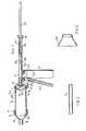
- Figure 1 is a longitudinal section through one embodiment of a syringe in accordance with the invention (with the delivery tube omitted);
- Figure 2 is a longitudinal section through a delivery tube for use with the syringe shown in Figure 1, and
- Figure 3 is a longitudinal section through a funnel for use in filling the barrel of the syringe shown in Figure 1.
- As shown in Figure 1 of the drawings, a syringe in accordance with the invention comprises a body member 1 having an integrally formed
handle 2. A syringe barrel 3 is detachably secured to body member 1 by a snap fit between an externalannular ring 4 formed at the proximal end of barrel 3 engaging in an annular recess 5 in the forward end (the left-hand end as shown in the drawing) of body member 1. As discussed below, barrel member 3 is conveniently formed of plastics material and is disposable. An end cap 6 is removably secured to the distal end of the barrel 3. End cap 6 comprises acylindrical portion 7 connected via a truncated conical portion 8 to anozzle member 9 and is detachably secured to barrel 3 by means of cooperating screw threads on the outside of the distal end of barrel 3 and the inside ofcylindrical portion 7 of end cap 6. Preferably the cooperating threads are of the quick acting (rapidly translating) type. In order to provide for an improved seal between end cap 6 and barrel 3 the latter is provided, at its distal end, with a deformableannular lip 10. (A similar sealing effect may be obtained by employing a separate sealing ring, such as an O-ring, or by providing an appropriately located sealing lip on the inner surface of end cap 6). A delivery tube 11 (see Figure 2) is push-fitted over the outside ofdelivery nozzle 9 to complete the assembly. Apiston 12 is mounted within barrel 3 and, as shown in the drawings, comprises an annular collar 13 integrally formed with truncatedconical web 14 thecentral portion 15 of which is weakened in comparison with the remainder of the web, i.e. is of reduced thickness. (The piston may take other forms, e.g. may be generally flat, but it is generally desirable that it be provided with a central weakened portion). - Mounted within body member 1 is an assembly for actuating
piston 12 and comprising atubular member 16 having ahead 17 for engagement with the rearward facing wall ofweb 14 ofpiston 12 and, at its other end, astop member 18. Mounted withintube 16 aredisplacement bar 19 and, rearwardly thereof, actuatingrod 20. An actuatinglever 21 is pivotably mounted within body member 1 and is provided at its upper end with a spring loaded pawl 22 adapted to engage intransverse grooves 23 formed in the lower surface oftube 16 and forming the teeth of a rack, whereby when actuatinglever 21 is closed towardshandle 2, pawl 22 engages in agroove 23 so as to movetube 16 forwards (i.e. to the left as shown in the drawing). Aholding pawl 24 is mounted in body member 1 rearwardly of actuatinglever 21 to engage with agroove 23 intube 16 to hold the tube in a fixed position when actuating lever 1 is allowed to return to its forward position under the action of areturn spring 25. Thus, in operation, actuatinglever 21 is reciprocated by the user of the syringe so thattube 16 advances through the body member 1 and, in engagement withpiston 12, forces material contained in the barrel throughnozzle 9 into adelivery tube 11. The apparatus is so constructed and arranged that when stopmember 18 oftube 16 abuts the rear face of body member 1,piston 12 has reached the end of its possible travel within barrel 3. - The rear part of
tube 16 is provided with a downwardly facingcutout portion 26 so that when, as described above,tube 16 has reached the limit of its travel pawl 22 engages with grooves formed in the lower surface of actuatingrod 20. (In order to assist in engagement of pawl 22 with the grooves formed in the lower face ofrod 20 the latter is urged downwardly towards the bottom oftube 16 by means of a leaf spring 27). - As a result, further actuation of actuating
lever 21 will force actuatingrod 20 forwards and, with it,displacement bar 19 so as to pierce the weakenedportion 15 ofpiston 12 and, to this end,displacement bar 19 is conveniently provided with a tapered or pointed head 28. Oncedisplacement bar 19 has piercedpiston 12 it then passes, with continued operation of actuatinglever 21, throughnozzle 9 and into adelivery tube 11 attached thereto, thereby to displace remaining material from thenozzle 9 anddelivery tube 11. - When the operation is complete, the disposable elements of the syringe, namely the barrel 3,
piston 12, end cap 6,delivery tube 11 anddisplacement bar 19 may be removed from the body member 1 and suitably disposed of. In order to return the piston actuating assembly to its initial position (i.e. the position as shown in Figure 1 of the drawings) thetube 16 and actuatingrod 20 are rotated so thatpawls 22 and 24 no longer engage with the grooves therein and they are then manually pulled back to the position shown in Figure 1. - In order to assemble a syringe assembly as shown in Figure 1 a
fresh displacement bar 19 is inserted intotube 16 so that its end abuts the end of actuatingrod 20 and a fresh barrel member 3 provided with end cap 6 andpiston 12 is engaged with body member 1. Before doing this, barrel member 3 should first be filled with the material to be dispensed and this is suitably achieved by pouring the material to be dispensed into the barrel member 3, withpiston 12 in position and without end cap 6 fitted, via a disposable funnel 29 (see Figure 3 of the drawings). When the barrel 3 has been filled with the material to be dispensed, end cap 6 is fitted followed by thedelivery tube 11 and, to assist in this operation,funnel 29 may be inverted to act as a support or stand for barrel 3. - As noted above, in the syringe shown in Figure 1 the barrel 6,
piston 12, end cap 6,delivery tube 11 anddisplacement bar 19 are all disposable, that is they are disposed of after use and not reused. Suitably, all these components may be made of sterilisable plastics materials and may be supplied to the user in a presterilised form in a suitable sterilised package. The remainder of the components of the syringe are reusable and may be constructed of appropriate materials and are preferably formed of heat sterilisable materials, suitably of metal or heat sterilisable plastics. - In the syringe particularly described above the
displacement bar 19 is a disposable item. In accordance with another embodiment of the invention, the actuating rod and displacement bar are formed integrally so that the displacement bar is not disposable. In this case the displacement bar/actuating rod assembly may simply take the form of an elongate rod formed, in principle, by joining the abutting ends of the displacement bar and the actuating rod. - In another embodiment of the invention in which the displacement bar and actuating rod are formed integrally, the assembly is somewhat shorter than the combined assembly shown in Figure 1 and is substantially wholly contained within the
tube 16. - In this
modification piston tube 16 is provided with two cut-outs: one, at the rear of the tube, is so positioned that when stop 18 abuts body 1, fixedpawl 24 is able to pass through it. The cut- out is sufficiently wide to allowtube 16 to be turned about its axis to disengage the driving pawl 22. A longitudinally extending slot connects this cut-out and is so positioned that when thehead 17 oftube 16 abuts the body, when the tube is drawn to the rear, thentube 16 may be turned about its axis to re-engage pawl 22. Thefixed pawl 24 is of a width capable of fitting within the interconnecting slot. - When pawl 22 passes through the rearward slot, it engages with an annular groove in the displacement bar: turning the tube disengages the lever pawl 22 and allows the tube to be drawn to its starting position and re-engage with the lever pawl 22. The
fixed pawl 24 maintains the displacement bar in its position, and by means of a spring loaded detent in the bar, the bar engages with the front oftube 16 after it has been withdrawn. Forward movement of the tube by means of thelever 21 allows the displacement bar to rupture thepiston 12 and to pass forward into the delivery tube, thus displacing the material therein.
Claims (5)
Applications Claiming Priority (2)
| Application Number | Priority Date | Filing Date | Title |
|---|---|---|---|
| GB8231600 | 1982-11-05 | ||
| GB8231600 | 1982-11-05 |
Publications (2)
| Publication Number | Publication Date |
|---|---|
| EP0108584A1 EP0108584A1 (en) | 1984-05-16 |
| EP0108584B1true EP0108584B1 (en) | 1988-01-27 |
Family
ID=10534046
Family Applications (1)
| Application Number | Title | Priority Date | Filing Date |
|---|---|---|---|
| EP83306613AExpiredEP0108584B1 (en) | 1982-11-05 | 1983-10-31 | Syringes |
Country Status (6)
| Country | Link |
|---|---|
| US (1) | US4526303A (en) |
| EP (1) | EP0108584B1 (en) |
| JP (1) | JPS59230563A (en) |
| AU (1) | AU569849B2 (en) |
| DE (2) | DE108584T1 (en) |
| ZA (1) | ZA837485B (en) |
Families Citing this family (30)
| Publication number | Priority date | Publication date | Assignee | Title |
|---|---|---|---|---|
| GB8414337D0 (en)* | 1984-06-05 | 1984-07-11 | Rooks R | Pointing |
| DE3534215A1 (en)* | 1985-09-25 | 1987-03-26 | Henke Sass Wolf Gmbh | INJECTION SPRAY GUN WITH ADJUSTABLE PRESSURE LIMIT |
| EP0326551B1 (en)* | 1987-08-15 | 1994-03-16 | Ao-Forschungsinstitut Davos | Hand power tool mechanism |
| DK166691D0 (en)* | 1991-09-30 | 1991-09-30 | Unes As | MULTI-COMPONENT PROJECT |
| DE4219563A1 (en)* | 1992-06-15 | 1993-12-16 | Draenert Klaus | Application system |
| DE9210264U1 (en)* | 1992-07-31 | 1992-11-05 | GFV Verschlußtechnik GmbH & Co., 7297 Alpirsbach | Spray container |
| AT401623B (en)* | 1993-09-27 | 1996-10-25 | Ao Research Inst | MANUAL TOOL |
| US5501374A (en)* | 1994-06-17 | 1996-03-26 | Vital Products, Co. | Device for extruding high viscosity fluid having multiple modes of operation |
| US5755362A (en)* | 1995-02-27 | 1998-05-26 | Minnesota Mining & Manufacturing Co. | Hand-held applicator with force limiting clutch |
| AT406452B (en) | 1996-09-19 | 2000-05-25 | Soraton Sa | MANUAL TOOL |
| ATE289499T1 (en) | 2000-01-18 | 2005-03-15 | Zimmer Gmbh | GUN FOR EXPRESSING BONE CEMENT WITH AN ATTACHABLE CEMENT SYRINGE |
| EP1118313B1 (en)* | 2000-01-18 | 2005-02-23 | Zimmer GmbH | Gun for squeezing out bone cement with a mountable cement syringe |
| DE10064202A1 (en)* | 2000-05-25 | 2001-11-29 | Pajunk Gmbh | Device for applying bone cement and cannula for such a device |
| US6585696B2 (en) | 2000-12-22 | 2003-07-01 | Baxter International, Inc. | Method and apparatus for applying a medically useful multiple component material |
| US7175336B2 (en)* | 2001-01-26 | 2007-02-13 | Depuy Acromed, Inc. | Graft delivery system |
| US6547432B2 (en)* | 2001-07-16 | 2003-04-15 | Stryker Instruments | Bone cement mixing and delivery device for injection and method thereof |
| DE20118100U1 (en)* | 2001-11-07 | 2003-01-09 | Haindl, Hans, Dr.med., 30974 Wennigsen | Pressure injection device for bone cement |
| US6780191B2 (en) | 2001-12-28 | 2004-08-24 | Yacmur Llc | Cannula system |
| US6672489B1 (en)* | 2002-08-28 | 2004-01-06 | Wu-Hsiung Huang | Discharging device for a caulking gun |
| WO2004062713A1 (en)* | 2003-01-16 | 2004-07-29 | Konica Minolta Medical & Graphic, Inc. | Injection auxiliary tool |
| US20050155901A1 (en)* | 2004-01-21 | 2005-07-21 | Krueger John A. | Surgical cement preparation system |
| US10221059B2 (en)* | 2004-03-31 | 2019-03-05 | Ch&I Technologies, Inc. | Refillable material transfer system |
| JP2007215684A (en)* | 2006-02-15 | 2007-08-30 | En Otsuka Pharmaceutical Co Ltd | Administration apparatus and administration container of nutritious composition |
| US8062254B2 (en) | 2008-01-08 | 2011-11-22 | MacLean, LLC | Spring driven adjustable oral syringe |
| WO2011109803A1 (en)* | 2010-03-05 | 2011-09-09 | Medicinelodge, Inc. Dba Imds Co-Innovation | Biologics delivery system |
| BE1020371A3 (en)* | 2012-01-16 | 2013-08-06 | Knaepen Jan Alfons | SPRAY BODY FOR APPLICATION OF A GLUE OR MORTAR FOR MEASUREMENT, A MECHANICAL FORMED BY DRIVES TO WHICH SUCH A BODY IS FITTED AND FILLER FOR FILLING THAT SPRAY BODY. |
| CA2895482A1 (en)* | 2012-12-18 | 2014-06-26 | Novabone Products, Llc | Bioactive glass with ethylene oxide propylene oxide block copolymers |
| JP6567182B2 (en)* | 2016-06-01 | 2019-08-28 | 株式会社ジーシー | Dispenser and dispenser and cartridge |
| CN106073885A (en)* | 2016-07-11 | 2016-11-09 | 周建明 | Pressure bone cement propeller |
| US10154676B1 (en)* | 2017-11-07 | 2018-12-18 | Walter Ready | Food dispenser |
Family Cites Families (16)
| Publication number | Priority date | Publication date | Assignee | Title |
|---|---|---|---|---|
| US1612996A (en)* | 1926-02-23 | 1927-01-04 | Waagbo Herman | Cream-testing device |
| US1976253A (en)* | 1931-08-01 | 1934-10-09 | Tremco Mfg Company | Portable caulking gun |
| US2111582A (en)* | 1936-07-18 | 1938-03-22 | Maintenance Res Ltd | Cartridge for caulking guns |
| DE709563C (en)* | 1939-03-17 | 1941-08-20 | Memmel & Cie Akt Ges | Applicator for cold glue or other liquids |
| US2376662A (en)* | 1943-04-05 | 1945-05-22 | Cohen Max | Toy pistol |
| US2821332A (en)* | 1953-10-19 | 1958-01-28 | William A Sherbondy | Dispensing receptacle for plastic materials |
| US2778541A (en)* | 1955-09-01 | 1957-01-22 | William A Sherbondy | Caulking gun |
| JPS414468Y1 (en)* | 1964-06-23 | 1966-03-15 | ||
| US3381861A (en)* | 1966-07-06 | 1968-05-07 | Roy H. Stein | Gun for applying adhesives to surfaces |
| US3389838A (en)* | 1967-07-20 | 1968-06-25 | Peter J. Morra | Portable apparatus for applying acoustic materials |
| GB1183097A (en)* | 1967-07-20 | 1970-03-04 | Arthur Shaw Company Ltd | Caulking Gun |
| US4030643A (en)* | 1975-12-11 | 1977-06-21 | Voplex Corporation | Contents-conserving plunger for cartridge |
| GB1603102A (en)* | 1977-04-04 | 1981-11-18 | Nat Res Dev | Bone cement preparation in piston extrusion apparatus |
| DE7819584U1 (en)* | 1978-06-30 | 1978-10-12 | Howmedica International, Inc. Zweigniederlassung Kiel, 2301 Schoenkirchen | TUBE-LIKE STORAGE CONTAINER FOR MEDICAL SPRAY DEVICE |
| FR2442626A1 (en)* | 1978-07-07 | 1980-06-27 | Reynaud Marc | Instrument for transferring paste into syringe - has plunger fitting in cylindrical socket with axial bore contg. piston |
| JPS56102237A (en)* | 1980-01-05 | 1981-08-15 | Reinoodo Maruku | Paste material transfer apparatus for filling hollow body |
- 1983
- 1983-10-06ZAZA837485Apatent/ZA837485B/enunknown
- 1983-10-10AUAU20024/83Apatent/AU569849B2/ennot_activeCeased
- 1983-10-26USUS06/545,813patent/US4526303A/ennot_activeExpired - Lifetime
- 1983-10-31DEDE198383306613Tpatent/DE108584T1/enactivePending
- 1983-10-31DEDE8383306613Tpatent/DE3375458D1/ennot_activeExpired
- 1983-10-31EPEP83306613Apatent/EP0108584B1/ennot_activeExpired
- 1983-11-04JPJP58207310Apatent/JPS59230563A/enactiveGranted
Also Published As
| Publication number | Publication date |
|---|---|
| JPS59230563A (en) | 1984-12-25 |
| DE108584T1 (en) | 1984-08-16 |
| AU2002483A (en) | 1984-05-10 |
| JPH0559748B2 (en) | 1993-08-31 |
| ZA837485B (en) | 1984-06-27 |
| DE3375458D1 (en) | 1988-03-03 |
| EP0108584A1 (en) | 1984-05-16 |
| AU569849B2 (en) | 1988-02-25 |
| US4526303A (en) | 1985-07-02 |
Similar Documents
| Publication | Publication Date | Title |
|---|---|---|
| EP0108584B1 (en) | Syringes | |
| US4581022A (en) | Dental syringe | |
| US4371094A (en) | Barrier two part pairing and dispensing cartridge | |
| US3735900A (en) | Dual ingredient storage, intermixing and dispensing storage | |
| EP0744161B1 (en) | Cartridge for dispensing dental material | |
| US4569662A (en) | Bulk cartridge for packaging and dispensing a dental material | |
| JP5431241B2 (en) | Automatic syringe with reset characteristics | |
| EP0225439A1 (en) | Multiple dosage syringe | |
| US4472141A (en) | All purpose dental syringe | |
| EP2330994B1 (en) | Dispensing instrument | |
| DE10229138B4 (en) | Product diverter with piston rod emergency reset | |
| US4232670A (en) | Tube type supply container for medical syringe | |
| JP6563970B2 (en) | Storage mixing system for paste-like cement components and method therefor | |
| US9044545B2 (en) | Needleless injection device | |
| JP6391739B2 (en) | Storage mixing system for paste-like cement components and method therefor | |
| US6652494B1 (en) | Unit dose low viscosity material dispensing system with easy loading | |
| US4432753A (en) | Apparatus for artificial insemination | |
| CA1226190A (en) | Syringes | |
| US20040126733A1 (en) | Dental extruder system | |
| GB2148236A (en) | Expelling contents of collapsible containers | |
| US2890698A (en) | Hypodermic syringe and collapsible cartridge assembly | |
| US6159009A (en) | Dental amalgam carrier with replaceable sleeves and cartridges | |
| US20250214103A1 (en) | Material dispensing system | |
| DE19643664A1 (en) | Process for squeezing paste-like foods contained in containers and device usable thereby | |
| CH694690A5 (en) | Applicator gun for viscous materials has extended housing with trigger actuated linkage for piston to pressurize cartridge held by clamp arm |
Legal Events
| Date | Code | Title | Description |
|---|---|---|---|
| PUAI | Public reference made under article 153(3) epc to a published international application that has entered the european phase | Free format text:ORIGINAL CODE: 0009012 | |
| AK | Designated contracting states | Designated state(s):BE CH DE FR GB LI NL SE | |
| TCNL | Nl: translation of patent claims filed | ||
| EL | Fr: translation of claims filed | ||
| 17P | Request for examination filed | Effective date:19840910 | |
| DET | De: translation of patent claims | ||
| GRAA | (expected) grant | Free format text:ORIGINAL CODE: 0009210 | |
| AK | Designated contracting states | Kind code of ref document:B1 Designated state(s):BE CH DE FR GB LI NL SE | |
| REF | Corresponds to: | Ref document number:3375458 Country of ref document:DE Date of ref document:19880303 | |
| ET | Fr: translation filed | ||
| PLBE | No opposition filed within time limit | Free format text:ORIGINAL CODE: 0009261 | |
| STAA | Information on the status of an ep patent application or granted ep patent | Free format text:STATUS: NO OPPOSITION FILED WITHIN TIME LIMIT | |
| 26N | No opposition filed | ||
| PGFP | Annual fee paid to national office [announced via postgrant information from national office to epo] | Ref country code:NL Payment date:19891031 Year of fee payment:7 | |
| PGFP | Annual fee paid to national office [announced via postgrant information from national office to epo] | Ref country code:CH Payment date:19891110 Year of fee payment:7 | |
| PGFP | Annual fee paid to national office [announced via postgrant information from national office to epo] | Ref country code:BE Payment date:19891115 Year of fee payment:7 | |
| PG25 | Lapsed in a contracting state [announced via postgrant information from national office to epo] | Ref country code:LI Effective date:19901031 Ref country code:CH Effective date:19901031 Ref country code:BE Effective date:19901031 | |
| REG | Reference to a national code | Ref country code:GB Ref legal event code:732 | |
| BERE | Be: lapsed | Owner name:DENTSPLY LTD Effective date:19901031 | |
| PG25 | Lapsed in a contracting state [announced via postgrant information from national office to epo] | Ref country code:NL Effective date:19910501 | |
| NLV4 | Nl: lapsed or anulled due to non-payment of the annual fee | ||
| REG | Reference to a national code | Ref country code:CH Ref legal event code:PL | |
| EAL | Se: european patent in force in sweden | Ref document number:83306613.7 | |
| REG | Reference to a national code | Ref country code:FR Ref legal event code:TP | |
| REG | Reference to a national code | Ref country code:GB Ref legal event code:732E | |
| PGFP | Annual fee paid to national office [announced via postgrant information from national office to epo] | Ref country code:SE Payment date:20011026 Year of fee payment:19 | |
| REG | Reference to a national code | Ref country code:GB Ref legal event code:IF02 | |
| PGFP | Annual fee paid to national office [announced via postgrant information from national office to epo] | Ref country code:GB Payment date:20021030 Year of fee payment:20 | |
| PGFP | Annual fee paid to national office [announced via postgrant information from national office to epo] | Ref country code:DE Payment date:20021031 Year of fee payment:20 | |
| PG25 | Lapsed in a contracting state [announced via postgrant information from national office to epo] | Ref country code:SE Free format text:LAPSE BECAUSE OF NON-PAYMENT OF DUE FEES Effective date:20021101 | |
| PGFP | Annual fee paid to national office [announced via postgrant information from national office to epo] | Ref country code:FR Payment date:20021108 Year of fee payment:20 | |
| EUG | Se: european patent has lapsed | ||
| PG25 | Lapsed in a contracting state [announced via postgrant information from national office to epo] | Ref country code:GB Free format text:LAPSE BECAUSE OF EXPIRATION OF PROTECTION Effective date:20031030 | |
| REG | Reference to a national code | Ref country code:GB Ref legal event code:PE20 |