EP0107238B1 - Nuclear magnetic resonance tomography apparatus - Google Patents
Nuclear magnetic resonance tomography apparatusDownload PDFInfo
- Publication number
- EP0107238B1 EP0107238B1EP83201449AEP83201449AEP0107238B1EP 0107238 B1EP0107238 B1EP 0107238B1EP 83201449 AEP83201449 AEP 83201449AEP 83201449 AEP83201449 AEP 83201449AEP 0107238 B1EP0107238 B1EP 0107238B1
- Authority
- EP
- European Patent Office
- Prior art keywords
- coil
- magnetic resonance
- nuclear magnetic
- sub
- coils
- Prior art date
- Legal status (The legal status is an assumption and is not a legal conclusion. Google has not performed a legal analysis and makes no representation as to the accuracy of the status listed.)
- Expired
Links
Images

Classifications
- G—PHYSICS
- G01—MEASURING; TESTING
- G01R—MEASURING ELECTRIC VARIABLES; MEASURING MAGNETIC VARIABLES
- G01R33/00—Arrangements or instruments for measuring magnetic variables
- G01R33/20—Arrangements or instruments for measuring magnetic variables involving magnetic resonance
- G01R33/28—Details of apparatus provided for in groups G01R33/44 - G01R33/64
- G01R33/32—Excitation or detection systems, e.g. using radio frequency signals
- G01R33/36—Electrical details, e.g. matching or coupling of the coil to the receiver
- G—PHYSICS
- G01—MEASURING; TESTING
- G01R—MEASURING ELECTRIC VARIABLES; MEASURING MAGNETIC VARIABLES
- G01R33/00—Arrangements or instruments for measuring magnetic variables
- G01R33/20—Arrangements or instruments for measuring magnetic variables involving magnetic resonance
- G01R33/28—Details of apparatus provided for in groups G01R33/44 - G01R33/64
- G01R33/32—Excitation or detection systems, e.g. using radio frequency signals
- G01R33/34—Constructional details, e.g. resonators, specially adapted to MR
- G01R33/34046—Volume type coils, e.g. bird-cage coils; Quadrature bird-cage coils; Circularly polarised coils
- G01R33/34069—Saddle coils
- Y—GENERAL TAGGING OF NEW TECHNOLOGICAL DEVELOPMENTS; GENERAL TAGGING OF CROSS-SECTIONAL TECHNOLOGIES SPANNING OVER SEVERAL SECTIONS OF THE IPC; TECHNICAL SUBJECTS COVERED BY FORMER USPC CROSS-REFERENCE ART COLLECTIONS [XRACs] AND DIGESTS
- Y10—TECHNICAL SUBJECTS COVERED BY FORMER USPC
- Y10S—TECHNICAL SUBJECTS COVERED BY FORMER USPC CROSS-REFERENCE ART COLLECTIONS [XRACs] AND DIGESTS
- Y10S505/00—Superconductor technology: apparatus, material, process
- Y10S505/825—Apparatus per se, device per se, or process of making or operating same
- Y10S505/842—Measuring and testing
- Y10S505/843—Electrical
- Y10S505/844—Nuclear magnetic resonance, NMR, system or device
Definitions
- the inventionrelates to a nuclear magnetic resonance tomography apparatus comprising, arranged about an examination space for an object to be measured, a coil system for generating a primary magnetic field and a coil system for generating a pulsed r.f. magnetic field, and also comprising a measurement device for the detection of nuclear magnetic resonance signals generated in an object.
- a nuclear magnetic resonance tomography apparatus of this kindis known from computer- tomographie 1 (1981), pages 2-10.
- an r.f. magnetic fieldis produced by means of an r.f. transmitter coil (for example, as shown in fig. 8b therein) in order to excite nuclear magnetic resonance signals in an object to be examined.
- an r.f. transmitter coilfor example, as shown in fig. 8b therein
- the same coilis used for the measurement of free induction magnetic resonance signals thus generated.
- comparatively strong primary fieldsfor example, up to 0.2 Tesla for resistive magnets and up to 0.5 Tesla for super-conducting magnets.
- the Larmor frequencyfor carrying out measurements, for example, up to approximately 9 MHz for resistive magnets and up to approximately 20 MHz for superconducting magnets, both for proton magnetic resonance signals.
- the nuclear magnetic resonance tomography apparatus in accordance with the inventionis characterized in that the self resonance frequency of the r.f. coil is substantially higher than the highest frequency component of resonance signal which is to be measured.
- the inventionis based on the recognition of the fact that at higher frequencies the exchange of energy in a resonant network between the inductance of (0.5 L i 2 ) and the capacitance (0.5 C V 2 ) formed by the distributed stray capacity of the inductance, is less favourable than in a situation in which the capacitance is formed by an external high-quality capacitor.
- the resonant frequency of the inductance with its own capacitymust be high with respect to the operating frequency (the Larmor frequency). When this condition is satisfied, the quality factor Q can be maintained at a reasonably high level even for high operating frequencies.
- the transmitter/measurement coil of a preferred embodiment of a nuclear magnetic resonance tomography apparatus in accordance with the inventionconsists of a double saddle-shaped coil comprising winding sections which are driven in parallel.
- the effective coil surface areathus remains the same, but the self resonance frequency f(p) becomes substantially higher.
- the wires forming the windings and the connectionsmust be mounted so that they closely adjoin one another. It may be advantageous that the wires should take the form of a flat-tape in the regions where they contact one another.
- Each of the saddle-coil windingscan preferably be divided into four winding sections which can be driven in parallel.
- the wires of each of the winding sectionsare preferably connected together at points which are symmetrically situated with respect to the sub-coils; if necessary, these points are connected to connection points which are symmetrically situated on the connection wires for driving and reading.
- connection pointswhich are symmetrically situated on the connection wires for driving and reading.
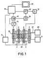
- a nuclear magnetic resonance tomography apparatus as shown in fig. 1comprises magnet coils 2 for generating a steady homogeneous magnetic field, magnet coils 4 for generating a quasi-steady gradient field, a power supply source 6 for the magnet coils 2, and a power supply source 8 for the magnet coils 4.
- a magnet coil 10serves to generate a pulsed r.f. magnetic field, for which purpose it is connected both to an r.f. source 12 and for detecting free induction signals generated by the r.f. field in an object to be measured.
- the coil 10is connected to a signal amplifier 14.
- the signal amplifier 14is connected to a phase-sensitive rectifier 16 which is connected to a central control device 18.
- the central control device 18also controls a modulator 20 for the r.f. source 12, the power supply source 8 for the quasi-steady gradient field, and a monitor 22 for image display.
- a high frequency oscillator 24controls both the modulator 20 for the r.f. source 12 and the phase-sensitive rectifier 16 for processing the measurement signals.
- a cooling device 26 with cooling ducts 27is provided for cooling the magnet coils which generate the primary field.
- Such a cooling devicemay be constructed for water cooling resistive magnets or for liquid helium cooling superconducting magnets.
- the inventioncan be used notably, but not exclusively, for superconducting magnets, because these magnets generate comparatively strong magnetic fields and hence comparatively high magnetic resonance signal frequencies.
- a Faraday cage 28encloses a measurement space in the apparatus and surrounds the transmitter/measurement coil 10, but is situated within the coils 2 and 4 which generate the primary magnetic field in accordance with EP-A-0 105 550 having the priority date 20.09.82 and published on 18.04.84, in the name of Applicant.
- Fig. 2shows diagrammatically a preferred embodiment of a transmitter/measurement coil.
- a coil 30is actually a double saddle-shaped coil and customarily consists of two coil halves 32 and 34.
- the coilis excited by an r.f. source 36 which preferably includes a tuning capacitor 38.
- each of the coil halvesis divided into sub-coils; in this case each half is divided into four sub-coils 40 whose end faces adjoin one another.
- the number of sub-coilswill be chosen to be as small as possible provided that the frequency range extends high enough.
- Each of the sub-coilsis provided with connection points 42 and 44. In this embodiment all the connection points 42 are connected to a power supply line 46, and all the connection points 44 are connected to a power supply line 48.
- connection points of the sub-coils of the second coil half 34are also connected to these power supply lines.
- the source 36excites the sub-coils in parallel, at least with respect to each coil half; in fact, two coil halves are formed in this case which each comprise four sub-coils, with the result that the loss resistances and the inductances are in parallel in the sub-divided situation, so that a coil is obtained which has a higher self resonance frequency; consequently, the quality factor is substantially improved for the relevant high operating frequency.
- the power supply connectionshould preferably be as symmetrical as possible and the coil wires at the sub-coil interconnections should be mounted so that they firmly adjoin one another.
- connection points 42 of the sub-coils 40 of both coil halves 32 and 34 which are provided on an electrically insulating cylinder 50are pair-wise connected to junctions 52 which are symmetrically situated with respect to the sub-coils, the connection points 44 being similarly connected to symmetrically situated junctions 54. Both or several junctions are further connected to respective symmetrically situated connections 56 and 58.
- the power supply source 36 with the tuning capacitor 38is connected across the connections 56 and 58.
- a magnetic resonance induction signal measurement deviceis connected between the terminals 60 and 62.
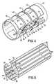
- Fig. 4is a more structural perspective representation of the same coil.
- the sub-coil transition parts 70 of the wire turns on the plastics insulating cylinder 50are arranged as closely as possible against one another; if desired, tape-shaped wire can be used for this purpose.
- Wire portions 72are arranged so that they follow the course of the originally continuous wire as well as possible.
- Wire portions 74are again arranged as near as possible to one another in pairs; this means one for each junction 52 and 54 so that they carry current in opposite directions, the pairs thus formed being situated in an optimally symmetrical arrangement with respect to the relevant sub-coils.
- Wire portions 76 which interconnect the junctionsare again arranged as near as possible to and preferably against one another, at least as far as they form the to and fro current leads of a sub-coil feed.
- connection points 82 and 84are again optimally symmetrically connected to connection points 86 and 88 of the power supply source (not shown) or the measurement device for the r.f. field or the magnetic resonance signals. It is to be noted that there preferably should be no connections in the open end of the coil assembly in order to permit the introduction and removal of objects to be measured.
- This coilcan be arranged on an insulating supporting cylinder in a similar manner to that shown in Figure 4.
- the coilsmay be composed of several conductors (turns) as long as the resonance frequency f(p) resulting from the self capacitance is high with respect to the operating frequency.
- Each of the sub-coilsmay be connected to its own individual read amplifier.
- the read signals therefromcan be processed as a sum signal.
- the quality factor Qis thus increased because the power supply wires can be dispensed with. It is then desirable to construct the transmitter coil and the measurement coil as individual different coils. These coils may then be oriented, for example, transversely with respect to one another.
- the inventionhas been described mainly with reference to proton resonance.
- Protons or hydrogen nucleiare present at a high concentration in biological objects.
- concentration of other nuclei of medical interest, such as phosphorous, sodium and the likeis much lower. Consequently, a substantially smaller resonance signal occurs when resonance measurements are performed thereon in similar circumstances. Therefore, the use of a coil having a high quality factor is important.
- the Larmor frequency for these nucleimay be lower for the same primary field, but in order to obtain a reasonably strong resonance signal it is desirable to have a stronger primary field available for the measurement.
Landscapes
- Physics & Mathematics (AREA)
- Condensed Matter Physics & Semiconductors (AREA)
- General Physics & Mathematics (AREA)
- Magnetic Resonance Imaging Apparatus (AREA)
Description
- The invention relates to a nuclear magnetic resonance tomography apparatus comprising, arranged about an examination space for an object to be measured, a coil system for generating a primary magnetic field and a coil system for generating a pulsed r.f. magnetic field, and also comprising a measurement device for the detection of nuclear magnetic resonance signals generated in an object.
- A nuclear magnetic resonance tomography apparatus of this kind is known from computer- tomographie 1 (1981), pages 2-10. In an apparatus of this kind, an r.f. magnetic field is produced by means of an r.f. transmitter coil (for example, as shown in fig. 8b therein) in order to excite nuclear magnetic resonance signals in an object to be examined. Customarily the same coil is used for the measurement of free induction magnetic resonance signals thus generated. In order to generate sufficiently strong signals, for example, for performing a medical diagnosis on a patient it is necessary to use comparatively strong primary fields of, for example, up to 0.2 Tesla for resistive magnets and up to 0.5 Tesla for super-conducting magnets. Via the known gyromagnetic ratio, this results in an operating frequency (usually referred to as the Larmor frequency) for carrying out measurements, for example, up to approximately 9 MHz for resistive magnets and up to approximately 20 MHz for superconducting magnets, both for proton magnetic resonance signals.
- However, it has been found that in known apparatus a poor signal-to-noise ratio occurs in the measurement signals notably at the high measurement frequencies required for medical diagnosis. Investigations have revealed that this poor ratio is caused mainly by the fact that the quality factor Q of the transmitter/measurement coil decreases as the operating frequency increases as the operating frequency increases so that, for example, at 20 MHz useful measurements are often no longer possible.
- It is the object of the invention to mitigate this drawback; to this end, the nuclear magnetic resonance tomography apparatus in accordance with the invention is characterized in that the self resonance frequency of the r.f. coil is substantially higher than the highest frequency component of resonance signal which is to be measured.
- The invention is based on the recognition of the fact that at higher frequencies the exchange of energy in a resonant network between the inductance of (0.5 L i2) and the capacitance (0.5 C V2) formed by the distributed stray capacity of the inductance, is less favourable than in a situation in which the capacitance is formed by an external high-quality capacitor. This means that the resonant frequency of the inductance with its own capacity must be high with respect to the operating frequency (the Larmor frequency). When this condition is satisfied, the quality factor Q can be maintained at a reasonably high level even for high operating frequencies.
- The transmitter/measurement coil of a preferred embodiment of a nuclear magnetic resonance tomography apparatus in accordance with the invention consists of a double saddle-shaped coil comprising winding sections which are driven in parallel. The effective coil surface area thus remains the same, but the self resonance frequency f(p) becomes substantially higher. In order to prevent an increase of the value of the stray capacitance C(p), the wires forming the windings and the connections must be mounted so that they closely adjoin one another. It may be advantageous that the wires should take the form of a flat-tape in the regions where they contact one another. Each of the saddle-coil windings can preferably be divided into four winding sections which can be driven in parallel. The wires of each of the winding sections are preferably connected together at points which are symmetrically situated with respect to the sub-coils; if necessary, these points are connected to connection points which are symmetrically situated on the connection wires for driving and reading. For electrically screening the axial spaces between the two saddle coils thus formed, each of which may cover an angle of, for example, approximately 120°, for example, a comb-shaped assembly of electrical conductors interconnected at one end only, may be provided in these regions.
- Some preferred embodiments in accordance with the invention will be described in detail hereinafter. Therein:
- Fig. 1 shows a block diagram of a nuclear magnetic resonance tomography apparatus in accordance with the invention,
- Fig. 2 shows a preferred embodiment of an appropriate transmitter/measurement coil;
- Fig. 3 shows a preferred embodiment of such a coil comprising symmetrical connections,
- Fig. 4 is a structural drawing of such a coil, and
- Fig. 5 shows a preferred embodiment of a transmitter/measurement coil with an azimuthal coil subdivision.
- A nuclear magnetic resonance tomography apparatus as shown in fig. 1 comprises
magnet coils 2 for generating a steady homogeneous magnetic field, magnet coils 4 for generating a quasi-steady gradient field, apower supply source 6 for themagnet coils 2, and apower supply source 8 for the magnet coils 4. A magnet coil 10 serves to generate a pulsed r.f. magnetic field, for which purpose it is connected both to an r.f.source 12 and for detecting free induction signals generated by the r.f. field in an object to be measured. For the purpose of detection the coil 10 is connected to asignal amplifier 14. Thesignal amplifier 14 is connected to a phase-sensitive rectifier 16 which is connected to acentral control device 18. Thecentral control device 18 also controls amodulator 20 for the r.f.source 12, thepower supply source 8 for the quasi-steady gradient field, and amonitor 22 for image display. Ahigh frequency oscillator 24 controls both themodulator 20 for the r.f.source 12 and the phase-sensitive rectifier 16 for processing the measurement signals. Acooling device 26 withcooling ducts 27 is provided for cooling the magnet coils which generate the primary field. Such a cooling device may be constructed for water cooling resistive magnets or for liquid helium cooling superconducting magnets. The invention can be used notably, but not exclusively, for superconducting magnets, because these magnets generate comparatively strong magnetic fields and hence comparatively high magnetic resonance signal frequencies. A Faradaycage 28 encloses a measurement space in the apparatus and surrounds the transmitter/measurement coil 10, but is situated within thecoils 2 and 4 which generate the primary magnetic field in accordance with EP-A-0 105 550 having the priority date 20.09.82 and published on 18.04.84, in the name of Applicant. - Fig. 2 shows diagrammatically a preferred embodiment of a transmitter/measurement coil. Such a
coil 30 is actually a double saddle-shaped coil and customarily consists of twocoil halves source 36 which preferably includes atuning capacitor 38. In accordance with the invention, each of the coil halves is divided into sub-coils; in this case each half is divided into foursub-coils 40 whose end faces adjoin one another. The number of sub-coils will be chosen to be as small as possible provided that the frequency range extends high enough. Each of the sub-coils is provided withconnection points connection points 42 are connected to apower supply line 46, and all theconnection points 44 are connected to apower supply line 48. The corresponding connection points of the sub-coils of the second coil half 34 (unreferenced for the sake of clarity) are also connected to these power supply lines. Thesource 36 excites the sub-coils in parallel, at least with respect to each coil half; in fact, two coil halves are formed in this case which each comprise four sub-coils, with the result that the loss resistances and the inductances are in parallel in the sub-divided situation, so that a coil is obtained which has a higher self resonance frequency; consequently, the quality factor is substantially improved for the relevant high operating frequency. For the construction of such a coil it is important that the situation in which the assembly behaves as though it were a single coil should be maintained with respect to each element in an object to be measured, and that the stray capacitance of the coil system should not be increased. Therefore, the power supply connection should preferably be as symmetrical as possible and the coil wires at the sub-coil interconnections should be mounted so that they firmly adjoin one another. - In a preferred embodiment of a coil as shown in fig. 3, therefore, the
connection points 42 of thesub-coils 40 of bothcoil halves cylinder 50 are pair-wise connected tojunctions 52 which are symmetrically situated with respect to the sub-coils, theconnection points 44 being similarly connected to symmetricallysituated junctions 54. Both or several junctions are further connected to respective symmetricallysituated connections 56 and 58. Thepower supply source 36 with thetuning capacitor 38 is connected across theconnections 56 and 58. During the measurement phase a magnetic resonance induction signal measurement device is connected between theterminals - Fig. 4 is a more structural perspective representation of the same coil. In the region of the
sub-coil transition parts 70 of the wire turns on theplastics insulating cylinder 50 are arranged as closely as possible against one another; if desired, tape-shaped wire can be used for this purpose.Wire portions 72 are arranged so that they follow the course of the originally continuous wire as well as possible.Wire portions 74 are again arranged as near as possible to one another in pairs; this means one for eachjunction - Instead of the axial sub-division of coil halves described thus far, the embodiment shown in fig. 5 is sub-divided circumferentially. Each of the coil halves 32 and 34 is sub-divided into six
sub-coils 80, each of which comprises connection points 82 and 84. The connection points are again optimally symmetrically connected to connection points 86 and 88 of the power supply source (not shown) or the measurement device for the r.f. field or the magnetic resonance signals. It is to be noted that there preferably should be no connections in the open end of the coil assembly in order to permit the introduction and removal of objects to be measured. This coil can be arranged on an insulating supporting cylinder in a similar manner to that shown in Figure 4. - Even though so far only one turn of wire has been mentioned for the coils, the coils may be composed of several conductors (turns) as long as the resonance frequency f(p) resulting from the self capacitance is high with respect to the operating frequency.
- Each of the sub-coils may be connected to its own individual read amplifier. The read signals therefrom can be processed as a sum signal. The quality factor Q is thus increased because the power supply wires can be dispensed with. It is then desirable to construct the transmitter coil and the measurement coil as individual different coils. These coils may then be oriented, for example, transversely with respect to one another.
- The invention has been described mainly with reference to proton resonance. Protons or hydrogen nuclei, of course, are present at a high concentration in biological objects. The concentration of other nuclei of medical interest, such as phosphorous, sodium and the like is much lower. Consequently, a substantially smaller resonance signal occurs when resonance measurements are performed thereon in similar circumstances. Therefore, the use of a coil having a high quality factor is important. The Larmor frequency for these nuclei may be lower for the same primary field, but in order to obtain a reasonably strong resonance signal it is desirable to have a stronger primary field available for the measurement.
- Instead of the described circuit comprising a separate amplifier for each of the sub-coils, parallel current control can also be applied. The original signal intensity being maintained, the coil resistance and hence the noise is then reduced, so that a better signal-to-noise ration is obtained.
- For an operating frequency of approximately 20 MHz it has been found that a signal-to-noise ratio improvement of 5 dB can be readily achieved in an apparatus in accordance with the invention.
Claims (9)
Applications Claiming Priority (2)
| Application Number | Priority Date | Filing Date | Title |
|---|---|---|---|
| NL8203934 | 1982-10-12 | ||
| NL8203934ANL8203934A (en) | 1982-10-12 | 1982-10-12 | NUCLEAR SPIN COMMENT. |
Publications (2)
| Publication Number | Publication Date |
|---|---|
| EP0107238A1 EP0107238A1 (en) | 1984-05-02 |
| EP0107238B1true EP0107238B1 (en) | 1986-08-20 |
Family
ID=19840396
Family Applications (1)
| Application Number | Title | Priority Date | Filing Date |
|---|---|---|---|
| EP83201449AExpiredEP0107238B1 (en) | 1982-10-12 | 1983-10-10 | Nuclear magnetic resonance tomography apparatus |
Country Status (6)
| Country | Link |
|---|---|
| US (1) | US4616181A (en) |
| EP (1) | EP0107238B1 (en) |
| JP (1) | JPS5999239A (en) |
| CA (1) | CA1194108A (en) |
| DE (1) | DE3365468D1 (en) |
| NL (1) | NL8203934A (en) |
Families Citing this family (32)
| Publication number | Priority date | Publication date | Assignee | Title |
|---|---|---|---|---|
| JPS6031070A (en)* | 1983-08-01 | 1985-02-16 | Hitachi Ltd | Inspection equipment using nuclear magnetic resonance |
| JPH0634029B2 (en)* | 1984-04-23 | 1994-05-02 | 三菱電機株式会社 | High frequency coil |
| DE8418666U1 (en)* | 1984-06-07 | 1985-10-17 | Siemens AG, 1000 Berlin und 8000 München | Magnetic resonance tomography device |
| FR2567647B1 (en)* | 1984-07-10 | 1987-12-18 | Thomson Cgr | DEVICE FOR CREATING AND / OR RECEIVING AN ALTERNATE MAGNETIC FIELD FOR APPARATUS EXPLOITING NUCLEAR MAGNETIC RESONANCE |
| JPS6129775A (en)* | 1984-07-20 | 1986-02-10 | Mitsubishi Electric Corp | High frequency magnetic field generator/detector |
| NL8402380A (en)* | 1984-07-30 | 1986-02-17 | Philips Nv | NUCLEAR SPIN RESONANCE DEVICE WITH A TRANSMITTER COIL FOR HIGH FREQUENCIES. |
| US4682112A (en)* | 1984-10-10 | 1987-07-21 | Elscint Ltd. | NMR antenna and method for designing the same |
| JPH0616758B2 (en)* | 1984-10-15 | 1994-03-09 | 株式会社東芝 | Magnetic resonance imaging device |
| US4725780A (en)* | 1984-10-19 | 1988-02-16 | Mitsubishi Denki Kabushiki Kaisha | RF field generator and detector |
| DE3576736D1 (en)* | 1984-12-28 | 1990-04-26 | Siemens Ag | DEVICE FOR IMAGING FORK-SHAPED BODY REGIONS BY MEANS OF MAGNETIC RESONANCE. |
| US4721915A (en)* | 1985-03-06 | 1988-01-26 | Siemens Aktiengesellschaft | High frequency antenna system for nuclear magnetic resonance tomography devices |
| FR2583172B1 (en)* | 1985-06-07 | 1987-11-20 | Thomson Cgr | HIGH FREQUENCY ANTENNA FOR APPARATUS FOR MEASURING NUCLEAR MAGNETIC RESONANCE |
| DE3522401A1 (en)* | 1985-06-22 | 1987-01-02 | Bruker Medizintech | SAMPLE HEAD FOR NMR TOMOGRAPHY |
| NL8600730A (en)* | 1986-03-21 | 1987-10-16 | Philips Nv | MAGNETIC RESONANCE DEVICE WITH INTERFERENCE-FREE RF COIL. |
| US4784146A (en)* | 1986-08-14 | 1988-11-15 | University Of Florida | Angled segment receiver coil for NMR imaging of a human head |
| NL8603006A (en)* | 1986-11-27 | 1988-06-16 | Philips Nv | MAGNETIC RESONANCE DEVICE WITH STACKED SURFACE COIL SYSTEM. |
| US4751464A (en)* | 1987-05-04 | 1988-06-14 | Advanced Nmr Systems, Inc. | Cavity resonator with improved magnetic field uniformity for high frequency operation and reduced dielectric heating in NMR imaging devices |
| GB2208937B (en)* | 1987-08-21 | 1992-04-01 | Fuji Electric Co Ltd | High frequency coil |
| JPH01192341A (en)* | 1988-01-29 | 1989-08-02 | Toshiba Corp | magnetic resonance imaging device |
| US4857846A (en)* | 1988-03-31 | 1989-08-15 | The Regents Of The University Of California | Rapid MRI using multiple receivers producing multiply phase-encoded data derived from a single NMR response |
| JP2671364B2 (en)* | 1988-04-05 | 1997-10-29 | 株式会社日立製作所 | Inspection equipment using nuclear magnetic resonance |
| GB8814187D0 (en)* | 1988-06-15 | 1988-07-20 | Mansfield P | Improvements in/relating to surface electrical coil structures |
| DE3938167A1 (en)* | 1988-11-28 | 1990-05-31 | Siemens Ag | GRADIENT COIL SYSTEM FOR A CORE SPIN TOMOGRAPH |
| DE4104079C2 (en)* | 1991-02-11 | 1994-12-08 | Bruker Medizintech | Probe head for NMR tomography |
| US5379767A (en)* | 1992-09-02 | 1995-01-10 | The Regents Of The University Of California | MRI RF coil using zero-pitch solenoidal winding |
| US5361764A (en)* | 1993-07-09 | 1994-11-08 | Grumman Aerospace Corporation | Magnetic resonance imaging foot coil assembly |
| US5492122A (en)* | 1994-04-15 | 1996-02-20 | Northrop Grumman Corporation | Magnetic resonance guided hyperthermia |
| DE19615647C2 (en)* | 1996-04-19 | 2000-11-02 | Hartmann Heide | Coil mat and extended coil mat as well as generator for your supply |
| CA2290626A1 (en)* | 1997-05-27 | 1998-12-03 | Murali K. Cherukuri | Resonant structure for spatial and spectral-spatial imaging of free radical spin probes using radiofrequency time domain electron paramagnetic resonance spectroscopy |
| DE19935915C2 (en)* | 1999-07-30 | 2001-06-13 | Siemens Ag | Signal pick-up or signal generator for a magnetic resonance imaging device |
| US6497633B1 (en) | 1999-12-15 | 2002-12-24 | Borgwarner Inc. | Continuous manufacture of push type CVT belt bands utilizing spiral winding & welding to form tube and slitting tube to form band of predetermined width |
| US10709387B2 (en) | 2015-05-12 | 2020-07-14 | Hyperfine Research, Inc. | Radio frequency coil methods and apparatus |
Family Cites Families (10)
| Publication number | Priority date | Publication date | Assignee | Title |
|---|---|---|---|---|
| DE2745039A1 (en)* | 1977-10-06 | 1979-04-12 | Euratom | DEVICE FOR MEASURING THE FLOW RATE BY MEANS OF THE CORE RESONANCE |
| US4411270A (en)* | 1978-11-20 | 1983-10-25 | Damadian Raymond V | Apparatus and method for nuclear magnetic resonance scanning and mapping |
| GB2052753B (en)* | 1979-05-23 | 1983-08-03 | Emi Ltd | Nmr system |
| GB2056086B (en)* | 1979-08-10 | 1983-08-03 | Emi Ltd | Imaging systems |
| GB2082775B (en)* | 1980-08-06 | 1984-01-25 | Emi Ltd | Nmr imaging apparatus and method |
| US4439733A (en)* | 1980-08-29 | 1984-03-27 | Technicare Corporation | Distributed phase RF coil |
| US4398149A (en)* | 1981-02-02 | 1983-08-09 | Varian Associates, Inc. | NMR Probe coil system |
| DE3131946A1 (en)* | 1981-08-12 | 1983-03-17 | Siemens AG, 1000 Berlin und 8000 München | "HIGH-FREQUENCY MAGNETIC SYSTEM IN A FACILITIES OF THE NUCLEAR SPIN RESONANCE TECHNOLOGY" |
| US4452250A (en)* | 1982-04-29 | 1984-06-05 | Britton Chance | NMR System for the non-invasive study of phosphorus metabilism |
| US4521734A (en)* | 1983-01-13 | 1985-06-04 | Albert Macovski | Pulsed main field nuclear magnetic resonance imaging system |
- 1982
- 1982-10-12NLNL8203934Apatent/NL8203934A/ennot_activeApplication Discontinuation
- 1983
- 1983-10-06USUS06/539,581patent/US4616181A/ennot_activeExpired - Fee Related
- 1983-10-10EPEP83201449Apatent/EP0107238B1/ennot_activeExpired
- 1983-10-10DEDE8383201449Tpatent/DE3365468D1/ennot_activeExpired
- 1983-10-12CACA000438843Apatent/CA1194108A/ennot_activeExpired
- 1983-10-12JPJP58189387Apatent/JPS5999239A/enactivePending
Also Published As
| Publication number | Publication date |
|---|---|
| EP0107238A1 (en) | 1984-05-02 |
| CA1194108A (en) | 1985-09-24 |
| DE3365468D1 (en) | 1986-09-25 |
| JPS5999239A (en) | 1984-06-07 |
| US4616181A (en) | 1986-10-07 |
| NL8203934A (en) | 1984-05-01 |
Similar Documents
| Publication | Publication Date | Title |
|---|---|---|
| EP0107238B1 (en) | Nuclear magnetic resonance tomography apparatus | |
| EP0957368B1 (en) | RF coils for magnetic resonance imaging | |
| US5610521A (en) | Gradient and RF coil system without RF shield | |
| US5280248A (en) | Biplanar RF coil for magnetic resonance imaging systems | |
| US4680549A (en) | NMR coil arrangement | |
| EP0301232B1 (en) | Dual frequency NMR surface coil | |
| US5185576A (en) | Local gradient coil | |
| US4680548A (en) | Radio frequency field coil for NMR | |
| US6900636B2 (en) | Transmission and receiving coil for MR apparatus | |
| US4783641A (en) | NMR radio frequecny field coil with distributed current | |
| US4276529A (en) | Magnet coil arrangement for generating a homogeneous magnetic field for magnetic resonance arrangements | |
| EP0164164B1 (en) | Nuclear magnetic resonance apparatus with surface coil detection | |
| JPS5977348A (en) | Nuclear magnetic resonance tomography device | |
| US6710598B2 (en) | RF surface resonator for a magnetic resonance imaging apparatus | |
| JPS61113308A (en) | Rf coil matching apparatus for nmr by mutual inductance | |
| JPH06502491A (en) | High frequency volume resonator for nuclear magnetic resonance | |
| US5107216A (en) | Nuclear magnetic resonance imaging apparatus | |
| EP0173363B1 (en) | Mr-apparatus having a transmission-measuring coil for high frequencies | |
| US4801885A (en) | Nuclear magnetic resonance apparatus for the identification of spectra or images of an examination subject | |
| US5329233A (en) | Cylindrical local coil for nuclear magnetic resonance imaging | |
| US5293126A (en) | Local transverse gradient coil | |
| US4680550A (en) | High-frequency antenna device in apparatus for nuclear spin tomography and method for operating this device | |
| US6453189B1 (en) | Probe for magnetic resonance imaging | |
| US6982553B2 (en) | Radio frequency coil with two parallel end conductors | |
| JPS62207446A (en) | Inspection equipment using nuclear magnetic resonance |
Legal Events
| Date | Code | Title | Description |
|---|---|---|---|
| PUAI | Public reference made under article 153(3) epc to a published international application that has entered the european phase | Free format text:ORIGINAL CODE: 0009012 | |
| AK | Designated contracting states | Designated state(s):BE CH DE FR GB IT LI NL SE | |
| 17P | Request for examination filed | Effective date:19840629 | |
| GRAA | (expected) grant | Free format text:ORIGINAL CODE: 0009210 | |
| AK | Designated contracting states | Kind code of ref document:B1 Designated state(s):BE CH DE FR GB IT LI NL SE | |
| PG25 | Lapsed in a contracting state [announced via postgrant information from national office to epo] | Ref country code:NL Effective date:19860820 Ref country code:BE Effective date:19860820 | |
| PG25 | Lapsed in a contracting state [announced via postgrant information from national office to epo] | Ref country code:SE Effective date:19860831 | |
| REF | Corresponds to: | Ref document number:3365468 Country of ref document:DE Date of ref document:19860925 | |
| ITF | It: translation for a ep patent filed | ||
| ET | Fr: translation filed | ||
| NLV1 | Nl: lapsed or annulled due to failure to fulfill the requirements of art. 29p and 29m of the patents act | ||
| PLBE | No opposition filed within time limit | Free format text:ORIGINAL CODE: 0009261 | |
| STAA | Information on the status of an ep patent application or granted ep patent | Free format text:STATUS: NO OPPOSITION FILED WITHIN TIME LIMIT | |
| 26N | No opposition filed | ||
| PG25 | Lapsed in a contracting state [announced via postgrant information from national office to epo] | Ref country code:GB Effective date:19881010 | |
| PG25 | Lapsed in a contracting state [announced via postgrant information from national office to epo] | Ref country code:LI Effective date:19881031 Ref country code:CH Effective date:19881031 | |
| PG25 | Lapsed in a contracting state [announced via postgrant information from national office to epo] | Ref country code:FR Free format text:LAPSE BECAUSE OF NON-PAYMENT OF DUE FEES Effective date:19890630 | |
| REG | Reference to a national code | Ref country code:CH Ref legal event code:PL | |
| PG25 | Lapsed in a contracting state [announced via postgrant information from national office to epo] | Ref country code:DE Effective date:19890701 | |
| GBPC | Gb: european patent ceased through non-payment of renewal fee | ||
| REG | Reference to a national code | Ref country code:FR Ref legal event code:ST |