EP0104293B1 - Device for loading and reading different chains of bistable circuits in a data processing system - Google Patents
Device for loading and reading different chains of bistable circuits in a data processing systemDownload PDFInfo
- Publication number
- EP0104293B1 EP0104293B1EP82430028AEP82430028AEP0104293B1EP 0104293 B1EP0104293 B1EP 0104293B1EP 82430028 AEP82430028 AEP 82430028AEP 82430028 AEP82430028 AEP 82430028AEP 0104293 B1EP0104293 B1EP 0104293B1
- Authority
- EP
- European Patent Office
- Prior art keywords
- data
- addressing
- string
- control circuit
- circuit
- Prior art date
- Legal status (The legal status is an assumption and is not a legal conclusion. Google has not performed a legal analysis and makes no representation as to the accuracy of the status listed.)
- Expired
Links
- 238000012545processingMethods0.000titleclaimsdescription6
- 238000012360testing methodMethods0.000claimsdescription19
- 238000000034methodMethods0.000claimsdescription5
- 238000012546transferMethods0.000claimsdescription2
- 238000013024troubleshootingMethods0.000claimsdescription2
- 238000012544monitoring processMethods0.000claims3
- 230000001902propagating effectEffects0.000claims1
- 238000013461designMethods0.000description6
- 238000012423maintenanceMethods0.000description2
- 238000004519manufacturing processMethods0.000description2
- 230000002950deficientEffects0.000description1
- 238000010586diagramMethods0.000description1
- 230000010365information processingEffects0.000description1
- 230000010354integrationEffects0.000description1
- 238000012986modificationMethods0.000description1
- 230000004048modificationEffects0.000description1
- 230000000644propagated effectEffects0.000description1
- 238000012552reviewMethods0.000description1
Images


Classifications
- G—PHYSICS
- G01—MEASURING; TESTING
- G01R—MEASURING ELECTRIC VARIABLES; MEASURING MAGNETIC VARIABLES
- G01R31/00—Arrangements for testing electric properties; Arrangements for locating electric faults; Arrangements for electrical testing characterised by what is being tested not provided for elsewhere
- G01R31/28—Testing of electronic circuits, e.g. by signal tracer
- G01R31/317—Testing of digital circuits
- G01R31/3181—Functional testing
- G01R31/3185—Reconfiguring for testing, e.g. LSSD, partitioning
- G01R31/318533—Reconfiguring for testing, e.g. LSSD, partitioning using scanning techniques, e.g. LSSD, Boundary Scan, JTAG
- G01R31/318558—Addressing or selecting of subparts of the device under test
Definitions
- the present inventionrelates to a device for loading and reading data in different flip-flop chains of a data processing system for the purpose of testing and locating faults or initializing the system. It relates more particularly to such a device which can be used to send test or initialization data to the various flip-flop chains of a system produced by following the rules of the design technique with level sensitive analysis (Level Sensitive Scan Design LSSD).
- level Sensitive Scan Design LSSDlevel sensitive analysis
- Storage elements SRLmade up of two flip-flops L1 and L2 arranged as described in the article, are connected in test mode, which will be called LSSD mode, to form a chain of flip-flops constituting a shift register.
- the chainsare formed of rockers of a block, or chains of components (cards, panels) are formed.
- the component that you want to be able to isolatewill be called a replaceable unit RU.
- the centralized control circuitIn machines with a large number of circuits. the number of chains to be created for the test is large and therefore the centralized control circuit must be able to send the test data to each chain. Which requires for each chain four input / output terminals and four lines: SDI, SDO, clock A and B.
- the centralized control circuitis made in the form of an integrated VLSI circuit and currently the number of outputs is to be reduced at least. Indeed, adding a few circuits adds very little to the price of the machines but having a lot of I / O to the blocks of integrated circuits and a lot of cables to transport the signals is very expensive.
- Patent DE-A 1 927 549describes a ring bus structure for transporting data and addresses between a central unit and input / output units.
- the input / output unitsare connected to the address bus in parallel, in a conventional manner so that in each input / output unit, a circuit makes it possible to decode the address configuration on the bus. address.
- US-A 3,964,088describes an information processing system incorporating various units in each of which at least one shift register is created.
- the addressing of a registeris done using at least one flip-flop which is controlled by a general circuit comprising an address decoder.
- the different addressing flip-flops in the different unitsare controlled by the general circuit of the unit, which requires a large number of input / output terminals.
- an object of the present inventionis to provide a device making it possible to load and read scales of scales in a system such as a central processing unit for the operations of tests, diagnostics or initialization, from a centralized control circuit which has a minimum number of input / output terminals.
- the present inventionrelates to a device for loading and reading chains of shift scales to be used for testing, troubleshooting and initializing a data processing system, the components of which are arranged on n replaceable units each comprising p chains. flip-flops. It includes a control circuit connected to a control loop and to a data loop.
- the control circuitgenerates an address bit pattern and processes the data to be sent in the selected chain and the data received from the selected chain.
- the control loopis connected to the control circuit and receives from this control device a configuration of address bits which are sent serially on the loop.
- each replaceable unitthere is an addressing circuit sensitive to the configuration of the address bits on the control loop, said circuit having p outputs and providing on one of the p outputs, which is determined by the configuration of the address bits , a channel selection signal.
- Said addressing circuitcomprises at least one addressing flip-flop, and the different addressing flip-flops in the different replaceable units, are connected so as to constitute a shift register.
- the control circuitcomprises first clock pulse generation means which send on a first output line of said control circuit first clock pulses, the number of which depends on the unit in which the chain is located. select, these pulses being applied in parallel to the addressing flip-flops to cause the shift of the configuration of the address bits in the register formed by the addressing flip-flops.
- All the replaceable unitsare connected to the data loop and by this loop, receive from the control circuit the data to be loaded in the selected chain and send the data read from said chain.
- a first series of p input doorsis placed in each replaceable unit, each of said doors being connected to one of the p outputs of the addressing circuit to be opened by the channel selection signal in order to allow the loading of the data coming from of the data loop in the selected string.
- the control circuitcomprises second clock pulse generation means for generating on a second output line of the control circuit second clock pulses when the chain to be selected has been addressed.
- the second pulsesare applied to each of the p input doors of all the replaceable units, so that the door opened by the addressing circuit causes their application to the selected chain to load the data flowing there on the data loop.
- Each replaceable unitcomprises a second series of p output doors, each of said doors being opened by one of the outputs of the addressing circuit in order to pass the content of the selected chain over the data loop.
- Figure 1shows an arrangement of a system of the prior art.
- FIG. 2schematically represents the device of the present invention.
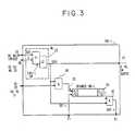
- FIG. 3represents a replaceable unit enabling the principle of the present invention to be implemented in the case where there is one chain per unit.
- FIG. 4represents a replaceable unit in the case where there are several chains per unit.
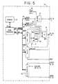
- Figure ' 5shows the part of the control circuit necessary for the operation of the device of the present invention.
- the control circuit 10which comprises means for controlling clocks and means for sending and receiving data in LSSD mode, in a conventional manner, comprises for each replaceable unit (in the example chosen. A card), a line d data input in LSSD SDI mode, a data output line in LSSD SDO mode and a control line for sending clock A: GATE A. It is assumed that in this machine, the clock signal B is applied continuously.
- Figure .2shows schematically the principle of the present invention.
- the datais sent and received as in previous machines by the control circuit 10 under the control of a microprocessor for example.
- chains SI to Sn of flip-flops SRLare formed in which the data to be loaded in the chains LSSD are introduced under control of the clock A (SH DL 21) .
- Figure 2there is shown schematically a single chain in each RU unit. However, as will be described with reference to FIG. 4, each unit can comprise several chains.
- the datais sent on a DL 20 data loop, from which the RU units receive the input data by the SDI lines and on which they place the output data by the SDO lines, under control of the clock signals A on the SH DL 21 data shift control line.
- each RU-i unitis placed an addressing circuit Mi 22 which comprises at least one flip-flop.
- Each flip-flop of the addressing circuitreceives offset clock pulses from the circuit 10 by the line SH ML 23.
- the flip-flops of all the addressing circuitsare linked together to form a shift register, by a control loop ML 24.
- the state of the flip-flops of the addressing circuits Mi 22depends of the information sent on the loop ML 24 by the circuit 10. According to the state of the flip-flops, the loading of the data in a selected chain is authorized. This is shown schematically in the figure by the line Ai 25 in each of the units.
- a means enabling the addressing information of each unit to be sent to the control loop ML 24will be described later with reference to FIG. 5.
- a RU-i unit comprising only one chainis shown in Figure 3.
- the chain of flip-flops formed in this unit for testing the logic of the unitis shown diagrammatically at 30.
- This chainconstitutes a shift register, each stage of which comprises two flip-flops L1, L2 arranged as shown in the diagram of the article. cited in reference.
- the test data in LSSD modeare applied in series to the input SDI-i at point 31, and under the control of a clock signal on the input A 32 of each flip-flop, they are shifted in the register.
- the output data to be analyzed to carry out the test or locate a faultis collected on the SDO-i terminal at point 33.
- the addressing flip-flop Mi in FIG. 2consists of a stage SRL-i 34 comprising two rockers L1, L2.
- An AND circuit 38has one of its inputs connected to the output SDO 37 of the addressing flip-flop 34 and another input receives from the line SH DL 21 at point 39 the clock signal A generated in the control circuit 10 when the system is in LSSD mode.
- An AND gate 40receives on one of its inputs the output of the flip-flop L2 of the last stage of the chain 30 and on its other input the output SDO 37 of the addressing flip-flop 34. Consequently when the unit RU-i has been addressed, the data to be analyzed is collected at the output SDO-i of the AND gate 40 at point 33 and returned to the control circuit 10 by the data loop DL 20.
- the RU-i unitis connected to the ML 24 control and DL 20 data loops in the same way as in the previous hypothesis described with reference to FIG. 3. Consequently the same reference numbers are used to reference the terminals input / output of the RU-i unit.
- the datais loaded and extracted from the strings in the same way as previously described.
- two AND circuits 38-j and 40-j arranged like the AND circuits 38 and 40 of FIG. 3are provided.
- the addressing circuit that causes the doors to openis different.
- the Mi addressing circuitincludes several SRL flip-flops.
- three flip-flops SRLare represented 42, 43, 44 which supply on their outputs 45, 46, 47 three address bits, which makes it possible to address 8 chains.
- the first flip-flophas its SDI input connected to the loop ML 24 at point 35.
- Each of the clock inputs A of the three flip-flops 42. 43 and 44receives an offset pulse taken at point 36 of the line SH ML 23 and supplied by the control circuit 10.
- the SDO output 37 of the flip-flop 44is connected to the SDI input of the first flip-flop 42 of the next unit by the loop ML 24.
- the output AND gates 40-1 to 40-pbeing opened by the address selection signal, on the line SDO-i at point 33, only the output data from the selected channel are found. These data are returned to the control circuit by the data loop DL 20 as described with reference to FIG. 2.
- the control circuitconsists of a microprocessor 50 with its memory 51 in which the control program and data are stored.
- the microprocessorcommunicates with the outside via external registers which are addressed under program control by the address bus 52, the data are transferred into the register addressed by the data bus 53.
- FIG. 5is shown diagrammatically 5 external registers 54, 55, 59, 60 and 65.
- the first 54partly consists of a single flip-flop which is set to 1 when the system is placed in LSSD mode.
- the second register 55includes another flip-flop which is set to 1 during the addressing phase.
- the output of the flip-flop of register 55is inverted by the inverter 56.
- An AND gate 57has an input connected to flip-flop 54, and another input receiving from clock 58 the clock signal A, used to control the flip-flops of the various channels and apply the clock signal A to the line SH DL 21 in LSSD mode when the addressing phase is complete.
- a register 59is loaded with information which indicates according to the selected RU unit the number of clock pulses to be sent on the line SH ML 23. For example to address the RU-i unit in the event that each circuit 22 has m flip-flops to address p channels in each unit, i ⁇ m clock pulses must be sent.
- a register 60is loaded with the address bits indicating the particular chain to be addressed in the selected unit. The content of this register is sent in series on the ML 24 control loop. under control of the clock pulses SH ML 23.
- the clock pulses on the line SH ML 23are generated from the content of the register 59 by a control circuit 61 which includes a clock 62, a comparison circuit 63 and an AND gate 64 open in LSSD and ADDRESSING mode. At each clock pulse applied to a DECRE input of register 59. the content of the register is decremented by 1.
- the content of the registeris equal to 0 everywhere, and the comparison circuit 63 which compares the content of the register with a configuration 0 everywhere provides a signal which closes the AND gate 64 so that no pulse appears on SH ML 23 output.
- the circuit 63opens the AND gate 64 which lets the clock pulses pass on the line SH ML 23.
- the content of the register 59is decremented by one and at the end of nine pulses the content of the register will be equal to zero everywhere and the clock pulses will no longer be sent on the line SH ML 23.
- the addressing phaseis then terminated and the flip-flop 55 is reset to zero, which causes the sending of the clock pulses A on the line SH DL 21.
- the data to be sent to the channel thus selectedare placed in register 65 to be sent in series on the DL 20 loop by the DEPART terminal.
- the data extracted from the chain selected after shift and collected at the terminal SDO at point 33are reapplied to register 65.
- the register 65is read, under program control, so that its content is transferred to the microprocessor for analysis.
- the chain of address latches of all unitsis restored by sending on the line SH ML 23 a number of pulses of nxm corresponding clock 'addressing the last unit and sending a bit pattern of 'address 0 0 0 ... in register 60.
- the addressing circuitcould be made up of as many flip-flops as there are chains in each unit, a flip-flop allowing the selection of a chain. At this time the configuration of address bits is not coded.
- the register 60must have p positions in order to send an address configuration with p bits to determine the state of the p flip-flops for addressing and the number of clock pulses necessary to propagate the configuration of bits desired will be larger, so the addressing operation will take longer.
- the procedure for addressing the various unitsalso has the advantage that it is possible to delete or add units without having to make any modifications to the circuits. You just have to change the number of clock pulses on the line SH ML 23.
Landscapes
- Engineering & Computer Science (AREA)
- General Engineering & Computer Science (AREA)
- Physics & Mathematics (AREA)
- General Physics & Mathematics (AREA)
- Test And Diagnosis Of Digital Computers (AREA)
- Tests Of Electronic Circuits (AREA)
Description
Translated fromFrenchLa présente invention concerne un dispositif pour le chargement et la lecture de données dans différentes chaînes de bascules d'un système de traitement de données en vue du test et de la localisation des pannes ou de l'initialisation du système. Elle concerne plus particulièrement un tel dispositif utilisable pour envoyer des données de test ou d'initialisation aux différentes chaînes de bascules d'un système réalisé en suivant les règles de la technique de conception avec analyse sensible au niveau (Level Sensitive Scan Design LSSD).The present invention relates to a device for loading and reading data in different flip-flop chains of a data processing system for the purpose of testing and locating faults or initializing the system. It relates more particularly to such a device which can be used to send test or initialization data to the various flip-flop chains of a system produced by following the rules of the design technique with level sensitive analysis (Level Sensitive Scan Design LSSD).
Ainsi qu'il est décrit dans l'article paru dans la revue « Electronics du 15 mars 1979 aux pages 108 à 110, l'intégration de plus en plus poussée des circuits logiques composant les machines a conduit à la nécessité de concevoir les circuits de façon que le test en soit possible aux différents stades de la réalisation : conception et fabrication et ultérieurement lorsque la machine est installée et qu'il faut localiser les pannes. La conception des circuits avec analyse sensible au niveau (LSSD : Level Sensitive Scan Design) décrite dans cet article permet de faciliter le test de même que l'initialisation des circuits. Dans les machines conçues suivant la technique LSSD, les circuits logiques sont intégrés dans des blocs assemblés sur des cartes elles- mêmes enfichées sur des panneaux. Ainsi qu'il est décrit dans l'article, le test des blocs nécessite l'envoi et la réception des données d'analyse d'entrée et de sortie SDI et SDO ainsi que l'envoi de signaux d'horloge à partir d'un circuit de commande centralisé.As described in the article published in the review "Electronics of March 15, 1979 on pages 108 to 110, the increasingly advanced integration of the logic circuits making up the machines has led to the need to design the circuits of so that the test is possible at the various stages of production: design and manufacture and later when the machine is installed and it is necessary to locate faults. The design of circuits with level sensitive analysis (LSSD: Level Sensitive Scan Design) described in this article makes it possible to facilitate the test as well as the initialization of the circuits. In machines designed according to the LSSD technique, the logic circuits are integrated in blocks assembled on cards themselves plugged into panels. As described in the article, block testing requires sending and receiving SDI and SDO input and output analysis data as well as sending clock signals from a centralized control circuit.
Des éléments d'emmagasinage SRL constitués de deux bascules L1 et L2 disposées comme décrit dans l'article, sont reliés en mode de test, qui sera appelé mode LSSD, pour former une chaîne de bascules constituant un registre à décalage.Storage elements SRL made up of two flip-flops L1 and L2 arranged as described in the article, are connected in test mode, which will be called LSSD mode, to form a chain of flip-flops constituting a shift register.
Suivant le degré de finesse que l'on désire atteindre, c'est-à-dire quel type de composant défectueux on désire pouvoir isoler, les chaînes sont formées des bascules d'un bloc, ou des chaînes de composants (cartes, panneaux) sont formées.Depending on the degree of finesse that one wishes to achieve, that is to say what type of defective component one wishes to be able to isolate, the chains are formed of rockers of a block, or chains of components (cards, panels) are formed.
Le composant que l'on désire pouvoir isoler sera appelé unité remplaçable RU.The component that you want to be able to isolate will be called a replaceable unit RU.
Dans les machines comprenant un grand nombre de circuits. le nombre de chaînes à créer pour le test est important et en conséquence le circuit de commande centralisé doit pouvoir envoyer les données de test à chaque chaîne. Ce qui nécessite pour chaque chaîne quatre bornes d'entrée/sortie et quatre lignes : SDI, SDO, horloge A et B. Le circuit de commande centralisé est réalisé sous forme d'un circuit intégré VLSI et actuellement le nombre des entréesisorties doit être réduit au minimum. En effet, ajouter quelques circuits n'ajoute que très peu au prix des machines mais avoir beaucoup d'entrées/sorties aux blocs de circuits intégrés et beaucoup de câbles pour transporter les signaux est très coûteux.In machines with a large number of circuits. the number of chains to be created for the test is large and therefore the centralized control circuit must be able to send the test data to each chain. Which requires for each chain four input / output terminals and four lines: SDI, SDO, clock A and B. The centralized control circuit is made in the form of an integrated VLSI circuit and currently the number of outputs is to be reduced at least. Indeed, adding a few circuits adds very little to the price of the machines but having a lot of I / O to the blocks of integrated circuits and a lot of cables to transport the signals is very expensive.
L'article paru dans IEEE en 1979. Test Confe- rence, Digest of Papers 23 au 25 Octobre 1979. aux pages 29 à 36 et le brevet US 4 268 902 décrivent un interface de maintenance, comportant un circuit logique de commande utilisable pour contrôler le chargement et la lecture de chaînes de registres à décalage. Un inconvénient d'un tel circuit est que l'adressage de chaînes ne permet pas de réduire au minimum le nombre de bornes d'entrée/sortie du circuit logique de commande.The article published in IEEE in 1979. Test Conference, Digest of Papers October 23 to 25, 1979. on pages 29 to 36 and US Patent 4,268,902 describe a maintenance interface, comprising a logic control circuit usable for controlling loading and reading shift register strings. A drawback of such a circuit is that the addressing of strings does not make it possible to minimize the number of input / output terminals of the logic control circuit.
Le brevet DE-A 1 927 549 décrit une structure de bus en anneau pour transporter les données et les adresses entre une unité centrale et des unités d'entrée/sortie. Dans cette structure les unités d'entrée/sortie sont connectées au bus d'adresse en parallèle, de façon classique de telle sorte que dans chaque unité d'entrée/sortie un circuit permet de décoder la configuration d'adresse sur le bus d'adresse.Patent DE-A 1 927 549 describes a ring bus structure for transporting data and addresses between a central unit and input / output units. In this structure, the input / output units are connected to the address bus in parallel, in a conventional manner so that in each input / output unit, a circuit makes it possible to decode the address configuration on the bus. address.
Le brevet US-A 3 964 088 décrit un système de traitement de l'information incorporant diverses unités dans chacune desquelles est créé au moins un registre à décalage. L'adressage d'un registre se fait à l'aide d'au moins une bascule qui est contrôlée par un circuit général comportant un décodeur d'adresse.US-A 3,964,088 describes an information processing system incorporating various units in each of which at least one shift register is created. The addressing of a register is done using at least one flip-flop which is controlled by a general circuit comprising an address decoder.
Les différentes bascules d'adressage dans les différentes unités sont contrôlées par le circuit général de l'unité, ce qui nécessite un grand nombre de bornes d'entrée/sortie.The different addressing flip-flops in the different units are controlled by the general circuit of the unit, which requires a large number of input / output terminals.
En conséquence, un objet de la présente invention est de réaliser un dispositif permettant de charger et de lire des chaînes de bascules dans un système tel qu'une unité de traitement centrale pour les opérations de tests, de diagnostics ou d'initialisation, à partir d'un circuit de commande centralisé qui comporte un nombre minimum de bornes d'entrée/sortie.Consequently, an object of the present invention is to provide a device making it possible to load and read scales of scales in a system such as a central processing unit for the operations of tests, diagnostics or initialization, from a centralized control circuit which has a minimum number of input / output terminals.
La présente invention concerne un dispositif de chargement et de lecture de chaînes de bascules à décalage utilisable pour le test, le dépannage et l'initialisation d'un système de traitement de données dont les composants sont disposés sur n unités remplaçables qui comportent chacun p chaînes de bascules. Il comprend un circuit de commande connecté à une boucle de contrôle et à une boucle de données.The present invention relates to a device for loading and reading chains of shift scales to be used for testing, troubleshooting and initializing a data processing system, the components of which are arranged on n replaceable units each comprising p chains. flip-flops. It includes a control circuit connected to a control loop and to a data loop.
Le circuit de commande génère une configuration de bits d'adresse et traite les données à envoyer dans la chaîne sélectionnée et les données reçues de la chaîne sélectionnée.The control circuit generates an address bit pattern and processes the data to be sent in the selected chain and the data received from the selected chain.
La boucle de contrôle est connectée au circuit de commande et reçoit de ce dispositif de commande une configuration de bits d'adresse qui sont envoyés en série sur la boucle.The control loop is connected to the control circuit and receives from this control device a configuration of address bits which are sent serially on the loop.
Dans chaque unité remplaçable est disposé un circuit d'adressage sensible à la configuration des bits d'adresse sur la boucle de contrôle, ledit circuit ayant p sorties et fournissant sur une des p sorties, qui est déterminée par la configuration des bits d'adresse, un signal de sélection de chaîne. Ledit circuit d'adressage comporte au moins une bascule d'adressage, et les différentes bascules d'adressage dans les différentes unités remplaçables, sont connectées de façon à constituer un registre à décalage.In each replaceable unit there is an addressing circuit sensitive to the configuration of the address bits on the control loop, said circuit having p outputs and providing on one of the p outputs, which is determined by the configuration of the address bits , a channel selection signal. Said addressing circuit comprises at least one addressing flip-flop, and the different addressing flip-flops in the different replaceable units, are connected so as to constitute a shift register.
Le circuit de commande comprend des premiers moyens de génération d'impulsion d'horloge qui envoient sur une première ligne de sortie dudit circuit de commande des premières impulsions d'horloge dont le nombre est fonction de l'unité dans laquelle se trouve la chaîne à sélectionner, ces impulsions étant appliquées en parallèle aux bascules d'adressage pour provoquer le décalage de la configuration des bits d'adresse dans le registre formé par les bascules d'adressage.The control circuit comprises first clock pulse generation means which send on a first output line of said control circuit first clock pulses, the number of which depends on the unit in which the chain is located. select, these pulses being applied in parallel to the addressing flip-flops to cause the shift of the configuration of the address bits in the register formed by the addressing flip-flops.
Toutes les unités remplaçables sont connectées à la boucle de données et par cette boucle, reçoivent du circuit de commande les données à charger dans la chaîne sélectionnée et envoient les données lues de ladite chaîne.All the replaceable units are connected to the data loop and by this loop, receive from the control circuit the data to be loaded in the selected chain and send the data read from said chain.
Une première série de p portes d'entrée est placée dans chaque unité remplaçable, chacune desdites portes étant connectée à une des p sorties du circuit d'adressage pour être ouverte par le signal de sélection de chaîne afin d'autoriser le chargement des données provenant de la boucle de données dans la chaîne sélectionnée.A first series of p input doors is placed in each replaceable unit, each of said doors being connected to one of the p outputs of the addressing circuit to be opened by the channel selection signal in order to allow the loading of the data coming from of the data loop in the selected string.
Dans un mode de réalisation préférée, les circuits d'adressage comportent chacun m bascules d'adressage avec p = 2m, les m bascules de tous les circuits étant connectées pour former un registre à décalage, et un sélecteur de chaîne ayant p sorties sensible à l'état des bascules d'adressage pour fournir sur une des p sorties le signal de sélection d'adresse.In a preferred embodiment, the addressing circuits each comprise m addressing flip-flops with p = 2m, the m flip-flops of all the circuits being connected to form a shift register, and a chain selector having p outputs sensitive to the state of the addressing flip-flops to supply the address selection signal on one of the p outputs.
Le circuit de commande comprend des seconds moyens de génération d'impulsions d'horloge pour générer sur une seconde ligne de sortie du circuit de commande des secondes impulsions d'horloge lorsque la chaîne à sélectionner a été adressée. Les secondes impulsions sont appliquées à chacune des p portes d'entrée de toutes les unités remplaçables, afin que la porte ouverte par le circuit d'adressage provoque leur application à la chaîne sélectionnée pour y charger les données qui circulent sur la boucle de données.The control circuit comprises second clock pulse generation means for generating on a second output line of the control circuit second clock pulses when the chain to be selected has been addressed. The second pulses are applied to each of the p input doors of all the replaceable units, so that the door opened by the addressing circuit causes their application to the selected chain to load the data flowing there on the data loop.
Chaque unité remplaçable comporte une seconde série de p portes de sortie chacune desdites portes étant ouverte par une des sorties du circuit d'adressage afin de faire passer le contenu de la chaîne sélectionnée sur la boucle de données.Each replaceable unit comprises a second series of p output doors, each of said doors being opened by one of the outputs of the addressing circuit in order to pass the content of the selected chain over the data loop.
La figure 1 représente un arrangement d'un système de l'art antérieur.Figure 1 shows an arrangement of a system of the prior art.
La figure 2 représente schématiquement le dispositif de la présente invention.FIG. 2 schematically represents the device of the present invention.
La figure 3 représente une unité remplaçable permettant de mettre en oeuvre le principe de la présente invention dans le cas où il y a une chaîne par unité.FIG. 3 represents a replaceable unit enabling the principle of the present invention to be implemented in the case where there is one chain per unit.
La figure 4 représente une unité remplaçable dans le cas où il y a plusieurs chaînes par unité.FIG. 4 represents a replaceable unit in the case where there are several chains per unit.
La figure'5 représente la partie du circuit de commande nécessaire au fonctionnement du dispositif de la présente invention.Figure' 5 shows the part of the control circuit necessary for the operation of the device of the present invention.
Dans le brevet US A 4 268 902 est décrit un interface de maintenance qui permet de tester un certain nombre d'éléments d'une unité de traitement central. Pour cela quatre chaînes de registres à décalage peuvent être constituées et le circuit logique de commande comporte quatre séries de lignes SDI, SDO. Du fait du nombre restreint des chaînes, le nombre des entrées/sorties n'est pas encore très élevé mais dans les machines de taille importante comportant un grand nombre de blocs disposés sur des cartes le nombre des entrées/sorties du circuit de commande peut devenir très élevé, comme représenté schématiquement sur la figure 1.In US
Le circuit de commande 10, qui comprend des moyens pour contrôler des horloges et des moyens pour envoyer et recevoir les données en mode LSSD, de façon classique, comporte pour chaque unité remplaçable (dans l'exemple choisi. une carte), une ligne d'entrée de données en mode LSSD SDI, une ligne de sortie de données en mode LSSD SDO et une ligne de contrôle d'envoi de l'horloge A : GATE A. Il est supposé que dans cette machine, le signal de l'horloge B est appliqué en permanence.The
La figure .2 représente schématiquement le principe de la présente invention.Figure .2 shows schematically the principle of the present invention.
Les données sont envoyées et reçues comme dans les machines antérieures par le circuit de commande 10 sous contrôle d'un microprocesseur par exemple. Dans les unités à tester ou à initialiser RUI à RUn, en mode LSSD, des chaînes SI à Sn de bascules SRL sont constituées dans lesquelles les données à charger dans les chaînes LSSD sont introduites sous contrôle de l'horloge A (SH DL 21). Sur la figure 2 on a représenté schématiquement une seule chaîne dans chaque unité RU. Cependant comme cela sera décrit en référence à la figure 4, chaque unité peut comporter plusieurs chaînes.The data is sent and received as in previous machines by the
Les données sont envoyées sur une boucle de données DL 20, de laquelle les unités RU reçoivent les données d'entrée par les lignes SDI et sur laquelle elles placent les données de sortie par les lignes SDO, sous contrôle des signaux d'horloge A sur la ligne de contrôle de décalage des données SH DL 21.The data is sent on a
Dans chaque unité RU-i est placé un circuit d'adressage Mi 22 qui comporte au moins une bascule. Chaque bascule du circuit d'adressage reçoit des impulsions d'horloge de décalage du circuit 10 par la ligne SH ML 23. Les bascules de tous les circuits d'adressage sont reliées entre elles pour former un registre à décalage, par une boucle de contrôle ML 24. L'état des bascules des circuits d'adressage Mi 22 dépend de l'information envoyée sur la boucle ML 24 par le circuit 10. Suivant l'état des bascules, le chargement des données dans une chaîne sélectionnée est autorisé. Ceci est représenté schématiquement sur la figure par la ligne Ai 25 dans chacune des unités. Un moyen permettant d'envoyer l'information d'adressage de chaque unité sur la boucle de contrôle ML 24 sera décrit ultérieurement en référence à la figure 5.In each RU-i unit is placed an addressing
Grâce à cet arrangement, pour tester n unités il ne faut que 6 entrées/sorties pour le circuit 1 au lieu de 3 x n dans les systèmes de l'art antérieur tel que représenté dans la figure 1.'Thanks to this arrangement, to test n units, only 6 inputs / outputs are required for
Une unité RU-i ne comportant qu'une chaîne est représentée sur la figure 3.A RU-i unit comprising only one chain is shown in Figure 3.
Sur la figure 2, les numéros de référence 31, 33, 35. 36, 37 et 39 ont été indiqués pour montrer comment est connectée l'unité RU-i dans l'ensemble de la figure 2.In Figure 2,
La chaîne des bascules formée dans cette unité pour le test de la logique de l'unité est représentée schématiquement en 30. Cette chaîne constitue un registre à décalage dont chaque étage comporte deux bascules L1, L2 disposées comme représenté sur le schéma de l'article cité en référence. Les données de test en mode LSSD sont appliquées en série à l'entrée SDI-i au point 31, et sous contrôle d'un signal d'horloge sur l'entrée A 32 de chaque bascule, elles sont décalées dans le registre. Les données de sortie à analyser pour réaliser le test ou localiser une panne sont recueillies sur la borne SDO-i au point 33.The chain of flip-flops formed in this unit for testing the logic of the unit is shown diagrammatically at 30. This chain constitutes a shift register, each stage of which comprises two flip-flops L1, L2 arranged as shown in the diagram of the article. cited in reference. The test data in LSSD mode are applied in series to the input SDI-i at
La bascule d'adressage Mi de la figure 2 est constituée d'un étage SRL-i 34 comprenant deux basculES L1, L2.The addressing flip-flop Mi in FIG. 2 consists of a stage SRL-
Sur l'entrée SDI de la bascule L1 est appliquée l'information d'adresse qui circule sur la boucle de contrôle ML 24, prise au point 35 (figure 2). L'entrée A de la bascule L1, au point 36, reçoit un signal d'horloge pour mettre à 1 la bascule 34 lorsque l'unité RU-i est adressée ou pour propager cette information aux étages SRL suivants en vue de l'adressage d'une unité sélectionnée par le circuit de commande 10. La sortie SDO de la bascule L2 au point 37 est connectée à l'entrée SDI de la bascule L1 de l'unité suivante pour former la boucle de contrôle ML 24.On the SDI input of the flip-flop L1 is applied the address information which circulates on the
Un circuit ET 38 a une de ses entrées connectée à la sortie SDO 37 de la bascule d'adressage 34 et une autre entrée reçoit de la ligne SH DL 21 au point 39 le signal d'horloge A généré dans le circuit de commande 10 lorsque le système est en mode LSSD.An AND
En conséquence si le circuit de commande 10 a provoqué l'adressage de l'unité RU-i en mettant à 1 la bascule SRL-i 34, le signal d'horloge A qui est envoyé par le circuit de commande 10 sur la ligne SH DL 21 est appliqué à la chaîne RU-i 30, par le circuit ET 38 alors ouvert. Les données sur la boucle de données DL 20 prises au point 31 sont donc chargées dans la chaîne 30 par l'entrée SDI-i.Consequently, if the
Une porte ET 40 reçoit sur une de ses entrées la sortie de la bascule L2 du dernier étage de la chaîne 30 et sur son autre entrée la sortie SDO 37 de la bascule d'adressage 34. En conséquence lorsque l'unité RU-i a été adressée, les données à analyser sont recueillies à la sortie SDO-i de la porte ET 40 au point 33 et renvoyées au circuit de commande 10 par la boucle de données DL 20.An AND
On va maintenant décrire en référence à la figure 4, l'application du principe décrit en référence aux figures 2 et 3 au test de plusieurs chaînes distinctes à l'intérieur de chaque unité RU-i.We will now describe with reference to FIG. 4, the application of the principle described with reference to FIGS. 2 and 3 to the testing of several distinct chains inside each RU-i unit.
On suppose que dans chaque unité RU-i on désire pouvoir accéder à plusieurs chaînes de bascules 41-1 à 41 p. Sur la figure 4, seules 4 chaînes ont été représentées. Dans un cas particulier, on supposera p égal à 8.We suppose that in each RU-i unit we want to be able to access several scales of scales 41-1 to 41 p. In Figure 4, only 4 chains have been shown. In a particular case, we will assume p equal to 8.
L'unité RU-i est connectée aux boucles de contrôle ML 24 et de données DL 20 de la même façon que dans l'hypothèse précédente décrite en référence à la figure 3. En conséquence les mêmes numéros de références sont utilisés pour référencer les bornes d'entrée/sortie de l'unité RU-i.The RU-i unit is connected to the
Les données sont chargées et extraites des chaînes de la même façon que précédemment décrit. Pour chaque chaîne, deux circuits ET 38-j et 40-j disposés comme les circuits ET 38 et 40 de la figure 3, sont prévus.The data is loaded and extracted from the strings in the same way as previously described. For each chain, two AND circuits 38-j and 40-j arranged like the AND
Le circuit d'adressage qui provoque l'ouverture des portes est différent.The addressing circuit that causes the doors to open is different.
Le circuit d'adressage Mi comporte plusieurs bascules SRL. Sur la figure 4 trois bascules SRL sont représentées 42, 43, 44 qui fournissent sur leurs sorties 45, 46, 47 trois bits d'adresse, ce qui permet d'adresser 8 chaînes. Le nombre m de bascules dépend du nombre p de chaînes à adresser et est tel que p = 2m.The Mi addressing circuit includes several SRL flip-flops. In FIG. 4, three flip-flops SRL are represented 42, 43, 44 which supply on their
La première bascule a son entrée SDI connectée à la boucle ML 24 au point 35. Chacune des entrées d'horloge A des trois bascules 42. 43 et 44 reçoit une impulsion de décalage prise au point 36 de la ligne SH ML 23 et fournie par le circuit de commande 10.The first flip-flop has its SDI input connected to the
La sortie SDO 37 de la bascule 44 est reliée à l'entrée SDI de la première bascule 42 de l'unité suivante par la boucle ML 24.The
Les trois bits d'adresse sont appliqués à un circuit sélecteur de chaînes 48 constitué d'un ensemble de portes et d'inverseurs qui fournit sur une de ses sorties 49-1 à 49-8, un signal de sélection de chaîne, en fonction de la configuration des bits d'adresse sur les sorties 45. 46. 47. Par exemple, lorsque la configuration des bits d'adresse est 000, seul le signal sur la sortie 49-1 est à 1 pour ouvrir la porte 38-1 et lorsque la configuration des bits d'adresse est 111, seul le signal sur la ligne 49-8 est à 1 pour ouvrir la porte 38-p (dans le cas où p = 8).The three address bits are applied to a
Une fois une chaîne sélectionnée, les données y sont introduites comme dans le cas de la disposition de la figure 3.Once a channel has been selected, the data is entered there as in the case of the arrangement of figure 3.
Les portes ET de sortie 40-1 à 40-p étant ouvertes par le signal de sélection d'adresse on ne retrouve sur la ligne SDO-i au point 33, que les données de sortie provenant de la chaîne sélectionnée. Ces données sont renvoyées au circuit de commande par la boucle de données DL 20 comme décrit en référence à la fig. 2.The output AND gates 40-1 to 40-p being opened by the address selection signal, on the line SDO-i at
On va maintenant décrire en référence à la figure 5, la partie du circuit de commande 10 utilisée pour envoyer l'information d'adresse sur la boucle de contrôle ML 24, dans l'hypothèse où plusieurs chaînes doivent être adressées dans chaque unité.We will now describe with reference to FIG. 5, the part of the
Dans un mode de réalisation préféré le circuit de commande est constitué d'un microprocesseur 50 avec sa mémoire 51 dans laquelle sont stockés le programme de commande ainsi que des données. Le microprocesseur communique avec l'extérieur par des registres externes qui sont adressés sous contrôle du programme par le bus d'adresse 52, les données sont transférées dans le registre adressé par le bus de données 53. Sur la figure 5 on a représenté schématiquement 5 registres externes 54, 55, 59, 60 et 65. Le premier 54 est en partie constitué d'une seule bascule qui est mise à 1 lorsque le système est placé en mode LSSD. Le second registre 55 comporte une autre bascule qui est mise à 1 pendant la phase d'adressage. La sortie de la bascule du registre 55 est inversée par l'inverseur 56. Une porte ET 57 a une entrée connectée à la bascule 54, et une autre entrée recevant de l'horloge 58 le signal d'horloge A, utilisé pour contrôler les bascules des différentes chaînes et appliquer le signal d'horloge A à la ligne SH DL 21 en mode LSSD lorsque la phase d'adressage est terminée.In a preferred embodiment, the control circuit consists of a
Un registre 59 est chargé avec une information qui indique suivant l'unité RU sélectionnée le nombre d'impulsions d'horloge à envoyer sur la ligne SH ML 23. Par exempte pour adresser l'unité RU-i dans l'hypothèse où chaque circuit d'adressage 22 comporte m bascules pour adresser p chaînes dans chaque unité, il faut envoyer i × m impulsions d'horloge.A
Un registre 60 est chargé avec les bits d'adresse indiquant la chaîne particulière à adresser dans l'unité sélectionnée. Le contenu de ce registre est envoyé en série sur la boucle de contrôle ML 24 . sous contrôle des impulsions d'horloge SH ML 23.A
Des zéros sont introduits dans le registre après chaque décalage par l'entrée FORCER 0 de façon qu'après m impulsions d'horloge (avec m = 3 dans l'exemple choisi), le contenu du registre 60 soit à 0 et que des 0 soient envoyés en ligne.Zeros are introduced into the register after each shift by the
Les impulsions d'horloge sur la ligne SH ML 23 sont générées à partir du contenu du registre 59 par un circuit de contrôle 61 qui comprend une horloge 62, un circuit de comparaison 63 et une porte ET 64 ouverte en mode LSSD et ADRESSAGE. A chaque impulsion d'horloge appliquée à une entrée DECRE du registre 59. le contenu du registre est décrémenté de 1.The clock pulses on the
Au départ, le contenu du registre est égal à 0 partout, et le circuit de comparaison 63 qui compare le contenu du registre avec une configuration 0 partout fournit un signal qui ferme la porte ET 64 de telle façon qu'aucune impulsion n'apparaît sur la sortie SH ML 23.At the start, the content of the register is equal to 0 everywhere, and the
Lorsque le registre est chargé à la valeur désirée pour adresser une unité, par exemple à 9 (0/0/1/0/0/1) pour adresser la troisième unité dans le cas où chaque unité comporte trois bascules d'adressage comme représenté sur la figure 4, le circuit 63 ouvre la porte ET 64 qui laisse passer les impulsions d'horloge sur la ligne SH ML 23. A chaque impulsion le contenu du registre 59 est décrémenté d'une unité et au bout de neuf impulsions le contenu du registre sera égal à zéro partout et les impulsions d'horloge ne seront plus envoyées sur la ligne SH ML 23.When the register is loaded at the desired value to address a unit, for example to 9 (0/0/1/0/0/1) to address the third unit in the case where each unit has three addressing flip-flops as shown in FIG. 4, the
Ces impulsions transfèrent le contenu du registre 60 sur la ligne ML 24, et la configuration de bits d'adresse de la chaîne sélectionnée dans l'unité est décalée bit après bit sur la ligne ML 24.These pulses transfer the content of
Les trois dernières impulsions d'horloge sur la ligne SH ML 23 provoquent l'introduction de la configuration de bits dans les trois bascules d'adressage (42 à 44) de l'unité sélectionnée.The last three clock pulses on the
La phase d'adressage est alors terminée et la bascule 55 est remise à zéro, ce qui provoque l'envoi des impulsions d'horloge A sur la ligne SH DL 21.The addressing phase is then terminated and the flip-
Les données à envoyer à la chaîne ainsi sélectionnée sont placées dans le registre 65 pour être envoyée en série sur la boucle DL 20 par la borne DEPART. Les données extraites de la chaîne sélectée après décalage et recueillies à la borne SDO au point 33 sont réappliquées au registre 65.The data to be sent to the channel thus selected are placed in
Lorsque toutes les données de test ont été envoyées, le registre 65 est lu, sous contrôle du programme pour que son contenu soit transféré au microprocesseur afin d'être analysé.When all the test data has been sent, the
La chaîne des bascules d'adressage de toutes les unités est restaurée en envoyant sur la ligne SH ML 23 un nombre d'impulsions d'horloge n x m ce qui correspond à' l'adressage de la dernière unité et en envoyant une configuration de bits d'adresse 0 0 0 ... dans le registre 60.The chain of address latches of all units is restored by sending on the line SH ML 23 a number of pulses of nxm corresponding clock'addressing the last unit and sending a bit pattern of '
Lorsque l'on fait une opération de chargement et de lecture d'une chaîne isolée, cette chaîne est .adressée et l'opération est réalisée comme précédemment décrit, ensuite les bascules d'adressage peuvent être restaurées en envoyant le nombre de zéro nécessaire sur la boucle de contrôle.When an operation of loading and reading an isolated chain is carried out, this chain is addressed and the operation is carried out as previously described, then the addressing flip-flops can be restored by sending the necessary number of zero to the control loop.
Lorsque l'on fait une opération de chargement et de lecture de l'ensemble des chaînes, on peut adresser par exemple les chaînes de même rang de toutes les unités en chargeant le numéro de chaîne désiré, par exemple 100 (chaîne 2), à chaque opération d'adressage sans forcer de zéro dans le registre 60 et en envoyant sur la ligne SH ML 23 pour chaque opération dé charge- ment/lecture trois impulsions d'horloge ; de cette façon, l'information d'adresse sera propagée dans la boucle de commande. On peut ainsi réaliser l'accès séquentiel à toutes les chaînes sans effectuer de restauration.When you load and read all the channels, you can, for example, send the same rank channels to all the units by loading the desired channel number, for example 100 (channel 2), to each addressing operation without forcing zero in
Bien entendu, le circuit d'adressage pourrait être constitué par autant de bascules qu'il y a de chaînes dans chaque unité, une bascule permettant la sélection d'une chaîne. A ce moment la configuration de bits d'adresse n'est pas codée. Bien entendu dans cette hypothèse, le registre 60 doit avoir p positions afin d'envoyer une configuration d'adresse à p bits pour déterminer l'état des p bascules d'adressage et le nombre des impulsions d'horloge nécessaires pour propager la configuration de bits désitée sera plus grand, si bien que l'opération d'adressage prendra plus de temps.Of course, the addressing circuit could be made up of as many flip-flops as there are chains in each unit, a flip-flop allowing the selection of a chain. At this time the configuration of address bits is not coded. Of course in this hypothesis, the
La procédure d'adressage des différentes unités présente en outre l'avantage que l'on peut supprimer ou ajouter des unités sans avoir à apporter des modifications dans les circuits. Il suffit simplement de changer le nombre des impulsions d'horloge sur la ligne SH ML 23.The procedure for addressing the various units also has the advantage that it is possible to delete or add units without having to make any modifications to the circuits. You just have to change the number of clock pulses on the
Claims (6)
Priority Applications (4)
| Application Number | Priority Date | Filing Date | Title |
|---|---|---|---|
| EP82430028AEP0104293B1 (en) | 1982-09-28 | 1982-09-28 | Device for loading and reading different chains of bistable circuits in a data processing system |
| DE8282430028TDE3274910D1 (en) | 1982-09-28 | 1982-09-28 | Device for loading and reading different chains of bistable circuits in a data processing system |
| JP58171420AJPS5975346A (en) | 1982-09-28 | 1983-09-19 | System of coding into latch train and reading out thereof |
| US06/533,188US4597042A (en) | 1982-09-28 | 1983-09-19 | Device for loading and reading strings of latches in a data processing system |
Applications Claiming Priority (1)
| Application Number | Priority Date | Filing Date | Title |
|---|---|---|---|
| EP82430028AEP0104293B1 (en) | 1982-09-28 | 1982-09-28 | Device for loading and reading different chains of bistable circuits in a data processing system |
Publications (2)
| Publication Number | Publication Date |
|---|---|
| EP0104293A1 EP0104293A1 (en) | 1984-04-04 |
| EP0104293B1true EP0104293B1 (en) | 1986-12-30 |
Family
ID=8189984
Family Applications (1)
| Application Number | Title | Priority Date | Filing Date |
|---|---|---|---|
| EP82430028AExpiredEP0104293B1 (en) | 1982-09-28 | 1982-09-28 | Device for loading and reading different chains of bistable circuits in a data processing system |
Country Status (4)
| Country | Link |
|---|---|
| US (1) | US4597042A (en) |
| EP (1) | EP0104293B1 (en) |
| JP (1) | JPS5975346A (en) |
| DE (1) | DE3274910D1 (en) |
Families Citing this family (45)
| Publication number | Priority date | Publication date | Assignee | Title |
|---|---|---|---|---|
| DE3373730D1 (en)* | 1983-12-15 | 1987-10-22 | Ibm | Series-parallel/parallel-series device for variable bit length configuration |
| JPH0772744B2 (en)* | 1984-09-04 | 1995-08-02 | 株式会社日立製作所 | Semiconductor integrated circuit device |
| JPH0668732B2 (en)* | 1984-11-21 | 1994-08-31 | 株式会社日立製作所 | Sukiyan method for information processing equipment |
| GB8518860D0 (en)* | 1985-07-25 | 1985-08-29 | Int Computers Ltd | Digital integrated circuits |
| NL8502476A (en)* | 1985-09-11 | 1987-04-01 | Philips Nv | METHOD FOR TESTING CARRIERS WITH MULTIPLE DIGITAL-ACTING INTEGRATED CIRCUITS, CARRYING WITH SUCH CIRCUITS, INTEGRATED CIRCUIT SUITABLE FOR APPLICATION TO SUCH CARRIER, AND TESTING DEVICE FOR TESTING SUCH. |
| ATE84165T1 (en)* | 1985-10-15 | 1993-01-15 | Sony Corp | LOGICAL CIRCUIT WITH LINKED MULTIPORT FLIP FLOPS. |
| US4701921A (en)* | 1985-10-23 | 1987-10-20 | Texas Instruments Incorporated | Modularized scan path for serially tested logic circuit |
| US4710931A (en)* | 1985-10-23 | 1987-12-01 | Texas Instruments Incorporated | Partitioned scan-testing system |
| US5032783A (en)* | 1985-10-23 | 1991-07-16 | Texas Instruments Incorporated | Test circuit and scan tested logic device with isolated data lines during testing |
| JPH0690260B2 (en)* | 1986-05-30 | 1994-11-14 | 三菱電機株式会社 | Logic circuit test equipment |
| JPH0691140B2 (en)* | 1986-07-11 | 1994-11-14 | 日本電気株式会社 | Semiconductor integrated circuit |
| US4710927A (en)* | 1986-07-24 | 1987-12-01 | Integrated Device Technology, Inc. | Diagnostic circuit |
| US4872169A (en)* | 1987-03-06 | 1989-10-03 | Texas Instruments Incorporated | Hierarchical scan selection |
| US4876501A (en)* | 1987-04-13 | 1989-10-24 | Prime Computer, Inc. | Method and apparatus for high accuracy measurment of VLSI components |
| JPS63256877A (en)* | 1987-04-14 | 1988-10-24 | Mitsubishi Electric Corp | test circuit |
| US4860290A (en)* | 1987-06-02 | 1989-08-22 | Texas Instruments Incorporated | Logic circuit having individually testable logic modules |
| US5535331A (en)* | 1987-09-04 | 1996-07-09 | Texas Instruments Incorporated | Processor condition sensing circuits, systems and methods |
| JPH01132980A (en)* | 1987-11-17 | 1989-05-25 | Mitsubishi Electric Corp | Electronic circuit with test function |
| JPH01132979A (en)* | 1987-11-17 | 1989-05-25 | Mitsubishi Electric Corp | Electronic circuit with test function |
| DE68928837T2 (en)* | 1988-09-07 | 1999-05-12 | Texas Instruments Inc., Dallas, Tex. | Check buffer / register |
| EP0628831B1 (en)* | 1988-09-07 | 1998-03-18 | Texas Instruments Incorporated | Bidirectional boundary scan test cell |
| US6304987B1 (en) | 1995-06-07 | 2001-10-16 | Texas Instruments Incorporated | Integrated test circuit |
| US5483518A (en) | 1992-06-17 | 1996-01-09 | Texas Instruments Incorporated | Addressable shadow port and protocol for serial bus networks |
| JP3005250B2 (en)* | 1989-06-30 | 2000-01-31 | テキサス インスツルメンツ インコーポレイテツド | Bus monitor integrated circuit |
| US5805792A (en)* | 1989-07-31 | 1998-09-08 | Texas Instruments Incorporated | Emulation devices, systems, and methods |
| JP2632731B2 (en)* | 1989-08-02 | 1997-07-23 | 三菱電機株式会社 | Integrated circuit device |
| US5079725A (en)* | 1989-11-17 | 1992-01-07 | Ibm Corporation | Chip identification method for use with scan design systems and scan testing techniques |
| US5274648A (en)* | 1990-01-24 | 1993-12-28 | International Business Machines Corporation | Memory card resident diagnostic testing |
| US6675333B1 (en) | 1990-03-30 | 2004-01-06 | Texas Instruments Incorporated | Integrated circuit with serial I/O controller |
| US5581564A (en)* | 1990-12-18 | 1996-12-03 | Integrated Device Technology, Inc. | Diagnostic circuit |
| US5271019A (en)* | 1991-03-15 | 1993-12-14 | Amdahl Corporation | Scannable system with addressable scan reset groups |
| US5701309A (en)* | 1992-12-02 | 1997-12-23 | At&T Global Information Solutions Company | Automated test equipment digital tester expansion apparatus |
| US5463338A (en)* | 1993-06-07 | 1995-10-31 | Vlsi Technology, Inc. | Dual latch clocked LSSD and method |
| US5530706A (en)* | 1993-10-15 | 1996-06-25 | Hewlett-Packard Company | Non-destructive sampling of internal states while operating at normal frequency |
| US5448525A (en)* | 1994-03-10 | 1995-09-05 | Intel Corporation | Apparatus for configuring a subset of an integrated circuit having boundary scan circuitry connected in series and a method thereof |
| US5821773A (en)* | 1995-09-06 | 1998-10-13 | Altera Corporation | Look-up table based logic element with complete permutability of the inputs to the secondary signals |
| US5969538A (en) | 1996-10-31 | 1999-10-19 | Texas Instruments Incorporated | Semiconductor wafer with interconnect between dies for testing and a process of testing |
| US5869979A (en) | 1996-04-05 | 1999-02-09 | Altera Corporation | Technique for preconditioning I/Os during reconfiguration |
| US6028983A (en)* | 1996-09-19 | 2000-02-22 | International Business Machines Corporation | Apparatus and methods for testing a microprocessor chip using dedicated scan strings |
| US6408413B1 (en) | 1998-02-18 | 2002-06-18 | Texas Instruments Incorporated | Hierarchical access of test access ports in embedded core integrated circuits |
| US6405335B1 (en) | 1998-02-25 | 2002-06-11 | Texas Instruments Incorporated | Position independent testing of circuits |
| US6184707B1 (en) | 1998-10-07 | 2001-02-06 | Altera Corporation | Look-up table based logic element with complete permutability of the inputs to the secondary signals |
| US7058862B2 (en) | 2000-05-26 | 2006-06-06 | Texas Instruments Incorporated | Selecting different 1149.1 TAP domains from update-IR state |
| US6728915B2 (en) | 2000-01-10 | 2004-04-27 | Texas Instruments Incorporated | IC with shared scan cells selectively connected in scan path |
| US6769080B2 (en) | 2000-03-09 | 2004-07-27 | Texas Instruments Incorporated | Scan circuit low power adapter with counter |
Citations (1)
| Publication number | Priority date | Publication date | Assignee | Title |
|---|---|---|---|---|
| DE1927549A1 (en)* | 1969-05-30 | 1970-12-03 | Ibm Deutschland | Error checking device in electronic data processing systems |
Family Cites Families (10)
| Publication number | Priority date | Publication date | Assignee | Title |
|---|---|---|---|---|
| FR2256706A5 (en)* | 1973-12-27 | 1975-07-25 | Cii | |
| US4030072A (en)* | 1974-12-18 | 1977-06-14 | Xerox Corporation | Computer system operation and control |
| US4041471A (en)* | 1975-04-14 | 1977-08-09 | Scientific Micro Systems, Inc. | Data processing system including a plurality of programmed machines and particularly including a supervisor machine and an object machine |
| US4023142A (en)* | 1975-04-14 | 1977-05-10 | International Business Machines Corporation | Common diagnostic bus for computer systems to enable testing concurrently with normal system operation |
| JPS5833576B2 (en)* | 1977-03-14 | 1983-07-20 | 株式会社東芝 | Computer system failure diagnosis device |
| US4167041A (en)* | 1977-04-05 | 1979-09-04 | International Business Machines Corporation | Status reporting |
| DE2842750A1 (en)* | 1978-09-30 | 1980-04-10 | Ibm Deutschland | METHOD AND ARRANGEMENT FOR TESTING SEQUENTIAL CIRCUITS REPRESENTED BY MONOLITHICALLY INTEGRATED SEMICONDUCTOR CIRCUITS |
| US4268902A (en)* | 1978-10-23 | 1981-05-19 | International Business Machines Corporation | Maintenance interface for a service processor-central processing unit computer system |
| US4326266A (en)* | 1979-10-16 | 1982-04-20 | Burroughs Corporation | Monitoring system for a modular digital data processor |
| DE3029883A1 (en)* | 1980-08-07 | 1982-03-11 | Ibm Deutschland Gmbh, 7000 Stuttgart | SLIDE REGISTER FOR TEST AND TEST PURPOSES |
- 1982
- 1982-09-28DEDE8282430028Tpatent/DE3274910D1/ennot_activeExpired
- 1982-09-28EPEP82430028Apatent/EP0104293B1/ennot_activeExpired
- 1983
- 1983-09-19USUS06/533,188patent/US4597042A/ennot_activeExpired - Fee Related
- 1983-09-19JPJP58171420Apatent/JPS5975346A/enactiveGranted
Patent Citations (1)
| Publication number | Priority date | Publication date | Assignee | Title |
|---|---|---|---|---|
| DE1927549A1 (en)* | 1969-05-30 | 1970-12-03 | Ibm Deutschland | Error checking device in electronic data processing systems |
Non-Patent Citations (1)
| Title |
|---|
| 1979 IEEE TEST CONFERENCE, DIGEST OF PAPERS, 23-25 octobre 1979, pages 29-36, Session 2: "LSI & Boards, Cherry Hill, N.J., USA. L. A. STOLTE et al.: "Design for testability of the ibm system/38"* |
Also Published As
| Publication number | Publication date |
|---|---|
| JPS6338728B2 (en) | 1988-08-02 |
| DE3274910D1 (en) | 1987-02-05 |
| EP0104293A1 (en) | 1984-04-04 |
| JPS5975346A (en) | 1984-04-28 |
| US4597042A (en) | 1986-06-24 |
Similar Documents
| Publication | Publication Date | Title |
|---|---|---|
| EP0104293B1 (en) | Device for loading and reading different chains of bistable circuits in a data processing system | |
| EP0151653B1 (en) | Series-parallel/parallel-series device for variable bit length configuration | |
| CH616252A5 (en) | ||
| FR2476851A1 (en) | METHODS AND APPARATUS FOR AUTOMATIC CONTROL OF ELECTRIC CIRCUITS | |
| EP0578540B1 (en) | Method of testing the functionality of an ASIC and related ASIC | |
| EP0875830B1 (en) | Testable circuit with reduced pin count | |
| EP0626760A2 (en) | Electronic system organized in matrix cell network | |
| FR2629248A1 (en) | SINGLE PROGRAMMING MEMORY TEST METHOD AND CORRESPONDING MEMORY | |
| BE897587A (en) | PARALLEL CIRCUIT FOR CYCLIC REDUNDANCY CONTROL | |
| CA1277433C (en) | Processing pulse control circuit for use in device performing signature analysis of digital circuits | |
| FR2518332A1 (en) | CIRCUIT FOR DETECTING THE SIGNAL GENERATION SEQUENCE | |
| FR2617621A1 (en) | TRANSPOSITION MEMORY FOR DATA PROCESSING CIRCUIT | |
| EP0074904B1 (en) | Security apparatus | |
| FR2494868A1 (en) | LOGIC CIRCUIT FOR TEST OPERATION | |
| EP0762285B1 (en) | Electronic testable system | |
| EP0464768B1 (en) | Interface module for data transfer | |
| EP0058108B1 (en) | Generator of combined logic signals | |
| EP0359607B1 (en) | Central processing unit for a data-processing system | |
| EP0344052B1 (en) | Modular memory | |
| EP0174220B1 (en) | System for testing the proper or bad functioning of a circuit of logic components | |
| FR2548382A1 (en) | DIGITAL CIRCUIT TEST DEVICE | |
| EP0112427B1 (en) | Programmable logic controller | |
| EP0823088B1 (en) | Automatic parallel electronic component testing method and equipment | |
| FR2800169A1 (en) | Digital logic circuit fault analysis method, creating history of states by cyclically checking internal circuit nodes while inputting standard signals and retracing when halted due to error | |
| EP0351900A2 (en) | Logic analyser with configurable multi-levels |
Legal Events
| Date | Code | Title | Description |
|---|---|---|---|
| PUAI | Public reference made under article 153(3) epc to a published international application that has entered the european phase | Free format text:ORIGINAL CODE: 0009012 | |
| AK | Designated contracting states | Designated state(s):DE FR GB | |
| 17P | Request for examination filed | Effective date:19840724 | |
| GRAA | (expected) grant | Free format text:ORIGINAL CODE: 0009210 | |
| AK | Designated contracting states | Kind code of ref document:B1 Designated state(s):DE FR GB | |
| REF | Corresponds to: | Ref document number:3274910 Country of ref document:DE Date of ref document:19870205 | |
| PLBE | No opposition filed within time limit | Free format text:ORIGINAL CODE: 0009261 | |
| STAA | Information on the status of an ep patent application or granted ep patent | Free format text:STATUS: NO OPPOSITION FILED WITHIN TIME LIMIT | |
| 26N | No opposition filed | ||
| PGFP | Annual fee paid to national office [announced via postgrant information from national office to epo] | Ref country code:DE Payment date:19910926 Year of fee payment:10 | |
| PGFP | Annual fee paid to national office [announced via postgrant information from national office to epo] | Ref country code:GB Payment date:19920824 Year of fee payment:11 | |
| PGFP | Annual fee paid to national office [announced via postgrant information from national office to epo] | Ref country code:FR Payment date:19920904 Year of fee payment:11 | |
| PG25 | Lapsed in a contracting state [announced via postgrant information from national office to epo] | Ref country code:DE Effective date:19930602 | |
| PG25 | Lapsed in a contracting state [announced via postgrant information from national office to epo] | Ref country code:GB Effective date:19930928 | |
| GBPC | Gb: european patent ceased through non-payment of renewal fee | Effective date:19930928 | |
| PG25 | Lapsed in a contracting state [announced via postgrant information from national office to epo] | Ref country code:FR Free format text:LAPSE BECAUSE OF NON-PAYMENT OF DUE FEES Effective date:19940531 | |
| REG | Reference to a national code | Ref country code:FR Ref legal event code:ST |