EP0101970B1 - Optical cable head - Google Patents
Optical cable headDownload PDFInfo
- Publication number
- EP0101970B1 EP0101970B1EP83107609AEP83107609AEP0101970B1EP 0101970 B1EP0101970 B1EP 0101970B1EP 83107609 AEP83107609 AEP 83107609AEP 83107609 AEP83107609 AEP 83107609AEP 0101970 B1EP0101970 B1EP 0101970B1
- Authority
- EP
- European Patent Office
- Prior art keywords
- optical
- optical connector
- cable head
- optical cable
- head according
- Prior art date
- Legal status (The legal status is an assumption and is not a legal conclusion. Google has not performed a legal analysis and makes no representation as to the accuracy of the status listed.)
- Expired
Links
- 230000003287optical effectEffects0.000titleclaimsdescription108
- 239000000835fiberSubstances0.000claimsdescription78
- 238000005192partitionMethods0.000claimsdescription11
- 238000003780insertionMethods0.000claimsdescription4
- 230000037431insertionEffects0.000claimsdescription4
- 238000000429assemblyMethods0.000description4
- 230000005540biological transmissionEffects0.000description3
- 230000002093peripheral effectEffects0.000description3
- 238000012423maintenanceMethods0.000description2
- 239000013307optical fiberSubstances0.000description2
- 238000012360testing methodMethods0.000description2
- 210000002105tongueAnatomy0.000description2
- 230000000712assemblyEffects0.000description1
- 238000006243chemical reactionMethods0.000description1
- 230000007547defectEffects0.000description1
- 230000002950deficientEffects0.000description1
- 238000013461designMethods0.000description1
- 230000000694effectsEffects0.000description1
- 238000003754machiningMethods0.000description1
- 238000005259measurementMethods0.000description1
- 238000012986modificationMethods0.000description1
- 230000004048modificationEffects0.000description1
- 238000000465mouldingMethods0.000description1
- 230000008929regenerationEffects0.000description1
- 238000011069regeneration methodMethods0.000description1
- 125000006850spacer groupChemical group0.000description1
Images


Classifications
- G—PHYSICS
- G02—OPTICS
- G02B—OPTICAL ELEMENTS, SYSTEMS OR APPARATUS
- G02B6/00—Light guides; Structural details of arrangements comprising light guides and other optical elements, e.g. couplings
- G02B6/44—Mechanical structures for providing tensile strength and external protection for fibres, e.g. optical transmission cables
- G02B6/4439—Auxiliary devices
- G02B6/444—Systems or boxes with surplus lengths
- G02B6/4453—Cassettes
- G02B6/4454—Cassettes with splices
Definitions
- the present inventionrelates to the connection between optical fibers. It relates more specifically to an optical assembly called the optical cable head intended to allow an optical connection, advantageously by simple plugging in, on the individual fibers of an optical cable.
- Such a cable headcan then be used in all cases of removable optical connection to be made on an optical cable, for example between all or part of the individual fibers of two cables. It can be used in particular in optical cable telephone transmission systems to ensure, by means of identical structures, an individual connection of the fibers of the line cable on optical sub-assemblies such as optical repeater-regenerators of intermediate stations or on electro-optical sub-assemblies of terminal stations, while allowing at will a direct connection between fibers of two sections of cable or a temporary and individual connection of the fibers of the cable on sub-assemblies for measuring and testing these stations.
- optical sub-assembliessuch as optical repeater-regenerators of intermediate stations or on electro-optical sub-assemblies of terminal stations
- an optical connection between two fiberscan be made by assembling connection end pieces equipping the ends of the fibers.
- connection end pieceIn each connection end piece the front face of the rectified fiber is suitably positioned to ensure precise optical connection during the assembly of two end pieces.
- a means for positioning the end of the fiberis described in the patent. French published under No. 2,275,787 and its certificate of addition published under number 2316611.
- This positioning meansimplements a set of three cylindrical rods maintained in contact with the fiber positioned in the internal channel which they define between they.
- this positioning meansconsists of a set of rods held tight against each other and against a central rod, the fibers being positioned respectively in the channels defined between the central rod and the peripheral rods. The connection between individual fibers of the cables is then ensured simultaneously by assembling two cable ends comprising this means of positioning their fibers.
- optical cablesallow only a simultaneous connection between the different fibers of two identical cables. They make it impossible to make connections made individually on each of the fibers which would make it possible, as necessary, to link all or part of the fibers of one cable with those corresponding to another cable or a treatment, such as regeneration or conversion. opto-electric information carried by individual fibers, or measurements and tests on these same fibers.
- a defect in one of the connections between two fibersinvolves all of the connections between the other pairs of fibers during the duration of the repair. This repair of the defective connection is itself difficult and even often impossible to carry out on the fibers concerned alone and generally requires a new fitting of the end piece on all of the fibers of one of the cables then sectioned.
- the object of the present inventionis, by avoiding the abovementioned drawbacks, to allow, by means of the same structure called the optical cable head, to effect the connection of each of the fibers of this cable to the appropriate apparatus or to a fiber. another cable, this therefore independently of the connections made or to be made on the other fibers of this same cable.
- the present inventiontherefore relates to an optical cable head intended to allow an optical connection to the individual fibers of an optical cable, by assembling a connection end piece mounted on each fiber of the cable with another connection end piece.
- an outer fibercharacterized in that it comprises a plurality of optical connector supports each having an elongated body formed by a hollow finger equipped, at one end, with an optical connection piece of a pair of ferrules connection and flanked by a coiling support for one of the fibers of said cable, the connection end piece of which is connected inside the finger to said connection piece, and a charger housing comprising a plurality of individual cavities for each said optical connector supports, the connection pieces of which constitute, on one of its faces, called the front face, optical sockets on the individual fibers of said cable.
- the optical head illustrated in FIG. 1comprises, mounted in a charger housing 1, a plurality of identical optical connector supports, such as the two connector supports 3 visible at the level of the tear-off marked 1A practiced in one of the walls of the charger housing, one of these two connector supports being fully engaged in its housing of the charger housing and the other almost completely out of its housing.
- this connector supporthas an elongated body formed by a hollow finger 30.
- This fingercarries a connecting piece 31 of form cylindrical, mounted at the end of the finger and is flanked, at the opposite end, by a lateral support 32 for coiling a length of optical fiber.
- the charger-housing 1has the general shape of a flat rectangular parallelepiped comprising a row of cavities such that the two cavities 10 visible in the torn-off part, one of these two cavities being that serving as housing for the optical connector support shown barely engaged and the other above being free of any support of this type.
- These cavitiesare open on the rear face marked 1 B of the housing for mounting the optical connector supports that they receive; they open onto the front face marked 1C in circular openings 11, visible for the two visible cavities mentioned above, intended to receive the connecting pieces 31 of the optical connector supports in place in their housing.
- the charger unitcan receive ten optical connector supports and consequently has ten cavities for their housing.
- this cableis a cable with ten fibers, it is of the type with flat ribbon or cylindrical rod or with independent fibers.
- This unsheathed cablepasses through a sleeve or flat box 6, the individual fibers or from a rod or ribbons, then free, are sheathed there and then separated into two identical sets of five fibers 51 and 52 and fixed at 53 and 54 on a plate 12 'partially covering the bottom of the charger housing 1 into which the sheathed fibers enter, such as 55.
- This bottom plate 12' or, in an equivalent variant, an identical plate 12 partially covering the top of the charger housing 1,defines on the charger box the input of ten fibers 55, belonging to or connected to those of the cable, which are presented in two distinct sets of five individual fibers. This entry of the fibers into the charger housing 1 is independent of its ten cavities.
- each of the fibers 55is equipped with a connection tip 56 visible on the fiber mounted in the optical connector support shown barely engaged in its housing.
- This tip 56being as such of known type, will not be described in detail; it will, for example, be of the type with three rods for positioning the end of the individual fiber that it receives, as mentioned in the preamble to the present application, or of another equivalent type.
- the fibers 55 of the two assembliesextend in a free loop laterally in the charger box, in one and the other of its two large side faces such as that visible and marked 1D , and are coiled over a desired length, for example from 1 to 2 mm, on the lateral coiling support 32 of the optical connector supports, respectively.
- a desired lengthfor example from 1 to 2 mm
- Each of the end portions of the fibers 55is then engaged, from the coiling support 32 , in the hollow finger 30 of the optical connector support concerned, while the connection end piece 56 which the team plugs into the connection piece 31 mounted at the end of the finger of this connector support.
- connection piece 31already connected to the end of one of the fibers, on the inside with the finger, which projects beyond the front face 1C of the housing - charger 1.
- This connection partis thus ready to receive by plugging in a terminal end piece of an external fiber (not shown) belonging to another cable or forming an inlet or outlet of suitable equipment, for their connection.
- the connection pieces 31therefore constitute, on the front face of the housing, optical sockets on the individual fibers of the cable 5.
- Two plates 13 and 13 ′ of partial covering of the large lateral faces of the charger boxcome to cover the coiling supports 32 of the optical connector supports and ensure the final presentation of the cable head in the form of a conventional gear box.
- These plates 13 and 13 'are held by the bottom and top plates 12' and 12 with folded edges which will be fixed by screws to the charger housing.
- optical cable headis supplemented with reference to this FIG. 1 or more particularly to FIGS. 2 to 6 as regards the charger unit 1 shown without its optical connector supports and to FIGS. 7 to 11 as regards relates to any of the optical connector supports 3.
- the charger unit 1is formed by ur main body 14 having the shape of a rectangular parallelepiped in which the row of cavities is made 10.
- This main body 14is provided, substantially on the front half, with two lateral flanges 15 and 16 extending outside, on its height and substantially over half its length, from its front face 1C.
- These flangesprovide, between themselves and the main body 14, two lateral openings 17 and 17 ', serving as housings for one and the other of the two sets of individual fibers extending in free loop between their entry into the housing - charger 1 and the support for coiling the optical connector supports which receive these fibers.
- the coiling support 32is positioned outside the main body of the charger box against one or the other of the rear half of its large side walls such as 1 D.
- the cavities 10 open on the rear face 1 Bare therefore also open in oblong windows 19 or 19 'formed from the rear face 18 in the parts of the large side walls 1 D of the body 14, not covered by the flanges 15 and 16
- these windows 19, 19 ′are formed alternately on one and the other of these large lateral faces 1 D respectively; the optical connector supports 3 loaded in the successive cavities will therefore be alternately turned 180 ° so that the coiling supports 32 occupy, on the lateral surfaces of the housing, substantially twice the height which could normally be assigned to them in the absence of reversing one out of two optical connector supports.
- optical connector supports mounted in the charger housing 1are arranged in steps of 42.5 mm and that no radius of curvature of the individual fibers on their coiling support is less at 40 mm.
- the cavities 10are of section practically identical to that of the fingers 30 of the optical connector supports which slide therein. With reference to FIGS. 2 and 4 in particular it can be seen that these cavities 10 are separated from each other by internal partitions 20, the lower and upper walls of the main body limiting the extreme cavities of the row.
- the internal partitions 20are alternately entirely or partially produced by machining the main body 14. One of these partitions out of two extends in one piece from the front face of the charger housing 1 to its rear face while that the other partitions extend only as close to this rear face and are associated with inserts 21 fixed by pairs of screws or rivets 22 on the large side walls of the charger housing.
- Each of the inserts 21is fitted with a pair of elastic blades 23, 23 ′ which extend into one and the other of the two cavities which separate the partition concerned, in particular in the absence of optical connector supports in its cavities.
- a pair of elastic blades 23, 23 ′which extend into one and the other of the two cavities which separate the partition concerned, in particular in the absence of optical connector supports in its cavities.
- FIG. 12we see that five of the nine internal partitions 20 have such an insert 21.
- each of the ten cavitieshas its elastic blade which normally extends inside the cavity in the absence of support optical connector, this blade coming to fold against the part 21 which carries it during the positioning of said support.
- the role of these elastic blades 23, 23 ′will be given later with reference to FIG. 12.
- inserts 21are further provided with a pair of threaded holes 24 or 24 '. These tapped holes will be used for the final fixing by screw or locking of the two optical connector supports housed in the two cavities separated by the partition comprising the insert 21 considered, as will be more clearly indicated below.
- one of the flanges 15 of the charger housingdefines a row of guides, here in the form of external hollow profiles, such as 18 , which corresponds to the row of connector supports housed in the cavities 10. These slides will advantageously be used for the maintenance and positioning of switchgear boxes to be connected to the optical head.
- the optical cable headwill have eleven slides 18 on the flange 15 for the ten possible optical connector supports housed in the ten cavities.
- This arrangementmakes it possible to equip only one of the flanges 15 and 16 with slides, while allowing the attachment of switchgear boxes to the left or to the right of the cable head, by simply inverting the latter.
- the front half of the upper and lower faces of the charger housing 1are each fitted with a sliding profile here in the form of an axial longitudinal rib 25 or 25 ′ and each have a positioning means produced in the form of a triangular notch 26 or 26 'formed symmetrically with respect to the rib and the base of which terminates on the front face of the charger housing.
- these ribs 25 and 25 ′can be used for the positioning of the optical cable head between two supports fitted with slides, while these notches 26 and 26 ′ serve as traps for lugs carried by the supports on which they are aligned with the slides and then ensure the final positioning of the cable head on these supports.
- This cable headwill be permanently fixed to a frame, beam, frame or the like, carrying the supports, by screws mounted for example in fixing lugs such as 27 here carried by the rear part of one of the large lateral faces.
- this lugcarries the housing 29 for a fastening screw on a frame, a beam or an external frame.
- the hollow finger 30is constituted by a rigid strip, preferably metallic, folded in a very elongated U shape.
- the connecting piece 31is mounted on the base of U which it passes through, projecting internally and externally from the finger for the insertion of the end piece 56 of the fiber 55 inside the finger and the insertion of another similar end piece of an outer fiber, not shown, to be connected to the fiber 55.
- This connecting piece 31is secured to the finger by abutment on the outer face of the base of the U of an intermediate flange 33 which it has and by locking by means of a nut 34 screwed onto a threaded intermediate portion 35, inside the finger, which the part 31 has in the vicinity of the flange.
- Holes such as 30a(FIG. 11) are made on the base of U of the optical connector support 3 in order to be able to mount a connection piece 31 of a design other than that shown here.
- the coiling support 32consists essentially of a plate 40 having here the shape of a rectangle with rounded corners and short sides or the general shape of an ellipse flattened on its minor axis. This illustrated shape allows the coiling of the received fiber with a sufficient radius of curvature, compatible with the transmission requirements on the fiber, and with a minimum bulk in height on the charger housing.
- this coiling supportmay be circular, the radius of this circle having to comply with the transmission requirements on the fiber.
- the shape of this coiling supportwill result from a compromise made between its size in height, therefore ultimately the height of the charger housing, and its ease of realization, generally by molding. It will be noted with regard to the possible circular shape of this coiling support that the charger box can in this case be reduced in depth, that is to say along the direction of the cavities 10.
- the plate 40is mounted on one of the sides of the finger, transversely to the branches of the U and substantially at the level of their end portions. It is of maximum height, corresponding to the length of the minor axis of the ellipse, close to twice the height of the finger.
- the coiling supportcarries, on the face of the plate 40 facing the finger and called the inner face, two tabs 36 and 37 both of which are inserted between the branches of the finger profiled in a U shape.
- Each of these legsmakes it possible to secure, by means of a pair of screws such as 38 and 39, the coiling support 32 on one and the other of the two branches of the finger 30.
- the portions of these legs, adjacent to the plate 40also form a sliding path of the optical connector support on one of the longitudinal edges of the window 19, 19 'of the cavity which receives said support.
- the coiling support 32is on edge 41 doubly folded down on the outside face of the finger 30 of the plate 40.
- This edge 41 doubly folded downis interrupted to define distinct peripheral tongues designated by this same reference 41, providing between them possible peripheral accesses such as 42, for the fiber 55 coming from the outside of the optical connector support, in this case one of the lateral openings of the charger box 1 (FIG. 1).
- These tongues 41therefore ensure .the maintenance, almost on the periphery of the plate 40, of the desired length of fiber 55 received on the coiling support through one of the accesses 42, they also allow, an easy manual release of part of the coiled length, if necessary.
- This coiling support 32also has an oblong window 43 formed in the plate 40, constituting another access for the fiber 55, from the external coiling surface of the fiber to the internal face opposite the finger 30 and in the finger.
- This window 43is positioned opposite the interior space between the two branches of the U-shaped finger, it is here of width substantially equal to the spacing between these two branches.
- portions 41 ′have been reinforced in thickness.
- the bracket fixing tab 36For the free internal passage of the fiber 55 throughout the length of the finger 30, the bracket fixing tab 36, the innermost in the U-shaped section of the finger, has over its entire width a central slot 44.
- the terminal portion of the fiber 55, equipped with its connection tip 56thus comes, through the window 43 and the slot 44 to extend to the base of the U-shaped finger for the insertion of this tip in the connection piece 31.
- the coiling support 32is positioned on the finger so as to protrude only very slightly from the level given by one of the branches of the finger but to come to protrude very largely beyond the level given by the other branch .
- the optical connector support 3further comprises a locking means in the charger housing described above.
- This locking meansis constituted by a captive screw 45 mounted with a cylindrical spacer 45 ' in a stirrup 46.
- the stirrupis fixed on the end of one of the branches of the finger 30 U-shaped, in the example illustrated, the branch being located substantially along the median longitudinal axis of the plate 40.
- This bracket 46 with its captive screw 45constitute the end pieces of the optical connector support, opposite the connection piece; the branch of the finger which carries this stirrup is therefore slightly longer than the other, its end extends beyond the length of the coiling support 32.
- the stirrup 46is mounted in the vicinity of the opposite longitudinal edge to that facing the coiling support, an eye 47 is made in the vicinity of the other longitudinal edge.
- optical connector support housed in the charger boxwill be locked by fixing the screw 45 in the corresponding tapped hole 24 or 24 'of part 21 ( Figures 2 and 4), the other tapped hole of this same part. 21 receiving the fixing screw from one of the two adjacent optical connector supports.
- the removal of an optical connector support 3, after it has been unlocked from the part 21 on which it was fixed,is done using a gripping tool engaged in the eye 47.
- the optical connector support 3also has an opening 48 made in one of the branches of the finger 30, in the vicinity of the base of its U-shaped profile. As it appears in FIG. 12 very particularly, this cutout 48 cooperates with one of the elastic blades 23 and 23 'carried by the part 21 attached at the end of the partition 20 interrupted. This cutout 48 and the blade 23 concerned form, during the withdrawal of the optical connector support 3 symbolized by the arrow R, a stop just before the final release of the optical connector support from its cavity 10. In line with this opening, the elastic blade 23 is no longer stressed and engages in it.
Landscapes
- Physics & Mathematics (AREA)
- General Physics & Mathematics (AREA)
- Optics & Photonics (AREA)
- Mechanical Coupling Of Light Guides (AREA)
- Light Guides In General And Applications Therefor (AREA)
- Connector Housings Or Holding Contact Members (AREA)
Description
Translated fromFrenchLa présente invention porte sur le raccordement entre fibres optiques. Elle porte plus spécifiquement sur un ensemble optique appelé tête de câble optique destiné à permettre un raccordement optique, avantageusement par simple enfichage, sur les fibres individuelles d'un câble optique.The present invention relates to the connection between optical fibers. It relates more specifically to an optical assembly called the optical cable head intended to allow an optical connection, advantageously by simple plugging in, on the individual fibers of an optical cable.
Une telle tête de câble peut alors être utilisée dans tous les cas de raccordement optique démontable à réaliser sur un câble optique, par exemple entre tout ou partie des fibres individuelles de deux câbles. Elle peut être utilisée tout particulièrement dans les systèmes de transmission téléphonique par câble optique pour assurer, au moyen de structures identiques, un raccordement individuel des fibres du câble de ligne sur des sous-ensembles optiques tels que répéteur- régénérateurs optiques de stations intermédiaires ou sur des sous-ensembles électro-optiques de stations terminales, tout en permettant à volonté une liaison directe entre fibres de deux tronçons de câble ou un raccordement temporaire et individuel des fibres du câble sur des sous-ensembles de mesure et de test de ces stations.Such a cable head can then be used in all cases of removable optical connection to be made on an optical cable, for example between all or part of the individual fibers of two cables. It can be used in particular in optical cable telephone transmission systems to ensure, by means of identical structures, an individual connection of the fibers of the line cable on optical sub-assemblies such as optical repeater-regenerators of intermediate stations or on electro-optical sub-assemblies of terminal stations, while allowing at will a direct connection between fibers of two sections of cable or a temporary and individual connection of the fibers of the cable on sub-assemblies for measuring and testing these stations.
D'une manière générale, un raccordement optique entre deux fibres peut être effectué par assemblage d'embouts de connexion équipant les extrémités des fibres. Dans chaque embout de connexion la face frontale de la fibre rectifiée est positionnée convenablement pour assurer une connexion optique précise lors de l'assemblage de deux embouts. Un moyen de positionnement de l'extrémité de la fibre est décrit dans le brevet . français publié sous le n° 2 275 787 et son certificat d'addition publié sous le numéro 2316611. Ce moyen de positionnement met en oeuvre un jeu de trois tiges cylindriques maintenues en contact avec la fibre positionnée dans le canal interne qu'elles définissent entre elles. Pour le raccordement de plusieurs fibres d'un câble avec les fibres d'un autre câble, ce moyen de positionnement est constitué par un ensemble de tiges maintenues serrées les unes contre les autres et contre une tige centrale, les fibres étant positionnées respectivement dans les canaux définis entre la tige centrale et les tiges périphériques. Le raccordement entre fibres individuelles des câbles est alors assuré simultanément par assemblage de deux embouts de câble comportant ce moyen de positionnement de leurs fibres.In general, an optical connection between two fibers can be made by assembling connection end pieces equipping the ends of the fibers. In each connection end piece the front face of the rectified fiber is suitably positioned to ensure precise optical connection during the assembly of two end pieces. A means for positioning the end of the fiber is described in the patent. French published under No. 2,275,787 and its certificate of addition published under number 2316611. This positioning means implements a set of three cylindrical rods maintained in contact with the fiber positioned in the internal channel which they define between they. For the connection of several fibers of a cable with the fibers of another cable, this positioning means consists of a set of rods held tight against each other and against a central rod, the fibers being positioned respectively in the channels defined between the central rod and the peripheral rods. The connection between individual fibers of the cables is then ensured simultaneously by assembling two cable ends comprising this means of positioning their fibers.
Ces embouts de câbles optiques ne permettent qu'un raccordement simultané entre les différentes fibres de deux câbles identiques. Ils rendent impossibles des raccordements réalisés individuellement sur chacune des fibres qui permettraient d'effectuer, selon les besoins, une liaison entre tout ou partie des fibres d'un câble avec celles correspondantes d'un autre câble ou un traitement, tel que régénération ou conversion opto-électrique des informations véhiculées par les fibres individuelles, ou encore des mesures et tests sur ces mêmes fibres. De plus, dans une liaison réalisée entre deux câbles à partir de ces embouts, une défectuosité dans l'une des liaisons entre deux fibres met en cause l'ensemble des liaisons entre les autres paires de fibres pendant la durée de la réparation. Cette réparation de la liaison défectueuse est elle-même difficile et même souvent impossible à réaliser sur les seules fibres concernées et nécessite en général un nouveau montage d'embout sur l'ensemble des fibres de l'un des câbles alors sectionné.These ends of optical cables allow only a simultaneous connection between the different fibers of two identical cables. They make it impossible to make connections made individually on each of the fibers which would make it possible, as necessary, to link all or part of the fibers of one cable with those corresponding to another cable or a treatment, such as regeneration or conversion. opto-electric information carried by individual fibers, or measurements and tests on these same fibers. In addition, in a connection made between two cables from these end pieces, a defect in one of the connections between two fibers involves all of the connections between the other pairs of fibers during the duration of the repair. This repair of the defective connection is itself difficult and even often impossible to carry out on the fibers concerned alone and generally requires a new fitting of the end piece on all of the fibers of one of the cables then sectioned.
La présente invention a pour but, en évitant les inconvénients cités, de permettre, au moyen d'une même structure appelée tête de câble optique, de venir réaliser le raccordement de chacune des fibres de ce câble sur l'appareillage convenable ou sur une fibre d'un autre câble, ceci donc indépendamment des raccordements réalisés ou à réaliser sur les autres fibres de ce même câble.The object of the present invention is, by avoiding the abovementioned drawbacks, to allow, by means of the same structure called the optical cable head, to effect the connection of each of the fibers of this cable to the appropriate apparatus or to a fiber. another cable, this therefore independently of the connections made or to be made on the other fibers of this same cable.
La présente invention a donc pour objet une tête de câble optique destinée à permettre un raccordement optique sur les fibres individuelles d'un câble optique, par assemblage d'un embout de connexion monté sur chaque fibre du câble avec un autre embout de connexion d'une fibre extérieure, caractérisée en ce qu'elle comporte une pluralité de supports de connecteur optique ayant chacun un corps allongé formé d'un doigt creux équipé, à une extrémité, d'une pièce de raccordement optique d'une paire d'embouts dé connexion et flanqué d'un support de lovage pour l'une des fibres dudit câble dont l'embout de connexion est raccordé à l'intérieur du doigt à ladite pièce de raccordement, et un boîtier-chargeur comportant une pluralité de cavités individuelles pour chacun desdits supports de connecteur optique dont les pièces de raccordement constituent, dans l'une de ses faces, dite face avant, des prises optiques sur les fibres individuelles dudit câble.The present invention therefore relates to an optical cable head intended to allow an optical connection to the individual fibers of an optical cable, by assembling a connection end piece mounted on each fiber of the cable with another connection end piece. an outer fiber, characterized in that it comprises a plurality of optical connector supports each having an elongated body formed by a hollow finger equipped, at one end, with an optical connection piece of a pair of ferrules connection and flanked by a coiling support for one of the fibers of said cable, the connection end piece of which is connected inside the finger to said connection piece, and a charger housing comprising a plurality of individual cavities for each said optical connector supports, the connection pieces of which constitute, on one of its faces, called the front face, optical sockets on the individual fibers of said cable.
Les caractéristiques et avantages de l'invention apparaîtront plus clairement au cours de la description donnée ci-après d'un mode de réalisation illustré dans le dessin ci-joint dans lequel :
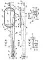
- la figure 1 est une vue en perspective partiellement éclatée et partiellement arrachée de la tête de câble optique selon l'invention,
- la figure 2 est une vue de côté avec arrachements partiels du boîtier chargeur de la tête de câble de la figure 1,
- les figures 3 et 4 sont deux vues, de la face avant et de la face arrière du boîtier-chargeur de la figure 2, données selon la flèche III et la ligne brisée IV-IV de cette figure 2,
- les figures 5 et 6 sont deux vues du même boîtier-chargeur, selon la ligne V-V et la flèche VI de la figure 2, la figure 6 étant en coupe partielle,
- la figure 7 est une vue en perspective de l'un des supports de connecteur optique de la tête de câble de la figure 1,
- la figure 8 est une vue de côté de ce support de connecteur optique de la figure 7,
- la figure 9 est une vue de dessous du support de connecteur optique selon la flèche IX de la figure 8,
- les figures 10 et 11 sont deux vues du support de connecteur optique, selon la ligne X-X et la flèche XI de la figure 9,
- la figure 12 est une vue en coupe partielle illustrant le boîtier-chargeur de la figure 2 avec l'un des supports de connecteur optique verrouillé dans son logement et un autre support du même type à peine engagé dans son logement.
- FIG. 1 is a partially exploded and partially cutaway perspective view of the optical cable head according to the invention,
- FIG. 2 is a side view with partial cutaway of the charger unit of the cable head of FIG. 1,
- FIGS. 3 and 4 are two views, of the front face and the rear face of the charger box of FIG. 2, given according to arrow III and the broken line IV-IV of this FIG. 2,
- FIGS. 5 and 6 are two views of the same charger box, along the line VV and the arrow VI of FIG. 2, FIG. 6 being in partial section,
- FIG. 7 is a perspective view of one of the optical connector supports of the cable head of FIG. 1,
- FIG. 8 is a side view of this optical connector support of FIG. 7,
- FIG. 9 is a bottom view of the optical connector support according to arrow IX in FIG. 8,
- FIGS. 10 and 11 are two views of the optical connector support, along the line XX and the arrow XI in FIG. 9,
- Figure 12 is a partial sectional view illustrating the charger unit of Figure 2 with one of the optical connector supports locked in its housing and another support of the same type barely engaged in its housing.
La tête optique illustrée dans la figure 1 comporte, montée dans un boîtier-chargeur 1, une pluralité de supports de connecteur optique identiques, tels que les deux supports de connecteur 3 visibles au niveau de l'arrachement repéré 1A pratiqué dans l'une des parois du boîtier-chargeur, l'un de ces deux supports de connecteur étant totalement engagé dans son logement du boîtier-chargeur et l'autre presque totalement hors de son logement.The optical head illustrated in FIG. 1 comprises, mounted in a
En regard du support de connecteur optique 3 représenté à peine engagé dans son logement du boîtier-chargeur 1, on voit que ce support de connecteur a un corps allongé formé d'un doigt creux 30. Ce doigt porte une pièce de raccordement 31 de forme cylindrique, montée au bout du doigt et est flanqué, à l'extrémité opposée, d'un support latéral 32 de lovage d'une longueur de fibre optique.Opposite the
Le boîtier-chargeur 1 a la forme générale d'un parallélépipède rectangle plat comportant une rangée de cavités telles que les deux cavités 10 visibles dans la partie arrachée, l'une de ces deux cavités étant celle servant de logement au support de connecteur optique représenté à peine engagé et l'autre au-dessus étant libre de tout support de ce type. Ces cavités sont ouvertes sur la face arrière repérée 1 B du boîtier pour le montage des supports de connecteur optique qu'elles reçoivent ; elles débouchent sur la face avant repérée 1C en des ouvertures circulaires 11, visibles pour les deux cavités visibles précitées, destinées à recevoir les pièces de raccordement 31 des supports de connecteur optique en place dans leur logement.The charger-
Dans la réalisation illustrée, le boîtier-chargeur peut recevoir dix supports de connecteur optique et comporte en conséquence dix cavités pour leur logement.In the illustrated embodiment, the charger unit can receive ten optical connector supports and consequently has ten cavities for their housing.
Le câble optique sur lequel est montée cette tête est illustré en 5. Dans la réalisation donnée, ce câble est un câble à dix fibres, il est du type à ruban plat ou jonc cylindrique ou à fibres indépendantes. Ce câble dégainé traverse un manchon ou boîtier plat 6, les fibres individuelles ou issues d'un jonc ou de rubans, alors libres, y sont regainées puis séparées en deux jeux identiques de cinq fibres 51 et 52 et fixées en 53 et 54 sur une plaque 12' de recouvrement partiel du fond du boîtier-chargeur 1 où entrent les fibres regainées telles que 55. Cette plaque de fond 12' ou, en variante équivalente, une plaque identique 12 de recouvrement partiel du dessus du boîtier-chargeur 1, définit sur le boîtier-chargeur l'entrée des dix fibres 55, appartenant ou reliées à celles du câble, qui se présentent en deux ensembles distincts de cinq fibres individuelles. Cette entrée des fibres dans le boîtier-chargeur 1 est indépendante de ses dix cavités.The optical cable on which this head is mounted is illustrated in 5. In the embodiment given, this cable is a cable with ten fibers, it is of the type with flat ribbon or cylindrical rod or with independent fibers. This unsheathed cable passes through a sleeve or flat box 6, the individual fibers or from a rod or ribbons, then free, are sheathed there and then separated into two identical sets of five
Dans la figure 1, pour la netteté du dessin seules deux des fibres 55 ont été reliées aux deux supports de connecteur optique visibles, tandis que les autres ont été volontairement sectionnées.In FIG. 1, for the sharpness of the drawing, only two of the
L'extrémité libre de chacune des fibres 55 est équipée d'un embout de connexion 56 visible sur la fibre montée dans le support de connecteur optique représenté à peine engagé dans son logement. Cet embout 56, étant en tant que tel de type connu, ne sera pas décrit en détail ; il sera par exemple du type à trois tiges de positionnement de l'extrémité de la fibre individuelle qu'il reçoit, tel que cité dans le préambule de la présente demande, ou d'un autre type équivalent.The free end of each of the
Depuis leur entrée dans le boîtier-chargeur 1, les fibres 55 des deux ensembles s'étendent en boucle libre latéralement dans le boîtier-chargeur, dans l'une et l'autre de ses deux grandes faces latérales telles que celle visible et repérée 1D, et sont lovées sur une longueur souhaitée, par exemple de 1 à 2 mm, sur le support latéral de lovage 32 des supports de connecteur optique, respectivement., Chacune des portions terminales des fibres 55 est alors engagée, depuis le support de lovage 32, dans le doigt creux 30 du support de connecteur optique concerné, tandis que l'embout de connexion 56 qui l'équipe s'enfiche dans la pièce de raccordement 31 montée en bout du doigt de ce support de connecteur.Since entering the
Une fois le support de connecteur optique en place dans son logement, c'est sa pièce de raccordement 31, déjà connectée à l'embout de l'une des fibres, côté intérieur au doigt, qui déborde sur la face avant 1C du boîtier-chargeur 1. Cette pièce de raccordement est ainsi prête à recevoir par enfichage un embout terminal d'une fibre extérieure (non illustrée) appartenant à un autre câble ou formant une entrée ou une sortie d'un appareillage adéquat, pour leur connexion. Les pièces de raccordement 31 constituent donc sur la face avant du boîtier des prises optiques sur les fibres individuelles du câble 5.Once the optical connector support is in place in its housing, it is its connecting
Deux plaques 13 et 13' de recouvrement partiel des grandes faces latérales du boîtier-chargeur viennent recouvrir les supports de lovage 32 des supports de connecteur optique et assurent la présentation finale de la tête de câble sous forme d'un boîtier classique d'appareillage. Ces plaques 13 et 13' sont maintenues par les plaques de fond et de dessus 12' et 12 à rebords repliés qui seront fixées par vis sur le boîtier-chargeur.Two
La description de la tête de câble optique est complétée en se reférant à cette figure 1 ou plus particulièrement aux figures 2 à 6 en ce qui concerne le boîtier-chargeur 1 représenté sans ses supports de connecteur optique et aux figures 7 à 11 en ce qui concerne l'un quelconque des supports de connecteur optique 3.The description of the optical cable head is supplemented with reference to this FIG. 1 or more particularly to FIGS. 2 to 6 as regards the
En regard des figures 1, 2 ou 5 notamment, on voit que le boîtier-chargeur 1 est formé par ur corps principal 14 ayant la forme d'un parallélépipède rectangle dans lequel est pratiquée la rangée de cavités 10. Ce corps principal 14 est muni, sensiblement sur la moitié avant, de deux flasques latéraux 15 et 16 s'étendant à l'extérieur, sur sa hauteur et sensiblement sur la moitié de sa longueur, depuis sa face avant 1C. Ces flasques ménagent, entre eux et le corps principal 14, deux ouïes latérales 17 et 17', servant de logements à l'un et l'autre des deux ensembles de fibres individuelles s'étendant en boucle libre entre leur entrée dans le boîtier-chargeur 1 et le support de lovage des supports de connecteur optique qui reçoivent ces fibres.With reference to FIGS. 1, 2 or 5 in particular, it can be seen that the
Pour chacun des supports de connecteur optique, le support de lovage 32 vient se positionner à l'extérieur du corps principal du boîtier-chargeur contre l'une ou l'autre de la moitié arrière de ses grandes parois latérales telles que 1 D. Les cavités 10 ouvertes sur la face arrière 1 B sont de ce fait également ouvertes en des fenêtres oblongues 19 ou 19' pratiquées depuis la face arrière 18 dans les parties des grandes parois latérales 1 D du corps 14, non recouvertes par les flasques 15 et 16. Pour la rangée de cavités 10, ces fenêtres 19, 19' sont pratiquées alternativement sur l'une et l'autre de ces grandes faces latérales 1 D respectivement; les supports de connecteur optique 3 chargés dans les cavités successives seront donc alternativement retournés de 180° de sorte que les supports de lovage 32 occupent, sur les surfaces latérales du boîtier sensiblement le double de la hauteur qui pourrait normalement leur être affectée en l'absence de retournement d'un support de connecteur optique sur deux.For each of the optical connector supports, the
Cette disposition donne la possibilité de lovage des fibres individuelles avec un rayon de courbure compatible avec les exigences de transmission d'information, sans pour autant aboutir à une tête de câble optique de hauteur exagérée. On précise, que dans le mode de réalisation, les supports de connecteur optique montés dans le boîtier-chargeur 1 sont disposés au pas de 42,5 mm et qu'aucun rayon de courbure des fibres individuelles sur leur support de lovage n'est inférieur à 40 mm.This arrangement gives the possibility of coiling individual fibers with a radius of curvature compatible with the requirements for transmitting information, without however leading to an optical cable head of exaggerated height. It is specified that in the embodiment, the optical connector supports mounted in the
Dans le corps principal 14'du boîtier-chargeur, les cavités 10 sont de section pratiquement identique à celle des doigts 30 des supports de connecteur optique qui viennent par glissement s'y logér. En regard des figures 2 et 4 notamment on voit que ces cavités 10 sont séparées les unes des autres par des cloisons internes 20, les parois inférieure et supérieure du corps principal limitant les cavités extrêmes de la rangée. Les cloisons internes 20 sont alternativement issues en totalité ou en partie d'usinage du corps principal 14. Une de ces cloisons sur deux s'étend d'un seul tenant depuis la face avant du boîtier-chargeur 1 jusqu'à sa face arrière tandis que les autres cloisons ne s'étendent que jusqu'à proximité de cette face arrière et sont associées à des pièces rapportées 21 fixées par des paires de vis ou rivets 22 sur les grandes parois latérales du boîtier-chargeur. Chacune des pièces rapportées 21 est équipée d'une paire de lames élastiques 23, 23' venant s'étendre dans l'une et l'autre des deux cavités que sépare la cloison concernée, notamment en l'absence de supports de connecteur optique dans ses cavités. Selon les figures 2 et 4, on voit que cinq des neufs cloisons internes 20 présentent une telle pièce rapportée 21. Ainsi chacune des dix cavités a sa lame élastique qui normalement s'étend à l'intérieur de la cavité en l'absence de support de connecteur optique, cette lame venant se rabattre contre la pièce 21 qui la porte lors de la mise en place dudit support. Le rôle de ces lames élastiques 23, 23' sera donné ultérieurement en regard de la figure 12.In the
Ces pièces rapportées 21 sont en outre munies d'une paire de trous taraudés 24 ou 24'. Ces trous taraudés serviront à la fixation finale par vis ou verrouillage des deux supports de connecteur optique logés dans les deux cavités séparées par la cloison comportant la pièce rapportée 21 considéré, ainsi qu'il sera indiqué plus clairement ci-après.These
En regard des figures 1 et 2, mais plus particulièrement des figures 3, 4 et 5, on voit que l'un des flasques 15 du boîtier-chargeur définit une rangée de guides, ici sous forme de glissières externes profilées en creux telles que 18, qui correspond à la rangée de supports de connecteur logés dans les cavités 10. Ces glissières seront avantageusement utilisées pour le maintien et le positionnement de boîtiers d'appareillage à raccorder sur la tête de câle optique.With reference to FIGS. 1 and 2, but more particularly to FIGS. 3, 4 and 5, it can be seen that one of the
Dans l'exemple choisi la tête de câble optique comportera sur le flasque 15 onze glissières 18 pour les dix supports de connecteur optique possibles logés dans les dix cavités. Cette disposition permet de n'équiper de glissières qu'un seul des flasques 15 et 16 tout en permettant un accrochage de boîtiers d'appareillage à gauche ou à droite de la tête de câble, par simple retournement de cette dernière.In the example chosen, the optical cable head will have eleven
En regard de ces mêmes figures ou de la figure 6, on voit que la moitié avant des faces supérieure et inférieure du boîtier-chargeur 1 sont équipées chacune d'un profilé de glissement ici sous forme d'une nervure longitudinale axiale 25 ou 25' et présentent chacune un moyen de positionnement réalisé sous forme d'une échancrure triangulaire 26 ou 26' pratiquée symétriquement par rapport à la nervure et dont la base aboutit sur la face avant du boîtier-chargeur. Bien que non représenté, on comprendra aisément que ces nervures 25 et 25' peuvent être utilisées pour la mise en place de la tête de câble optique entre deux supports équipés de glissières, tandis que ces échancrures 26 et 26' servent de pièges pour des ergots portés par les supports sur lesquels ils sont alignés avec les glissières et assurent alors le positionnement final de la tête de câble sur ces supports. Cette tête de câble sera fixée définitivement sur un bâti, poutre, cadre ou analogue, portant les supports, par vis montées par exemple dans des pattes de fixation telles que 27 ici portées par la partie arrière de l'une des grandes faces latérales.With reference to these same figures or to FIG. 6, it can be seen that the front half of the upper and lower faces of the
De la figure 1 et la figure 6, on voit également que la moitié arrière des faces supérieure et inférieure du boîtier-chargeur 1, représentées non recouvertes par les plaques de fond et de dessus 12' et 12, présentent chacune une nervure centrale en V28 ou 28', à pointe orientée vers la face arrière 1 B du boîtier-chargeur. Chacune de ces nervures en V28 et 28' matérialise de part et d'autre d'elle sous la plaque 12 ou 12' qui la coiffe, deux chemins séparés pour l'un et l'autre de deux ensembles de cinq fibres individuelles 55 qui pénètrent dans les deux ouïes latérales 17 et 17' du boîtier-chargeur 1.From Figure 1 and Figure 6, we also see that the rear half of the upper and lower faces of the
Dans la figure 6 également, dans laquelle l'une des pattes de fixation 27 a été représentée en coupe, on voit que cette patte porte le logement 29 pour une vis d'accrochage sur un bâti, une poutre ou un cadre extérieur.Also in FIG. 6, in which one of the fixing lugs 27 has been shown in section, it can be seen that this lug carries the
En regard du support de connecteur optique 3 représenté dans les figures 7 à 11, on voit que le doigt creux 30 est constitué par une lamelle rigide, de préférence métallique, repliée en U très allongé.Opposite the
La pièce de raccordement 31 est montée sur la base de U qu'elle traverse en débordant intérieurement et extérieurement du doigt pour l'enfichage de l'embout 56 de la fibre 55 à l'intérieur du doigt et l'enfichage d'un autre embout analogue d'une fibre extérieure, non illustrée, à raccorder à la fibre 55. Cette pièce de raccordement 31 est solidarisée au doigt par mise en butée sur la face extérieure de la base du U d'une collerette intermédiaire 33 qu'elle présente et par blocage au moyen d'un écrou 34 vissé sur une portion intermédiaire filetée 35, intérieure au doigt, que présente la pièce 31 au voisinage de la collerette. Des trous tels que 30a (figure 11) sont réalisés sur la base de U du support de connecteur optique 3 afin de pouvoir monter une pièce de raccordement 31 d'une autre conception que celle représentée ici.The connecting
Le support de lovage 32 est constitué essentiellement par une plaque 40 ayant ici la forme d'un rectangle à angles et petits côtés arrondis ou la forme générale d'une ellipse aplatie sur son petit axe. Cette forme illustrée permet le lovage de la fibre reçue avec un rayon .de courbure suffisant, compatible avec les exigences de transmission sur la fibre, et avec un encombrement minimal en hauteur sur le boîtier-chargeur. Bien entendu, en variante, ce support de lovage pourra être circulaire, le rayon de ce cercle devant respecter les exigences de transmission sur la fibre. En pratique, la forme de ce support de lovage sera issue d'un compromis réalisé entre son encombrement en hauteur, donc en définitive la hauteur du boîtier-chargeur, et sa facilité de réalisation, en général par moulage. On notera en regard de la forme circulaire possible de ce support de lovage que le boîtier-chargeur pourra dans ce cas être réduit en profondeur, c'est-à-dire selon la direction des cavités 10.The coiling
La plaque 40 est montée sur l'un des côtés du doigt, transversalement aux branches du U et sensiblement au niveau de leurs portions terminales. Elle est de hauteur maximale, correspondant à la longueur du petit axe de l'ellipse, voisine du double de la hauteur du doigt. Le support de lovage porte, sur la face de la plaque 40 tournée vers le doigt et dite face intérieure, deux pattes 36 et 37 venant l'une et l'autre s'insérer entre les branches du doigt profilée en U. Chacune de ces pattes permet d'assurer la fixation au moyen d'une paire de vis telles que 38 et 39, du support de lovage 32 sur l'une et l'autre des deux branches du doigt 30. Les portions de ces pattes, adjacentes à la plaque 40, forment également un chemin de glissement du support de connecteur optique sur l'un des bords longitudinaux de la fenêtre 19, 19' de la cavité qui reçoit ledit support.The
Le support de lovage 32 est à bord 41 doublement rabattu sur la face extérieure au doigt 30 de la plaque 40. Ce bord 41 doublement rabattu est interrompu pour définir des languettes périphériques distinctes désignées par cette même référence 41, ménageant entre elles des accès périphériques possibles tels que 42, pour la fibre 55 venant de l'extérieur du support de connecteur optique en l'occurence de l'une des ouïes latérales du boîtier-chargeur 1 (figure 1). Ces languettes 41 assurent donc .le maintien, quasiment sur la périphérie de la plaque 40, de la longueur voulue de fibre 55 reçue sur le support de lovage à travers l'un des accès 42, elles permettent aussi, un dégagement manuel aisé d'une partie de la longueur lovée, si nécessaire.The coiling
Ce support de lovage 32 présente aussi une fenêtre oblongue 43 pratiquée dans la plaque 40, constituant un autre accès pour la fibre 55, depuis la face extérieure de lovage de la fibre à la face intérieure en regard du doigt 30 et dans le doigt. Cette fenêtre 43 est positionnée en regard de l'espace intérieur entre les deux branches du doigt en U, elle est, ici, de largeur sensiblement égale à l'écartement entre ces deux branches. Avantageusement, de part et d'autre de la fenêtre des portions 41' ont été renforcées en épaisseur.This coiling
Pour le libre passage intérieur de la fibre 55 dans toute la longueur du doigt 30, la patte 36 de fixation du support, la plus intérieure dans le profilé en U du doigt, présente sur toute sa largeur une fente médiane 44. La portion terminale de la fibre 55, équipée de son embout de connexion 56 vient ainsi, à travers la fenêtre 43 et la fente 44 s'étendre jusqu'à la base du doigt en U pour l'enfichage de cet embout dans la pièce de raccordement 31.For the free internal passage of the
Dans la réalisation illustrée, le support de lovage 32 est positionné sur le doigt pour ne venir déborder que très légèrement du niveau donné par l'une des branches du doigt mais pour venir déborder très largement au-delà du niveau donné par l'autre branche.In the illustrated embodiment, the coiling
Bien entendu un positionnement différent de ce support de lovage sur le doigt pourra, en variante, être adopté.Of course, a different positioning of this coiling support on the finger could, as a variant, be adopted.
Le support de connecteur optique 3 comporte, en outre, un moyen de verrouillage dans le boîtier-chargeur décrit ci-avant. Ce moyen de verrouillage est constitué par une vis imperdable 45 montée avec une entretoise cylindrique 45' dans un étrier 46. L'étrier est fixé sur l'extrémité de l'une des branches du doigt 30 profilé en U, dans l'exemple illustré, la branche se trouvant sensiblement selon l'axe longitudinal médian de la plaque 40. Cet étrier 46 avec sa vis imperdable 45 constituent les pièces terminales du support de connecteur optique, à l'opposé de la pièce de raccordement ; la branche du doigt qui porte cet étrier est donc légèrement plus longue que l'autre, son extrémité déborde sur la longueur du support de lovage 32. Sur l'extrémité de cette branche, l'étrier 46 est monté au voisinage du bord longitudinal opposé à celui en regard du support de lovage, un oeil 47 est pratiqué au voisinage de l'autre bord longitudinal.The
Le verrouillage du support de connecteur optique logé dans le boîtier-chargeur se fera par fixation de la vis 45 dans le trou taraudé correspondant 24 ou 24' de la pièce 21 (figures 2 et 4), l'autre trou taraudé de cette même pièce 21 recevant la vis de fixation de l'un des deux supports de connecteur optique adjacents. Le retrait d'un support de connecteur optique 3, après son déverrouillage dé la pièce 21 sur laquelle il était fixé, se fait à l'aide d'un outil de préhension engagé dans l'oeil 47.The optical connector support housed in the charger box will be locked by fixing the
Le support de connecteur optique 3 comporte, aussi, une ouverture 48 pratiquée dans l'une des branches du doigt 30, au voisinage de la base de son profilé en U. Ainsi qu'il apparaît dans la figure 12 tout particulièrement, cette découpe 48 coopère avec l'une des lames élastiques 23 et 23' portées par la pièce 21 rapportée en bout de la cloison 20 interrompue. Cette découpe 48 et la lame 23 concernée forment, au cours du retrait du support de connecteur optique 3 symbolisé par la flèche R, une butée d'arrêt juste avant le dégagement final du support de connecteur optique de sa cavité 10. Au droit de cette ouverture, la lame élastique 23 n'est plus sollicitée et s'y engage. Son extrémité en butée contre l'un des bords de l'ouverture s'oppose au retrait définitif qui sera alors effectué avec l'aide d'un outil dégageant la lame élastique de l'ouverture, par contre lors de la mise en place du support de connecteur optique dans sa cavité au fur et à mesure de l'avancement de ce support l'autre bord de l'ouverture 48 repousse la lame élastique contre la pièce 21 qui la porte, de manière qu'elle ne fasse plus obstacle à cet avancement.The
Ce retrait aisé de l'un quelconque des supports de connecteur optique du boîtier chargeur, indépendamment des autres supports de connecteur optique permet le cas échéant, de venir effectuer une réparation sur l'un des supports de connecteur optique au niveau de son embout de connexion grâce à la réserve de fibre qu'il comporte, ceci sans manipulation à effectuer sur les autres supports de connecteur et donc sans interruption des liaisons établies sur lesdits supports.This easy removal of any of the optical connector supports from the charger box, independently of the other optical connector supports, makes it possible, if necessary, to carry out a repair on one of the optical connector supports at its connection end piece. thanks to the fiber reserve which it comprises, this without manipulation to be carried out on the other connector supports and therefore without interruption of the connections established on said supports.
La présente invention a été décrite en regard d'un mode de réalisation donné dans le dessin ci- annexé, il est évident que l'on pourra y apporter des modifications de détail ou remplacer certains moyens par d'autres équivalents sans pour autant sortir du cadre de l'invention.The present invention has been described with reference to an embodiment given in the accompanying drawing, it is obvious that it will be possible to make detailed modifications or replace certain means by other equivalents without departing from the part of the invention.
Claims (15)
Applications Claiming Priority (2)
| Application Number | Priority Date | Filing Date | Title |
|---|---|---|---|
| FR8213627 | 1982-08-04 | ||
| FR8213627AFR2531544B1 (en) | 1982-08-04 | 1982-08-04 | OPTICAL CABLE HEAD |
Publications (2)
| Publication Number | Publication Date |
|---|---|
| EP0101970A1 EP0101970A1 (en) | 1984-03-07 |
| EP0101970B1true EP0101970B1 (en) | 1987-03-04 |
Family
ID=9276634
Family Applications (1)
| Application Number | Title | Priority Date | Filing Date |
|---|---|---|---|
| EP83107609AExpiredEP0101970B1 (en) | 1982-08-04 | 1983-08-02 | Optical cable head |
Country Status (6)
| Country | Link |
|---|---|
| US (1) | US4585303A (en) |
| EP (1) | EP0101970B1 (en) |
| CA (1) | CA1231567A (en) |
| DE (1) | DE3370083D1 (en) |
| FR (1) | FR2531544B1 (en) |
| IE (1) | IE54524B1 (en) |
Families Citing this family (97)
| Publication number | Priority date | Publication date | Assignee | Title |
|---|---|---|---|---|
| FR2538918A1 (en)* | 1983-01-05 | 1984-07-06 | Telecommunications Sa | FIBER OPTIC CONNECTION AND BREWING BOX |
| DE3404613A1 (en)* | 1984-02-09 | 1985-08-14 | Siemens AG, 1000 Berlin und 8000 München | DEVICE FOR DETACHABLE COUPLING A LIGHT WAVE GUIDE TO AN OPTOELECTRONIC COMPONENT |
| US4630886A (en)* | 1984-04-16 | 1986-12-23 | At&T Bell Laboratories | Lightguide distributing unit |
| FR2566756B1 (en)* | 1984-06-27 | 1987-05-07 | Cit Alcatel | CABLE LOVING BOX |
| US4673246A (en)* | 1984-08-24 | 1987-06-16 | Pacific Bell | Patch unit for fiber optic distribution network |
| FR2570196B1 (en)* | 1984-09-10 | 1988-02-05 | Souriau & Cie | DEVICE FOR STORING THE EXTREME PARTS OF OPTICAL FIBERS AT THE BREAKING HEADS OF MULTIFIBER CABLES |
| FR2575020B1 (en)* | 1984-12-14 | 1987-02-13 | Nozick Jacques | DISTRIBUTOR FOR OPTICAL CABLES |
| FR2581769B1 (en)* | 1985-05-10 | 1988-08-26 | Pouyet Henri | DEVICE FOR STORING OPTICAL FIBERS |
| GB8514389D0 (en)* | 1985-06-07 | 1985-07-10 | Telephone Cables Ltd | Joint closure housing |
| GB8515779D0 (en)* | 1985-06-21 | 1985-07-24 | Gen Electric Co Plc | Optical fibre apparatus |
| US4765710A (en)* | 1985-07-30 | 1988-08-23 | Siemens Aktiengesellschaft | Distributing frame for optical waveguides and the like |
| DE3530162A1 (en)* | 1985-08-23 | 1987-03-05 | Rose Walter Gmbh & Co Kg | DEVICE FOR THE SPLICING OF LIGHT-WAVE CORE |
| FR2587127B1 (en)* | 1985-09-06 | 1987-10-23 | Valleix Paul | STRUCTURE FOR OPTICAL CONNECTIONS |
| US4792203A (en)* | 1985-09-17 | 1988-12-20 | Adc Telecommunications, Inc. | Optical fiber distribution apparatus |
| EP0222691B1 (en)* | 1985-11-12 | 1991-07-24 | KRONE Aktiengesellschaft | Device for the preservation of the fibres of glass fibre cables in the distribution assemblies of a telecommunication network |
| DE3540472A1 (en)* | 1985-11-12 | 1987-05-14 | Krone Ag | DEVICE FOR STORING THE FIBERS OF FIBERGLASS CABLES IN DISTRIBUTION DEVICES IN THE TELECOMMUNICATION NETWORK |
| FR2600781B1 (en)* | 1986-06-25 | 1991-05-03 | Constr Telephoniques | SUPPORT FOR FIBER OPTIC STORAGE CASSETTE |
| DE3636435A1 (en)* | 1986-10-25 | 1988-05-05 | Ant Nachrichtentech | Holder for splice magazine |
| US4824196A (en)* | 1987-05-26 | 1989-04-25 | Minnesota Mining And Manufacturing Company | Optical fiber distribution panel |
| DE3806136A1 (en)* | 1988-02-26 | 1989-09-07 | Rheydt Kabelwerk Ag | ARRANGEMENT AND METHOD FOR STOCKING OPTICAL Veins |
| US4865412A (en)* | 1988-04-18 | 1989-09-12 | Minnesota Mining And Manufacturing Company | Connector for splicing optical fiber cables |
| US4818055A (en)* | 1988-04-18 | 1989-04-04 | Minnesota Mining And Manufacturing Company | Optical fiber splice connector |
| US5071211A (en)* | 1988-12-20 | 1991-12-10 | Northern Telecom Limited | Connector holders and distribution frame and connector holder assemblies for optical cable |
| US4909583A (en)* | 1989-01-05 | 1990-03-20 | Hughes Aircraft Company | Method and apparatus for preserving modes in fiber optic connections requiring angular translation |
| US5013121A (en)* | 1989-06-29 | 1991-05-07 | Anton Mark A | Optical fiber storage container |
| JPH03116106A (en)* | 1989-08-15 | 1991-05-17 | Minnesota Mining & Mfg Co <3M> | Optical fiber terminating module |
| US5052775A (en)* | 1989-08-15 | 1991-10-01 | Minnesota Mining And Manufacturing Company | Optical fiber module termination array and panel |
| US4986626A (en)* | 1989-08-15 | 1991-01-22 | Minnesota Mining And Manufacturing Company | Optical fiber termination module |
| US4986762A (en)* | 1989-08-15 | 1991-01-22 | Minnesota Mining And Manufacturing Company | Termination module for use in an array of modules |
| US4971421A (en)* | 1989-09-29 | 1990-11-20 | Reliance Comm/Tec Corporation | Fiber optic splice and patch enclosure |
| US5121454A (en)* | 1989-11-24 | 1992-06-09 | Nippon Telegraph And Telephone Corporation | Optical connector |
| EP0474091B1 (en)* | 1990-09-03 | 1996-11-06 | Reichle + De-Massari AG Elektro-Ingenieure | Pothead device for signal transmission cables, particularly for glass fibres cables |
| DE4142586C2 (en)* | 1991-12-21 | 1994-07-28 | Rose Walter Gmbh & Co Kg | Connection and branch sleeve for telecommunication cables, coaxial cables or fiber optic cables |
| DE4229884C2 (en)* | 1992-09-04 | 1994-06-16 | Krone Ag | Device for storing the single and loose tubes of fiber optic cables in distribution facilities for telecommunications and data technology |
| CA2081608C (en)* | 1992-10-28 | 1998-05-05 | Joseph Octave Regis Morin | Distribution frame and optical connector holder combination |
| DE4322142C2 (en)* | 1993-07-02 | 1995-06-01 | Siemens Ag | Cable storage module for fiber optic cables |
| GB9318654D0 (en)* | 1993-09-08 | 1993-10-27 | Raychem Sa Nv | Optical fibre organizer |
| DE4334022C1 (en)* | 1993-10-06 | 1995-03-02 | Rose Walter Gmbh & Co Kg | Device for receiving splice cassettes for optical fibers, especially in cable sockets |
| TW232757B (en) | 1994-01-21 | 1994-10-21 | Adc Telecommunications Inc | High-density fiber distribution frame |
| US5825960A (en)* | 1996-04-30 | 1998-10-20 | The Whitaker Corporation | Fiber optic management system |
| US5975769A (en)* | 1997-07-08 | 1999-11-02 | Telect, Inc. | Universal fiber optic module system |
| US5946440A (en)* | 1997-11-17 | 1999-08-31 | Adc Telecommunications, Inc. | Optical fiber cable management device |
| US6201919B1 (en) | 1998-12-16 | 2001-03-13 | Adc Telecommunications, Inc | Fiber distribution frame |
| US6408124B1 (en) | 2000-09-21 | 2002-06-18 | Adc Telecommunications, Inc. | Cable storage cartridge |
| US6625374B2 (en) | 2001-03-07 | 2003-09-23 | Adc Telecommunications, Inc. | Cable storage spool |
| FR2832226B1 (en)* | 2001-11-13 | 2004-10-22 | Nexans | OPTICAL FIBER DISTRIBUTION AND CONNECTION MODULE FOR AN OPTICAL DISTRIBUTOR |
| US6591051B2 (en) | 2001-11-16 | 2003-07-08 | Adc Telecommunications, Inc. | Fiber termination block with angled slide |
| US7120347B2 (en)* | 2004-01-27 | 2006-10-10 | Corning Cable Systems Llc | Multi-port optical connection terminal |
| US7013074B2 (en)* | 2004-02-06 | 2006-03-14 | Corning Cable Systems Llc | Optical connection closure having at least one connector port |
| DE102006013951B4 (en)* | 2006-03-27 | 2010-05-12 | Dornier Medtech Laser Gmbh | light guide |
| US7542649B1 (en) | 2008-02-27 | 2009-06-02 | Ofs Fitel Llc | Optical fiber line card assembly |
| WO2010059623A1 (en) | 2008-11-21 | 2010-05-27 | Adc Telecommunications, Inc. | Fiber optic telecommunications module |
| CN102870021B (en) | 2010-03-02 | 2015-03-11 | 蒂安电子服务有限责任公司 | Fibre-optic telecommunication module |
| WO2012149020A2 (en) | 2011-04-25 | 2012-11-01 | Adc Telecommunications, Inc. | Rack and chassis for fiber optic sliding adapter modules |
| US9417418B2 (en) | 2011-09-12 | 2016-08-16 | Commscope Technologies Llc | Flexible lensed optical interconnect device for signal distribution |
| US8770861B2 (en) | 2011-09-27 | 2014-07-08 | Tyco Electronics Corporation | Outside plant termination enclosure |
| US9002166B2 (en) | 2011-10-07 | 2015-04-07 | Adc Telecommunications, Inc. | Slidable fiber optic connection module with cable slack management |
| US9170391B2 (en) | 2011-10-07 | 2015-10-27 | Adc Telecommunications, Inc. | Slidable fiber optic connection module with cable slack management |
| RU2611105C2 (en) | 2011-10-07 | 2017-02-21 | Адс Телекоммьюникейшнз, Инк. | Fibre-optic cartridge, system and method |
| CN103975264B (en) | 2011-10-07 | 2015-09-16 | Adc电信公司 | Slidable fiber optic connection module with cable slack management |
| US9075203B2 (en) | 2012-01-17 | 2015-07-07 | Adc Telecommunications, Inc. | Fiber optic adapter block |
| US9195021B2 (en) | 2012-09-21 | 2015-11-24 | Adc Telecommunications, Inc. | Slidable fiber optic connection module with cable slack management |
| US10082636B2 (en) | 2012-09-21 | 2018-09-25 | Commscope Technologies Llc | Slidable fiber optic connection module with cable slack management |
| US9146374B2 (en) | 2012-09-28 | 2015-09-29 | Adc Telecommunications, Inc. | Rapid deployment packaging for optical fiber |
| NZ706687A (en) | 2012-09-28 | 2017-09-29 | Adc Telecommunications Inc | Fiber optic cassette |
| US9223094B2 (en) | 2012-10-05 | 2015-12-29 | Tyco Electronics Nederland Bv | Flexible optical circuit, cassettes, and methods |
| CN105074525A (en) | 2013-01-29 | 2015-11-18 | 泰科电子瑞侃有限公司 | Fiber Distribution System |
| US9128262B2 (en) | 2013-02-05 | 2015-09-08 | Adc Telecommunications, Inc. | Slidable telecommunications tray with cable slack management |
| WO2014133943A1 (en) | 2013-02-27 | 2014-09-04 | Adc Telecommunications, Inc. | Slidable fiber optic connection module with cable slack management |
| US9435975B2 (en) | 2013-03-15 | 2016-09-06 | Commscope Technologies Llc | Modular high density telecommunications frame and chassis system |
| EP2989496B1 (en) | 2013-04-24 | 2019-06-12 | CommScope Connectivity Belgium BVBA | Universal mounting mechanism for mounting a telecommunications chassis to a telecommunications fixture |
| AP2015008820A0 (en) | 2013-04-24 | 2015-10-31 | Adc Czech Republic Sro | Optical fiber distribution system |
| WO2015116672A1 (en) | 2014-01-28 | 2015-08-06 | Adc Telecommunications, Inc. | Slidable fiber optic connection module with cable slack management |
| US9494758B2 (en) | 2014-04-03 | 2016-11-15 | Commscope Technologies Llc | Fiber optic distribution system |
| US9690065B2 (en) | 2014-09-12 | 2017-06-27 | Panduit Corp. | High density fiber enclosure and method |
| WO2016094331A1 (en) | 2014-12-10 | 2016-06-16 | Commscope Technologies Llc | Fiber optic cable slack management module |
| RU2583998C1 (en)* | 2015-01-20 | 2016-05-20 | Борис Алексеевич Хозяинов | Device for installation of switching cords in telecommunication rack (box) |
| AU2016239875C1 (en) | 2015-04-03 | 2021-06-24 | CommScope Connectivity Belgium BVBA | Telecommunications distribution elements |
| WO2017184501A1 (en) | 2016-04-19 | 2017-10-26 | Commscope, Inc. Of North Carolina | Door assembly for a telecommunications chassis with a combination hinge structure |
| ES2851948T3 (en) | 2016-04-19 | 2021-09-09 | Commscope Inc North Carolina | Telecom rack with slide out trays |
| US10215944B2 (en) | 2016-06-30 | 2019-02-26 | Panduit Corp. | Modular fiber optic tray |
| WO2018226959A1 (en) | 2017-06-07 | 2018-12-13 | Commscope Technologies Llc | Fiber optic adapter and cassette |
| US11409068B2 (en) | 2017-10-02 | 2022-08-09 | Commscope Technologies Llc | Fiber optic circuit and preparation method |
| US11385429B2 (en) | 2017-10-18 | 2022-07-12 | Commscope Technologies Llc | Fiber optic connection cassette |
| US11852882B2 (en) | 2018-02-28 | 2023-12-26 | Commscope Technologies Llc | Packaging assembly for telecommunications equipment |
| WO2019204317A1 (en) | 2018-04-16 | 2019-10-24 | Commscope Technologies Llc | Adapter structure |
| US11635578B2 (en) | 2018-04-17 | 2023-04-25 | CommScope Connectivity Belgium BVBA | Telecommunications distribution elements |
| PL3844973T3 (en) | 2018-08-31 | 2025-03-03 | CommScope Connectivity Belgium BVBA | Frame assemblies for optical fiber distribution elements |
| WO2020043914A1 (en) | 2018-08-31 | 2020-03-05 | CommScope Connectivity Belgium BVBA | Frame assemblies for optical fiber distribution elements |
| EP3844547A1 (en) | 2018-08-31 | 2021-07-07 | CommScope Connectivity Belgium BVBA | Frame assemblies for optical fiber distribution elements |
| EP3845044B1 (en) | 2018-08-31 | 2023-02-15 | CommScope Connectivity Belgium BVBA | Frame assemblies for optical fiber distribution elements |
| EP3844546A1 (en) | 2018-08-31 | 2021-07-07 | CommScope Connectivity Belgium BVBA | Frame assemblies for optical fiber distribution elements |
| WO2020084012A1 (en) | 2018-10-23 | 2020-04-30 | CommScope Connectivity Belgium BVBA | Frame assemblies for optical fiber distribution elements |
| EP3914947A1 (en) | 2019-01-25 | 2021-12-01 | CommScope Connectivity Belgium BVBA | Frame assemblies for optical fiber distribution elements |
| WO2021148544A1 (en) | 2020-01-22 | 2021-07-29 | CommScope Connectivity Belgium BVBA | Cable termination units for optical fiber distribution elements |
| US12099246B2 (en) | 2020-01-24 | 2024-09-24 | CommScope Connectivity Belgium BVBA | Telecommunications distribution elements |
| US12339511B2 (en) | 2020-03-31 | 2025-06-24 | Commscope Technologies Llc | Fiber optic cable management systems and methods |
Family Cites Families (7)
| Publication number | Priority date | Publication date | Assignee | Title |
|---|---|---|---|---|
| US4167303A (en)* | 1977-07-28 | 1979-09-11 | Amp Incorporated | Light transmitting fiber cable connector |
| US4217030A (en)* | 1978-07-18 | 1980-08-12 | Bell Telephone Laboratories, Incorporated | Fiberoptic-electronic connector assembly |
| US4266853A (en)* | 1979-03-12 | 1981-05-12 | Northern Telecom Limited | Device for organizing optical fibers and the like |
| FR2493535A1 (en)* | 1980-10-31 | 1982-05-07 | Socapex | END CAP FOR OPTICAL FIBER CONNECTOR AND CONNECTOR PROVIDED WITH SUCH A TIP |
| US4428645A (en)* | 1981-01-28 | 1984-01-31 | Gk Technologies, Incorporated | Cable accumulator |
| DE3118173A1 (en)* | 1981-05-08 | 1982-11-25 | Philips Kommunikations Industrie AG, 8500 Nürnberg | Pressurised cable arrangement containing optical fibres and having an in-line (straight) cable closure |
| NL8102309A (en)* | 1981-05-12 | 1982-12-01 | Philips Nv | PLUG CONNECTION FOR COUPLING AT LEAST A LIGHT-CONDUCTING FIBER WITH A FURTHER OPTICAL ELEMENT. |
- 1982
- 1982-08-04FRFR8213627Apatent/FR2531544B1/ennot_activeExpired
- 1983
- 1983-07-29IEIE1813/83Apatent/IE54524B1/ennot_activeIP Right Cessation
- 1983-08-02EPEP83107609Apatent/EP0101970B1/ennot_activeExpired
- 1983-08-02DEDE8383107609Tpatent/DE3370083D1/ennot_activeExpired
- 1983-08-03CACA000433744Apatent/CA1231567A/ennot_activeExpired
- 1983-08-04USUS06/520,282patent/US4585303A/ennot_activeExpired - Fee Related
Also Published As
| Publication number | Publication date |
|---|---|
| FR2531544A1 (en) | 1984-02-10 |
| DE3370083D1 (en) | 1987-04-09 |
| FR2531544B1 (en) | 1985-01-25 |
| US4585303A (en) | 1986-04-29 |
| IE831813L (en) | 1984-02-04 |
| CA1231567A (en) | 1988-01-19 |
| EP0101970A1 (en) | 1984-03-07 |
| IE54524B1 (en) | 1989-11-08 |
Similar Documents
| Publication | Publication Date | Title |
|---|---|---|
| EP0101970B1 (en) | Optical cable head | |
| FR2531576A1 (en) | CONNECTION AND OPTO-ELECTRONIC INTERFACE | |
| EP0051510B1 (en) | Optical fibres positioning device in a piece forming ferrule destined to connect two transmission cables by optical fibres | |
| EP0429036B1 (en) | Metallic housing for electrical connector | |
| FR2538918A1 (en) | FIBER OPTIC CONNECTION AND BREWING BOX | |
| EP1224719A1 (en) | Device for guiding at least a flexible elongated element such as a cable or the like, with substantially closed contour | |
| FR2734651A1 (en) | FIBER OPTIC CONNECTION BOX | |
| EP2775334B1 (en) | Device comprising a plurality of boxes for connecting and/or storing cable or cable fibre | |
| FR2888683A1 (en) | ECONESS FOR CONNECTING CABLE TRUNCTIONS | |
| FR2898733A1 (en) | TERMINAL BLOCK OF INTERCONNECTION. | |
| FR3084781A1 (en) | ELECTRICAL EQUIPMENT SUPPORT AND ASSOCIATED ELECTRICAL EQUIPMENT | |
| FR2501381A1 (en) | DEVICE FOR FIELD CONNECTION OF TWO FIBER OPTIC TRANSMISSION CABLES | |
| FR2777129A1 (en) | WIRING CHUTE AND ACCESSORY LIKELY TO BE MOUNTED ON SUCH A WIRING CHUTE | |
| WO2013007936A2 (en) | Pivoting splice plate for connecting segments of a wire-based cable tray | |
| EP2068186A1 (en) | Optical socket for telecommunication network | |
| EP0712018B1 (en) | Cassette for the housing and protection of an optical fibre and installation for the storage of optical fibres | |
| FR3060101A1 (en) | DEVICE FOR CONNECTING LUMINAIRE | |
| EP2592426B1 (en) | Sensor for measuring a current in an electric cable | |
| FR2953655A1 (en) | Fastening device for fixing of electric accessory e.g. distribution box, on cable rack of wire, has locking units formed on plate and associated to each hook to maintain corresponding wires engaged in hooks | |
| FR2688897A1 (en) | Optical connection device | |
| CA1193125A (en) | Single optic fiber connector | |
| CA2319772A1 (en) | Device for connecting two optical fibres with axial retaining means and unlocking key | |
| EP0098190B1 (en) | Connecting and aligning apparatus for two optical-fibre ferrules having a v-shaped cross-section | |
| EP2768098B1 (en) | Splice plate for mesh cable trays sections | |
| EP0146471A2 (en) | Apparatus and method for the semi-permanent connection of optical fibres |
Legal Events
| Date | Code | Title | Description |
|---|---|---|---|
| PUAI | Public reference made under article 153(3) epc to a published international application that has entered the european phase | Free format text:ORIGINAL CODE: 0009012 | |
| AK | Designated contracting states | Designated state(s):BE DE FR GB IT LU NL SE | |
| 17P | Request for examination filed | Effective date:19840823 | |
| RAP1 | Party data changed (applicant data changed or rights of an application transferred) | Owner name:ALCATEL | |
| 17Q | First examination report despatched | Effective date:19860520 | |
| GRAA | (expected) grant | Free format text:ORIGINAL CODE: 0009210 | |
| AK | Designated contracting states | Kind code of ref document:B1 Designated state(s):BE DE FR GB IT LU NL SE | |
| REF | Corresponds to: | Ref document number:3370083 Country of ref document:DE Date of ref document:19870409 | |
| ITF | It: translation for a ep patent filed | ||
| PLBE | No opposition filed within time limit | Free format text:ORIGINAL CODE: 0009261 | |
| STAA | Information on the status of an ep patent application or granted ep patent | Free format text:STATUS: NO OPPOSITION FILED WITHIN TIME LIMIT | |
| 26N | No opposition filed | ||
| PGFP | Annual fee paid to national office [announced via postgrant information from national office to epo] | Ref country code:LU Payment date:19910607 Year of fee payment:9 | |
| EPTA | Lu: last paid annual fee | ||
| PG25 | Lapsed in a contracting state [announced via postgrant information from national office to epo] | Ref country code:LU Free format text:LAPSE BECAUSE OF NON-PAYMENT OF DUE FEES Effective date:19920802 | |
| PGFP | Annual fee paid to national office [announced via postgrant information from national office to epo] | Ref country code:DE Payment date:19930519 Year of fee payment:11 | |
| PGFP | Annual fee paid to national office [announced via postgrant information from national office to epo] | Ref country code:SE Payment date:19930521 Year of fee payment:11 | |
| PGFP | Annual fee paid to national office [announced via postgrant information from national office to epo] | Ref country code:GB Payment date:19930526 Year of fee payment:11 | |
| PGFP | Annual fee paid to national office [announced via postgrant information from national office to epo] | Ref country code:FR Payment date:19930527 Year of fee payment:11 | |
| PGFP | Annual fee paid to national office [announced via postgrant information from national office to epo] | Ref country code:BE Payment date:19930616 Year of fee payment:11 | |
| ITTA | It: last paid annual fee | ||
| PGFP | Annual fee paid to national office [announced via postgrant information from national office to epo] | Ref country code:NL Payment date:19930831 Year of fee payment:11 | |
| PG25 | Lapsed in a contracting state [announced via postgrant information from national office to epo] | Ref country code:GB Effective date:19940802 | |
| PG25 | Lapsed in a contracting state [announced via postgrant information from national office to epo] | Ref country code:SE Effective date:19940803 | |
| PG25 | Lapsed in a contracting state [announced via postgrant information from national office to epo] | Ref country code:BE Effective date:19940831 | |
| EAL | Se: european patent in force in sweden | Ref document number:83107609.6 | |
| BERE | Be: lapsed | Owner name:ALCATEL Effective date:19940831 | |
| PG25 | Lapsed in a contracting state [announced via postgrant information from national office to epo] | Ref country code:NL Effective date:19950301 | |
| GBPC | Gb: european patent ceased through non-payment of renewal fee | Effective date:19940802 | |
| NLV4 | Nl: lapsed or anulled due to non-payment of the annual fee | ||
| PG25 | Lapsed in a contracting state [announced via postgrant information from national office to epo] | Ref country code:FR Effective date:19950428 | |
| PG25 | Lapsed in a contracting state [announced via postgrant information from national office to epo] | Ref country code:DE Effective date:19950503 | |
| EUG | Se: european patent has lapsed | Ref document number:83107609.6 | |
| REG | Reference to a national code | Ref country code:FR Ref legal event code:ST |