EP0098192B1 - Multiplexing device for combining two frequency bands - Google Patents
Multiplexing device for combining two frequency bandsDownload PDFInfo
- Publication number
- EP0098192B1 EP0098192B1EP83401195AEP83401195AEP0098192B1EP 0098192 B1EP0098192 B1EP 0098192B1EP 83401195 AEP83401195 AEP 83401195AEP 83401195 AEP83401195 AEP 83401195AEP 0098192 B1EP0098192 B1EP 0098192B1
- Authority
- EP
- European Patent Office
- Prior art keywords
- band
- guide
- polarization
- hole
- coupling
- Prior art date
- Legal status (The legal status is an assumption and is not a legal conclusion. Google has not performed a legal analysis and makes no representation as to the accuracy of the status listed.)
- Expired
Links
Images
Classifications
- H—ELECTRICITY
- H01—ELECTRIC ELEMENTS
- H01P—WAVEGUIDES; RESONATORS, LINES, OR OTHER DEVICES OF THE WAVEGUIDE TYPE
- H01P1/00—Auxiliary devices
- H01P1/20—Frequency-selective devices, e.g. filters
- H01P1/213—Frequency-selective devices, e.g. filters combining or separating two or more different frequencies
- H01P1/2131—Frequency-selective devices, e.g. filters combining or separating two or more different frequencies with combining or separating polarisations
- H—ELECTRICITY
- H01—ELECTRIC ELEMENTS
- H01P—WAVEGUIDES; RESONATORS, LINES, OR OTHER DEVICES OF THE WAVEGUIDE TYPE
- H01P1/00—Auxiliary devices
- H01P1/16—Auxiliary devices for mode selection, e.g. mode suppression or mode promotion; for mode conversion
- H01P1/161—Auxiliary devices for mode selection, e.g. mode suppression or mode promotion; for mode conversion sustaining two independent orthogonal modes, e.g. orthomode transducer
Definitions
- the present inventionrelates to a multiplexing device for multiplexing two frequency bands B1, B2, where the frequencies of B1 are lower than the frequencies of B2, comprising, from the antenna access intended to be coupled to an antenna, a first polarization duplexer with a common guide passing bands B1 and B2 and a second polarization duplexer relating to band B2.
- the present inventionrelates, in particular, to a dual-band multiplexer constituted by the above-mentioned multiplexing device; it also relates to a multiplexer intended for the multiplexing of more than two frequency bands and which comprises a multiplexing device according to the invention.
- Multiplexersmaking it possible to group several frequency bands on the same antenna for a long time to cover the needs of the terrestrial and space radio-relay system. These multiplexers are of the two-band, three-band and more types. The polarizations of the waves are either straight or circular.
- duplexershave one thing in common: their mechanical complexity resulting in a high cost price.
- the duplexers of the other bandsare complicated; in fact, they require, for example, two directional couplers with total coupling, in series, relating respectively to the two polarizations of the wave to be transmitted in the band considered, or else they require, from four coupling holes distributed at 90 ° from each other around a common guide, a symmetrical structure formed by two pairs of guides, the guides of a pair arriving on two opposite holes and having to be joined together to form the access relating to one of the two polarizations.
- These known duplexersare also expensive because they use expensive filters in the access guides of the different bands.
- the object of the present inventionis, in particular, to reduce the aforementioned drawbacks while providing the same technical performance.
- a network for combining radio systems at 4, 6 and 11 kmcdescribes a network for combining radio systems in three frequency bands respectively: 3.7 to 4.2 GHz; 5.925 to 6.425 GHz; and 10.7 to 11.7 GHz, a common antenna making it possible to transmit and receive these three frequency bands, and to operate with two polarizations of these waves.
- This networkdistributes the six signals (two polarizations in each of the three frequency bands) to different gates, using a series of directional couplers.
- This first square section waveguideis then reduced to a second dominant mode square section guide to let pass the band from 5.925 to 6.425 GHz, two directional couplers making it possible to extract the two polarizations in this frequency band.
- This second guide with square sectionis further reduced in size and a network makes it possible to extract the two polarizations in the frequency band 10.7 to 11.7 GHz.
- the inventionprovides a multiplexing device for multiplexing two frequency bands B1, B2, where the frequencies of B1 are lower than the frequencies of B2, comprising, from the antenna access, intended to be coupled to an antenna, a first polarization duplexer with a common guide passing the bands B1 and B2 and a second polarization duplexer relating to the band B2, said common guide being pierced with lateral openings constituting coupling holes turned 90 ° around the common guide, two coupling guides turned 90 ° around the common guide, two rectangular guides respectively leading to these holes, at least one resonator tuned to a frequency of the band B2 being placed in each of the holes, characterized in that the first duplexer comprises: two successive sections of the common guide each pierced with a single coupling hole in which is placed at least one of said resonators; and, seen from the antenna access, a first and a second filter respectively placed between the first and the second encountered hole and between the second encountered hole and the second duplexer and constituting respectively two short-circuit
- the example which will be describedis a multiplexing device making it possible to pass the 4 GHz (3.7-4.2 GHz) and 6 GHz (5.925-6.425 GHz) bands, each of these two bands comprising two orthogonal or linear polarizations. , either cir eyepieces.
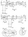
- Figure 1shows the multiplexing device seen from the side;
- FIG. 2also shows the multiplexing device seen from the side but turned 90 ° relative to.
- Figure 1shows the multiplexing device seen from the side;
- FIG. 2also shows the multiplexing device seen from the side but turned 90 ° relative to.
- Figure 1shows the multiplexing device seen from the side;
- FIG. 2also shows the multiplexing device seen from the side but turned 90 ° relative to.
- FIGS. 1 and 2show, in series from an access A intended to be coupled to an antenna, a first polarization duplexer, D1, relating to the 4 GHz band, a transition from round guide to round guide, Tr, and a second polarization duplexer, D2, relating to the 6 GHz band.
- the duplexer, D1 of the 4 GHz bandcomprises a common guide, G1-G2, one of the accesses of which constitutes access A and the other access of which is joined to the larger of the two openings of the transition Tr.
- the common guide G1-G2is a circular guide with an internal diameter equal to 54 mm, and which therefore allows the passage of the bands 4 and 6 GHz.
- an access guide g1intended for one of the two orthogonal polarizations of the 4 GHz band which will be called the first polarization.
- the guide g1is integral, at one of its ends, with the common guide section G1 and at its second end which constitutes the access A1 of the first polarization.
- the access guide g1is a rectangular guide whose short sides are perpendicular to the plane of Figure 1; this guide includes a transition zone between the access A1 and a straight line XX shown in broken lines in FIG. 1; this transition zone allows to pass from an opening of 58 x 29 mm on the access A1 to an internal section of 58 x 14.5 mm between the line XX and the hole T1, in order to have a good adaptation between the standard guide (58 x 29 mm), to be connected to access A ,, and the common guide G1-G2. Also to improve the adaptation, the hole T1 is provided with an iris Ir 39 mm long by 4 mm high, of which an enlarged view is given in FIG. 3.
- the iris Irhas its long sides parallel to the long sides of the access guide gl.
- two linear resonators R1, R2(see FIG. 3) whose resonant frequency is located in the 6 GHz band and whose role is, on the one hand, to prevent the energy of the 6 GHz band to pass in the access guide and, on the other hand, to let pass the energy of the band 4 GHz.
- the resonators R1, R2each consist of a metal strip one tenth of a millimeter thick and 1 mm wide, in the form of a square: they are arranged in the plane of the iris, and the largest side of the square, which measures 7 mm, is parallel to the long sides of the iris.
- a quasi-optical filter q1-q2is arranged in the common guide section G1, between the hole T1 and the common guide section G2.
- This filterconsists of two elements, q1 and q2, which, as shown in Figure 4, are each formed of a substrate S on which is placed a dipole d; the substrate S is made of polytetrafluoroethylene (also known under the trademark "teflon”) and the dipole d is made of copper and is deposited on the substrate S by a printed circuit technique.
- the dipoleis 36 mm long and 1 mm wide.
- the elements q1 and q2are arranged transversely in the guide section G1 and the dipole d is oriented, for each of the elements q1 and q2, so as to be parallel to the short sides of the access guide g1, that is to say say perpendicular to the plane of FIG. 1.
- the dipoles d of the elements q1 and q2, -whose resonance frequency is included in the 4 GHz bandbehave like short circuits for the part of the wave of the band 4 GHz having the first polarization, that is to say for the wave relating to the access A1 and whose polarization is perpendicular to the plane of FIG. 1.
- the assembly G1-g1Seen from the antenna access A, the assembly G1-g1 which has just been described is followed by an identical assembly G2-g2, the common guide section of which, G2, is connected in the extension of the section G1 and of which the access guide g2, relating to the part of the wave of the 4 GHz band having the second polarization, is directed perpendicular to the plane of FIG. 1.
- the elements q1, q2 and with the reference XX of the assembly G1- g1correspond, in the set G2-g2 the elements q3, q4 which form a quasi-optical filter and the marks X'X 'which indicate where is located (between an access A2 of the set G2-g2 and the line X 'X') the transition zone of the guide g2 corresponding to that of the guide g1.
- the set G2-g2being orthogonal to the set G1-g1, the dipoles d (see figure 4) of the filter elements q3 and q4 are placed parallel to the plane of figure 1 and therefore parallel to the small sides of the access guide g1, they therefore behave like short-circuits for the part of the wave of the 4 GHz band having the second polarization and reflect it towards the hole T2 for coupling the guide g2 on the guide section G2.
- the distance between the coupling holes T1 and T2must be at least of the order of magnitude of the maximum wavelength in the 4 GHz band so as to avoid that, in this frequency band, two polarizations of the wave do not react one on the other.
- the transition from round guide to round guide, Trmakes it possible to pass from the diameter 54 mm of the common guide G1-G2 which lets the bands 4 and 6 GHz pass, to the diameter 34 mm of the common guide G of the duplexer D2, which lets the band pass 6 GHz but not the 4 GHz band.
- the D2 duplexer in the 6 GHz bandincludes. connected to its common guide G, two orthogonal guides respectively relating to the two polarizations of the wave in the 6 GHz band: a access guide g3, of internal section 34.85 x 15.8 mm, located perpendicular to the common guide G and to the plane of FIG. 1, and an access guide g4 located in the extension of the circular common guide G and making a transition between this circular guide and a rectangular opening of 34.85 x 15.8 mm.
- the duplexer D2also comprises, in the guide G, substantially between the guides g3 and g4, a short-circuit strip, L, parallel to the plane of FIG.
- the ends of the guides g3 and g4 opposite the guide Gconstitute the access A3 and A4 of the duplexer D2 relating to the two linear polarizations of the wave in the 6 GHz band.
- the described multiplexing devicecan easily be used as a model, with modifications within the reach of those skilled in the art, for multiplexing, for example, the bands 11 and 14 GHz or 18 and 28 GHz.
- a duplexer of the type of the D1 duplexercan be mounted between the antenna and the D1 duplexer, i.e. with one end of its common guide coupled to the antenna and the other end connected to the access A of FIGS. 1 and 2 by a transition from round guide to round guide.
- the common guides of the duplexerscan be of square section, see rectangular.
- the multiplexing devicecan, as mentioned above, operate in circular polarization; it suffices to add to it a polarizer connected between the antenna access A (FIGS. 1 and 2) and the antenna and operating in the 4 and 6 GHz bands.
- the present inventionis intended, in particular, for frequency reuse multiplexers, that is to say multiplexers such that the two orthogonal polarizations of the same wave are used as separate information carriers.
- the inventioncan be used in the antennas of earth stations both for the frequency bands of space communications and for all the bands of terrestrial and tropospheric radio-relay systems.
Landscapes
- Waveguide Switches, Polarizers, And Phase Shifters (AREA)
- Waveguide Aerials (AREA)
- Control Of Motors That Do Not Use Commutators (AREA)
- Variable-Direction Aerials And Aerial Arrays (AREA)
- Filters And Equalizers (AREA)
- Amplifiers (AREA)
- Transmitters (AREA)
- Transceivers (AREA)
Abstract
Description
Translated fromFrenchLa présente invention concerne un dispositif de multiplexage pour multiplexer deux bandes de fréquences B1, B2, où les fréquences de B1 sont inférieures aux fréquences de B2, comportant, à partir de l'accès d'antenne destiné à être couplé à une antenne, un premier duplexeur de polarisation avec un guide commun passant les bandes B1 et B2 et un second duplexeur de polarisation relatif à la bande B2.The present invention relates to a multiplexing device for multiplexing two frequency bands B1, B2, where the frequencies of B1 are lower than the frequencies of B2, comprising, from the antenna access intended to be coupled to an antenna, a first polarization duplexer with a common guide passing bands B1 and B2 and a second polarization duplexer relating to band B2.
La présente invention concerne, en particulier, un multiplexeur bi-bande constitué par le dispositif de multiplexage ci-avant mentionné ; elle concerne également un multiplexeur destiné au multiplexage de plus de deux bandes de fréquences et qui comporte un dispositif de multiplexage selon l'invention.The present invention relates, in particular, to a dual-band multiplexer constituted by the above-mentioned multiplexing device; it also relates to a multiplexer intended for the multiplexing of more than two frequency bands and which comprises a multiplexing device according to the invention.
Des multiplexeurs permettant de grouper sur une même antenne plusieurs bandes de fréquences existent depuis longtemps pour couvrir des besoins du domaine des faisceaux hertziens terrestres et spatiaux. Ces multiplexeurs sont du type bibande, tribande et plus. Les polarisations des ondes sont soit rectilignes soit circulaires.Multiplexers making it possible to group several frequency bands on the same antenna for a long time to cover the needs of the terrestrial and space radio-relay system. These multiplexers are of the two-band, three-band and more types. The polarizations of the waves are either straight or circular.
Ces multiplexeurs connus présentent un point commun : leur complexité mécanique entraînant un coût de revient élevé. A part pour le duplexeur de la bande la plus basse qui est généralement assez simple de réalisation, les duplexeurs des autres bandes sont compliqués ; en effet, ils nécessitent, par exemple, deux coupleurs directifs à couplage total, en série, relatifs respectivement aux deux polarisations de l'onde à transmettre dans la bande considérée, ou bien ils nécessitent, à partir de quatre trous de couplage répartis à 90° les uns des autres autour d'un guide commun, une structure symétrique formée de deux paires de guides, les guides d'une paire arrivant sur deux trous opposés et devant être réunis entre eux pour former l'accès relatif à l'une des deux polarisations. Ces duplexeurs connus sont également chers du fait qu'ils utilisent, dans les guides d'accès des différentes bandes, des filtres coûteux.These known multiplexers have one thing in common: their mechanical complexity resulting in a high cost price. Apart from the duplexer of the lowest band, which is generally quite simple to produce, the duplexers of the other bands are complicated; in fact, they require, for example, two directional couplers with total coupling, in series, relating respectively to the two polarizations of the wave to be transmitted in the band considered, or else they require, from four coupling holes distributed at 90 ° from each other around a common guide, a symmetrical structure formed by two pairs of guides, the guides of a pair arriving on two opposite holes and having to be joined together to form the access relating to one of the two polarizations. These known duplexers are also expensive because they use expensive filters in the access guides of the different bands.
La présente invention a, en particulier, pour but de réduire les inconvénients précités tout en proposant les mêmes performances techniques.The object of the present invention is, in particular, to reduce the aforementioned drawbacks while providing the same technical performance.
Ceci est obtenu en simplifiant la réalisation tout en n'utilisant que des moyens qui, pris isolément, sont connus.This is obtained by simplifying the production while using only means which, taken in isolation, are known.
Un article paru dans « BELL SYSTEM TECHNI-CAL JOURNAL (volume 38, numéro 5, septembre 1959, pages 1253-1267, Washington, USA, E. T. HARKLESS) intitulé « A network for combining radio systems at 4, 6 and 11 kmc décrit un réseau permettant de combiner des systèmes radio dans trois bandes de fréquences respectivement : 3,7 à 4,2 GHz ; 5,925 à 6,425 GHz ; et 10,7 à 11,7 GHz, une antenne commune permettant d'émettre et de recevoir ces trois bandes de fréquences, et de fonctionner avec deux polarisations de ces ondes. Ce réseau permet de distribuer les six signaux (deux polarisations à chacune des trois bandes de fréquences) à des portes différentes, en utilisant une série de coupleur directionnels. Un guide d'onde circulaire provenant de l'antenne se termine en un premier guide d'onde de section carrée à mode dominant laissant passer la bande 3,7 à 4,2 GHz, deux coupleurs directionnels permettant d'extraire successivement les deux polarisations dans cette bande de fréquences. Ce premier guide d'onde à section carrée se réduit alors en un second guide à section carrée à mode dominant pour laisser passer la bande de 5,925 à 6,425 GHz, deux coupleurs directionnels permettant d'extraire les deux polarisations dans cette bande de fréquences. Ce deuxième guide à section carrée est réduit encore en taille et un réseau permet d'extraire les deux polarisations dans la bande de fréquences 10,7 à 11,7 GHz.An article published in "BEL L SYSTEM TECHNI-CAL JOURNAL (volume 38, number 5, September 1959, pages 1253-1267, Washington, USA, ET HARKLESS) entitled" A network for combining radio systems at 4, 6 and 11 kmc describes a network for combining radio systems in three frequency bands respectively: 3.7 to 4.2 GHz; 5.925 to 6.425 GHz; and 10.7 to 11.7 GHz, a common antenna making it possible to transmit and receive these three frequency bands, and to operate with two polarizations of these waves. This network distributes the six signals (two polarizations in each of the three frequency bands) to different gates, using a series of directional couplers. A circular waveguide coming from the antenna ends in a first waveguide of square section with dominant mode letting pass the band 3.7 to 4.2 GHz, two directional couplers allowing to extract successively the two polarizations in this frequency band. This first square section waveguide is then reduced to a second dominant mode square section guide to let pass the band from 5.925 to 6.425 GHz, two directional couplers making it possible to extract the two polarizations in this frequency band. This second guide with square section is further reduced in size and a network makes it possible to extract the two polarizations in the frequency band 10.7 to 11.7 GHz.
L'invention propose un dispositif de multiplexage pour multiplexer deux bandes de fréquences B1, B2, où les fréquences de B1 sont inférieures aux fréquences de B2, comportant, à partir de l'accès d'antenne, destiné à être couplé à une antenne, un premier duplexeur de polarisation avec un guide commun passant les bandes B1 et B2 et un second duplexeur de polarisation relatif à la bande B2, ledit guide commun étant percé d'ouvertures latérales constituant des trous de couplage tournés de 90° autour du guide commun, deux guides couplage tournés de 90° autour du guide commun, deux guides rectangulaires aboutissant respectivement à ces trous, au moins un résonateur accordé sur une fréquence de la bande B2 étant placé dans chacun des trous, caractérisé en ce que le premier duplexeur comporte : deux tronçons successifs du guide commun percés chacun d'un seul trou de couplage dans lequel est placé au moins un desdits résonateurs ; et, vu de l'accès d'antenne, un premier et un second filtre respectivement placés entre le premier et le second trou rencontré et entre le second trou rencontré et le second duplexeur et constituant respectivement deux court-circuits pour les ondes de la bande B1 ayant respectivement une première et une seconde polarisation, ces polarisations étant orthogonales entre elles.The invention provides a multiplexing device for multiplexing two frequency bands B1, B2, where the frequencies of B1 are lower than the frequencies of B2, comprising, from the antenna access, intended to be coupled to an antenna, a first polarization duplexer with a common guide passing the bands B1 and B2 and a second polarization duplexer relating to the band B2, said common guide being pierced with lateral openings constituting coupling holes turned 90 ° around the common guide, two coupling guides turned 90 ° around the common guide, two rectangular guides respectively leading to these holes, at least one resonator tuned to a frequency of the band B2 being placed in each of the holes, characterized in that the first duplexer comprises: two successive sections of the common guide each pierced with a single coupling hole in which is placed at least one of said resonators; and, seen from the antenna access, a first and a second filter respectively placed between the first and the second encountered hole and between the second encountered hole and the second duplexer and constituting respectively two short-circuits for the waves of the band B1 having respectively a first and a second polarization, these polarizations being orthogonal to one another.
La présente invention sera mieux comprise et d'autres caractéristiques apparaîtront à l'aide de la description ci-après et des figures s'y rapportant qui représentent :
- - les figures 1 et 2 deux vues latérales d'un même dispositif de multiplexage selon l'invention,
- - les figures 3 et 4 des vues de détails relatifs au dispositif de multiplexage selon les figures 1 et 2.
- FIGS. 1 and 2 two side views of the same multiplexing device according to the invention,
- - Figures 3 and 4 detailed views relating to the multiplexing device according to Figures 1 and 2.
Sur les différentes figures chaque élément est toujours désigné par le même repère.In the various figures each element is always designated by the same reference.
L'exemple qui va être décrit est un dispositif de multiplexage permettant de passer les bandes 4 GHz (3,7-4,2 GHz) et 6 GHz (5,925-6.425 GHz), chacune de ces deux bandes comportant deux polarisations orthogonales soit linéaires, soit circulaires.The example which will be described is a multiplexing device making it possible to pass the 4 GHz (3.7-4.2 GHz) and 6 GHz (5.925-6.425 GHz) bands, each of these two bands comprising two orthogonal or linear polarizations. , either cir eyepieces.
La figure 1 représente le dispositif de multiplexage vu de côté ; la figure 2 représente également le dispositif de multiplexage vu de côté mais tourné de 90° par rapport à. la figure 1.Figure 1 shows the multiplexing device seen from the side; FIG. 2 also shows the multiplexing device seen from the side but turned 90 ° relative to. Figure 1.
Les figures 1 et 2 montrent, en série à partir d'un accès A destiné à être couplé à une antenne, un premier duplexeur de polarisation, D1, relatif à la bande 4 GHz, une transition guide rond-guide rond, Tr, et un second duplexeur de polarisation, D2, relatif a la bande 6 GHz.FIGS. 1 and 2 show, in series from an access A intended to be coupled to an antenna, a first polarization duplexer, D1, relating to the 4 GHz band, a transition from round guide to round guide, Tr, and a second polarization duplexer, D2, relating to the 6 GHz band.
Le duplexeur, D1, de la bande 4 GHz comporte un guide commun, G1-G2, dont l'un des accès constitue l'accès A et dont l'autre accès est réuni à la plus grande des deux ouvertures de la transition Tr. Le guide commun G1-G2 est un guide circulaire de diamètre intérieur égal à 54 mm, et qui permet donc le passage des bandes 4 et 6 GHz.The duplexer, D1, of the 4 GHz band comprises a common guide, G1-G2, one of the accesses of which constitutes access A and the other access of which is joined to the larger of the two openings of the transition Tr. The common guide G1-G2 is a circular guide with an internal diameter equal to 54 mm, and which therefore allows the passage of the bands 4 and 6 GHz.
Sur un tronçon G1 du guide commun G1-G2 est couplé, par un trou de couplage T1, un guide d'accès g1 destiné à l'une des deux polarisations orthogonales de la bande 4 GHz qui sera dite première polarisation. Le guide g1 est solidaire, à une de ses extrémités, du tronçon de guide commun G1 et a sa seconde extrémité qui constitue l'accès A1 de la première polarisation.On a section G1 of the common guide G1-G2 is coupled, by a coupling hole T1, an access guide g1 intended for one of the two orthogonal polarizations of the 4 GHz band which will be called the first polarization. The guide g1 is integral, at one of its ends, with the common guide section G1 and at its second end which constitutes the access A1 of the first polarization.
Dans le tronçon G1, entre le trou de couplage T1 et le tronçon G2, se trouve un filtre quasi-optique (quasi optical filter dans la littérature anglo-saxonne), q1-q2, dont le rôle est de réfléchir vers le trou de couplage, la partie de l'onde de la bande 4 GHz présentant la première polarisation ; ce filtre quasi-optique sera décrit à l'aide de la figure 4.In the section G1, between the coupling hole T1 and the section G2, there is a quasi-optical filter (quasi optical filter in Anglo-Saxon literature), q1-q2, whose role is to reflect towards the coupling hole , the part of the wave of the 4 GHz band having the first polarization; this quasi-optical filter will be described using FIG. 4.
Le guide d'accès g1 est un guide rectangulaire dont les petits côtés sont perpendiculaires au plan de la figure 1 ; ce guide comporte une zone de transition entre l'accès A1 et une droite XX représentée en traits interrompus sur la figure 1 ; cette zone de transition permet de passer d'une ouverture de 58 x 29 mm sur l'accès A1 à une section interne de 58 x 14,5 mm entre la droite XX et le trou T1, afin d'avoir une bonne adaptation entre le guide standard (58 x 29 mm), à brancher sur l'accès A,, et le guide commun G1-G2. Egale- ment pour améliorer l'adaptation, le trou T1 est muni d'un iris Ir de 39 mm de long sur 4 mm de hauteur, dont une vue agrandie est donnée par la figure 3.The access guide g1 is a rectangular guide whose short sides are perpendicular to the plane of Figure 1; this guide includes a transition zone between the access A1 and a straight line XX shown in broken lines in FIG. 1; this transition zone allows to pass from an opening of 58 x 29 mm on the access A1 to an internal section of 58 x 14.5 mm between the line XX and the hole T1, in order to have a good adaptation between the standard guide (58 x 29 mm), to be connected to access A ,, and the common guide G1-G2. Also to improve the adaptation, the hole T1 is provided with an iris Ir 39 mm long by 4 mm high, of which an enlarged view is given in FIG. 3.
L'iris Ir a ses grands côtés parallèles aux grands côtés du guide d'accès gl. Dans cet iris sont disposés deux résonateurs linéaires R1, R2 (voir figure 3) dont la fréquence de résonance est située dans la bande 6 GHz et dont le rôle est, d'une part, d'empêcher l'énergie de la bande 6 GHz de passer dans le guide d'accès et, d'autre part, de laisser passer l'énergie de la bande 4 GHz. Les résonateurs R1, R2 sont constitués chacun par une bande métallique d'un dixième de millimètre d'épaisseur et 1 mm de largeur, en forme d'équerre : ils sont disposés dans le plan de l'iris, et le plus grand côté de l'équerre, qui mesure 7 mm, est parallèle aux grands côtés de l'iris.The iris Ir has its long sides parallel to the long sides of the access guide gl. In this iris are arranged two linear resonators R1, R2 (see FIG. 3) whose resonant frequency is located in the 6 GHz band and whose role is, on the one hand, to prevent the energy of the 6 GHz band to pass in the access guide and, on the other hand, to let pass the energy of the band 4 GHz. The resonators R1, R2 each consist of a metal strip one tenth of a millimeter thick and 1 mm wide, in the form of a square: they are arranged in the plane of the iris, and the largest side of the square, which measures 7 mm, is parallel to the long sides of the iris.
Comme il a été indiqué plus avant, un filtre quasi-optique q1-q2 est disposé dans le tronçon de guide commun G1, entre le trou T1 et le tronçon de guide commun G2. Ce filtre est constitué de deux éléments, q1 et q2, qui, comme le montre la figure 4, sont formés chacun d'un substrat S sur lequel est disposé un dipôle d ; le substrat S est en polytétrafluoroéthylène (aussi connu sous la marque déposée « téflon ») et le dipôle d est en cuivre et est déposé sur le substrat S par une technique de circuit imprimé. Le dipôle d mesure 36 mm de long pour une largeur de 1 mm. Les éléments q1 et q2 sont disposés transversalement dans le tronçon de guide G1 et le dipôle d est orienté, pour chacun des éléments q1 et q2, de manière à être parallèle aux petits côtés du guide d'accès g1, c'est-à-dire perpendiculaire au plan de la figure 1. Ainsi les dipôles d des éléments q1 et q2,-dont la fréquence de résonance est comprise dans la bande 4 GHz, se comportent comme des courts-circuits pour la partie de l'onde de la bande 4 GHz présentant la première polarisation, c'est-à-dire pour l'onde relative à l'accès A1 et dont la polarisation est perpendiculaire au plan de la figure 1.As indicated above, a quasi-optical filter q1-q2 is arranged in the common guide section G1, between the hole T1 and the common guide section G2. This filter consists of two elements, q1 and q2, which, as shown in Figure 4, are each formed of a substrate S on which is placed a dipole d; the substrate S is made of polytetrafluoroethylene (also known under the trademark "teflon") and the dipole d is made of copper and is deposited on the substrate S by a printed circuit technique. The dipole is 36 mm long and 1 mm wide. The elements q1 and q2 are arranged transversely in the guide section G1 and the dipole d is oriented, for each of the elements q1 and q2, so as to be parallel to the short sides of the access guide g1, that is to say say perpendicular to the plane of FIG. 1. Thus the dipoles d of the elements q1 and q2, -whose resonance frequency is included in the 4 GHz band, behave like short circuits for the part of the wave of the band 4 GHz having the first polarization, that is to say for the wave relating to the access A1 and whose polarization is perpendicular to the plane of FIG. 1.
Vu de l'accès antenne A, l'ensemble G1-g1 qui vient d'être décrit est suivi d'un ensemble G2-g2 identique, dont le tronçon de guide commun, G2, est branché dans le prolongement du tronçon G1 et dont le guide d'accès g2, relatif à la partie de l'onde de la bande 4 GHz présentant la seconde polarisation, est dirigé perpendiculairement au plan de la figure 1. Aux éléments q1, q2 et au repère XX de l'ensemble G1-g1 correspondent, dans l'ensemble G2-g2 les éléments q3, q4 qui forment un filtre quasi-optique et les repères X'X' qui indiquent où se situe (entre un accès A2 de l'ensemble G2-g2 et la droite X'X') la zone de transition du guide g2 correspondant à celle du guide g1. Il est à noter que l'ensemble G2-g2 étant orthogonal à l'ensemble G1-g1, les dipôles d (voir figure 4) des éléments de filtre q3 et q4 sont placés parallèlement au plan de la figure 1 et donc parallèlement aux petits côtés du guide d'accès g1, ils se comportent, de ce fait, comme des courts-circuits pour la partie de l'onde de la bande 4 GHz présentant la seconde polarisation et la réfléchissent vers le trou T2 de couplage du guide g2 sur le tronçon de guide G2.Seen from the antenna access A, the assembly G1-g1 which has just been described is followed by an identical assembly G2-g2, the common guide section of which, G2, is connected in the extension of the section G1 and of which the access guide g2, relating to the part of the wave of the 4 GHz band having the second polarization, is directed perpendicular to the plane of FIG. 1. With the elements q1, q2 and with the reference XX of the assembly G1- g1 correspond, in the set G2-g2 the elements q3, q4 which form a quasi-optical filter and the marks X'X 'which indicate where is located (between an access A2 of the set G2-g2 and the line X 'X') the transition zone of the guide g2 corresponding to that of the guide g1. It should be noted that the set G2-g2 being orthogonal to the set G1-g1, the dipoles d (see figure 4) of the filter elements q3 and q4 are placed parallel to the plane of figure 1 and therefore parallel to the small sides of the access guide g1, they therefore behave like short-circuits for the part of the wave of the 4 GHz band having the second polarization and reflect it towards the hole T2 for coupling the guide g2 on the guide section G2.
Il est à noter que la distance entre les trous de couplage T1 et T2 doit être au moins de l'ordre de grandeur de la longueur d'onde maximum dans la bande 4 GHz de manière à éviter que, dans cette bande de fréquences, les deux polarisations de l'onde ne réagissent l'une sur l'autre.It should be noted that the distance between the coupling holes T1 and T2 must be at least of the order of magnitude of the maximum wavelength in the 4 GHz band so as to avoid that, in this frequency band, two polarizations of the wave do not react one on the other.
La transition guide rond-guide rond, Tr, permet de passer du diamètre 54 mm du guide commun G1-G2 qui laisse passer les bandes 4 et 6 GHz, au diamètre 34 mm du guide commun G du duplexeur D2, qui laisse passer la bande 6 GHz mais pas la bande 4 GHz.The transition from round guide to round guide, Tr, makes it possible to pass from the diameter 54 mm of the common guide G1-G2 which lets the bands 4 and 6 GHz pass, to the diameter 34 mm of the common guide G of the duplexer D2, which lets the band pass 6 GHz but not the 4 GHz band.
Le duplexeur D2 de la bande 6 GHz, comporte. branché sur son guide commun G, deux guides orthogonaux relatifs respectivement aux deux polarisations de l'onde dans la bande 6 GHz : un guide d'accès g3, de section interne 34,85 x 15,8 mm, situé perpendiculairement au guide commun G et au plan de la figure 1, et un guide d'accès g4 situé dans le prolongement du guide commun circulaire G et réalisant une transition entre ce guide circulaire et une ouverture rectangulaire de 34,85 x 15,8 mm. Le duplexeur D2 comporte également, dans le guide G, sensiblement entre les guides g3 et g4, une lamelle de court-circuit, L, parallèle au plan de la figure 1 et dont le rôle est de faire court-circuit pour la partie de l'onde de la bande 6 GHz destinée à l'accès A3, c'est-à-dire pour celle dont la polarisation est parallèle au plan de la lamelle L. Les extrémités des guides g3 et g4 opposées au guide G constituent les accès A3 et A4 du duplexeur D2 relatifs aux deux polarisations linéaires de l'onde dans la bande 6 GHz.The D2 duplexer in the 6 GHz band includes. connected to its common guide G, two orthogonal guides respectively relating to the two polarizations of the wave in the 6 GHz band: a access guide g3, of internal section 34.85 x 15.8 mm, located perpendicular to the common guide G and to the plane of FIG. 1, and an access guide g4 located in the extension of the circular common guide G and making a transition between this circular guide and a rectangular opening of 34.85 x 15.8 mm. The duplexer D2 also comprises, in the guide G, substantially between the guides g3 and g4, a short-circuit strip, L, parallel to the plane of FIG. 1 and whose role is to make a short circuit for the part of the wave of the 6 GHz band intended for access A3, that is to say that whose polarization is parallel to the plane of the lamella L. The ends of the guides g3 and g4 opposite the guide G constitute the access A3 and A4 of the duplexer D2 relating to the two linear polarizations of the wave in the 6 GHz band.
Le dispositif de multiplexage qui a servi d'exemple à la description ci-avant, présente les caractéristiques suivantes :
- - bandes de fréquences d'utilisation : 3,7-4,2 GHz et 5,925-6,425 GHz,
- - polarisations utilisées : deux par bande de fréquence - polarisation linéaire orthogonale,
- - rapport d'ondes stationnaires aux accès A1, A2 (4 GHz) : inférieur ou égal à 1,12,
- - rapport d'ondes stationnaires aux accès A3, A4 (6 GHz) : inférieur ou égal à 1,08,
- - découplage entre les accès A1 et A2 (4 GHz) : supérieur ou égal à 40 db,
- - découplage entre les accès A3 et A4 (6 GHz) : supérieur ou égal à 35 dB,
- - pertes dans la bande 4 GHz : inférieures ou égales à 0,25 dB,
- - pertes dans la bande 6 GHz : inférieures ou égales à 0,3 dB.
- - operating frequency bands: 3.7-4.2 GHz and 5.925-6.425 GHz,
- - polarizations used: two per frequency band - orthogonal linear polarization,
- - standing wave ratio at accesses A1, A2 (4 GHz): less than or equal to 1.12,
- - standing wave ratio at access A3, A4 (6 GHz): less than or equal to 1.08,
- - decoupling between access A1 and A2 (4 GHz): greater than or equal to 40 db,
- - decoupling between A3 and A4 access (6 GHz): greater than or equal to 35 dB,
- - losses in the 4 GHz band: less than or equal to 0.25 dB,
- - losses in the 6 GHz band: less than or equal to 0.3 dB.
L'invention n'est pas limitée à l'exemple décrit. C'est ainsi que le dispositif de multiplexage décrit peut facilement servir de modèle, moyennant des modifications à la portée de l'homme de l'art, pour multiplexer, par exemple, les bandes 11 et 14 GHz ou 18 et 28 GHz. De même un duplexeur du genre du duplexeur D1, mais conçu pour la bande 2 GHz (1,7-2,1 GHz), peut être monté entre l'antenne et le duplexeur D1, c'est-à-dire avec une extrémité de son guide commun couplée à l'antenne et l'autre extrémité reliée à l'accès A des figures 1 et 2 par une transition guide rond-guide rond.The invention is not limited to the example described. Thus, the described multiplexing device can easily be used as a model, with modifications within the reach of those skilled in the art, for multiplexing, for example, the bands 11 and 14 GHz or 18 and 28 GHz. Similarly, a duplexer of the type of the D1 duplexer, but designed for the 2 GHz band (1.7-2.1 GHz), can be mounted between the antenna and the D1 duplexer, i.e. with one end of its common guide coupled to the antenna and the other end connected to the access A of FIGS. 1 and 2 by a transition from round guide to round guide.
A remarquer également que, dans ces dispositifs de multiplexage, les guides communs des duplexeurs peuvent être à section carrée, voir rectangulaire.Note also that, in these multiplexing devices, the common guides of the duplexers can be of square section, see rectangular.
Le dispositif de multiplexage selon l'invention peut, comme il a été mentionné plus avant, fonctionner en polarisation circulaire ; il suffit de lui adjoindre un polariseur branché entre l'accès antenne A (figures 1 et 2) et l'antenne et fonctionnant dans les bandes 4 et 6 GHz.The multiplexing device according to the invention can, as mentioned above, operate in circular polarization; it suffices to add to it a polarizer connected between the antenna access A (FIGS. 1 and 2) and the antenna and operating in the 4 and 6 GHz bands.
La présente invention est destinée, en particulier, aux multiplexeurs à réutilisation de fréquence c'est-à-dire aux multiplexeurs tels que les deux polarisations orthogonales d'une même onde sont utilisées comme supports distincts d'information. L'invention peut être utilisée dans les antennes de stations terriennes aussi bien pour les bandes de fréquences des communications spatiales que pour toutes les bandes des faisceaux hertziens terrestres et troposphériques.The present invention is intended, in particular, for frequency reuse multiplexers, that is to say multiplexers such that the two orthogonal polarizations of the same wave are used as separate information carriers. The invention can be used in the antennas of earth stations both for the frequency bands of space communications and for all the bands of terrestrial and tropospheric radio-relay systems.
Claims (3)
Priority Applications (1)
| Application Number | Priority Date | Filing Date | Title |
|---|---|---|---|
| AT83401195TATE32811T1 (en) | 1982-06-25 | 1983-06-10 | MULTIPLEX ARRANGEMENT FOR COMBINING TWO FREQUENCY BANDS. |
Applications Claiming Priority (2)
| Application Number | Priority Date | Filing Date | Title |
|---|---|---|---|
| FR8211208 | 1982-06-25 | ||
| FR8211208AFR2529392B1 (en) | 1982-06-25 | 1982-06-25 | MULTIPLEXING DEVICE FOR GROUPING TWO FREQUENCY BANDS AND MULTIPLEXER COMPRISING SUCH A DEVICE |
Publications (2)
| Publication Number | Publication Date |
|---|---|
| EP0098192A1 EP0098192A1 (en) | 1984-01-11 |
| EP0098192B1true EP0098192B1 (en) | 1988-03-02 |
Family
ID=9275423
Family Applications (1)
| Application Number | Title | Priority Date | Filing Date |
|---|---|---|---|
| EP83401195AExpiredEP0098192B1 (en) | 1982-06-25 | 1983-06-10 | Multiplexing device for combining two frequency bands |
Country Status (7)
| Country | Link |
|---|---|
| US (1) | US4546471A (en) |
| EP (1) | EP0098192B1 (en) |
| JP (1) | JPS598402A (en) |
| AT (1) | ATE32811T1 (en) |
| CA (1) | CA1203645A (en) |
| DE (1) | DE3375865D1 (en) |
| FR (1) | FR2529392B1 (en) |
Families Citing this family (20)
| Publication number | Priority date | Publication date | Assignee | Title |
|---|---|---|---|---|
| FR2593644B1 (en)* | 1986-01-28 | 1988-03-11 | Alcatel Espace | POLARIZATION AND FREQUENCY DUPLEXER DEVICE WITH THREE ACCESSES. |
| GB2188493A (en)* | 1986-03-27 | 1987-09-30 | Era Patents Ltd | Orthogonal mode transducer |
| CA1260609A (en)* | 1986-09-12 | 1989-09-26 | Her Majesty The Queen, In Right Of Canada, As Represented By The Minister Of National Defence | Wide bandwidth multiband feed system with polarization diversity |
| US4760404A (en)* | 1986-09-30 | 1988-07-26 | The Boeing Company | Device and method for separating short-wavelength and long-wavelength signals |
| US4737741A (en)* | 1986-10-20 | 1988-04-12 | Hughes Aircraft Company | Orthogonal mode electromagnetic wave launcher |
| FR2615038A1 (en)* | 1987-05-05 | 1988-11-10 | Vidal Paul | Duplexer with waveguide in particular for antennas for transmission and/or reception of electromagnetic waves |
| US4912436A (en)* | 1987-06-15 | 1990-03-27 | Gamma-F Corporation | Four port dual polarization frequency diplexer |
| EP0468620B1 (en)* | 1990-07-26 | 1995-12-27 | Space Systems / Loral, Inc. | Dual band frequency reuse antenna |
| JPH04236502A (en)* | 1991-01-18 | 1992-08-25 | Nec Corp | Multi-frequency common use group demultiplexer |
| US5283789A (en)* | 1992-05-15 | 1994-02-01 | Private Satellite Network, Inc. | Communication system providing data and television signals to PC work stations |
| US5794221A (en) | 1995-07-07 | 1998-08-11 | Egendorf; Andrew | Internet billing method |
| US5784033A (en)* | 1996-06-07 | 1998-07-21 | Hughes Electronics Corporation | Plural frequency antenna feed |
| US6060961A (en) | 1998-02-13 | 2000-05-09 | Prodelin Corporation | Co-polarized diplexer |
| RU2149484C1 (en)* | 1998-12-24 | 2000-05-20 | Сомов Анатолий Михайлович | Receiver stage incorporating provision for separating orthogonal polarization signals of two frequency bands |
| RU2265259C1 (en)* | 2004-04-12 | 2005-11-27 | Войсковая часть 45807 | Polarized selector |
| RU2292098C1 (en)* | 2005-06-29 | 2007-01-20 | Федеральное государственное унитарное предприятие "Особое конструкторское бюро МЭИ" | Multifrequency feed system of reflector-type orthogonal polarization division antenna |
| FR2904478B1 (en)* | 2006-07-28 | 2010-04-23 | Cit Alcatel | ORTHOMODE TRANSDUCTION DEVICE COMPRISING OPTIMIZED IN THE MESH PLAN FOR AN ANTENNA |
| RU2440646C2 (en)* | 2009-12-28 | 2012-01-20 | Закрытое акционерное общество "Научно-производственная фирма Микран" | Polarisation selector |
| EP2815454A2 (en)* | 2012-02-17 | 2014-12-24 | Pro Brand International (Europe) Limited | Multiband data signal receiving and/or transmitting apparatus |
| CN105958205A (en)* | 2016-06-20 | 2016-09-21 | 中国电子科技集团公司第三十八研究所 | Multiband dual-polarized high-power feed source |
Family Cites Families (5)
| Publication number | Priority date | Publication date | Assignee | Title |
|---|---|---|---|---|
| US3441878A (en)* | 1967-09-07 | 1969-04-29 | Bell Telephone Labor Inc | Two-pole channel-dropping filter |
| US3731235A (en)* | 1971-11-03 | 1973-05-01 | Gte Sylvania Inc | Dual polarized diplexer |
| GB1507147A (en)* | 1974-09-25 | 1978-04-12 | Marconi Co Ltd | Multiplexing arrangements |
| US4117423A (en)* | 1976-09-23 | 1978-09-26 | Hughes Aircraft Company | Dual mode multiphase power divider |
| FR2488055A1 (en)* | 1980-07-31 | 1982-02-05 | Thomson Csf | ANTENNA TRANSDUCER FOR EMISSION-RECEPTION ANTENNA AND PRIMARY ANTENNA SOURCE EQUIPPED WITH SUCH TRANSDUCER |
- 1982
- 1982-06-25FRFR8211208Apatent/FR2529392B1/ennot_activeExpired
- 1983
- 1983-06-10EPEP83401195Apatent/EP0098192B1/ennot_activeExpired
- 1983-06-10DEDE8383401195Tpatent/DE3375865D1/ennot_activeExpired
- 1983-06-10ATAT83401195Tpatent/ATE32811T1/ennot_activeIP Right Cessation
- 1983-06-16USUS06/504,826patent/US4546471A/ennot_activeExpired - Fee Related
- 1983-06-21CACA000430858Apatent/CA1203645A/ennot_activeExpired
- 1983-06-23JPJP58111980Apatent/JPS598402A/enactiveGranted
Non-Patent Citations (1)
| Title |
|---|
| BELL SYSTEM TECHNICAL JOURNAL, vol. 38, no. 5, septembre 1959, pages 1253-1267, Washington, USA E.T. HARKLESS : "A network for combining radio systems at 4, 6 and 11 kmc"* |
Also Published As
| Publication number | Publication date |
|---|---|
| EP0098192A1 (en) | 1984-01-11 |
| FR2529392A1 (en) | 1983-12-30 |
| CA1203645A (en) | 1986-04-22 |
| JPS6362921B2 (en) | 1988-12-05 |
| FR2529392B1 (en) | 1985-06-28 |
| JPS598402A (en) | 1984-01-17 |
| DE3375865D1 (en) | 1988-04-07 |
| ATE32811T1 (en) | 1988-03-15 |
| US4546471A (en) | 1985-10-08 |
Similar Documents
| Publication | Publication Date | Title |
|---|---|---|
| EP0098192B1 (en) | Multiplexing device for combining two frequency bands | |
| EP3014704B1 (en) | Polarisation device for a satellite telecommunications antenna and associated antenna | |
| EP0714151B1 (en) | Broadband monopole antenna in uniplanar printed circuit technology and transmit- and/or receive device with such an antenna | |
| CA2869648C (en) | Compact, polarizing power distributor, network of several distributors, compact radiating element and flat antenna comprising such a distributor | |
| EP0045682B1 (en) | Antenna feed for a transmitting-receiving antenna | |
| EP2710676B1 (en) | Radiating element for an active array antenna consisting of elementary tiles | |
| EP0089084A1 (en) | Flat microwave antenna structure | |
| EP2195877B1 (en) | Omt type broadband multiband transmission-reception coupler-separator for rf frequency telecommuncations antennas | |
| FR2904478A1 (en) | ORTHOMODE TRANSDUCTION DEVICE COMPRISING OPTIMIZED IN THE MESH PLAN FOR AN ANTENNA | |
| FR2751471A1 (en) | WIDE-BAND RADIATION DEVICE WHICH MAY BE MULTIPLE POLARIZATION | |
| FR2863110A1 (en) | ANTENNA IN MULTI-BAND NETWORK WITH DOUBLE POLARIZATION | |
| EP4078728B1 (en) | Dual-polarization antenna | |
| EP1589608A1 (en) | Compact RF antenna | |
| CA2035111A1 (en) | Slotted waveguide antenna, particularly for space radars | |
| EP0243888B1 (en) | Microwave device having a rotating joint | |
| FR2923658A1 (en) | SYSTEM OF TWO ANTENNAS ISOLATED AT A WORKING FREQUENCY | |
| EP0377155A1 (en) | Dual frequency radiating device | |
| EP0477102B1 (en) | Directional network with adjacent radiator elements for radio communication system and unit with such a directional network | |
| CA2808511C (en) | Flat antenna for a terminal operating in dual circular polarisation, airborne terminal and satellite telecommunication system featuring at least one antenna | |
| EP3900113B1 (en) | Elementary microstrip antenna and array antenna | |
| FR2702598A1 (en) | Low profile antenna for on-board radio equipment with multiple frequencies. | |
| EP3249823B1 (en) | Compact bi-polarity, multi-frequency radiofrequency exciter for a primary source of an antenna and primary source of an antenna provided with such a radiofrequency exciter | |
| FR2705167A1 (en) | Small-sized, wide-band patch antenna, and corresponding transmitting/receiving device | |
| EP0068940B1 (en) | Frequency reuse primary active antenna | |
| FR2599899A1 (en) | Plane array antenna with printed supply conductors having low loss and incorporated pairs of wide-band overlying radiating slots |
Legal Events
| Date | Code | Title | Description |
|---|---|---|---|
| PUAI | Public reference made under article 153(3) epc to a published international application that has entered the european phase | Free format text:ORIGINAL CODE: 0009012 | |
| AK | Designated contracting states | Designated state(s):AT BE CH DE GB IT LI LU NL SE | |
| 17P | Request for examination filed | Effective date:19840609 | |
| 17Q | First examination report despatched | Effective date:19860327 | |
| RAP1 | Party data changed (applicant data changed or rights of an application transferred) | Owner name:ALCATEL THOMSON FAISCEAUX HERTZIENS | |
| GRAA | (expected) grant | Free format text:ORIGINAL CODE: 0009210 | |
| AK | Designated contracting states | Kind code of ref document:B1 Designated state(s):AT BE CH DE GB IT LI LU NL SE | |
| REF | Corresponds to: | Ref document number:32811 Country of ref document:AT Date of ref document:19880315 Kind code of ref document:T | |
| REF | Corresponds to: | Ref document number:3375865 Country of ref document:DE Date of ref document:19880407 | |
| GBT | Gb: translation of ep patent filed (gb section 77(6)(a)/1977) | ||
| ITF | It: translation for a ep patent filed | ||
| PLBE | No opposition filed within time limit | Free format text:ORIGINAL CODE: 0009261 | |
| STAA | Information on the status of an ep patent application or granted ep patent | Free format text:STATUS: NO OPPOSITION FILED WITHIN TIME LIMIT | |
| 26N | No opposition filed | ||
| PGFP | Annual fee paid to national office [announced via postgrant information from national office to epo] | Ref country code:GB Payment date:19910424 Year of fee payment:9 | |
| PGFP | Annual fee paid to national office [announced via postgrant information from national office to epo] | Ref country code:SE Payment date:19910521 Year of fee payment:9 | |
| PGFP | Annual fee paid to national office [announced via postgrant information from national office to epo] | Ref country code:CH Payment date:19910523 Year of fee payment:9 | |
| PGFP | Annual fee paid to national office [announced via postgrant information from national office to epo] | Ref country code:BE Payment date:19910605 Year of fee payment:9 | |
| PGFP | Annual fee paid to national office [announced via postgrant information from national office to epo] | Ref country code:LU Payment date:19910607 Year of fee payment:9 | |
| PGFP | Annual fee paid to national office [announced via postgrant information from national office to epo] | Ref country code:DE Payment date:19910612 Year of fee payment:9 | |
| ITTA | It: last paid annual fee | ||
| PGFP | Annual fee paid to national office [announced via postgrant information from national office to epo] | Ref country code:NL Payment date:19910630 Year of fee payment:9 Ref country code:AT Payment date:19910630 Year of fee payment:9 | |
| EPTA | Lu: last paid annual fee | ||
| PG25 | Lapsed in a contracting state [announced via postgrant information from national office to epo] | Ref country code:LU Free format text:LAPSE BECAUSE OF NON-PAYMENT OF DUE FEES Effective date:19920610 Ref country code:GB Effective date:19920610 Ref country code:AT Effective date:19920610 | |
| PG25 | Lapsed in a contracting state [announced via postgrant information from national office to epo] | Ref country code:SE Effective date:19920611 | |
| PG25 | Lapsed in a contracting state [announced via postgrant information from national office to epo] | Ref country code:LI Effective date:19920630 Ref country code:CH Effective date:19920630 Ref country code:BE Effective date:19920630 | |
| BERE | Be: lapsed | Owner name:ALCATEL THOMSON FAISCEAUX HERTZIENS Effective date:19920630 | |
| PG25 | Lapsed in a contracting state [announced via postgrant information from national office to epo] | Ref country code:NL Effective date:19930101 | |
| GBPC | Gb: european patent ceased through non-payment of renewal fee | Effective date:19920610 | |
| NLV4 | Nl: lapsed or anulled due to non-payment of the annual fee | ||
| REG | Reference to a national code | Ref country code:CH Ref legal event code:PL | |
| PG25 | Lapsed in a contracting state [announced via postgrant information from national office to epo] | Ref country code:DE Effective date:19930302 | |
| EUG | Se: european patent has lapsed | Ref document number:83401195.9 Effective date:19930109 |