EP0097162B1 - Device for precision adjustment of machine tools - Google Patents
Device for precision adjustment of machine toolsDownload PDFInfo
- Publication number
- EP0097162B1 EP0097162B1EP82902347AEP82902347AEP0097162B1EP 0097162 B1EP0097162 B1EP 0097162B1EP 82902347 AEP82902347 AEP 82902347AEP 82902347 AEP82902347 AEP 82902347AEP 0097162 B1EP0097162 B1EP 0097162B1
- Authority
- EP
- European Patent Office
- Prior art keywords
- workpiece
- sensor
- arrangement according
- sensing head
- amplifier
- Prior art date
- Legal status (The legal status is an assumption and is not a legal conclusion. Google has not performed a legal analysis and makes no representation as to the accuracy of the status listed.)
- Expired
Links
- 230000003287optical effectEffects0.000claimsabstractdescription6
- 238000000034methodMethods0.000claimsabstractdescription4
- 238000006073displacement reactionMethods0.000claims1
- 238000003780insertionMethods0.000claims1
- 230000037431insertionEffects0.000claims1
- 238000013459approachMethods0.000abstract1
- 239000000523sampleSubstances0.000description16
- 239000003990capacitorSubstances0.000description3
- 230000033764rhythmic processEffects0.000description3
- 230000004397blinkingEffects0.000description2
- 230000007704transitionEffects0.000description2
- 230000001419dependent effectEffects0.000description1
- 238000010586diagramMethods0.000description1
- 238000005259measurementMethods0.000description1
- 230000035484reaction timeEffects0.000description1
Images

Classifications
- G—PHYSICS
- G01—MEASURING; TESTING
- G01B—MEASURING LENGTH, THICKNESS OR SIMILAR LINEAR DIMENSIONS; MEASURING ANGLES; MEASURING AREAS; MEASURING IRREGULARITIES OF SURFACES OR CONTOURS
- G01B5/00—Measuring arrangements characterised by the use of mechanical techniques
- G01B5/24—Measuring arrangements characterised by the use of mechanical techniques for measuring angles or tapers; for testing the alignment of axes
- G01B5/25—Measuring arrangements characterised by the use of mechanical techniques for measuring angles or tapers; for testing the alignment of axes for testing the alignment of axes
- B—PERFORMING OPERATIONS; TRANSPORTING
- B23—MACHINE TOOLS; METAL-WORKING NOT OTHERWISE PROVIDED FOR
- B23Q—DETAILS, COMPONENTS, OR ACCESSORIES FOR MACHINE TOOLS, e.g. ARRANGEMENTS FOR COPYING OR CONTROLLING; MACHINE TOOLS IN GENERAL CHARACTERISED BY THE CONSTRUCTION OF PARTICULAR DETAILS OR COMPONENTS; COMBINATIONS OR ASSOCIATIONS OF METAL-WORKING MACHINES, NOT DIRECTED TO A PARTICULAR RESULT
- B23Q17/00—Arrangements for observing, indicating or measuring on machine tools
- B23Q17/22—Arrangements for observing, indicating or measuring on machine tools for indicating or measuring existing or desired position of tool or work
- B23Q17/2233—Arrangements for observing, indicating or measuring on machine tools for indicating or measuring existing or desired position of tool or work for adjusting the tool relative to the workpiece
- B23Q17/225—Arrangements for observing, indicating or measuring on machine tools for indicating or measuring existing or desired position of tool or work for adjusting the tool relative to the workpiece of a workpiece relative to the tool-axis
- B23Q17/2258—Arrangements for observing, indicating or measuring on machine tools for indicating or measuring existing or desired position of tool or work for adjusting the tool relative to the workpiece of a workpiece relative to the tool-axis the workpiece rotating during the adjustment relative to the tool axis
Definitions
- the inventionrelates to a device for precisely adjusting the relative position between a workpiece edge and the axis of the tool spindle of cutting machine tools by means of a probe head which can be connected to the tool spindle, rotates during the setting process and can be adjusted with respect to the workpiece, and detects contact with the workpiece edge electrically with cylindrical button.
- Edge finders according to DE-C- 905 810 or DE-A- 2 210 713reach when starting, i.e. Position search of reference surfaces or edges with an accuracy of approx. 0.01 mm.
- the lower part of the buttonis first pressed out of the axis of the rotating work spindle by light finger pressure. The oscillating movement is steadily reduced by slow delivery to the groping surface. When the coaxiality of the upper and lower part is reached, the lower part deviates along the workpiece surface.
- the position of the probed surface in relation to the axis of the work spindlethen corresponds to the radius of the probe head with the aforementioned accuracy tolerance. In many cases, however, this does not meet the required setting accuracy.
- the measurement resultsare falsified by spindle deflections of the machines and probe eccentricities, since these are not taken into account.
- the inventionhas for its object to provide a new device for the most precise setting of machine tools, with which a much higher accuracy of setting can be achieved with the least possible time.
- the solution according to the invention characterized in patent claim 1is characterized in that the probe is moved beyond the contact position of the probe with the edge of the workpiece until the duration of contact per revolution of the rotating probe with the workpiece corresponds to an angle of rotation which is greater than 180 °, but less than 300 °.
- the center of the machine tool spindleis aligned when the contact angle is 210 °.
- the switching devicepreferably comprises four combined to an integrated circuit for the same operating voltage, connected as comparators, amplifiers connected to the negative inputs, differently defined reference voltages, the positive inputs of which are acted upon by DC pulses generated depending on the contact time of the probe with the workpiece, the Outputs of two amplifiers, each with a light-emitting diode, and the output of an amplifier with a multivibrator circuit known per se, can be temporarily switched off depending on the size of the DC voltage pulses.
- the inventiontakes advantage of the fact that each machine spindle deviates from the theoretically exact position, for example from the vertical, within narrow tolerances.
- a rotating spindletouches a reference edge or surface
- there is initially a very slight sliding contactwhich corresponds to a very small angle of rotation.
- the angle of rotation within which the sliding contact occursgradually increases.
- the exact position of the spindleis considered reached. For safety reasons, however, thirty degrees of rotation are added, so that with a sliding contact corresponding to a rotation angle of 210 °, the machine is considered to be the best set.
- the reference surface or edgeis first approached until a contact corresponding to a rotation angle of approximately 130 ° is reached. Then one of the diodes starts to light up. If the vehicle continues to move on, the second LED is switched on. At this moment, a contact corresponding to a rotation angle of 210 ° is reached. If another inadvertent delivery has been made, which corresponds to a contact of 300 ° rotation angle, both diodes start to flash rhythmically. This is the sign that the workpiece has been moved too close to the spindle and the danger of an inadmissible force is exerted on the spindle or on the tool to be used. In this case the setting must be repeated again.
- the accuracy that can be achieved in this waycorresponds to a tolerance of ⁇ 0.002 mm, ie the results that can be achieved so far are improved by a factor of 5.
- Another advantageis that the setting accuracy is possible within the tolerances specified above, even with a small spindle stroke of the machine tool.
- the return accuracyis absolutely defined by the two LEDs, excluding the human reaction time. The ignition time of the sequentially lighting LEDs defines the setting accuracy.
- a hollow shaft with a precisely ground receiving area 1a for clamping in the tool spindle of a machineis equipped at its lower end with a probe 2 for moving to body edges and reference surfaces.
- the probe head 2is electrically insulated from the shaft 1 and has a button 2a, 2b made of a shoulder-like collar 2a and a pin-shaped continuation 2b for keying into openings.
- the shaft 1passes through a housing 3 made of plastic, in which batteries are arranged.
- the upper end face of the housing 3shows the two light-emitting diodes 4 and 5.
- the bottom part 6 made of plasticcan be unscrewed for changing the batteries.
- 7denotes the switch for switching the device on and off.
- the workpiece 8(FIG. 2) is approached with the probe 2 after the device has previously been switched on via switch S1 (FIG. 2) with two switching bridges, i.e. an operating voltage of the battery cells 9 was applied. A positive tension reaches the workpiece via the machine chuck.
- the amplifiers V1 to V4are combined to form an integrated circuit, they receive the same operating voltage.
- the summaryis made clear by the outline in broken lines.
- the amplifiers V1-V4are designed as comparators. They react to defined reference voltages, i.e. After the respective reference voltage has been exceeded, an amplifier switches over.
- the amplifier V1first receives voltage pulses.
- the pulsesare fully amplified over the respective pulse widths, specifically via the operating voltage, which is chopped up and fed to the capacitor C1.
- a high or low DC voltageis generated here, which is applied to the positive inputs of amplifiers V2, V3 and V4.
- the negative inputs of these amplifiersare due to the defined reference voltages, corresponding to the different voltage drops across the resistors R4 - R7. If the voltage of the respective positive input 5, 10, 12 exceeds the proportion of the negative input 6, 9, 13, i.e. the respective reference voltage, then the amplifiers switched as comparators switch over.
- the amplifier V4responds first, followed by the amplifier V3 because its reference voltage is higher.
- the amplifier V2finally follows.
- the amplifierspass on the operating voltage in the aforementioned sequence to the transistors T2 and T1 and to a multivibrator circuit 10.
- the amplifier V4switches at the touch of a button per revolution corresponding to an angle of rotation of approx. 130 °. At this moment, the green LED 4 ignites.
- the positive input of the amplifier V3becomes so high that the reference voltage is exceeded and the LED 5 (red) ignites.
- the amplifier V2switches on the multivibrator 10, which ensures that the diodes 4 and 5 are switched on and off in a certain rhythm via the transistors T3 and T4 and thus generate flashing signals.
- the capacitor C1is charged to a greater or lesser extent, so that the positive inputs for the amplifiers V4, V3 and V2 are more or less high and accordingly exceed the reference voltage.
- the deviations of the probefor example from the vertical, determined by tolerances, produce impulse-like touches when approaching a workpiece edge or a reference surface. These deviations are therefore used for the touch displays.
- each machine spindlecan be aligned with the aid of the device according to the invention.
- the time difference between the successive switching on of the light-emitting diodes and the transition to the blinking rhythmwould go to zero. In this way, extremely small deviations of a machine spindle from the absolutely precise position can be detected.
Landscapes
- Engineering & Computer Science (AREA)
- Mechanical Engineering (AREA)
- Physics & Mathematics (AREA)
- General Physics & Mathematics (AREA)
- Length Measuring Devices By Optical Means (AREA)
- Measurement Of Length, Angles, Or The Like Using Electric Or Magnetic Means (AREA)
- Machine Tool Sensing Apparatuses (AREA)
- Length Measuring Devices With Unspecified Measuring Means (AREA)
Abstract
Description
Translated fromGermanDie Erfindung betrifft eine Vorrichtung zum genauen-Einstellen der Relativlage zwischen einer Werkstückkante und der Achse der Werkzeugspindel spanender Werkzeugmaschinen mittels eines mit der Werkzeugspindel verbindbaren, während des Einstellvorgangs rotierenden und in Bezug auf das Werkstück zustellbaren, die Berührung mit der Werkstückkante elektrisch erfassenden und anzeigenden Tastkopfes mit zylindrischem Taster.The invention relates to a device for precisely adjusting the relative position between a workpiece edge and the axis of the tool spindle of cutting machine tools by means of a probe head which can be connected to the tool spindle, rotates during the setting process and can be adjusted with respect to the workpiece, and detects contact with the workpiece edge electrically with cylindrical button.
Zum genauen Einrichten von Werkzeugmaschinen mit dem Ziel, das Zentrum einer Werkzeugmaschinenspindel über dem zu bearbeitenden Werkstück genau zu ermitteln, ist es, beispielsweise durch die DE-C- 224 777, bekannt mechanisch und elektromechanisch wirkende Antastgeräte zu verwenden, die vielfach auch als Nullpunktaufnehmer oder Kantentaster bezeichnet werden. So gibt es beispielsweise ein Gerät, das mit einer optischen Anzeigevorrichtung ausgestattet ist, welche jedoch nur im Moment des Berührungskontaktes mit einer zu bearbeitenden Fläche aufleuchtet. Ein solches Gerät ist mit einer am unteren Ende befindlichen Tastkugel ausgerüstet, die beim Absenken und Berühren der Fläche das Signal auslöst.For precise setup of machine tools with the aim of precisely determining the center of a machine tool spindle above the workpiece to be machined, it is known, for example from DE-C-224 777, to use known mechanical and electromechanical probing devices, which are often also used as zero point sensors or Edge finder are called. For example, there is a device that is equipped with an optical display device, which, however, only lights up at the moment of contact with a surface to be processed. Such a device is equipped with a probe ball located at the lower end, which triggers the signal when the surface is lowered and touched.
Kantentaster gem.DE-C- 905 810 oder DE-A- 2 210 713 erreichen beim Anfahren, d.h. Positionssuche von Bezugsflächen oder -kanten mit eine Genauigkeit von ca. 0,01 mm. Hierbei wird durch leichten Fingerdruck der untere Teil des Tasters zuerst aus der Laufachse der drehenden Arbeitsspindel gedrückt. Durch langsames Zustellen an die tastende Fläche wird die oszillierende Bewegung stetig geringer. Bei Erreichen der Koaxialität von Ober- und Unterteil weicht das Unterteil entlang der Werkstückfläche aus. Die Position von angetasteter Fläche zur Achse der Arbeitsspindel entspricht dann dem Halbmesser des Tast-kopfes mit der vorgenannten Genauigkeitstoleranz. Diese genügt jedoch in vielen Fällen nicht der geforderten Einstellgenauigkeit. Außerdem werden die Meßergebnisse durch Spindelausschläge der Maschinen und Tastkopfexzentrizitäten verfälscht, da diese nicht berücksichtigt werden.Edge finders according to DE-C- 905 810 or DE-A- 2 210 713 reach when starting, i.e. Position search of reference surfaces or edges with an accuracy of approx. 0.01 mm. The lower part of the button is first pressed out of the axis of the rotating work spindle by light finger pressure. The oscillating movement is steadily reduced by slow delivery to the groping surface. When the coaxiality of the upper and lower part is reached, the lower part deviates along the workpiece surface. The position of the probed surface in relation to the axis of the work spindle then corresponds to the radius of the probe head with the aforementioned accuracy tolerance. In many cases, however, this does not meet the required setting accuracy. In addition, the measurement results are falsified by spindle deflections of the machines and probe eccentricities, since these are not taken into account.
Der Erfindung liegt die Aufgabe zugrunde, eine neue Vorrichtung zum genauesten Einstellen von Werkzeugmaschinen zu schaffen, womit eine wesentlich höhere Genauigkeit der Einstellung bei geringstmöglichem Zeitaufwand erreichbar ist.The invention has for its object to provide a new device for the most precise setting of machine tools, with which a much higher accuracy of setting can be achieved with the least possible time.
Die im Patentansprüch 1 gekennzeichnete erfindungsgemäße Lösung zeichnet sich dadurch aus, daß der Tastkopf über die Kontaktposition des Tasters mit der Kante des Werkstückes hinaus zugestellt wird, bis die Dauer der Berührung pro Umdrehung des sich drehenden Tasters mit dem Werkstück einem Drehwinkel entspricht, der größer als 180°, jedoch kleiner als 300° ist.The solution according to the invention characterized in
Am vorteilhaftesten, d.h. genauesten, ist das Zentrum der Werkzeugmaschinenspindel ausgerichtet, wenn der Beruhrungswinkel 210° beträgt.Most advantageous, i.e. most precise, the center of the machine tool spindle is aligned when the contact angle is 210 °.
Eine weitere vorteilhafte Ausbildung der Erfindung ist im Patentansprüch 3 angegeben. Als optische Anzeigeelemente eignen sich Leuchtdioden, die an der Außenseite des Gehäuses nebeneinander angeordnet sein können.A further advantageous embodiment of the invention is specified in
Die Schalteinrichtung umfaßt vorzugsweise vier zu einem intergrierten Schaltkreis für dieselbe Betriebsspannung zusammengefaßte, als Komparatoren geschältete Verstärker mit an den negativen Eingängen anliegenden, unterschiedlich definierten Referenzspannungen, deren positive Eingänge mit in Abhängigkeit von der Berührungsdauer des Tastkopfes mit dem Werkstück erzeugten Gleichspannungsimpulsen beaufschlagt werden, wobei die Ausgänge zweier Verstärker mit jeweils einer Leuchtdiode und der Ausgang eines Verstärkers mit einer an sich bekannten Multivibratorschaltung in Abhängigkeit von der Größe der Gleichspannungsimpulse zeitweilig ausschaltbar sind.The switching device preferably comprises four combined to an integrated circuit for the same operating voltage, connected as comparators, amplifiers connected to the negative inputs, differently defined reference voltages, the positive inputs of which are acted upon by DC pulses generated depending on the contact time of the probe with the workpiece, the Outputs of two amplifiers, each with a light-emitting diode, and the output of an amplifier with a multivibrator circuit known per se, can be temporarily switched off depending on the size of the DC voltage pulses.
Weitere, die Erfindung vorteilhaft ausgestaltende Merkmale sind den abhängigen Patentansprüchen zu entnehmen.Further features which advantageously design the invention can be found in the dependent patent claims.
Die Erfindung macht sich die Tatsache zunutze, daß jede Maschinenspindel innerhalb geringer Toleranzen von der theoretisch genauen Lage, beispielsweise von der Vertikalen, abweicht. Bei der Berührung einer sich drehenden Spindel mit einer Bezugskante oder -fläche ergibt sich zunächst ein ganz geringfügiger Schleifkontakt, der einem sehr kleinen Drehwinkel entspricht. Bei weiterem Zustellen des Werkstücks zur Maschinenspindel wird der Drehwinkel, innerhalb dessen der Schleifkontakt auftritt, allmählich größer. Sobald der halbe Umfang der Maschinenspindel bzw. eines koaxialen Tastkopfes das Werkstück berührt, gilt die genaue Lage der Spindel als erreicht. Aus Sicherheitsgründen werden jedoch noch dreißig Drehwinkelgrade hinzugegeben, so daß bei einem Schleifkontakt entsprechend 210° Drehwinkel die Maschine als am besten eingestellt gilt. Mit dem Tastkopf wird die Bezugsfläche oder -kante zunächst so weit angefahren, bis eine Berührung entsprechend ca. 130° Drehwinkel erreicht sind. Dann beginnt eine der Dioden zu leuchten. Bei weiterem Anfahren wird die zweite Leuchtdiode zugeschaltet. In diesem Moment ist eine Berührung entsprechend 210° Drehwinkel erreicht. Sollte unvorsichtigerweise eine noch weitere Zustellung vorgenommen worden sein, die einer Berührung von 300° Drehwinkel entspricht, beginnen beide Dioden rhythmisch zu blinken. Dies ist dann das Zeichen, daß das Werkstück zu dicht an die Spindel herangefahren wurde und die Gefahr einer unzulässigen Kraft auf die Spindel bzw. auf das einzusetzende Werkzeug ausgeübt wird. In diesem Fall muß das Einstellen noch einmal wiederholt werden. Die auf diese Weise erreichbare Genauigkeit entspricht einer Toleranz von ± 0,002 mm, d.h. die bisher erreichbaren Ergebnisse werden um den Faktor 5 verbessert. Ein weiterer Vorzug liegt darin, daß die Einstellgenauigkeit auch bei geringem Spindelschlag der Werkzeugmaschine innerhalb der oben angegebenen Toleranzen möglich ist. Die Wiederkehrgenauigkeit ist durch die beiden Leuchtdioden unter Ausschluß der menschlichen Reaktionszeit absolut definiert. Die Zündzeit der nacheinander zündenden Leuchtdioden definiert die Einstellgenauigkeit.The invention takes advantage of the fact that each machine spindle deviates from the theoretically exact position, for example from the vertical, within narrow tolerances. When a rotating spindle touches a reference edge or surface, there is initially a very slight sliding contact, which corresponds to a very small angle of rotation. As the workpiece is advanced to the machine spindle, the angle of rotation within which the sliding contact occurs gradually increases. As soon as half the circumference of the machine spindle or a coaxial probe touches the workpiece, the exact position of the spindle is considered reached. For safety reasons, however, thirty degrees of rotation are added, so that with a sliding contact corresponding to a rotation angle of 210 °, the machine is considered to be the best set. With the probe, the reference surface or edge is first approached until a contact corresponding to a rotation angle of approximately 130 ° is reached. Then one of the diodes starts to light up. If the vehicle continues to move on, the second LED is switched on. At this moment, a contact corresponding to a rotation angle of 210 ° is reached. If another inadvertent delivery has been made, which corresponds to a contact of 300 ° rotation angle, both diodes start to flash rhythmically. This is the sign that the workpiece has been moved too close to the spindle and the danger of an inadmissible force is exerted on the spindle or on the tool to be used. In this case the setting must be repeated again. The accuracy that can be achieved in this way corresponds to a tolerance of ± 0.002 mm, ie the results that can be achieved so far are improved by a factor of 5. Another advantage is that the setting accuracy is possible within the tolerances specified above, even with a small spindle stroke of the machine tool. The return accuracy is absolutely defined by the two LEDs, excluding the human reaction time. The ignition time of the sequentially lighting LEDs defines the setting accuracy.
In der Zeichnung ist ein Ausführungsbeispiel der Erfindung schematisch dargestellt und nachstehend erläutert.In the drawing, an embodiment of the invention is shown schematically and explained below.
Es zeigen:
Figur 1 die Kantentastvorrichtung in schaubildlicher Darstellung undFigur 2 die in dem Gehäuse der Kantentastvorrichtung eingesetzte elektronische Schaltung.
- Figure 1 shows the edge sensing device in a diagram and
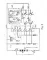
- Figure 2 shows the electronic circuit used in the housing of the edge sensing device.
Ein hohler Schaft mit einem genau geschliffenen Aufnahmebereich 1a zum Einspannen in die Werkzeugspindel einer Maschine ist an seinem unteren Ende mit einem Tastkopf 2 zum Anfahren an Körperkanten und Bezugsflächen ausgerüstet. Der Tastkopf 2 ist elektrisch gegen den Schaft 1 isoliert und weist einen Taster 2a, 2b aus einem absatzartigen Bund 2a und einer stiftförmigen Fortsetzung 2b zum Eintasten in Öffnungen auf.A hollow shaft with a precisely ground receiving area 1a for clamping in the tool spindle of a machine is equipped at its lower end with a
Der Schaft 1 durchsetzt ein Gehäuse 3 aus Kunststoff, in welchem Batterien angeordnet sind. Die obere Stirnseite des Gehäuses 3 zeigt die beiden Leuchtdioden 4 und 5. Das Bodenteil 6 aus Kunststoff ist zum Wechseln der Batterien abschraubbar gestaltet. Mit 7 ist in Figur 1 der Schalter zum Ein- und Ausschalten des Gerätes bezeichnet.The
Mit dem Tastkopf 2 wird das Werkstück 8 (Figur 2) angefahren, nachdem zuvor über den Schalter S1 (Figur 2) mit zwei Schaltbrücken das Gerät eingeschaltet wurde, d.h. eine Betriebsspannung der Batteriezellen 9 angelegt wurde. Ober das Maschinenfutter gelangt eine positive Spannung an das Werkstück.The workpiece 8 (FIG. 2) is approached with the
Die Verstärker V1 bis V4 sind zu einem integrierten Schaltkreis zusammengefaßt, sie erhalten dieselbe Betriebsspannung. Die Zusammenfassung ist durch die Umrandung in unterbrochener Strichführung deutlich gemacht.The amplifiers V1 to V4 are combined to form an integrated circuit, they receive the same operating voltage. The summary is made clear by the outline in broken lines.
Die Verstärker V1 - V4 sind als Komparatoren ausgebildet. Sie reagieren auf definierte Referenzspannungen, d.h. nach dem überschreiten der jeweiligen Referenzspannung schaltet ein Verstärker um.The amplifiers V1-V4 are designed as comparators. They react to defined reference voltages, i.e. After the respective reference voltage has been exceeded, an amplifier switches over.
Berührt der sich drehende Tastkopf 2 mit seinem Taster 2a bzw. 2b das Werkstück 8, so bekommt zunächst der Verstärker V1 Spannungsimpulse. Die Impulse werden über die jeweiligen Impulsbreiten voll verstärkt und zwar über die Betriebsspannung, die zerhackt und dem Kondensator C1 zugeführt wird. Hier wird je nach Impulsbreite eine hohe oder niedrige Gleichspannung erzeugt, die an den positiven Eingängen der Verstärker V2, V3 und V4 anliegt. Die negativen Eingänge dieser Verstärker liegen an den definierten Referenzspannungen, entsprechend den unterschiedlichen Spannungsabfällen an den Widerständen R4 - R7. Überschreitet die Spannung des jeweiligen positiven Eingangs 5,10,12 den Anteil des negativen Eingangs 6, 9, 13, d.h. die jeweilige Referenzspannung, dann schalten die als Komparatoren geschalteten Verstärker um. Zunächst spricht der Verstärker V4 an, es folgt derVerstärker V3, da dessen Referenzspannung höher ist. Bei weiterer Erhöhung der positiven Eingangsspannung durch weiteres Aufladen des Kondensators C1 folgt schließlich der Verstärker V2. Die Verstärker geben die Betriebsspannung in der vorgenannten Reihenfolge weiter an die Transistoren T2 bzw.T1 und an eine Multivibratorschaltung 10.If the rotating
Der Verstärker V4 schaltet bei einer Tasterberührung pro Umdrehung entsprechend einem Drehwinkel von ca. 130°. In diesem Moment zündet die grüne Leuchtdiode 4. Bei einer mit der Dauer zunehmenden Tasterberührung, und zwar nach Überschreiten eines Berührungsdrehwinkels von 210°, wird der positive Eingang des Verstärkers V3 so hoch, daß die Referenzspannung überschritten und die Leuchtdiode 5 (rot) zündet. Bei einem Berührungswinkel von ca. 300° schaltet der Verstärker V2 den Multivibrator 10 ein, der dafür sorgt, daß die Dioden 4 und 5 in einem bestimmten Rhythmus über die Transistoren T3 und T4 aus- und eingeschaltet werden und damit Blinksignale erzeugen.The amplifier V4 switches at the touch of a button per revolution corresponding to an angle of rotation of approx. 130 °. At this moment, the
In Abhängigkeit von der Dauer der Werkstückberührung des Tasters pro Umdrehung wird also der Kondensator C1 mehr oder weniger aufgeladen, so daß die positiven Eingänge für die Verstärker V4, V3 und V2 mehr oder weniger hoch sind und entsprechend die Referenzspannung überschreiten.Depending on the duration of the workpiece contact of the button per revolution, the capacitor C1 is charged to a greater or lesser extent, so that the positive inputs for the amplifiers V4, V3 and V2 are more or less high and accordingly exceed the reference voltage.
Wesentlich bei der vorliegenden Vorrichtung ist, daß die durch Toleranzen bestimmten Abweichungen des Tastkopfes, beispielsweise von der Vertikalen, impulsartige Berührungen beim Anfahren an eine Werkstückkante oder einer Bezugsfläche erzeugen. Diese Abweichungen werden also für die Berührungsanzeigen ausgenutzt. Je geringer die Abweichungen von der theoretisch genauen Lage sind, desto geringer wird die Zeitdifferenz zwischen dem aufeinanderfolgenden Einschalten der Leuchtdioden und dem Übergang zum Blinkrhythmus.It is essential in the present device that the deviations of the probe, for example from the vertical, determined by tolerances, produce impulse-like touches when approaching a workpiece edge or a reference surface. These deviations are therefore used for the touch displays. The smaller the deviations from the theoretically exact position, the smaller the time difference between the successive switching on of the LEDs and the transition to the blinking rhythm.
Es kann somit unabhängig von dem Grad der Abweichungen von der gewünschten theoretisch genauen Lage jede Maschinenspindel mit Hilfe des erfindungsgemäßen Gerätes ausgerichtet werden. Bei einer Werkzeugmaschine mit einer Abweichung null der Maschinenspindel von der gewünschten Ausrichtung würde die Zeitdifferenz zwischen dem aufeinanderfolgenden Einschalten der Leuchtdioden und dem Übergang zum Blinkrhythmus gegen null gehen. Auf diese Weise sind auch äußerst geringe Abweichungen einer Maschinenspindel von der absolut genauen Lage erfaßbar.Thus, regardless of the degree of deviation from the desired theoretically exact position, each machine spindle can be aligned with the aid of the device according to the invention. In the case of a machine tool with zero deviation of the machine spindle from the desired alignment, the time difference between the successive switching on of the light-emitting diodes and the transition to the blinking rhythm would go to zero. In this way, extremely small deviations of a machine spindle from the absolutely precise position can be detected.
Claims (9)
- An arrangement for precise adjustment of the relative position of a workpiece edge and the axis of the machine tool which holds the workpiece spindle, the adjustment being performed by means of a sensing head which is capable of being connected with the spindle for the tool, and the sensing head having a cylindrical sensor and electrically determining and indicating contact with the workpiece edge, the sensing head rotating during the adjustment procedure and being designed for displacement relative to the workpiece, the arrangement being characterized in that the sensing head (2) is moved beyond the position of contact between the sensor (2a, 2b) and the edge of the workpiece (8) until the measured duration of contact per revolution of the rotating sensor (2a, 2b) with the workpiece (8) corresponds to a rotational angle (a) greater than 180° but less than 300°.
- 2. An arrangement according to claim 1, characterized in that the sensing head (2) is displaced in relation to the workpiece edge until the measured duration of contact per revolution of the sensor (2a, 2b) corresponds to a rotational angle (a) of 210°.
- 3. An arrangement according to claim 1 or 2, characterized by a housing (3) equipped with a voltage source (9) and an electrical switching arrangement for optical indicating elements, the housing (3) also being provided with a hollow shaft (1) which is connected with a pole of the voltage source, and the hollow shaft (1) having an accurately ground engagement region (1a) at the end thereof adjacent the machine tool in order to permit insertion of the hollow shaft (1) in the tool spindle, the hollow shaft (1) carrying the sensor (2a, 2b), and the sensor (2a, 2b) being connected with the input of a first amplifier (V1) of the electrical switching-arrangement and having a free end which is electrically insulated from the hollow shaft (1).
- 4. An arrangement according to one of the claims 1-3, characterized in that the sensor has a step-like reduction (2b) in cross section to permit sensing in openings.
- 5. An arrangement according to claim 3 or 4, characterized in that two light-emitting diodes (4, 5) are used as optical indicating elements.
- 6. An arrangement according to one or more of the claims 3-5, characterized in that the switching arrangement has amplifiers (V1-V4) which are incorporated in an integrated circuit for a common operating voltage and are connected as comparators, the positive input of a first amplifier (V1) being connected with the sensing head (2), and the negative inputs of the remaining amplifiers (V2-V4) being supplied with different reference voltages while the positive inputs of these amplifiers (V2-V4) are supplied with d.c. voltage pulses generated by the first amplifier (V1) in dependence upon the duration of contact per revolution of the sensor (2a, 2b) with the workpiece (8), the outputs of two amplifiers (V3, V4) each being connected with a light-emitting diode (4, 5) and the output of a further amplifier (V2) being connected with a multivibrator circuit (10), and the light-emitting diodes (4, 5) being arranged to be periodically switched off by the multivibrator circuit (10) via a transistor connection (T3,T4) in dependence upon the magnitude of the d.c. voltage pulses.
- 7. An arrangement according to claim 6, characterized in that the first amplifier (V1) is arranged to directly receive the pulses from the sensing head (2), the sensing head (2) amplifying these pulses and transmitting the same to a condenser (C1).
- 8. An arrangement according to claim 7, characterized in that the d.c. voltage generated by the condenser (C1) is applied to the positive inputs of the amplifiers connected with the light-emitting diodes (4, 5) and the multivibrator circuit (10).
- 9. An arrangement according to one or more of the claims 6-8, characterized in that the reference voltages correspond to different voltage drops of the operating voltage across respective resistors (R4-R7).
Applications Claiming Priority (2)
| Application Number | Priority Date | Filing Date | Title |
|---|---|---|---|
| DE3129590ADE3129590C2 (en) | 1981-07-28 | 1981-07-28 | Device for the precise setting of the relative position between a workpiece edge and the axis of the tool spindle of cutting machine tools |
| DE3129590 | 1981-07-28 |
Publications (2)
| Publication Number | Publication Date |
|---|---|
| EP0097162A1 EP0097162A1 (en) | 1984-01-04 |
| EP0097162B1true EP0097162B1 (en) | 1986-06-11 |
Family
ID=6137836
Family Applications (1)
| Application Number | Title | Priority Date | Filing Date |
|---|---|---|---|
| EP82902347AExpiredEP0097162B1 (en) | 1981-07-28 | 1982-07-22 | Device for precision adjustment of machine tools |
Country Status (11)
| Country | Link |
|---|---|
| US (1) | US4555857A (en) |
| EP (1) | EP0097162B1 (en) |
| JP (1) | JPS58501198A (en) |
| AT (1) | AT391829B (en) |
| BR (1) | BR8208039A (en) |
| CH (1) | CH659610A5 (en) |
| DE (1) | DE3129590C2 (en) |
| GB (1) | GB2123555B (en) |
| NL (1) | NL8220269A (en) |
| SE (1) | SE436400B (en) |
| WO (1) | WO1983000551A1 (en) |
Families Citing this family (6)
| Publication number | Priority date | Publication date | Assignee | Title |
|---|---|---|---|---|
| DE3711721C1 (en)* | 1987-04-07 | 1988-09-01 | Rolf Leidig | Positioning device for machine tools |
| GB9826093D0 (en)* | 1998-11-28 | 1999-01-20 | Limited | Locating arm for a probe on a coordinate positioning machine |
| SG93289A1 (en) | 1999-12-27 | 2002-12-17 | Toda Kogyo Corp | Magnetic recording medium and process for producing the same |
| US6821618B2 (en) | 2000-12-22 | 2004-11-23 | Toda Kogyo Corporation | Magnetic recording medium and process for producing the same |
| US6816137B2 (en)* | 2001-02-15 | 2004-11-09 | Newscanner, Plc | Visual message display device |
| CA2414250A1 (en) | 2001-12-21 | 2003-06-21 | Magna International Inc. | Electronic measuring device |
Family Cites Families (18)
| Publication number | Priority date | Publication date | Assignee | Title |
|---|---|---|---|---|
| DE224777C (en)* | ||||
| DE664215C (en)* | 1934-12-30 | 1938-08-23 | Vomag Betr S A G | Measuring and centering device for drilling machines, especially for fine boring mills |
| US2109976A (en)* | 1936-11-23 | 1938-03-01 | Jr Winslow S Pierce | Center finding device |
| DE905810C (en)* | 1941-11-30 | 1954-03-08 | Erna Lindner Geb Pfeiffer | Alignment mandrel that is used in the work spindle of a machine tool, in particular a coordinate drilling machine |
| US2451904A (en)* | 1946-07-15 | 1948-10-19 | Aero Supply Mfg Co Inc | Locating tool |
| FR1233695A (en)* | 1959-05-06 | 1960-10-12 | Electronique Et D Automatique | Centering method on machine tools and device for implementing this method |
| GB1076253A (en)* | 1962-12-19 | 1967-07-19 | Rank Organisation Ltd | Method and apparatus for assessing the co-ordinates of the centre of a roughly circular form relative to a fixed axis |
| CH413396A (en)* | 1963-08-29 | 1966-05-15 | Delta Ag Schweizerische Praezi | Device for checking the concentricity of workpieces |
| US3259989A (en)* | 1964-12-21 | 1966-07-12 | Bendix Corp | Method and apparatus for automatic centering system |
| US3370356A (en)* | 1965-08-30 | 1968-02-27 | Henry W.G. Jend | Edge finding tool for machinists |
| DE1477864A1 (en)* | 1965-11-06 | 1969-04-03 | Suhl Feinmesszeugfab Veb | Centering device with circumferential feeler finger |
| GB1177322A (en)* | 1968-01-04 | 1970-01-07 | Electro Discharge Machining Co | Improvements in or relating to Wobblers |
| DE1962877C3 (en)* | 1969-12-16 | 1974-11-14 | Skf Kugellagerfabriken Gmbh, 8720 Schweinfurt | Device for centering a body of revolution |
| DE2210713A1 (en)* | 1972-03-06 | 1973-09-13 | Siemens Ag | ARRANGEMENT FOR POSITIONING A TOOL |
| JPS5087354A (en)* | 1973-12-04 | 1975-07-14 | ||
| JPS6022721B2 (en)* | 1978-07-06 | 1985-06-04 | 豊田工機株式会社 | Centering measurement device using contact detection head |
| GB2039050B (en)* | 1979-01-04 | 1982-12-15 | Rank Organisation Ltd | Measuring centre of curvature |
| US4386344A (en)* | 1981-04-16 | 1983-05-31 | Vecchiatto Charles L | Electronic edge and center locator and method of using same |
- 1981
- 1981-07-28DEDE3129590Apatent/DE3129590C2/ennot_activeExpired
- 1982
- 1982-07-22CHCH1717/83Apatent/CH659610A5/ennot_activeIP Right Cessation
- 1982-07-22EPEP82902347Apatent/EP0097162B1/ennot_activeExpired
- 1982-07-22NLNL8220269Apatent/NL8220269A/enunknown
- 1982-07-22BRBR8208039Apatent/BR8208039A/enunknown
- 1982-07-22USUS06/483,953patent/US4555857A/ennot_activeExpired - Fee Related
- 1982-07-22WOPCT/DE1982/000153patent/WO1983000551A1/enactiveIP Right Grant
- 1982-07-22GBGB08323204Apatent/GB2123555B/ennot_activeExpired
- 1982-07-22JPJP57502415Apatent/JPS58501198A/enactiveGranted
- 1982-07-22ATAT0906582Apatent/AT391829B/ennot_activeIP Right Cessation
- 1983
- 1983-08-26SESE8304639Apatent/SE436400B/ennot_activeIP Right Cessation
Also Published As
| Publication number | Publication date |
|---|---|
| ATA906582A (en) | 1990-06-15 |
| NL8220269A (en) | 1983-11-01 |
| DE3129590C2 (en) | 1984-02-09 |
| SE436400B (en) | 1984-12-10 |
| GB2123555A (en) | 1984-02-01 |
| US4555857A (en) | 1985-12-03 |
| GB8323204D0 (en) | 1983-09-28 |
| JPS58501198A (en) | 1983-07-21 |
| CH659610A5 (en) | 1987-02-13 |
| BR8208039A (en) | 1983-11-22 |
| GB2123555B (en) | 1985-08-29 |
| SE8304639D0 (en) | 1983-08-26 |
| SE8304639L (en) | 1983-08-26 |
| EP0097162A1 (en) | 1984-01-04 |
| DE3129590A1 (en) | 1983-02-10 |
| AT391829B (en) | 1990-12-10 |
| WO1983000551A1 (en) | 1983-02-17 |
| JPH0334561B2 (en) | 1991-05-23 |
Similar Documents
| Publication | Publication Date | Title |
|---|---|---|
| EP0304881B1 (en) | Touch system for coordinate measuring apparatus | |
| EP0332575B1 (en) | Feeler for producing measured value by touching a work piece | |
| DE2422940B2 (en) | DEVICE FOR CONTROLLING THE INFEED MOVEMENT OF A ROTATING TOOL CARRIED BY A TOOL SPINDLE, IN PARTICULAR A GRINDING WHEEL | |
| EP0006160B1 (en) | Device for the reproduceable attachment of two mechanical elements | |
| DE2406170C2 (en) | Measurement control and monitoring device for a centerless cylindrical grinding machine | |
| DE69000140T2 (en) | GRINDING PROCESS WITH MEASUREMENT OF A SHAPED GRINDING WHEEL AND MACHINE TO CARRY OUT IT. | |
| EP1554080A1 (en) | Tool holding device and method for positioning a tool | |
| DE2718903A1 (en) | METHOD FOR ELECTROEROSIVE SPARK MACHINING AND DEVICE FOR CARRYING OUT THE METHOD | |
| EP0106186B1 (en) | Hand tool machine, especially a drilling machine | |
| EP0097162B1 (en) | Device for precision adjustment of machine tools | |
| DE2357837C2 (en) | Measuring device | |
| WO1987007011A1 (en) | Process for measuring the distance between a machine-tool and a workpiece | |
| DE102015224441A1 (en) | Method for relative positioning of a workpiece and a tool in a machine | |
| EP0203370B1 (en) | Screwing device with motor-driven screw driver | |
| DE2518503C2 (en) | ||
| DE3836636C2 (en) | ||
| EP3621769B1 (en) | Grinding and/or eroding machine, and method for measuring and/or referencing the machine | |
| DE4236526C2 (en) | Process for welding welding studs to a workpiece | |
| EP3338945A1 (en) | Dental milling machine with a milling spindle | |
| DE19531484A1 (en) | Arrangement for adjusting angular position of hand tools | |
| EP0224840B1 (en) | Electrical-optical distance measuring instrument | |
| DE2715644A1 (en) | Maintaining consumable welding electrode wire in middle of seam - with electronic appts. having servomotor to move arc welding burner sideways | |
| DE2425209C2 (en) | Process for controlling and monitoring the infeed and grinding process of workpieces | |
| CH620066A5 (en) | Device for motor speed setting on a hand machine tool with a built-in electric motor | |
| DE1513450C (en) | Scanning device for the tracking control of the copying tool of processing machines according to a given line |
Legal Events
| Date | Code | Title | Description |
|---|---|---|---|
| PUAI | Public reference made under article 153(3) epc to a published international application that has entered the european phase | Free format text:ORIGINAL CODE: 0009012 | |
| 17P | Request for examination filed | Effective date:19830812 | |
| AK | Designated contracting states | Designated state(s):BE FR | |
| EL | Fr: translation of claims filed | ||
| GRAA | (expected) grant | Free format text:ORIGINAL CODE: 0009210 | |
| AK | Designated contracting states | Kind code of ref document:B1 Designated state(s):BE FR | |
| ET | Fr: translation filed | ||
| PLBE | No opposition filed within time limit | Free format text:ORIGINAL CODE: 0009261 | |
| STAA | Information on the status of an ep patent application or granted ep patent | Free format text:STATUS: NO OPPOSITION FILED WITHIN TIME LIMIT | |
| 26N | No opposition filed | ||
| PGFP | Annual fee paid to national office [announced via postgrant information from national office to epo] | Ref country code:BE Payment date:19900731 Year of fee payment:9 | |
| PGFP | Annual fee paid to national office [announced via postgrant information from national office to epo] | Ref country code:FR Payment date:19910425 Year of fee payment:10 | |
| PG25 | Lapsed in a contracting state [announced via postgrant information from national office to epo] | Ref country code:BE Effective date:19910731 | |
| BERE | Be: lapsed | Owner name:WESOLY HEINER Effective date:19910731 Owner name:CHRISTOFFEL REINHOLD Effective date:19910731 | |
| PG25 | Lapsed in a contracting state [announced via postgrant information from national office to epo] | Ref country code:FR Effective date:19930331 | |
| REG | Reference to a national code | Ref country code:FR Ref legal event code:ST |