EP0096135A1 - Hinge and clamping device used as a framework angle for tents or caravan awnings - Google Patents
Hinge and clamping device used as a framework angle for tents or caravan awningsDownload PDFInfo
- Publication number
- EP0096135A1 EP0096135A1EP82401057AEP82401057AEP0096135A1EP 0096135 A1EP0096135 A1EP 0096135A1EP 82401057 AEP82401057 AEP 82401057AEP 82401057 AEP82401057 AEP 82401057AEP 0096135 A1EP0096135 A1EP 0096135A1
- Authority
- EP
- European Patent Office
- Prior art keywords
- tube
- hinge
- tents
- clamping device
- device used
- Prior art date
- Legal status (The legal status is an assumption and is not a legal conclusion. Google has not performed a legal analysis and makes no representation as to the accuracy of the status listed.)
- Withdrawn
Links
- 230000000903blocking effectEffects0.000description1
Images
Classifications
- E—FIXED CONSTRUCTIONS
- E04—BUILDING
- E04H—BUILDINGS OR LIKE STRUCTURES FOR PARTICULAR PURPOSES; SWIMMING OR SPLASH BATHS OR POOLS; MASTS; FENCING; TENTS OR CANOPIES, IN GENERAL
- E04H15/00—Tents or canopies, in general
- E04H15/02—Tents combined or specially associated with other devices
- E04H15/06—Tents at least partially supported by vehicles
- E—FIXED CONSTRUCTIONS
- E04—BUILDING
- E04H—BUILDINGS OR LIKE STRUCTURES FOR PARTICULAR PURPOSES; SWIMMING OR SPLASH BATHS OR POOLS; MASTS; FENCING; TENTS OR CANOPIES, IN GENERAL
- E04H15/00—Tents or canopies, in general
- E04H15/32—Parts, components, construction details, accessories, interior equipment, specially adapted for tents, e.g. guy-line equipment, skirts, thresholds
- E04H15/34—Supporting means, e.g. frames
- E04H15/44—Supporting means, e.g. frames collapsible, e.g. breakdown type
- E04H15/46—Supporting means, e.g. frames collapsible, e.g. breakdown type telescoping and foldable
Definitions
- the present inventionrelates to an articulated part making it possible to obtain the desired angles on which there is a locking system.
- the awning corner piecesare welded, which results in a large quantity of different pieces.
- the present inventionrelates to an articulation device making it possible to obtain all the desired angles.
- This devicecomprises a tube on which is welded an articulation bridge where a second tube is riveted and a nut which can receive a clamping screw allowing the blocking, which ensures good stability for the assembly.
Landscapes
- Engineering & Computer Science (AREA)
- Architecture (AREA)
- Civil Engineering (AREA)
- Structural Engineering (AREA)
- Building Awnings And Sunshades (AREA)
- Tents Or Canopies (AREA)
Abstract
Description
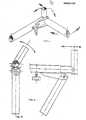
Translated fromFrenchLa présente invention concerne une pièce articulée permettant d' obtenir les angles désirés sur laquelle se trouve un système de bloquage.The present invention relates to an articulated part making it possible to obtain the desired angles on which there is a locking system.
En général, les pièces d'angle d'auvent sont soudées, ce qui occasionne une quantité importante de pièces différentes.In general, the awning corner pieces are welded, which results in a large quantity of different pieces.
C'est pourquoi, la présente invention a pour objet un dispositif d'articulation permettant d'obtenir tous les angles désirés. Ce dispositif comprend un tube sur lequel est soudé un pont d'articulation où l'on vient riveter un 2ème tube et un écrou pouvant recevoir une vis de serrage permettant le bloquage, ce qui assure une bonne stabilité à l'ensemble.This is why, the present invention relates to an articulation device making it possible to obtain all the desired angles. This device comprises a tube on which is welded an articulation bridge where a second tube is riveted and a nut which can receive a clamping screw allowing the blocking, which ensures good stability for the assembly.
Claims (3)
Translated fromFrenchPriority Applications (1)
| Application Number | Priority Date | Filing Date | Title |
|---|---|---|---|
| EP82401057AEP0096135A1 (en) | 1982-06-10 | 1982-06-10 | Hinge and clamping device used as a framework angle for tents or caravan awnings |
Applications Claiming Priority (1)
| Application Number | Priority Date | Filing Date | Title |
|---|---|---|---|
| EP82401057AEP0096135A1 (en) | 1982-06-10 | 1982-06-10 | Hinge and clamping device used as a framework angle for tents or caravan awnings |
Publications (1)
| Publication Number | Publication Date |
|---|---|
| EP0096135A1true EP0096135A1 (en) | 1983-12-21 |
Family
ID=8189915
Family Applications (1)
| Application Number | Title | Priority Date | Filing Date |
|---|---|---|---|
| EP82401057AWithdrawnEP0096135A1 (en) | 1982-06-10 | 1982-06-10 | Hinge and clamping device used as a framework angle for tents or caravan awnings |
Country Status (1)
| Country | Link |
|---|---|
| EP (1) | EP0096135A1 (en) |
Cited By (1)
| Publication number | Priority date | Publication date | Assignee | Title |
|---|---|---|---|---|
| KR101471801B1 (en)* | 2009-08-21 | 2014-12-10 | 애플 인크. | Methods and apparatus for capacitive sensing |
Citations (5)
| Publication number | Priority date | Publication date | Assignee | Title |
|---|---|---|---|---|
| US1347107A (en)* | 1920-04-09 | 1920-07-20 | Joseph L Mccann | Collapsible tent-frame |
| US1407135A (en)* | 1920-07-22 | 1922-02-21 | Vernon M Ebbs | Tent pole |
| DE1557390B1 (en)* | 1965-10-23 | 1970-09-03 | Kirkham Arthur J | Camping wall tent |
| FR2246416A1 (en)* | 1973-10-03 | 1975-05-02 | Pollux Sarl | Support pillar for caravan extension canopy - telescopic tube traps canopy edge in gutter and hooks under bodywork |
| DE2709718A1 (en)* | 1977-03-05 | 1978-09-07 | Johannes Glossmann | Caravan awning tent reinforcing and insulating fittings - include supports, beams, roof rafters, lattice work, and foamed plastic panels |
- 1982
- 1982-06-10EPEP82401057Apatent/EP0096135A1/ennot_activeWithdrawn
Patent Citations (5)
| Publication number | Priority date | Publication date | Assignee | Title |
|---|---|---|---|---|
| US1347107A (en)* | 1920-04-09 | 1920-07-20 | Joseph L Mccann | Collapsible tent-frame |
| US1407135A (en)* | 1920-07-22 | 1922-02-21 | Vernon M Ebbs | Tent pole |
| DE1557390B1 (en)* | 1965-10-23 | 1970-09-03 | Kirkham Arthur J | Camping wall tent |
| FR2246416A1 (en)* | 1973-10-03 | 1975-05-02 | Pollux Sarl | Support pillar for caravan extension canopy - telescopic tube traps canopy edge in gutter and hooks under bodywork |
| DE2709718A1 (en)* | 1977-03-05 | 1978-09-07 | Johannes Glossmann | Caravan awning tent reinforcing and insulating fittings - include supports, beams, roof rafters, lattice work, and foamed plastic panels |
Cited By (1)
| Publication number | Priority date | Publication date | Assignee | Title |
|---|---|---|---|---|
| KR101471801B1 (en)* | 2009-08-21 | 2014-12-10 | 애플 인크. | Methods and apparatus for capacitive sensing |
Similar Documents
| Publication | Publication Date | Title |
|---|---|---|
| US5700102A (en) | Shelter frame connector system | |
| CA2128316C (en) | Support post | |
| EP0909855A3 (en) | Loader vehicle | |
| EP0119114A2 (en) | Device for creating double claddings or curtain walls, and supporting parts, supports and pincers for using this device | |
| US5473790A (en) | Collapsible dust pan | |
| FR2481346A1 (en) | ELEMENTS, OR MADE SHEETS, ROOF COVER, AND ROOF USING THE SAME | |
| EP0162922A1 (en) | Rigid diagonal deployable lattice column | |
| FR2778028A1 (en) | REFLECTOR AND REFLECTOR ELEMENT FOR SPATIAL APPLICATION ANTENNAS AND A METHOD FOR DEPLOYING A REFLECTOR | |
| EP0096135A1 (en) | Hinge and clamping device used as a framework angle for tents or caravan awnings | |
| GB1601400A (en) | Tent frame structure | |
| FR2636598A1 (en) | ARTICULATED PANEL WITH AUTOMATIC LOCKING IN DEPLOYED POSITION, IN PARTICULAR FOR ARTIFICIAL SATELLITE GENERATOR | |
| US4833750A (en) | Ramp section for collapsible floating bridge or ferry | |
| GB2097031A (en) | A tent frame | |
| US5820093A (en) | Universal utility mount for moving vehicle | |
| FR2666612A1 (en) | Dismountable structure for halls, marquees or the like | |
| DE3817070A1 (en) | COMBINABLE WARNING TRIANGLE | |
| AU613901B2 (en) | Coupling unit for composing tubular support structures for lighting assemblies | |
| US3063200A (en) | Horse trailer roof structure | |
| DE3735089C2 (en) | ||
| DE2824771C2 (en) | ||
| EP0346236B1 (en) | Roofing made of a flexible material | |
| EP0894663A3 (en) | Mounting arrangement of a lighting unit for vehicle | |
| BE1005566A3 (en) | Device for connecting elements in tent-shaped constructions, and tent-shapedconstruction | |
| FR2774515A1 (en) | Aerial mounting bracket for use on pylon or building with inclined surface | |
| FR2788802A1 (en) | Formwork assembly for cantilever bridge apron has triangular structures each with two beams forming dihedron with angular opening rapidly set and locked with leg |
Legal Events
| Date | Code | Title | Description |
|---|---|---|---|
| PUAI | Public reference made under article 153(3) epc to a published international application that has entered the european phase | Free format text:ORIGINAL CODE: 0009012 | |
| 17P | Request for examination filed | Effective date:19830502 | |
| AK | Designated contracting states | Designated state(s):AT BE CH DE FR GB IT LI LU NL SE | |
| RAP1 | Party data changed (applicant data changed or rights of an application transferred) | Owner name:SOCIETE JEAN PERRIN | |
| STAA | Information on the status of an ep patent application or granted ep patent | Free format text:STATUS: THE APPLICATION IS DEEMED TO BE WITHDRAWN | |
| 18D | Application deemed to be withdrawn | Effective date:19851001 | |
| RIN1 | Information on inventor provided before grant (corrected) | Inventor name:FLEURY, MICHEL |