EP0093816A1 - Programme apparatus with a combustion-air damper for operating boiler burners - Google Patents
Programme apparatus with a combustion-air damper for operating boiler burnersDownload PDFInfo
- Publication number
- EP0093816A1 EP0093816A1EP82400852AEP82400852AEP0093816A1EP 0093816 A1EP0093816 A1EP 0093816A1EP 82400852 AEP82400852 AEP 82400852AEP 82400852 AEP82400852 AEP 82400852AEP 0093816 A1EP0093816 A1EP 0093816A1
- Authority
- EP
- European Patent Office
- Prior art keywords
- disc
- orifice
- burner
- phase
- air
- Prior art date
- Legal status (The legal status is an assumption and is not a legal conclusion. Google has not performed a legal analysis and makes no representation as to the accuracy of the status listed.)
- Granted
Links
- 238000002485combustion reactionMethods0.000claimsabstractdescription11
- 239000000446fuelSubstances0.000claimsdescription21
- 239000006200vaporizerSubstances0.000claimsdescription12
- 238000001595flow curveMethods0.000claimsdescription7
- 210000000056organAnatomy0.000claimsdescription5
- 239000007800oxidant agentSubstances0.000claimsdescription3
- 230000001360synchronised effectEffects0.000claimsdescription3
- 238000009834vaporizationMethods0.000claimsdescription3
- 230000008016vaporizationEffects0.000claimsdescription3
- 239000012528membraneSubstances0.000claimsdescription2
- 238000007789sealingMethods0.000claims2
- 230000001276controlling effectEffects0.000description5
- 230000001590oxidative effectEffects0.000description3
- 238000001816coolingMethods0.000description2
- 239000012530fluidSubstances0.000description1
- 239000000295fuel oilSubstances0.000description1
- 239000007788liquidSubstances0.000description1
- 230000004048modificationEffects0.000description1
- 238000012986modificationMethods0.000description1
- 230000001105regulatory effectEffects0.000description1
Images


Classifications
- F—MECHANICAL ENGINEERING; LIGHTING; HEATING; WEAPONS; BLASTING
- F23—COMBUSTION APPARATUS; COMBUSTION PROCESSES
- F23L—SUPPLYING AIR OR NON-COMBUSTIBLE LIQUIDS OR GASES TO COMBUSTION APPARATUS IN GENERAL ; VALVES OR DAMPERS SPECIALLY ADAPTED FOR CONTROLLING AIR SUPPLY OR DRAUGHT IN COMBUSTION APPARATUS; INDUCING DRAUGHT IN COMBUSTION APPARATUS; TOPS FOR CHIMNEYS OR VENTILATING SHAFTS; TERMINALS FOR FLUES
- F23L13/00—Construction of valves or dampers for controlling air supply or draught
- F23L13/06—Construction of valves or dampers for controlling air supply or draught slidable only
- F—MECHANICAL ENGINEERING; LIGHTING; HEATING; WEAPONS; BLASTING
- F23—COMBUSTION APPARATUS; COMBUSTION PROCESSES
- F23C—METHODS OR APPARATUS FOR COMBUSTION USING FLUID FUEL OR SOLID FUEL SUSPENDED IN A CARRIER GAS OR AIR
- F23C7/00—Combustion apparatus characterised by arrangements for air supply
- F23C7/008—Flow control devices
- F—MECHANICAL ENGINEERING; LIGHTING; HEATING; WEAPONS; BLASTING
- F23—COMBUSTION APPARATUS; COMBUSTION PROCESSES
- F23N—REGULATING OR CONTROLLING COMBUSTION
- F23N3/00—Regulating air supply or draught
- F23N3/08—Regulating air supply or draught by power-assisted systems
- F23N3/085—Regulating air supply or draught by power-assisted systems using electrical or electromechanical means
Definitions
- the inventionrelates to an operating programmer, with combustion air register, for a boiler burner and more particularly but not exclusively for a vaporization burner.
- Any start of combustion in a burnerrequires an ignition sequence which controls various organs, such as: fuel inlet means (fuel) and air inlet means (oxidant), means of flame and a flame control device.
- One of the objects of the inventionis to provide a programmer, with air register, which allows such an air supply and which also makes it possible to control the various organs of the burner in perfect synchronism with said air supply.
- the programmer according to the inventionis remarkable in that it comprises a profiled disc mounted to rotate in front of the orifice of the conduit. supplying the burner with combustion air to more or less seal said orifice according to the needs of the burner in its different operating phases, as well as a means for driving the disc in rotation and means for controlling said driving means and various burner members, which are actuated by the disc itself, so that said members are controlled precisely as a function of the position of the disc relative to said orifice.
- control meanscomprise microswitches, in a fixed position relative to the supply orifice, which are actuated by tracks arranged on the disc while the drive means of the disc is advantageously a synchronous electric motor of such so that the angular speed of rotation of the disc is constant.
- the inventionrelates of course to all burners with fluid or even pulverulent fuel but it is more particularly intended for burners with liquid fuel and more particularly still for burners provided with a vaporizer in which said fuel is conveyed by air. that the burner described in French patent n ° 2429967 in the name of the same applicant and which is provided with a vaporization duct or channel.
- a particular embodiment according to the inventionis remarkable in that an orifice is provided in the vicinity of the orifice for supplying combustion air, for supplying said vaporizer, its position being such that the disc does not '' opens only between phases (b) and (c) to close it completely after phase (e) so as to ensure a pre-sweep of the vaporizer before ignition and a post-sweep of the vaporizer after the shutdown of said burner .
- Numerous meansare also provided for controlling the burner members such as the aforementioned tracks arranged on the disc, in the form for example of raised tracks or ribs intended to urge microswitches, the shape and position of the ribs being studied to obtain actuations at specific times.
- the programmer according to the invention shown in Figure 1comprises a cylindrical housing formed by two housings 1 and 2 fixed to each other.
- the casing 1is provided with an orifice 3 intended to be connected to an air intake powered by a turbine and the casing 2 is provided with two orifices 4 and 5.
- the orifice 4is formed opposite the orifice 3 and it is intended to be connected to the combustion air supply duct of the burner while the orifice 5 is shown by way of example and is only useful for a burner provided with a vaporizer, the invention being able to naturally be applied to other types of burners.
- the disc 6is provided in this example with two tracks in the form of ribs 9 and 10 projecting towards the casing 1 and which are intended to urge two microswitches 11 and 12 respectively fixed on the casing 1.
- the two ribs 9 and 10 of unequal lengthsare concentric and form arcs of a circle while in this example the microswitches are arranged substantially on the same radius.
- FIG. 1clearly shows the microswitches 11 and 12, the connection terminals of which appear on the outside face of the casing 1, but it is clear that these, provided for example with small rollers, protrude inwards so that they can be acted upon by the corresponding ribs 9 and 10.
- the references 11 and 12 of FIGS. 2 to 8of course only represent the position of the microswitches.
- FIG. 1also shows a microswitch 13 intended to be actuated by a membrane 14 thus forming a pressure switch for controlling the air pressure.
- the discIn the initial rest position when the burner is stopped, the disc is in the position shown in FIG. 3 in which it closes the orifices 4 and 5, the microswitch 11 being biased by the small rib 9.
- the air turbineWhen there is a start command, for example by the aquastat of the boiler which is lacking in temperature, the air turbine is energized at the same time as the motor 8 driving the disc 6 which starts in this example turn clockwise at a constant speed of around 2 revolutions per minute.
- Figure 4shows the disc 6 in an intermediate position in which it always closes the orifice 5 thus avoiding any cooling of the vaporizer but completely discovers the orifice 4 thanks to an appropriate notch thus ensuring a pre-scanning of a few seconds, the disc continuing its rotation.
- the discreaches the position shown in FIG. 5 in which it has just discovered the orifice 5 by the aforementioned notch thus ensuring a pre-scanning of the vaporizer while it partially closes the orifice 4 so as to reduce the air flow to the burner.
- the microswitch 12is biased by the start of the rib 10. This bias simultaneously controls, by appropriate relays, the starting of the ignition means of the burner such as fuel supply means, ignition means . , device for checking the presence of flame.
- the fuel supply meansare for example a fuel pump and a solenoid valve
- the ignition meansinclude an electrode energized by an ignition transformer and the flame control device is an ionization control device.
- the sector of the disc, referenced in this figure by 15, which will pass in front of the orifice 4,has a particular shape in order to obtain an air flow curve most suitable for starting and which is a function as already mentioned of the fuel supply flow curve.
- sector 15is defined by a arc of a circle whose geometric center is located in. the fourth quadrant of the casing 2 according to FIGS. 2 to 8, substantially on the bisector of this quadrant.
- the microswitch 12is released by the rib 10 and the disc 6 stops in this operating position where the orifice 4 is wide open. It should also be noted that relays are provided so that, on the one hand, the flame control device stops the ignition means as soon as a flame is detected, even if the microswitch 12 is still stressed by the rib 10 and on the other hand, the arrival of the fuel can not continue after the release of the microswitch 12 if the flame control device detects the presence of a flame, thus ensuring good security.
- the aquastatcontrols the stopping of the fuel supply means and the restarting of the drive motor 8.
- the discthen passes into the intermediate position shown in FIG. 8 where it closes the orifice 5 and finally the disc comes back to its initial position in FIG. 3 in which the microswitch 11 is biased by the rib 9 controlling the stop of the disc and the end of the cycle.
- the disccompletely closes the orifice 4 and thus constitutes a draft cut avoiding any unnecessary cooling of the burner and of the boiler hearth.
Landscapes
- Engineering & Computer Science (AREA)
- Chemical & Material Sciences (AREA)
- Combustion & Propulsion (AREA)
- Mechanical Engineering (AREA)
- General Engineering & Computer Science (AREA)
- Regulation And Control Of Combustion (AREA)
- Air Supply (AREA)
Abstract
Description
Translated fromFrenchL'invention concerne un programmateur de fonctionnement, à registre d'air comburant, pour brûleur de chaudière et plus particulièrement mais non exclusivement pour brûleur à vaporisation.The invention relates to an operating programmer, with combustion air register, for a boiler burner and more particularly but not exclusively for a vaporization burner.
Tout démarrage de combustion dans un brûleur nécessite une séquence d'allumage qui commande au moment voulu divers organes tels que : des moyens d'arrivée du combustible (carburant) et des moyens d'arrivée d'air (comburant), des moyens d'inflamation et un dispositif de contrôle de flamme.Any start of combustion in a burner requires an ignition sequence which controls various organs, such as: fuel inlet means (fuel) and air inlet means (oxidant), means of flame and a flame control device.
Il existe bien sûr divers dispositifs de commande et de contrôle des phases constituant la séquence d'allumage, mais généralement les dispositifs connus assurent uniquement la mise en fonction des organes sans permettre une synchronisation des débits du carburant et du comburant.There are of course various command and control devices for the phases constituting the ignition sequence, but generally the known devices only ensure that the members are put into operation without allowing synchronization of the flow rates of the fuel and of the oxidant.
Or il est clair que le débit instantanné du combustible au démarrage ne représente pas 100 % du débit en régime permanent. Une bonne combustion (rendement, encrassement évité etc...) nécessite donc une alimentation en air comburant régulée au moment du démarrage de manière à fournir un débit d'air optimisé en fonction du débit du combustible, les courbes de débit pouvant être homothétiques l'une de l'autre ou au contraire assurer un démarrage en manque ou excès d'air.Now it is clear that the instantaneous flow of fuel at start-up does not represent 100% of the flow in steady state. Good combustion (efficiency, fouling avoided, etc.) therefore requires a supply of oxidizing air that is regulated at the time of start-up so as to provide an optimized air flow according to the fuel flow, the flow curves being able to be homothetic l 'one of the other or on the contrary ensure a start in lack or excess of air.
L'un des buts de l'invention est de fournir un programmateur, à registre d'air, qui permet justement une telle alimentation d'air et qui permet en outre d'assurer la commande des divers organes du brûleur en synchronisme parfait avec ladite alimentation d'air.One of the objects of the invention is to provide a programmer, with air register, which allows such an air supply and which also makes it possible to control the various organs of the burner in perfect synchronism with said air supply.
Pour atteindre ce but le programmateur selon l'invention est remarquable en ce qu'il comporte, un disque profilé monté rotatif devant l'orifice du conduit d'alimentation du brûleur en air comburant pour obturer plus ou moins ledit orifice en fonction des besoins du brûleur dans ses différentes phases de fonctionnement, ainsi qu'un moyen d'entraînement en rotation du disque et des moyens de commande dudit moyen d'entraînement et des divers organes du brûleur, qui sont actionnés par le disque lui-même, de telle sorte que lesdits organes sont commandés de manière précise en fonction de la position du disque par rapport audit orifice.To achieve this goal, the programmer according to the invention is remarkable in that it comprises a profiled disc mounted to rotate in front of the orifice of the conduit. supplying the burner with combustion air to more or less seal said orifice according to the needs of the burner in its different operating phases, as well as a means for driving the disc in rotation and means for controlling said driving means and various burner members, which are actuated by the disc itself, so that said members are controlled precisely as a function of the position of the disc relative to said orifice.
De préférence les moyens de commande comportent des microrupteurs, en position fixe par rapport à l'orifice d'alimentation, qui sont actionnés par des pistes aménagées sur le disque tandis que le moyen d'entraînement du disque est avantageusement un moteur électrique synchrone de telle sorte que la vitesse angulaire de rotation du disque est constante.Preferably the control means comprise microswitches, in a fixed position relative to the supply orifice, which are actuated by tracks arranged on the disc while the drive means of the disc is advantageously a synchronous electric motor of such so that the angular speed of rotation of the disc is constant.
Selon un mode préféré de réalisation de l'invention le contour du disque est tel qu'il réalise successivement, au cours d'un cycle de rotation, les phases suivantes :
- a) Obturation complète de l'orifice d'alimentation en air du brûleur, en position initiale d'arrêt ;
- b) Ouverture complète de l'orifice ;
- c) Obturation partielle de l'orifice ;
- d) Réouverture complète de l'orifice ;
- e) Réobturation complète de l'orifice ;
- f) Retour en position initiale.
- a) Complete plugging of the air supply port of the burner, in the initial stop position;
- b) complete opening of the orifice;
- c) Partial obturation of the orifice;
- d) Complete reopening of the orifice;
- e) Complete plugging of the orifice;
- f) Return to the initial position.
L'arrivée du combustible au démarrage se situe entre les phases (c) et (d) et c'est pourquoi le contour du disque présente entre les zones qui correspondent aux phases précitées, une forme telle que la courbe de débit d'air qu'elle procure soit optimisée en fonction de la courbe de débit dudit combustible, au démarrage.The arrival of the fuel at start-up is situated between phases (c) and (d) and this is why the contour of the disc has, between the zones which correspond to the abovementioned phases, a shape such as the air flow curve which 'it provides is optimized as a function of the flow curve of said fuel, at startup.
L'invention concerne bien sûr tous les brûleurs à combustible fluide ou même pulvérulent mais elle est plus particulièrement destinée aux brûleurs à combustible liquide et plus particulièrement encore aux brûleurs munis d'un vaporisateur dans lequel est véhiculé ledit combustible par de l'air.tel que le brûleur décrit dans le brevet francais n° 2429967 au nom du même demandeur et qui est pourvu d'un conduit ou canal de vaporisation.The invention relates of course to all burners with fluid or even pulverulent fuel but it is more particularly intended for burners with liquid fuel and more particularly still for burners provided with a vaporizer in which said fuel is conveyed by air. that the burner described in French patent n ° 2429967 in the name of the same applicant and which is provided with a vaporization duct or channel.
Dans ce cas, un mode de réalisation particulier selon l'invention est remarquable en ce qu'un orifice est prévu au voisinnage de l'orifice d'alimentation en air comburant, pour alimenter ledit vaporisateur, sa position étant telle que le disque ne l'ouvre qu'entre les phases (b) et (c) pour l'obturer complètement après la phase (e) de manière à assurer un prébalayage du vaporisateur avant l'allumage et un post-balayage du vaporisateur après l'arrêt dudit brûleur.In this case, a particular embodiment according to the invention is remarkable in that an orifice is provided in the vicinity of the orifice for supplying combustion air, for supplying said vaporizer, its position being such that the disc does not '' opens only between phases (b) and (c) to close it completely after phase (e) so as to ensure a pre-sweep of the vaporizer before ignition and a post-sweep of the vaporizer after the shutdown of said burner .
De nombreux moyens sont en outre prévus pour commander les organes du brûleur telles que les pistes susmentionnées aménagées sur le disque, sous forme par exemple de pistes en relief ou nervures destinées à solliciter des microrupteurs, la forme et la position des nervures étant étudiées pour obtenir des actionnements à des moments précis.Numerous means are also provided for controlling the burner members such as the aforementioned tracks arranged on the disc, in the form for example of raised tracks or ribs intended to urge microswitches, the shape and position of the ribs being studied to obtain actuations at specific times.
L'invention sera bien comprise et d'autres caractéristiques apparaîtront à la lecture de la description qui va suivre et qui se réfère aux dessins annéxés dans lesquels :
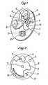
- La figure 1 montre une perspective avec arraché d'un appareil selon l'invention.
- Les figures 2 à 8 montrent le disque rotatif dans sept positions angulaires différentes.
- Figure 1 shows a perspective with cutaway of an apparatus according to the invention.
- Figures 2 to 8 show the rotating disc in seven different angular positions.
Le programmateur selon l'invention représentée à la figure 1 comporte un boitier cylindrique formé de deux carters 1 et 2 fixés l'un à l'autre.The programmer according to the invention shown in Figure 1 comprises a cylindrical housing formed by two
Le carter 1 est pourvu d'un orifice 3 destiné à être relié à une arrivée d'air propulsée par une turbine et le carter 2 est pourvu de deux orifices 4 et 5. L'orifice 4 est ménagé en regard de l'orifice 3 et il est destiné à être branché sur le conduit d'alimentation en air comburant du brûleur tandis que l'orifice 5 est représenté à titre d'exemple et ne trouve son utilité que pour un brûleur muni d'un vaporisateur, l'invention pouvant naturellement être appliquée à d'autres types de brûleurs.The casing 1 is provided with an
Dans l'espace compris entre les carters 1 et 2 est monté un disque 6 qui peut être entraîné en rotation au moyen d'un carré d'entraînement 7 (figure 2) et d'un moteur électrique synchrone et réducteur 8(figure 1). Comme le montre les figures 2 à 8 (sur lesquelles le carter 1 est retiré), le disque 6 présente un contour très particulier pour les raisons qui seront expliquées ci-après.In the space between the
En outre le disque 6 est muni dans cet exemple de deux pistes sous forme de nervures 9 et 10 en saillie vers le carter 1 et qui sont destinées à solliciter deux microrupteurs respectivement 11 et 12 fixés sur le carter 1.In addition, the
Les deux nervures 9 et 10 de longueurs inégales sont concentriques et forment des arcs de cercle tandis que dans cet exemple les microrupteurs sont disposés sensiblement sur un même rayon.The two
La figure 1 montre bien les microrupteurs 11 et 12 dont les bornes de branchement apparaissent sur la face extérieure du carter 1 mais il est clair que ceux-ci, munis par exemple de petites roulettes font saillies vers l'intérieur pour pouvoir être sollicités par les nervures correspondantes 9 et 10. En outre les références 11 et 12 des figures 2 à 8 ne représentent bien sûr que la position des microrupteurs.FIG. 1 clearly shows the
La figure 1 montre encore un microrupteur 13 destiné à être actionné par une membrane 14 formant ainsi un pressostat de contrôle de pression d'air.FIG. 1 also shows a
Dans la position initiale de repos lorsque le brûleur est à l'arrêt, le disque est dans la position représentée à la figure 3 dans laquelle il obture les orifices 4 et 5, le microrupteur 11 étant sollicité par la petite nervure 9.In the initial rest position when the burner is stopped, the disc is in the position shown in FIG. 3 in which it closes the
Lorsqu'il y a une commande de démarrage, par exemple par l'aquastat de la chaudière qui est en manque de température, la turbine à air est mise sous tension en même temps que démarre le moteur 8 d'entraînement du disque 6 qui va tourner dans cet exemple dans le sens des aiguilles d'une montre à une vitesse constante d'environ 2 tours à la minute.When there is a start command, for example by the aquastat of the boiler which is lacking in temperature, the air turbine is energized at the same time as the motor 8 driving the
La figure 4 montre le disque 6 dans une position intermédiaire dans laquelle il obture toujours l'orifice 5 évitant ainsi tout refroidissement du vaporisateur mais découvre complètement l'orifice 4 grâce à une échancrure appropriée assurant ainsi un pré-balayage de quelques secondes, le disque continuant sa rotation.Figure 4 shows the
Le disque parvient à la position représentée à la figure 5 dans laquelle il vient de découvr.ir l'orifice 5 par l'échancrure précitée assurant ainsi un pré- balayage du vaporisateur tandis qu'il obture partiellement l'orifice 4 de façon à réduire le débit d'air au brûleur. A ce moment précis le microrupteur 12 est sollicité par le début de la nervure 10. Cette sollicitation commande simultanément par des relais appropriés la mise en route des moyens d'allumage du brûleur tels que moyens d'alimentation en combustible, moyensd'inflammation, disposi- =if de contrôle de présence de flamme. Pour un brûleur a fuel, les moyens d'alimentation en combustible sont par exemple une pompe à fuel et une électro-vanne, les moyens d'inflamation comportent une électrode mise sous tension par un transformateur d'allumage et le dispositif de contrôle de flamme est un dispositif de contrôle par ionisation.The disc reaches the position shown in FIG. 5 in which it has just discovered the
C'est donc ici, à partir de la figure 5 que se déroule la séquence d'allumage, le disque continuant de tourner jusqu'à prendre la position de la fig.6 . Pendant tout le temps de la rotation du disque qui passe de la figure 5 à la figure 6, le microrupteur 12 est sollicité par la nervure 10 et l'orifice 4 passe d'une obturation partielle (fig.5) à une ouverture complète (fig.6).It is therefore here, from FIG. 5, that the ignition sequence takes place, the disc continuing to rotate until it takes the position of FIG. 6. During the entire time of rotation of the disc which passes from FIG. 5 to FIG. 6, the
Comme le montre la figure 5, le secteur du disque, référencé sur cette figure par 15, qui va passer devant l'orifice 4, présente une forme particulière afin d'obtenir une courbe de débit d'air la mieux appropriée pour le démarrage et qui est fonction comme il a déjà été dit de la courbe de débit d'alimentation en combustible. Dans cet exemple le secteur 15 est défini par un arc de cercle dont le centre géométrique se situe dans . le quatrième quadrant du carter 2 selon les figures 2 à 8, sensiblement sur la bissectrice de ce quadrant.As shown in FIG. 5, the sector of the disc, referenced in this figure by 15, which will pass in front of the
En arrivant à la position de la figure 6, le microrupteur 12 est relaché par la nervure 10 et le disque 6 s'arrête dans cette position de fonctionnement où l'orifice 4 est grand ouvert. Il y a lieu de noter en outre que des relais sont prévus de telle sorte que,d'une part,le dispositif de contrôle de flamme arrête le moyen d'inflammation dès qu'une flamme est détectée, même si le microrupteur 12 est encore sollicité par la nervure 10 et d'autre part,l'arrivée du combustible ne peut se poursuivre après le relachement du microrupteur 12 que si le dispositif de contrôle de flamme détecte bien la présence d'une flamme, assurant ainsi une bonne sécurité.Arriving at the position of Figure 6, the
La sécurité est encore accrue et les fonctions du programmateur augmentées par le pressostat (13,14) qui permet de vérifier la pression et le bon fonctionnement de la turbine, et éventuellement d'arrêter en cas de défaillance au moins certains des organes du brûleur.Safety is further increased and the functions of the programmer increased by the pressure switch (13,14) which makes it possible to check the pressure and the proper functioning of the turbine, and possibly stop in the event of failure of at least some of the burner components.
La position fixe du disque de la figure 6 se maintient pendant toute la durée de fonctionnement du brûleur.The fixed position of the disc in Figure 6 is maintained throughout the operating time of the burner.
Dès que la bonne température est atteinte dans la chaudière, l'aquastat commande l'arrêt des moyens d'alimentation du combustible et la remise en route du moteur d'entrainement 8.As soon as the correct temperature is reached in the boiler, the aquastat controls the stopping of the fuel supply means and the restarting of the drive motor 8.
Le disque reprend sa rotation en passant par la position intermédiaire de la figure 7 dans laquelle il obture complètement l'orifice 4 tout en laissant ou- vers l'orifice 5 permettant ainsi un post-balayage du vaporisateur.The disc resumes its rotation passing through the intermediate position of Figure 7 in which it completely closes the
Le disque passe ensuite dans la position in- temédiaire montrée à la figure 8 où il obture l'orifice 5 et enfin le disque vient reprendre sa position initiale de la figure 3 dans laquelle le microrupteur 11 est sollicité par la nervure 9 commandant l'arrêt du disque et la fin du cycle.The disc then passes into the intermediate position shown in FIG. 8 where it closes the
On peut en outre remarquer que dans cette position qui est maintenue pendant toute la période d'arrêt du brûleur, le disque obture complètement l'orifice 4 et constitue ainsi un coupe tirage évitant tout refroidissement inutile du brûleur et du foyer de la chaudière.It can also be noted that in this position which is maintained throughout the shutdown period of the burner, the disc completely closes the
Les fonctions du programmateur apparaissent maintenant clairement et on peut notamment rappeler
- - Son rôle de temporisateur dû au fait de sa vitesse constante qui crée ainsi une période précise du cycle de fonctionnement.
- - Son rôle de régulateur de débit d'air
- - Son rôle de synchronisateur entre la commande des organes et le débit d'air, dû au fait que le disque qui sert de registre d'air sert aussi de dispositif d'actionnement au moyen des pistes dont il est muni.
- - Son rôle d'obturateur en coupe tirage.
- - Its role as timer due to its constant speed which thus creates a precise period of the operating cycle.
- - Its role as an air flow regulator
- - Its role as a synchronizer between the control of the organs and the air flow, due to the fact that the disc which serves as an air register also serves as an actuating device by means of the tracks with which it is provided.
- - Its role as a shutter in the draft section.
Il est toutefois clair que le mode de réalisation qui vient d'être décrit peut subir de nombreuses modifications sans sortir du cadre de l'invention. Il est notamment possible d'imaginer un nombre quelconque de pistes de commande si l'on désire actionner plus de microrupteurs commandant d'autres fonctions que celles mentionnées. En outre ces pistes peuvent être en creux ou autrement et commander d'autres moyens que des microrupteurs, comme des diodes par exemple pour une commande électronique. De même,le profil donné au disque peut être différent si l'on désire par exemple supprimer la fonction de coupe tirage des figures 8 et 3, avoir un débit d'air maximum au démarrage à la figure 5 etc...It is however clear that the embodiment which has just been described can undergo numerous modifications without departing from the scope of the invention. It is in particular possible to imagine any number of control tracks if it is desired to actuate more microswitches controlling other functions than those mentioned. In addition, these tracks can be hollow or otherwise and control other means than microswitches, such as diodes for example for electronic control. Likewise, the profile given to the disc may be different if it is desired, for example, to suppress the draft cut function in FIGS. 8 and 3, to have a maximum air flow rate at start-up in FIG. 5, etc.
Claims (10)
Translated fromFrenchPriority Applications (3)
| Application Number | Priority Date | Filing Date | Title |
|---|---|---|---|
| AT82400852TATE28505T1 (en) | 1982-05-07 | 1982-05-07 | PROGRAMMING DEVICE, WITH COMBUSTION AIR FLAP, FOR CONTROLLING BOILER BURNERS. |
| EP82400852AEP0093816B1 (en) | 1982-05-07 | 1982-05-07 | Programme apparatus with a combustion-air damper for operating boiler burners |
| DE8282400852TDE3276834D1 (en) | 1982-05-07 | 1982-05-07 | Programme apparatus with a combustion-air damper for operating boiler burners |
Applications Claiming Priority (1)
| Application Number | Priority Date | Filing Date | Title |
|---|---|---|---|
| EP82400852AEP0093816B1 (en) | 1982-05-07 | 1982-05-07 | Programme apparatus with a combustion-air damper for operating boiler burners |
Publications (2)
| Publication Number | Publication Date |
|---|---|
| EP0093816A1true EP0093816A1 (en) | 1983-11-16 |
| EP0093816B1 EP0093816B1 (en) | 1987-07-22 |
Family
ID=8189907
Family Applications (1)
| Application Number | Title | Priority Date | Filing Date |
|---|---|---|---|
| EP82400852AExpiredEP0093816B1 (en) | 1982-05-07 | 1982-05-07 | Programme apparatus with a combustion-air damper for operating boiler burners |
Country Status (3)
| Country | Link |
|---|---|
| EP (1) | EP0093816B1 (en) |
| AT (1) | ATE28505T1 (en) |
| DE (1) | DE3276834D1 (en) |
Cited By (3)
| Publication number | Priority date | Publication date | Assignee | Title |
|---|---|---|---|---|
| GB2306001A (en)* | 1995-10-06 | 1997-04-23 | British Gas Plc | Fuel-fired burners |
| WO2008046425A3 (en)* | 2006-10-19 | 2008-07-17 | Aduro As | A method and device for controlling the supply of combustion air to a combustion chamber |
| CN101162092B (en)* | 2007-11-15 | 2012-10-03 | 林泽村 | Air regulating device for gas stove burner |
Citations (8)
| Publication number | Priority date | Publication date | Assignee | Title |
|---|---|---|---|---|
| US1798431A (en)* | 1929-02-16 | 1931-03-31 | Arthur C Mcwilliams | Thermostatic flue regulator |
| FR793286A (en)* | 1934-08-04 | 1936-01-21 | Diffusion | Thermostatic draft regulator |
| FR1342829A (en)* | 1962-09-06 | 1963-11-15 | Device for automatic titration of boilers | |
| FR1425113A (en)* | 1965-02-22 | 1966-01-14 | Automatic draft regulator | |
| DE2403083A1 (en)* | 1974-01-23 | 1975-07-31 | Ennking Heinz Dr Rer Nat | Continuous oil firing plant operation - in which widths of passage openings of air and fuel ducts are regulated linearly and in common |
| US4089638A (en)* | 1976-07-29 | 1978-05-16 | Trucco Horacio A | Apparatus for gassification, premixing and combustion of liquid fuels |
| DE2932106A1 (en)* | 1979-08-08 | 1981-02-26 | Ferdinand Friess | Central heating plant flue seal and boiler-room ventilator - is plant-thermostat controlled disc stopping either gas-or air-flow into chimney |
| US4295603A (en)* | 1979-11-13 | 1981-10-20 | Emhart Industries, Inc. | Means controlling a flue damper |
- 1982
- 1982-05-07DEDE8282400852Tpatent/DE3276834D1/ennot_activeExpired
- 1982-05-07ATAT82400852Tpatent/ATE28505T1/ennot_activeIP Right Cessation
- 1982-05-07EPEP82400852Apatent/EP0093816B1/ennot_activeExpired
Patent Citations (8)
| Publication number | Priority date | Publication date | Assignee | Title |
|---|---|---|---|---|
| US1798431A (en)* | 1929-02-16 | 1931-03-31 | Arthur C Mcwilliams | Thermostatic flue regulator |
| FR793286A (en)* | 1934-08-04 | 1936-01-21 | Diffusion | Thermostatic draft regulator |
| FR1342829A (en)* | 1962-09-06 | 1963-11-15 | Device for automatic titration of boilers | |
| FR1425113A (en)* | 1965-02-22 | 1966-01-14 | Automatic draft regulator | |
| DE2403083A1 (en)* | 1974-01-23 | 1975-07-31 | Ennking Heinz Dr Rer Nat | Continuous oil firing plant operation - in which widths of passage openings of air and fuel ducts are regulated linearly and in common |
| US4089638A (en)* | 1976-07-29 | 1978-05-16 | Trucco Horacio A | Apparatus for gassification, premixing and combustion of liquid fuels |
| DE2932106A1 (en)* | 1979-08-08 | 1981-02-26 | Ferdinand Friess | Central heating plant flue seal and boiler-room ventilator - is plant-thermostat controlled disc stopping either gas-or air-flow into chimney |
| US4295603A (en)* | 1979-11-13 | 1981-10-20 | Emhart Industries, Inc. | Means controlling a flue damper |
Cited By (5)
| Publication number | Priority date | Publication date | Assignee | Title |
|---|---|---|---|---|
| GB2306001A (en)* | 1995-10-06 | 1997-04-23 | British Gas Plc | Fuel-fired burners |
| US5795144A (en)* | 1995-10-06 | 1998-08-18 | British Gas Plc | Fuel-fired burners |
| GB2306001B (en)* | 1995-10-06 | 1999-09-08 | British Gas Plc | Fuel-fired burners |
| WO2008046425A3 (en)* | 2006-10-19 | 2008-07-17 | Aduro As | A method and device for controlling the supply of combustion air to a combustion chamber |
| CN101162092B (en)* | 2007-11-15 | 2012-10-03 | 林泽村 | Air regulating device for gas stove burner |
Also Published As
| Publication number | Publication date |
|---|---|
| EP0093816B1 (en) | 1987-07-22 |
| ATE28505T1 (en) | 1987-08-15 |
| DE3276834D1 (en) | 1987-08-27 |
Similar Documents
| Publication | Publication Date | Title |
|---|---|---|
| EP0942156B1 (en) | Exhaust heat exchanger device | |
| EP0506516B1 (en) | Combustion air control device for turbomachine combustor | |
| FR2586784A1 (en) | SANITARY MIXING VALVES | |
| FR2919673A1 (en) | ASSISTANCE AND RELIEF FOR THE ELECTRIC DRIVE OF A FUEL PUMP IN A TURBOMOTEUR | |
| EP0093816B1 (en) | Programme apparatus with a combustion-air damper for operating boiler burners | |
| FR2480908A1 (en) | FIREPLACE WITH DRAFT LIMITER AND VENTILATION SYSTEM | |
| FR2664678A1 (en) | Catalytic burner | |
| FR2917156A1 (en) | Methanol- or ethanol burner insert fitted in fireplaces, includes automatically-operated controller with actuator to adjust flame height | |
| EP0656272A1 (en) | Distribution device for a motor vehicle air conditioning installation | |
| KR100320025B1 (en) | Gas saving system for welding brazing soldering | |
| FR2564143A1 (en) | HOT-TYPE SELF-MAIN GAS GENERATOR WITH CONTROL OF OPERATING STEPS | |
| EP0915292A1 (en) | Universal device for mixing two gaseous fluids | |
| EP0064017A1 (en) | Supply apparatus for mobile gas heaters | |
| FR2530786A1 (en) | Heat-activated diffuser for an air-conditioning system. | |
| EP0318380A1 (en) | Modulating gas-feeding mechanism for a burner of an apparatus of the gas boiler kind | |
| CA2029187A1 (en) | Gas heater with catalytic burner and control device | |
| WO1997018416A1 (en) | Cooking appliance with a catalytic burner | |
| FR2561757A1 (en) | Gas water heater without a permanent pilot light | |
| FR2816394A1 (en) | DOMESTIC RADIATION AND CONVECTION HEATING APPARATUS | |
| JPH0960754A (en) | Motor-operated valve device | |
| JPH062941A (en) | Ignition device for hot-water heater | |
| KR850001715Y1 (en) | Flashback Arrestor | |
| FR2576395A1 (en) | Device for burning solid fuels | |
| JPH1182993A (en) | Gas control device | |
| FR2773389A1 (en) | OPERATING PROCESS OF A GAS-MIXED HEAT PRODUCTION APPARATUS, AND APPARATUS FOR IMPLEMENTING THIS PROCESS |
Legal Events
| Date | Code | Title | Description |
|---|---|---|---|
| PUAI | Public reference made under article 153(3) epc to a published international application that has entered the european phase | Free format text:ORIGINAL CODE: 0009012 | |
| AK | Designated contracting states | Designated state(s):AT BE CH DE FR GB IT LI LU NL SE | |
| 17P | Request for examination filed | Effective date:19840514 | |
| 17Q | First examination report despatched | Effective date:19860424 | |
| GRAA | (expected) grant | Free format text:ORIGINAL CODE: 0009210 | |
| AK | Designated contracting states | Kind code of ref document:B1 Designated state(s):AT BE CH DE FR GB IT LI LU NL SE | |
| PG25 | Lapsed in a contracting state [announced via postgrant information from national office to epo] | Ref country code:NL Effective date:19870722 Ref country code:IT Free format text:LAPSE BECAUSE OF FAILURE TO SUBMIT A TRANSLATION OF THE DESCRIPTION OR TO PAY THE FEE WITHIN THE PRESCRIBED TIME-LIMIT;WARNING: LAPSES OF ITALIAN PATENTS WITH EFFECTIVE DATE BEFORE 2007 MAY HAVE OCCURRED AT ANY TIME BEFORE 2007. THE CORRECT EFFECTIVE DATE MAY BE DIFFERENT FROM THE ONE RECORDED. Effective date:19870722 Ref country code:AT Effective date:19870722 | |
| REF | Corresponds to: | Ref document number:28505 Country of ref document:AT Date of ref document:19870815 Kind code of ref document:T | |
| PG25 | Lapsed in a contracting state [announced via postgrant information from national office to epo] | Ref country code:SE Effective date:19870731 | |
| REF | Corresponds to: | Ref document number:3276834 Country of ref document:DE Date of ref document:19870827 | |
| REG | Reference to a national code | Ref country code:FR Ref legal event code:GC | |
| REG | Reference to a national code | Ref country code:FR Ref legal event code:GC | |
| NLV1 | Nl: lapsed or annulled due to failure to fulfill the requirements of art. 29p and 29m of the patents act | ||
| PG25 | Lapsed in a contracting state [announced via postgrant information from national office to epo] | Ref country code:LU Free format text:LAPSE BECAUSE OF NON-PAYMENT OF DUE FEES Effective date:19880531 Ref country code:LI Effective date:19880531 Ref country code:CH Effective date:19880531 | |
| PLBE | No opposition filed within time limit | Free format text:ORIGINAL CODE: 0009261 | |
| STAA | Information on the status of an ep patent application or granted ep patent | Free format text:STATUS: NO OPPOSITION FILED WITHIN TIME LIMIT | |
| REG | Reference to a national code | Ref country code:GB Ref legal event code:732 | |
| 26N | No opposition filed | ||
| REG | Reference to a national code | Ref country code:FR Ref legal event code:TP | |
| BERE | Be: lapsed | Owner name:LE MER JOSEPH Effective date:19880531 | |
| REG | Reference to a national code | Ref country code:CH Ref legal event code:PL | |
| PG25 | Lapsed in a contracting state [announced via postgrant information from national office to epo] | Ref country code:BE Effective date:19890531 | |
| PGFP | Annual fee paid to national office [announced via postgrant information from national office to epo] | Ref country code:GB Payment date:19950505 Year of fee payment:14 | |
| PGFP | Annual fee paid to national office [announced via postgrant information from national office to epo] | Ref country code:FR Payment date:19950523 Year of fee payment:14 | |
| PGFP | Annual fee paid to national office [announced via postgrant information from national office to epo] | Ref country code:DE Payment date:19950616 Year of fee payment:14 | |
| PG25 | Lapsed in a contracting state [announced via postgrant information from national office to epo] | Ref country code:GB Effective date:19960507 | |
| GBPC | Gb: european patent ceased through non-payment of renewal fee | Effective date:19960507 | |
| PG25 | Lapsed in a contracting state [announced via postgrant information from national office to epo] | Ref country code:FR Effective date:19970131 | |
| PG25 | Lapsed in a contracting state [announced via postgrant information from national office to epo] | Ref country code:DE Effective date:19970201 | |
| REG | Reference to a national code | Ref country code:FR Ref legal event code:ST |